EP2802908B1 - Motor vehicle headlight comprising a light guide - Google Patents
Motor vehicle headlight comprising a light guide Download PDFInfo
- Publication number
- EP2802908B1 EP2802908B1 EP12805917.7A EP12805917A EP2802908B1 EP 2802908 B1 EP2802908 B1 EP 2802908B1 EP 12805917 A EP12805917 A EP 12805917A EP 2802908 B1 EP2802908 B1 EP 2802908B1
- Authority
- EP
- European Patent Office
- Prior art keywords
- light guide
- motor vehicle
- vehicle headlight
- rear cover
- cover
- Prior art date
- Legal status (The legal status is an assumption and is not a legal conclusion. Google has not performed a legal analysis and makes no representation as to the accuracy of the status listed.)
- Active
Links
- 239000012780 transparent material Substances 0.000 claims description 6
- 239000004417 polycarbonate Substances 0.000 description 8
- 101100334009 Caenorhabditis elegans rib-2 gene Proteins 0.000 description 6
- 239000012994 photoredox catalyst Substances 0.000 description 6
- 229920003229 poly(methyl methacrylate) Polymers 0.000 description 5
- 239000004926 polymethyl methacrylate Substances 0.000 description 5
- XECAHXYUAAWDEL-UHFFFAOYSA-N acrylonitrile butadiene styrene Chemical compound C=CC=C.C=CC#N.C=CC1=CC=CC=C1 XECAHXYUAAWDEL-UHFFFAOYSA-N 0.000 description 4
- 239000004676 acrylonitrile butadiene styrene Substances 0.000 description 4
- 229920000122 acrylonitrile butadiene styrene Polymers 0.000 description 4
- 238000010561 standard procedure Methods 0.000 description 4
- 239000000463 material Substances 0.000 description 3
- 229920001169 thermoplastic Polymers 0.000 description 2
- 239000004416 thermosoftening plastic Substances 0.000 description 2
- 229920002319 Poly(methyl acrylate) Polymers 0.000 description 1
- 229920000515 polycarbonate Polymers 0.000 description 1
- 230000009131 signaling function Effects 0.000 description 1
- 230000000007 visual effect Effects 0.000 description 1
Images
Classifications
-
- G—PHYSICS
- G02—OPTICS
- G02B—OPTICAL ELEMENTS, SYSTEMS OR APPARATUS
- G02B6/00—Light guides; Structural details of arrangements comprising light guides and other optical elements, e.g. couplings
- G02B6/0001—Light guides; Structural details of arrangements comprising light guides and other optical elements, e.g. couplings specially adapted for lighting devices or systems
- G02B6/0005—Light guides; Structural details of arrangements comprising light guides and other optical elements, e.g. couplings specially adapted for lighting devices or systems the light guides being of the fibre type
- G02B6/001—Light guides; Structural details of arrangements comprising light guides and other optical elements, e.g. couplings specially adapted for lighting devices or systems the light guides being of the fibre type the light being emitted along at least a portion of the lateral surface of the fibre
-
- F—MECHANICAL ENGINEERING; LIGHTING; HEATING; WEAPONS; BLASTING
- F21—LIGHTING
- F21S—NON-PORTABLE LIGHTING DEVICES; SYSTEMS THEREOF; VEHICLE LIGHTING DEVICES SPECIALLY ADAPTED FOR VEHICLE EXTERIORS
- F21S41/00—Illuminating devices specially adapted for vehicle exteriors, e.g. headlamps
- F21S41/20—Illuminating devices specially adapted for vehicle exteriors, e.g. headlamps characterised by refractors, transparent cover plates, light guides or filters
- F21S41/24—Light guides
-
- F—MECHANICAL ENGINEERING; LIGHTING; HEATING; WEAPONS; BLASTING
- F21—LIGHTING
- F21S—NON-PORTABLE LIGHTING DEVICES; SYSTEMS THEREOF; VEHICLE LIGHTING DEVICES SPECIALLY ADAPTED FOR VEHICLE EXTERIORS
- F21S41/00—Illuminating devices specially adapted for vehicle exteriors, e.g. headlamps
- F21S41/20—Illuminating devices specially adapted for vehicle exteriors, e.g. headlamps characterised by refractors, transparent cover plates, light guides or filters
- F21S41/29—Attachment thereof
Definitions
- the invention comprises a motor vehicle headlight powered by LEDs comprising a light guide.
- lugs are presently used for fastening the light guide in the headlights.
- the lugs are distributed along the length of the headlight so that the light guide.can be fixed in the motor vehicle's headlight.
- the problem is that the light guide may not accurately fit with the other components, which are distant from the fastening points.
- Another problem is the fact that it is very difficult to conceal the lugs used for the fastening, which has a negative influence when assessing the homogeneity.
- inventions comprise a motor vehicle headlight powered by LEDs comprising a light guide.
- the light guide is made of a clear transparent material such as PC or PMMA, fitted with a fastening section and powered by LEDs.
- PC is a polycarbonate
- PMMA is a polymethyl acrylate i.e. a thermoplastic.
- the essence of the invention involves attachment of the light guide in standard headlights by a lengthwise fastening rib. This rib is located along more than one half of the length of the light guide and is also made of a clear transparent material such as PC or PMMA.
- the light guide is fixed by the lengthwise fastening rib.
- the lengthwise fastening rib is gripped between a front cover of a non-transparent glossy galvanized or non-galvanized material such as PC or ABS and a rear cover made of a non-transparent matt galvanized or non-galvanized material such as PC or ABS.
- ABS is acrylonitrile butadiene styrene, which is a thermoplastic. Gripping of the fastening rib between the front and rear cover delimits the position of the light guide in the x-axis.
- the bottom edge of the light guide fits closely to the internal surface of the rear cover, thus securing the delimitation of position of the light guide in the y-axis.
- the front and the rear covers are connected together by any standard method such as screw connections, pawls, etc.
- the motor vehicle headlight is equipped with a cover filter of a clear or matt transparent material such as PC or PMMA and is gripped between the front and the rear cover, then the light guide is fixed by the lengthwise fastening rib between this cover filter and the rear cover. This secures the delimitation of position of the light guide in the x-axis.
- the bottom edge of the light guide fits closely to the internal surface of the rear cover, thus securing the delimitation of position of the light guide in the y-axis.
- the front and the rear covers are connected together by any standard method such as screw connections, pawls, etc.
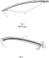
- Fig. 1 illustrates the light guide as an example of the current solution of the light guide fastening
- Fig. 2 illustrates the light guide fixed by a lengthwise fastening rib
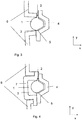
- Fig. 3 illustrates fastening of the light guide in the headlight in a cross-section
- Fig. 4 also illustrates fastening of the light guide in a cross-section, but the headlight is fitted with a cover filter.
- Fig. 2 The technical solution of the light guide 1 according to the invention is illustrated in Fig. 2 , where the light guide 1 is illustrated with the lengthwise fastening rib 2, which is located along more than one half of the length of the light guide 1 and is made of a clear transparent PC or PMMA material, just like the light guide 1.
- Fixing of the light guide 1 by the lengthwise fastening rib 2 in the motor vehicle headlight is illustrated in a cross-section in Fig. 3 .
- the lengthwise fastening rib 2 is gripped between the front cover 6 and the rear cover 4.
- the front cover 6 and the rear cover 4 are connected by any standard method (screw connections, pawls, etc.).
- This fixing of the lengthwise fastening rib 2 secures the delimitation of position of the light guide 1 in the x-axis.
- the bottom edge 3 of the light guide 1 fits closely to the internal surface of the rear cover 5, thus securing the delimitation of position of the light guide 1 in the y-axis.
- FIG. 4 Another example of the design is illustrated in a cross-section in Fig. 4 , where the headlight is fitted with a cover filter 7.
- the lengthwise fastening rib 2 is gripped between the cover filter 7 and the rear cover 4.
- the cover filter 7 is gripped between the front cover 6 and the rear cover 4, which are connected by any standard method (screw connections, pawls, etc.).
- This fixing of the lengthwise fastening rib 2 secures the delimitation of position of the light guide 1 in the x-axis.
- the bottom edge 3 of the light guide 1 fits to the internal surface of the rear cover 5, thus securing the delimitation of position of the light guide 1 in the y-axis.
Landscapes
- Physics & Mathematics (AREA)
- Engineering & Computer Science (AREA)
- General Engineering & Computer Science (AREA)
- General Physics & Mathematics (AREA)
- Optics & Photonics (AREA)
- Non-Portable Lighting Devices Or Systems Thereof (AREA)
- Planar Illumination Modules (AREA)
Description
- The invention comprises a motor vehicle headlight powered by LEDs comprising a light guide.
- For lighting of the motor vehicles are currently used light guides, which are powered by LEDs. This solution leads to a cost reduction because a small number of LEDs can be used in implementation of the signal functions. However, fastening of the light guide in the standard headlights presents a problem caused by a high demand for fit of the visual parts of the motor vehicle's exterior. Another problem is a demand for minimizing contact areas between the light guide and other components of the headlight, because the contact areas absorb the light that passes through the light guide, thus affecting the photometric output of the system and homogeneity of the emitted light.
- Various forms of lugs are presently used for fastening the light guide in the headlights. The lugs are distributed along the length of the headlight so that the light guide.can be fixed in the motor vehicle's headlight. The problem is that the light guide may not accurately fit with the other components, which are distant from the fastening points. Another problem is the fact that it is very difficult to conceal the lugs used for the fastening, which has a negative influence when assessing the homogeneity.
- Another state of the art can be seen in the document
US 2010/053987 A1 . It discloses the light guide in the motor vehicle headlight powered by LEDs, made of a clear transparent material and fitted with a fastening section in the form of a lengthwise fastening rib, which is located along more than one half of the length of the light guide. - This solution is lacking reliable and effective securing the delimitation of position of the light guide in the x-axis and y-axis.
- The drawbacks of the existing solutions are eliminated by invention, which comprise a motor vehicle headlight powered by LEDs comprising a light guide. The light guide is made of a clear transparent material such as PC or PMMA, fitted with a fastening section and powered by LEDs. PC is a polycarbonate and PMMA is a polymethyl acrylate i.e. a thermoplastic. The essence of the invention involves attachment of the light guide in standard headlights by a lengthwise fastening rib. This rib is located along more than one half of the length of the light guide and is also made of a clear transparent material such as PC or PMMA.
- The light guide is fixed by the lengthwise fastening rib. The lengthwise fastening rib is gripped between a front cover of a non-transparent glossy galvanized or non-galvanized material such as PC or ABS and a rear cover made of a non-transparent matt galvanized or non-galvanized material such as PC or ABS. ABS is acrylonitrile butadiene styrene, which is a thermoplastic. Gripping of the fastening rib between the front and rear cover delimits the position of the light guide in the x-axis. The bottom edge of the light guide fits closely to the internal surface of the rear cover, thus securing the delimitation of position of the light guide in the y-axis. The front and the rear covers are connected together by any standard method such as screw connections, pawls, etc.
- If the motor vehicle headlight is equipped with a cover filter of a clear or matt transparent material such as PC or PMMA and is gripped between the front and the rear cover, then the light guide is fixed by the lengthwise fastening rib between this cover filter and the rear cover. This secures the delimitation of position of the light guide in the x-axis. The bottom edge of the light guide fits closely to the internal surface of the rear cover, thus securing the delimitation of position of the light guide in the y-axis. The front and the rear covers are connected together by any standard method such as screw connections, pawls, etc.
- The invention is clearly explained by schematic drawings;
Fig. 1 illustrates the light guide as an example of the current solution of the light guide fastening,Fig. 2 illustrates the light guide fixed by a lengthwise fastening rib,Fig. 3 illustrates fastening of the light guide in the headlight in a cross-section andFig. 4 also illustrates fastening of the light guide in a cross-section, but the headlight is fitted with a cover filter. - The technical solution of the
light guide 1 according to the invention is illustrated inFig. 2 , where thelight guide 1 is illustrated with thelengthwise fastening rib 2, which is located along more than one half of the length of thelight guide 1 and is made of a clear transparent PC or PMMA material, just like thelight guide 1. - Fixing of the
light guide 1 by the lengthwise fasteningrib 2 in the motor vehicle headlight is illustrated in a cross-section inFig. 3 . Thelengthwise fastening rib 2 is gripped between thefront cover 6 and therear cover 4. Thefront cover 6 and therear cover 4 are connected by any standard method (screw connections, pawls, etc.). This fixing of thelengthwise fastening rib 2 secures the delimitation of position of thelight guide 1 in the x-axis. Thebottom edge 3 of thelight guide 1 fits closely to the internal surface of therear cover 5, thus securing the delimitation of position of thelight guide 1 in the y-axis. - Another example of the design is illustrated in a cross-section in
Fig. 4 , where the headlight is fitted with acover filter 7. Thelengthwise fastening rib 2 is gripped between thecover filter 7 and therear cover 4. Thecover filter 7 is gripped between thefront cover 6 and therear cover 4, which are connected by any standard method (screw connections, pawls, etc.). This fixing of thelengthwise fastening rib 2 secures the delimitation of position of thelight guide 1 in the x-axis. Thebottom edge 3 of thelight guide 1 fits to the internal surface of therear cover 5, thus securing the delimitation of position of thelight guide 1 in the y-axis. - Both mentioned examples of fastening ensure better fit of the components and also don't cause local non-homogeneity when the motor vehicle's headlights are on.
Claims (4)
- Motor vehicle headlight powered by LEDs comprising a light guide (1), which is made of a clear transparent material and fitted with a fastening section in the form of a lengthwise fastening rib (2), which is located along more than one half of the length of the light guide (1),
characterised in that
the light guide (1) is fixed by the lengthwise fastening rib (2) in the motor vehicle headlight, whereas for fixing the light guide (1) in the motor vehicle headlight the lengthwise fastening rib (2) is gripped in the motor vehicle headlight between a front cover (6) and a rear cover (4), thus securing the delimitation of position of the light guide (1) within the motor vehicle headlight in a first direction, whereas a bottom edge (3) of the light guide (1) is leaning against an inner surface of the rear cover (5), thus securing the delimitation of position of the light guide (1) within the motor vehicle headlight in a second direction, which extends perpendicular to the first direction, whereas the front cover (6) and the rear cover (4) are connected together by screw connections or pawls. - Motor vehicle headlight of claim 1, whereas the front cover (6) is in contact with a surface of the lengthwise fastening rib (2) and the rear cover (4) is in contact with another surface of the lengthwise fastening rib (2).
- Motor vehicle headlight powered by LEDs comprising a light guide (1), which is made of a clear transparent material and fitted with a fastening section in the form of a lengthwise fastening rib (2), which is located along more than one half of the length of the light guide (1),
characterised in that
the lengthwise fastening rib (2) that is gripped in the motor vehicle headlight between a cover filter (7) and a rear cover (4) and the cover filter (7) is gripped between a front cover (6) and the rear cover (4), thus securing the delimitation of position of the light guide (1) within the motor vehicle headlight in in a first direction, whereas a bottom edge (3) of the light guide (1) is leaning against an inner surface of the rear cover (5), thus securing the delimitation of position of the light guide (1) within the motor vehicle headlight in a second direction, which extends perpendicular to the first direction, whereas the front cover (6) and the rear cover (4) are connected together by screw connections or pawls. - Motor vehicle headlight of claim 3, whereas the cover filter (7) is in contact with a surface of the lengthwise fastening rib (2) and the rear cover (4) is in contact with another surface of the lengthwise fastening rib (2).
Applications Claiming Priority (2)
| Application Number | Priority Date | Filing Date | Title |
|---|---|---|---|
| CZ20120013A CZ201213A3 (en) | 2012-01-11 | 2012-01-11 | Optical waveguide |
| PCT/CZ2012/000113 WO2013104345A1 (en) | 2012-01-11 | 2012-11-06 | Light guide |
Publications (2)
| Publication Number | Publication Date |
|---|---|
| EP2802908A1 EP2802908A1 (en) | 2014-11-19 |
| EP2802908B1 true EP2802908B1 (en) | 2018-10-24 |
Family
ID=47429474
Family Applications (1)
| Application Number | Title | Priority Date | Filing Date |
|---|---|---|---|
| EP12805917.7A Active EP2802908B1 (en) | 2012-01-11 | 2012-11-06 | Motor vehicle headlight comprising a light guide |
Country Status (3)
| Country | Link |
|---|---|
| EP (1) | EP2802908B1 (en) |
| CZ (1) | CZ201213A3 (en) |
| WO (1) | WO2013104345A1 (en) |
Families Citing this family (4)
| Publication number | Priority date | Publication date | Assignee | Title |
|---|---|---|---|---|
| DE102013102258B4 (en) * | 2013-03-07 | 2023-02-02 | HELLA GmbH & Co. KGaA | Arrangement of an optical fiber in a lighting device of a vehicle |
| DE102015121324A1 (en) * | 2014-12-16 | 2016-06-16 | Automotive Lighting Reutlingen Gmbh | Lighting device for a motor vehicle |
| EP3081854B1 (en) * | 2015-04-13 | 2019-03-13 | SMR Patents S.à.r.l. | Light guide with reduced light attenuation |
| CN108375041A (en) * | 2016-10-27 | 2018-08-07 | 标致·雪铁龙汽车公司 | Light guide fixation kit, car light and vehicle for car light |
Family Cites Families (9)
| Publication number | Priority date | Publication date | Assignee | Title |
|---|---|---|---|---|
| DE1995520U (en) * | 1968-08-23 | 1968-10-31 | Daimler Benz Ag | LIGHT, IN PARTICULAR EXTERIOR LIGHT FOR MOTOR VEHICLES. |
| DE29702746U1 (en) * | 1997-02-18 | 1997-04-03 | Reitter & Schefenacker GmbH & Co. KG, 73730 Esslingen | Exterior rear view mirror for vehicles, preferably for motor vehicles |
| JP3225005B2 (en) * | 1997-06-17 | 2001-11-05 | 株式会社小糸製作所 | Vehicle lighting |
| DE10209588A1 (en) * | 2002-03-05 | 2003-10-23 | Volkswagen Ag | Headlight arrangement for vehicles with a main light source and a direction indicator |
| US6915062B2 (en) * | 2002-03-06 | 2005-07-05 | Federal-Mogul World Wide, Inc. | Illuminating waveguide |
| JP5091808B2 (en) * | 2008-09-02 | 2012-12-05 | 株式会社小糸製作所 | Vehicle lighting |
| FR2936296B1 (en) * | 2008-09-25 | 2011-09-02 | Valeo Vision Sas | LIGHTING DEVICE COMPRISING A GUIDE TABLE |
| DE202009010837U1 (en) * | 2009-08-13 | 2009-11-12 | Johnson Controls Technology Company, Holland | Optical fiber with non-uniform cross-section and mounting flange |
| FR2967235B1 (en) * | 2010-11-05 | 2014-10-31 | Valeo Vision | LIGHTING OR SIGNALING DEVICE FOR A MOTOR VEHICLE HAVING A LIGHT GUIDE RAIL. |
-
2012
- 2012-01-11 CZ CZ20120013A patent/CZ201213A3/en unknown
- 2012-11-06 WO PCT/CZ2012/000113 patent/WO2013104345A1/en active Application Filing
- 2012-11-06 EP EP12805917.7A patent/EP2802908B1/en active Active
Non-Patent Citations (1)
| Title |
|---|
| None * |
Also Published As
| Publication number | Publication date |
|---|---|
| CZ201213A3 (en) | 2013-07-24 |
| WO2013104345A1 (en) | 2013-07-18 |
| EP2802908A1 (en) | 2014-11-19 |
Similar Documents
| Publication | Publication Date | Title |
|---|---|---|
| EP2802908B1 (en) | Motor vehicle headlight comprising a light guide | |
| EP2990720B1 (en) | Vehicle lighting unit | |
| CN204037480U (en) | Vehicle interior part | |
| US9016918B2 (en) | Lighting device | |
| CN101486367B (en) | Straddle type vehicle | |
| FR2947325B1 (en) | OPTICAL DEVICE, IN PARTICULAR FOR MOTOR VEHICLE | |
| CN103153702A (en) | Signalling lamps for motor vehicle | |
| US8408768B2 (en) | Lighting device for a vehicle | |
| CN107431785A (en) | A kind of low gloss housing unit for driver assistance system image pick-up device | |
| CN102734726A (en) | Lighting device with closed form for a motor vehicle | |
| US20140340921A1 (en) | Mirror device for motor vehicles | |
| CN204420816U (en) | Integrate the Vehicular lamp turning to instruction and lane change warning | |
| CN115697764A (en) | Vehicle lighting unit | |
| WO2017052478A1 (en) | Position light structure for motorcycle | |
| US10436416B2 (en) | Vehicle light assembly with heat sink | |
| JP2006232008A (en) | Vehicle recognition device | |
| EP2853444B1 (en) | Mirror device for motor vehicles and method for assembling thereof | |
| US8167343B2 (en) | Device for attachment of a bumper covering | |
| US20160097506A1 (en) | Lighting and/or signaling device with side signaling function | |
| EP2610108A1 (en) | A system, method, and apparatus for integral backlight for an automotive | |
| CN109140379A (en) | Component including procapsid, back casing and the electronic circuit board for being fixed between the procapsid and the back casing | |
| CN107018657B (en) | Customizable modular lamp | |
| CN208746100U (en) | Truck mud flap component | |
| CN205589363U (en) | Electric bicycle's headlight scintillation structure | |
| CN110131669A (en) | The illumination of motor vehicles and/or luminous intensity signal |
Legal Events
| Date | Code | Title | Description |
|---|---|---|---|
| PUAI | Public reference made under article 153(3) epc to a published international application that has entered the european phase |
Free format text: ORIGINAL CODE: 0009012 |
|
| 17P | Request for examination filed |
Effective date: 20140811 |
|
| AK | Designated contracting states |
Kind code of ref document: A1 Designated state(s): AL AT BE BG CH CY CZ DE DK EE ES FI FR GB GR HR HU IE IS IT LI LT LU LV MC MK MT NL NO PL PT RO RS SE SI SK SM TR |
|
| DAX | Request for extension of the european patent (deleted) | ||
| 17Q | First examination report despatched |
Effective date: 20170413 |
|
| GRAP | Despatch of communication of intention to grant a patent |
Free format text: ORIGINAL CODE: EPIDOSNIGR1 |
|
| RIC1 | Information provided on ipc code assigned before grant |
Ipc: G02B 6/00 20060101AFI20180622BHEP Ipc: F21V 8/00 20060101ALI20180622BHEP Ipc: F21S 41/24 20180101ALI20180622BHEP Ipc: F21S 41/29 20180101ALI20180622BHEP |
|
| INTG | Intention to grant announced |
Effective date: 20180725 |
|
| RIN1 | Information on inventor provided before grant (corrected) |
Inventor name: TRUHLAR JAN |
|
| GRAS | Grant fee paid |
Free format text: ORIGINAL CODE: EPIDOSNIGR3 |
|
| GRAA | (expected) grant |
Free format text: ORIGINAL CODE: 0009210 |
|
| AK | Designated contracting states |
Kind code of ref document: B1 Designated state(s): AL AT BE BG CH CY CZ DE DK EE ES FI FR GB GR HR HU IE IS IT LI LT LU LV MC MK MT NL NO PL PT RO RS SE SI SK SM TR |
|
| REG | Reference to a national code |
Ref country code: CH Ref legal event code: EP |
|
| REG | Reference to a national code |
Ref country code: IE Ref legal event code: FG4D |
|
| REG | Reference to a national code |
Ref country code: AT Ref legal event code: REF Ref document number: 1057344 Country of ref document: AT Kind code of ref document: T Effective date: 20181115 |
|
| REG | Reference to a national code |
Ref country code: DE Ref legal event code: R096 Ref document number: 602012052651 Country of ref document: DE |
|
| REG | Reference to a national code |
Ref country code: NL Ref legal event code: MP Effective date: 20181024 |
|
| REG | Reference to a national code |
Ref country code: LT Ref legal event code: MG4D |
|
| REG | Reference to a national code |
Ref country code: AT Ref legal event code: MK05 Ref document number: 1057344 Country of ref document: AT Kind code of ref document: T Effective date: 20181024 |
|
| PG25 | Lapsed in a contracting state [announced via postgrant information from national office to epo] |
Ref country code: NL Free format text: LAPSE BECAUSE OF FAILURE TO SUBMIT A TRANSLATION OF THE DESCRIPTION OR TO PAY THE FEE WITHIN THE PRESCRIBED TIME-LIMIT Effective date: 20181024 |
|
| PG25 | Lapsed in a contracting state [announced via postgrant information from national office to epo] |
Ref country code: IS Free format text: LAPSE BECAUSE OF FAILURE TO SUBMIT A TRANSLATION OF THE DESCRIPTION OR TO PAY THE FEE WITHIN THE PRESCRIBED TIME-LIMIT Effective date: 20190224 Ref country code: FI Free format text: LAPSE BECAUSE OF FAILURE TO SUBMIT A TRANSLATION OF THE DESCRIPTION OR TO PAY THE FEE WITHIN THE PRESCRIBED TIME-LIMIT Effective date: 20181024 Ref country code: HR Free format text: LAPSE BECAUSE OF FAILURE TO SUBMIT A TRANSLATION OF THE DESCRIPTION OR TO PAY THE FEE WITHIN THE PRESCRIBED TIME-LIMIT Effective date: 20181024 Ref country code: LT Free format text: LAPSE BECAUSE OF FAILURE TO SUBMIT A TRANSLATION OF THE DESCRIPTION OR TO PAY THE FEE WITHIN THE PRESCRIBED TIME-LIMIT Effective date: 20181024 Ref country code: AT Free format text: LAPSE BECAUSE OF FAILURE TO SUBMIT A TRANSLATION OF THE DESCRIPTION OR TO PAY THE FEE WITHIN THE PRESCRIBED TIME-LIMIT Effective date: 20181024 Ref country code: LV Free format text: LAPSE BECAUSE OF FAILURE TO SUBMIT A TRANSLATION OF THE DESCRIPTION OR TO PAY THE FEE WITHIN THE PRESCRIBED TIME-LIMIT Effective date: 20181024 Ref country code: NO Free format text: LAPSE BECAUSE OF FAILURE TO SUBMIT A TRANSLATION OF THE DESCRIPTION OR TO PAY THE FEE WITHIN THE PRESCRIBED TIME-LIMIT Effective date: 20190124 Ref country code: ES Free format text: LAPSE BECAUSE OF FAILURE TO SUBMIT A TRANSLATION OF THE DESCRIPTION OR TO PAY THE FEE WITHIN THE PRESCRIBED TIME-LIMIT Effective date: 20181024 Ref country code: PL Free format text: LAPSE BECAUSE OF FAILURE TO SUBMIT A TRANSLATION OF THE DESCRIPTION OR TO PAY THE FEE WITHIN THE PRESCRIBED TIME-LIMIT Effective date: 20181024 Ref country code: BG Free format text: LAPSE BECAUSE OF FAILURE TO SUBMIT A TRANSLATION OF THE DESCRIPTION OR TO PAY THE FEE WITHIN THE PRESCRIBED TIME-LIMIT Effective date: 20190124 |
|
| PG25 | Lapsed in a contracting state [announced via postgrant information from national office to epo] |
Ref country code: PT Free format text: LAPSE BECAUSE OF FAILURE TO SUBMIT A TRANSLATION OF THE DESCRIPTION OR TO PAY THE FEE WITHIN THE PRESCRIBED TIME-LIMIT Effective date: 20190224 Ref country code: AL Free format text: LAPSE BECAUSE OF FAILURE TO SUBMIT A TRANSLATION OF THE DESCRIPTION OR TO PAY THE FEE WITHIN THE PRESCRIBED TIME-LIMIT Effective date: 20181024 Ref country code: SE Free format text: LAPSE BECAUSE OF FAILURE TO SUBMIT A TRANSLATION OF THE DESCRIPTION OR TO PAY THE FEE WITHIN THE PRESCRIBED TIME-LIMIT Effective date: 20181024 Ref country code: GR Free format text: LAPSE BECAUSE OF FAILURE TO SUBMIT A TRANSLATION OF THE DESCRIPTION OR TO PAY THE FEE WITHIN THE PRESCRIBED TIME-LIMIT Effective date: 20190125 Ref country code: RS Free format text: LAPSE BECAUSE OF FAILURE TO SUBMIT A TRANSLATION OF THE DESCRIPTION OR TO PAY THE FEE WITHIN THE PRESCRIBED TIME-LIMIT Effective date: 20181024 |
|
| REG | Reference to a national code |
Ref country code: CH Ref legal event code: PL |
|
| REG | Reference to a national code |
Ref country code: DE Ref legal event code: R097 Ref document number: 602012052651 Country of ref document: DE |
|
| PG25 | Lapsed in a contracting state [announced via postgrant information from national office to epo] |
Ref country code: LU Free format text: LAPSE BECAUSE OF NON-PAYMENT OF DUE FEES Effective date: 20181106 Ref country code: IT Free format text: LAPSE BECAUSE OF FAILURE TO SUBMIT A TRANSLATION OF THE DESCRIPTION OR TO PAY THE FEE WITHIN THE PRESCRIBED TIME-LIMIT Effective date: 20181024 Ref country code: DK Free format text: LAPSE BECAUSE OF FAILURE TO SUBMIT A TRANSLATION OF THE DESCRIPTION OR TO PAY THE FEE WITHIN THE PRESCRIBED TIME-LIMIT Effective date: 20181024 |
|
| REG | Reference to a national code |
Ref country code: BE Ref legal event code: MM Effective date: 20181130 |
|
| REG | Reference to a national code |
Ref country code: IE Ref legal event code: MM4A |
|
| PG25 | Lapsed in a contracting state [announced via postgrant information from national office to epo] |
Ref country code: EE Free format text: LAPSE BECAUSE OF FAILURE TO SUBMIT A TRANSLATION OF THE DESCRIPTION OR TO PAY THE FEE WITHIN THE PRESCRIBED TIME-LIMIT Effective date: 20181024 Ref country code: LI Free format text: LAPSE BECAUSE OF NON-PAYMENT OF DUE FEES Effective date: 20181130 Ref country code: CH Free format text: LAPSE BECAUSE OF NON-PAYMENT OF DUE FEES Effective date: 20181130 Ref country code: SM Free format text: LAPSE BECAUSE OF FAILURE TO SUBMIT A TRANSLATION OF THE DESCRIPTION OR TO PAY THE FEE WITHIN THE PRESCRIBED TIME-LIMIT Effective date: 20181024 Ref country code: MC Free format text: LAPSE BECAUSE OF FAILURE TO SUBMIT A TRANSLATION OF THE DESCRIPTION OR TO PAY THE FEE WITHIN THE PRESCRIBED TIME-LIMIT Effective date: 20181024 Ref country code: RO Free format text: LAPSE BECAUSE OF FAILURE TO SUBMIT A TRANSLATION OF THE DESCRIPTION OR TO PAY THE FEE WITHIN THE PRESCRIBED TIME-LIMIT Effective date: 20181024 Ref country code: SK Free format text: LAPSE BECAUSE OF FAILURE TO SUBMIT A TRANSLATION OF THE DESCRIPTION OR TO PAY THE FEE WITHIN THE PRESCRIBED TIME-LIMIT Effective date: 20181024 |
|
| PLBE | No opposition filed within time limit |
Free format text: ORIGINAL CODE: 0009261 |
|
| STAA | Information on the status of an ep patent application or granted ep patent |
Free format text: STATUS: NO OPPOSITION FILED WITHIN TIME LIMIT |
|
| GBPC | Gb: european patent ceased through non-payment of renewal fee |
Effective date: 20190124 |
|
| 26N | No opposition filed |
Effective date: 20190725 |
|
| PG25 | Lapsed in a contracting state [announced via postgrant information from national office to epo] |
Ref country code: IE Free format text: LAPSE BECAUSE OF NON-PAYMENT OF DUE FEES Effective date: 20181106 Ref country code: FR Free format text: LAPSE BECAUSE OF NON-PAYMENT OF DUE FEES Effective date: 20181224 Ref country code: SI Free format text: LAPSE BECAUSE OF FAILURE TO SUBMIT A TRANSLATION OF THE DESCRIPTION OR TO PAY THE FEE WITHIN THE PRESCRIBED TIME-LIMIT Effective date: 20181024 |
|
| PG25 | Lapsed in a contracting state [announced via postgrant information from national office to epo] |
Ref country code: BE Free format text: LAPSE BECAUSE OF NON-PAYMENT OF DUE FEES Effective date: 20181130 |
|
| PG25 | Lapsed in a contracting state [announced via postgrant information from national office to epo] |
Ref country code: GB Free format text: LAPSE BECAUSE OF NON-PAYMENT OF DUE FEES Effective date: 20190124 |
|
| PG25 | Lapsed in a contracting state [announced via postgrant information from national office to epo] |
Ref country code: MT Free format text: LAPSE BECAUSE OF NON-PAYMENT OF DUE FEES Effective date: 20181106 |
|
| PG25 | Lapsed in a contracting state [announced via postgrant information from national office to epo] |
Ref country code: TR Free format text: LAPSE BECAUSE OF FAILURE TO SUBMIT A TRANSLATION OF THE DESCRIPTION OR TO PAY THE FEE WITHIN THE PRESCRIBED TIME-LIMIT Effective date: 20181024 |
|
| PG25 | Lapsed in a contracting state [announced via postgrant information from national office to epo] |
Ref country code: HU Free format text: LAPSE BECAUSE OF FAILURE TO SUBMIT A TRANSLATION OF THE DESCRIPTION OR TO PAY THE FEE WITHIN THE PRESCRIBED TIME-LIMIT; INVALID AB INITIO Effective date: 20121106 Ref country code: MK Free format text: LAPSE BECAUSE OF NON-PAYMENT OF DUE FEES Effective date: 20181024 Ref country code: CY Free format text: LAPSE BECAUSE OF FAILURE TO SUBMIT A TRANSLATION OF THE DESCRIPTION OR TO PAY THE FEE WITHIN THE PRESCRIBED TIME-LIMIT Effective date: 20181024 |
|
| PGFP | Annual fee paid to national office [announced via postgrant information from national office to epo] |
Ref country code: CZ Payment date: 20230306 Year of fee payment: 12 |
|
| P01 | Opt-out of the competence of the unified patent court (upc) registered |
Effective date: 20230626 |
|
| PGFP | Annual fee paid to national office [announced via postgrant information from national office to epo] |
Ref country code: DE Payment date: 20230731 Year of fee payment: 12 |