EP2802899B1 - Parameterizing a geological subsurface feature - Google Patents
Parameterizing a geological subsurface feature Download PDFInfo
- Publication number
- EP2802899B1 EP2802899B1 EP13736094.7A EP13736094A EP2802899B1 EP 2802899 B1 EP2802899 B1 EP 2802899B1 EP 13736094 A EP13736094 A EP 13736094A EP 2802899 B1 EP2802899 B1 EP 2802899B1
- Authority
- EP
- European Patent Office
- Prior art keywords
- level set
- subsurface
- function
- geometry
- gradient
- Prior art date
- Legal status (The legal status is an assumption and is not a legal conclusion. Google has not performed a legal analysis and makes no representation as to the accuracy of the status listed.)
- Not-in-force
Links
Images


Classifications
-
- G—PHYSICS
- G01—MEASURING; TESTING
- G01V—GEOPHYSICS; GRAVITATIONAL MEASUREMENTS; DETECTING MASSES OR OBJECTS; TAGS
- G01V1/00—Seismology; Seismic or acoustic prospecting or detecting
- G01V1/28—Processing seismic data, e.g. analysis, for interpretation, for correction
-
- G—PHYSICS
- G01—MEASURING; TESTING
- G01V—GEOPHYSICS; GRAVITATIONAL MEASUREMENTS; DETECTING MASSES OR OBJECTS; TAGS
- G01V2210/00—Details of seismic processing or analysis
- G01V2210/60—Analysis
- G01V2210/67—Wave propagation modeling
Landscapes
- Engineering & Computer Science (AREA)
- Remote Sensing (AREA)
- Physics & Mathematics (AREA)
- Life Sciences & Earth Sciences (AREA)
- Acoustics & Sound (AREA)
- Environmental & Geological Engineering (AREA)
- Geology (AREA)
- General Life Sciences & Earth Sciences (AREA)
- General Physics & Mathematics (AREA)
- Geophysics (AREA)
- Geophysics And Detection Of Objects (AREA)
Description
- This application claims the benefit of
U.S. Provisional Patent App. Serial No. 61/586,659 filed January 13, 2012 U.S. Non-provisional Patent App. Serial No. 13/619,508 filed September 14, 2012 - Full-waveform inversion (FWI) is a method that may be used to build, for example, a high resolution seismic velocity model from the nonlinear, iterative minimization of the misfit between observed and synthetic data. The task of accurately recovering the geometry of salt bodies, typically found in geologically complex marine environments like the Gulf of Mexico, presents a great challenge to FWI for many reasons, one of which being the lack of low frequencies in the data. Therefore, the salt geometry often must be manually picked by seismic interpreters, which is not only subjective but is also a time-consuming and costly process. It also has proved difficult to invert density using traditional FWI when using, for example, the Gardner approximation at a subsurface boundary. Better definition of the salt geometry has been shown to improve imaging in the subsalt sedimentary regions.
- A Aghasi et al, in "Parametric Level Set Methods for Inverse Problems", Arxiv.org, Cornell University Library, 7 October 2011, provides a general overview of level set methods. J.H. Sanders et al, in "Constrained resistivity inversion using seismic data", Geophysics Journal International, proposes a method of constraining structure in anisotropic electrical resistivity inversion. D. Vigh et al, in "3D Full waveform inversion of a Gulf of Mexico WAZ data set", SEG Expanded Abstracts, pp957-961, January 2010 describes use of full waveform inversion applied to wide-azimuth (WAZ) data set.
US 2011/115787 proposes a unified approach in the form of an Interactive "Violation" (simultaneous visualization and simulation) Environment (IVE) designed to efficiently segment geologic features with high accuracy. The IVE unifies image structure analysis and implicit surface modeling as a surface-driven solution that assists analysts, such as geoscientists, in the segmentation and modeling of faults, channels, and other geobodies in 3-D data, such as 3-D seismic data. - In accordance with the invention a method is performed that includes: receiving, by a system including a processor, acquired data corresponding to a subsurface, geological formation, wherein the acquired data includes data corresponding to a subsurface body having a certain geometry and a subsurface region; and directly inverting, by the system, into an inversion domain at least part of the subsurface body geometry, wherein the direct inverting includes partitioning the inversion domain into a first partitioned region, corresponding at least in part to the subsurface body, and a second partitioned region, using a level set representation to parameterize the subsurface body geometry defining an implicit model using a level set function; generating an objective function; determining a gradient of the objective function; at an iteration, perturbing the level set boundary by evolving the level set function; and stopping the evolution of the level set function when the step length (time step) along the time dimension meets one or more predetermined conditions.
- A computing system includes at least one processor, at least one memory, and one or more programs stored in the at least one memory, wherein the one or more programs are configured to be executed by the one or more processors, the one or more programs including instructions for: acquiring data corresponding to a subsurface, geological formation, wherein the acquired data includes data corresponding to a subsurface body having a certain geometry and a subsurface region; and directly inverting into an inversion domain at least part of the subsurface body geometry, wherein the direct inverting includes partitioning the inversion domain into a first partitioned region, corresponding at least in part to the subsurface body, and a second partitioned region, and using a level set representation to parameterize the subsurface body geometry.
- A computer readable storage medium may be provided, the medium having a set of one or more programs including instructions that when executed by a computing system cause the computing system to: acquire data corresponding to a subsurface, geological formation, wherein the acquired data includes data corresponding to a subsurface body having a certain geometry and a subsurface region; and directly invert into an inversion domain at least part of the subsurface body geometry, wherein the direct inverting includes partitioning the inversion domain into a first partitioned region, corresponding at least in part to the subsurface body, and a second partitioned region, and using a level set representation to parameterize the subsurface body geometry.
- In accordance with some embodiments, a computing system is provided that includes at least one processor, at least one memory, and one or more programs stored in the at least one memory; wherein the programs comprise instructions, which when executed by the at least one processor, are configured to perform a method of the invention.
- An information processing apparatus for use in a computing system may further be provided, and includes means for acquiring data corresponding to a subsurface, geological formation, wherein the acquired data includes data corresponding to a subsurface body having a certain geometry and a subsurface region; and means for directly inverting into an inversion domain at least part of the subsurface body geometry, wherein the direct inverting includes partitioning the inversion domain into a first partitioned region, corresponding at least in part to the subsurface body, and a second partitioned region, and using a level set representation to parameterize the subsurface body geometry.
- Another method includes: acquiring data corresponding to a subsurface, geological formation, wherein the acquired data includes data corresponding to a subsurface body having a certain geometry and a subsurface region; and performing a full waveform inversion using a level set representation to parameterize the subsurface body geometry.
- Another computing system includes at least one processor, at least one memory, and one or more programs stored in the at least one memory, wherein the one or more programs are configured to be executed by the one or more processors, the one or more programs including instructions for: acquiring data corresponding to a subsurface, geological formation, wherein the acquired data includes data corresponding to a subsurface body having a certain geometry and a subsurface region; and performing a full waveform inversion using a level set representation to parameterize the subsurface body geometry.
- Another computer readable storage medium has a set of one or more programs including instructions that when executed by a computing system cause the computing system to: acquire data corresponding to a subsurface, geological formation, wherein the acquired data includes data corresponding to a subsurface body having a certain geometry and a subsurface region; and perform a full waveform inversion using a level set representation to parameterize the subsurface body geometry.
- Another computing system includes at least one processor, at least one memory, and one or more programs stored in the at least one memory; and means for acquiring data corresponding to a subsurface, geological formation, wherein the acquired data includes data corresponding to a subsurface body having a certain geometry and a subsurface region; and means for performing a full waveform inversion using a level set representation to parameterize the subsurface body geometry.
- Another information processing apparatus for use in a computing system includes means for acquiring data corresponding to a subsurface, geological formation, wherein the acquired data includes data corresponding to a subsurface body having a certain geometry and a subsurface region; and means for performing a full waveform inversion using a level set representation to parameterize the subsurface body geometry.
- Another method includes: acquiring data corresponding to a subsurface, geological formation, wherein the acquired data includes data corresponding to a subsurface body having a certain geometry and a subsurface region; and using a level set representation to parameterize the subsurface body geometry.
- Another computing system includes at least one processor, at least one memory, and one or more programs stored in the at least one memory, wherein the one or more programs are configured to be executed by the one or more processors, the one or more programs including instructions for acquiring data corresponding to a subsurface, geological formation, wherein the acquired data includes data corresponding to a subsurface body having a certain geometry and a subsurface region; and using a level set representation to parameterize the subsurface body geometry.
- Another computer readable storage medium has a set of one or more programs including instructions that when executed by a computing system cause the computing system to: acquire data corresponding to a subsurface, geological formation, wherein the acquired data includes data corresponding to a subsurface body having a certain geometry and a subsurface region; and use a level set representation to parameterize the subsurface body geometry.
- Another computing system includes at least one processor, at least one memory, and one or more programs stored in the at least one memory; and means for acquiring data corresponding to a subsurface, geological formation, wherein the acquired data includes data corresponding to a subsurface body having a certain geometry and a subsurface region; and means for using a level set representation to parameterize the subsurface body geometry.
- Another information processing apparatus for use in a computing system includes means for acquiring data corresponding to a subsurface, geological formation, wherein the acquired data includes data corresponding to a subsurface body having a certain geometry and a subsurface region; and means for using a level set representation to parameterize the subsurface body geometry.
- In some embodiments, an aspect of the invention includes that the subsurface body comprises a salt body and the subsurface region comprises a sediment region, and the first partitioned region corresponds at least in part to the salt body and the second partitioned region corresponds at least in part to the sediment region.
- In some embodiments, an aspect of the invention includes that the direct inverting further comprises mapping the implicit model onto a grid.
- In some embodiments, an aspect of the invention includes that a direction for the determined time step is determined using a technique selected from the group consisting of a steepest descent direction, a conjugate gradient direction, a Newton direction, and a quasi-Newton direction.
- In some embodiments, the direction for the determined time step is determined using a steepest descent technique and an aspect of the invention includes that the direct inverting further comprises using a negative of the gradient as a force acting on the level set boundary to evolve the level set function.
- In some embodiments, an aspect of the invention includes that a zero level set of the level set function represents the boundary of the domain being inverted.
- In some embodiments, the gradient is defined only on the level set boundary and an aspect of the invention involves providing a continuous extension of the gradient off of the level set boundary.
- In some embodiments, the gradient is defined only on the level set boundary and a level set evolution equation is used to evolve the level set function, and an aspect of the invention includes that the direct inverting further comprises, choosing the level set function to be a signed distance function; constructing the signed distance function; and computing a constant extrapolation of the gradient along a direction normal to the boundary.
- In some embodiments, an aspect of the invention includes that the evolving the level set function comprises using an equation of motion.
- In some embodiments, an aspect of the invention includes that the objective function is a least-squares formulation.
- In some embodiments, an aspect of the invention includes that the direct inversion further comprises determining the misfit between the acquired data and synthetic data.
- In some embodiments, an aspect of the invention includes that the level set representation is positive if representing the first partitioned region and negative if representing the second partitioned region.
- In some embodiments, an aspect of the invention includes that the direct inversion comprises a full waveform inversion.
- In some embodiments, an aspect of the invention involves determining the geometry of the subsurface body.
- In some embodiments, an aspect of the invention involves plotting velocity profiles of the subsurface body.
- This summary is provided to introduce a selection of concepts that are further described below in the detailed description. This summary is not intended to identify key or essential features of the claimed subject matter, nor is it intended to be used as an aid in limiting the scope of the claimed subject matter.
- Embodiments of processing acquired data for geophysical interpretation are described with reference to the following figures. The same numbers are generally used throughout the figures to reference like features and components.
-
Figure 1 shows a flowchart in which acquired data is processed for geophysical interpretation, in accordance with the present disclosure. -
Figure 2 schematically shows a level set function and its domain, in accordance with the present disclosure. -
Figure 3 shows a flowchart of an inversion workflow, in accordance with the present disclosure. -
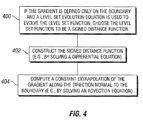
Figure 4 shows a flowchart of an extrapolation workflow, in accordance with the present disclosure. -
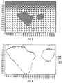
Figure 5 shows a model having a linearly increasing velocity in the sediment region and two salt bodies, in accordance with the present disclosure. -
Figure 6 is an example graph showing the difference between the true velocity and the starting velocity, in accordance with the present disclosure. -
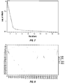
Figure 7 is an example graph showing a log of data misfit versus iterations, in accordance with the present disclosure. -
Figure 8 is an example graph showing the difference between the true velocity and the inverted velocity, in accordance with the present disclosure. -
Figure 9 is an example graph of the velocity depth profiles showing true velocity, starting velocity, and inverted velocity at x = 2100 (52,500 ft.), in accordance with the present disclosure. -
Figure 10 is an example graph of the velocity depth profiles showing true velocity, starting velocity, and inverted velocity at x = 3500 (87,500 ft.), in accordance with the present disclosure. -
Figure 11 is an example graph showing the objective function behavior as the salt geometry is shrunk (negative axis) and expanded (positive axis), in accordance with the present disclosure. -
Figure 12 is an example graph showing the steepest descent force on the level set function when the salt geometry is expanded (X component), in accordance with the present disclosure. -
Figure 13 is an example graph showing the steepest descent force on the level set function when the salt geometry is expanded (Z component), in accordance with the present disclosure. -
Figure 14 is an example graph showing the steepest descent force on the level set function when the salt geometry is shrunk (X component), in accordance with the present disclosure. -
Figure 15 is an example graph showing the steepest descent force on the level set function when the salt geometry is shrunk (Z component), in accordance with the present disclosure. -
Figure 16 is an example plot of an alternative embodiment velocity model, in accordance with the present disclosure. -
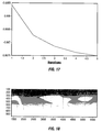
Figure 17 is an example plot of the data misfit versus iterations for the inversion on the alternative embodiment (ofFigure 16 ) dataset, in accordance with the present disclosure. -
Figure 18 shows the location of the velocity profiles for the inversion on the alternative embodiment (ofFigure 16 ) dataset, in accordance with the present disclosure. -
Figure 19 is an example plot showing the velocity depth profiles with true velocity, starting velocity, and inverted velocity at x = 2000 in the alternative embodiment (ofFigure 16 ) dataset, in accordance with the present disclosure. -
Figure 20 is an example plot showing the velocity depth profiles with true velocity, starting velocity, and inverted velocity at x = 3000 in the alternative embodiment (ofFigure 16 ) dataset, in accordance with the present disclosure. -
Figure 21 is an example plot showing the velocity depth profiles with true velocity, starting velocity, and inverted velocity at x = 4000 in the alternative embodiment (ofFigure 16 ) dataset, in accordance with the present disclosure. -
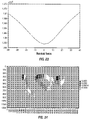
Figure 22 is an example plot showing the velocity depth profiles with true velocity, starting velocity, and inverted velocity at x = 5100 in the alternative embodiment (ofFigure 16 ) dataset, in accordance with the present disclosure. -
Figure 23 is an example graph showing the objective function behavior when the salt body in the alternative embodiment (ofFigure 16 ) dataset is shrunk (negative axis) and expanded (positive axis), in accordance with the present disclosure. -
Figure 24 is an example graph showing the steepest descent force acting on the salt boundary when the salt body is expanded in the alternative embodiment (ofFigure 16 ) dataset (X component), in accordance with the present disclosure. -
Figure 25 is an example graph showing the steepest descent force acting on the salt boundary when the salt body is expanded in the alternative embodiment (ofFigure 16 ) dataset (Z component), in accordance with the present disclosure. -
Figure 26 illustrates a computing system, in accordance with the present disclosure. - It should be understood that the drawings are not to scale and that the disclosed embodiments are sometimes illustrated diagrammatically and in partial views. In certain instances, details that are not necessary for an understanding of the disclosed method and apparatus or that would render other details difficult to perceive may have been omitted. It should be understood that this disclosure is not limited to the particular embodiments illustrated herein.
- Some embodiments will now be described with reference to the figures. Like elements in the various figures may be referenced with like numbers for consistency. In the following description, numerous details are set forth to provide an understanding of various embodiments and/or features. However, it will be understood by those skilled in the art that some embodiments may be practiced without many of these details and that numerous variations or modifications from the described embodiments are possible. As used here, the terms "above" and "below," "up" and "down," "upper" and "lower," "upwardly" and "downwardly," and other like terms indicating relative positions above or below a given point or element are used in this description to more clearly describe certain embodiments. However, when applied to equipment and methods for use in wells that are deviated or horizontal, such terms may refer to a left to right, right to left or diagonal relationship, as appropriate.
- It will also be understood that, although the terms first, second, etc. may be used herein to describe various elements, these elements should not be limited by these terms. These terms are only used to distinguish one element from another. For example, a first object or step could be termed a second object or step, and, similarly, a second object or step could be termed a first object or step, without departing from the scope of the invention. The first object or step, and the second object or step, are both objects or steps, respectively, but they are not to be considered the same object or step.
- The terminology used in the description of the invention herein is for the purpose of describing particular embodiments only and is not intended to be limiting of the invention. As used in the description of the invention and the appended claims, the singular forms "a," "an" and "the" are intended to include the plural forms as well, unless the context clearly indicates otherwise. It will also be understood that the term "and/or" as used herein refers to and encompasses any and all possible combinations of one or more of the associated listed items. It will be further understood that the terms "includes," "including," "comprises," and/or "comprising," when used in this specification, specify the presence of stated features, integers, steps, operations, elements and/or components, but do not preclude the presence or addition of one or more other features, integers, steps, operations, elements, components and/or groups thereof.
- As used herein, the term "if" may be construed to mean "when" or "upon" or "in response to determining" or "in response to detecting," depending on the context. Similarly, the phrase "if it is determined" or "if [a stated condition or event] is detected" may be construed to mean "upon determining" or "in response to determining" or "upon detecting [the stated condition or event]" or "in response to detecting [the stated condition or event]," depending on the context.
- A system and method to parameterize the geometry of a subsurface feature (e.g., salt body) are disclosed. While this disclosure involves the procedure to accomplish full waveform inversion (FWI) using a level set approach to parameterize salt geometry and recover salt geometry from observed seismic data, those of ordinary skill in the art will recognize that the various disclosed embodiments may be applied in many contexts for many types of collected data to image features in a subsurface region.
- In one embodiment, one may directly invert the geometry of subsurface features using FWI. Salt bodies, for example, are subsurface features for which the method disclosed herein may be used. Providing better definition of the salt geometry (e.g., boundary) improves the imaging in the subsalt sedimentary regions. The FWI technique may include partitioning the inversion domain into first (e.g., salt) and second (e.g., sediment) regions, and using a level set representation to parameterize the first body (salt) geometry. This is illustrated in a flowchart format in
Figure 1 , which shows that data corresponding to a subsurface, geological formation is acquired, wherein the acquired data includes data corresponding to a subsurface body having a certain geometry and a subsurface region (200). At least part of the subsurface body geometry is directly inverted into an inversion domain, wherein the direct inversion includes: (1) partitioning the inversion domain into a first partitioned region corresponding at least in part to the subsurface body, and a second partitioned region; and (2) using a level set representation to parameterize the subsurface body geometry (202). - The classical least-squares formulation of the full waveform inversion problem can be described as follows. F is the function or forward modeling operator


- At each (or one or more) iteration k, the model is updated according to the rule x k+1=xk +αkpk, where αk is the step length determined by a line search procedure, and the direction, pk , could be, for example, depending on the optimization technique being used, one of steepest descent, conjugate gradient, or Newton/quasi-Newton direction.
- For any real-valued function ƒ that mapsinto


 into
into
 such that its zero level set, Γ(0), is the boundary, ∂Ω, of the domain, Ω, that we wish to represent and invert, as schematically illustrated in
Figure 2 . - The level set function ƒ is made positive in Ω (e.g., the salt) and negative in Ωc (e.g., the sediment). The level set approach may be adapted to solve for the salt geometry such that it requires minimal changes to the FWI algorithm and does not add significantly to the computational expense. Using the level set representation to parameterize the salt geometry, one may reformulate the inversion as follows.
- Let x̂ be the implicit model defined using a level set futiction φ ∈ D, and let g be the operator that maps the implicit model onto a grid (g:D→M), The new objective function is then given by:

- The gradient of the new objective function is computed using the chain rule:

- At each iteration (or one or more iterations), the perturbations to the level set boundary are made by evolving the level set function ϕ. The equation of motion controlling the evolution of the level set function is given by;


- In accordance with the steepest descent method, we use the negative of the gradient as the force acting on the level set surface to evolve ϕ. That is, at iteration k, evolve ϕ according to:

- One embodiment of this inversion workflow is shown in a flowchart in
Figure 3 and summarized here: define implicit model using a level set function, and map the implicit model onto a grid (300); generate objective function and determine gradient of objective function (302); iteratively perturb the level set boundary by evolving the level set function (304); if using steepest descent method, use the negative of the gradient as the force acting on the level set surface to evolve the level set function (306); stop evolution of the level set function when the step length along the time dimension (time step) meets certain conditions (e.g., determined by a line search procedure) (308). - In some embodiments, the gradient ∇ƒ̂k (x̂k ) is defined only on the boundary, ∂Ω. Thus, to use the level set evolution equation to evolve the level set function, we must provide a continuous extension of the gradient off the boundary, ∂Ω, onto the gridded domain, D. There are several ways in which this can be done. According to one technique, we choose the level set function to be the signed distance function:


- This extrapolation workflow is shown in a flowchart in
Figure 4 and summarized here: if the gradient is defined only on the boundary and a level set evolution equation is used to evolve the level set function, choose the level set function to be a signed distance function (400); construct the signed distance function (e.g., by solving a differential equation) (402); and compute a constant extrapolation of the gradient along the direction normal to the boundary (e.g., by solving an advection equation) (404). - Note that the following examples are non-limiting examples. In some embodiments, all of the steps disclosed herein may be used to process the acquired data. In other embodiments, a subset or a superset of the steps disclosed herein may be used. In yet other embodiments, steps disclosed herein may be combined and/or supplemented with other methods, techniques and processes known to those skilled in the art.
- One embodiment was tested using the 2D model shown in
Figure 5 . This model has a linearly increasing velocity in the sediment region and has two salt bodies with geometries derived from the subsalt multiples attenuation and reduction technology (SMAART) Pluto 1.5 model. The velocity model is defined on a 5,000 (in X) by 800 (in depth) grid with a grid interval of 25 feet in both dimensions. The salt velocity is chosen to be constant at 14,800 ft./s. The observed data were synthetically generated using an acoustic propagator with true velocity and constant density. A fixed-spread acquisition geometry was used with a source interval of 75 feet and a receiver interval of 25 feet, with a record length of 8 seconds. The source depth was the same as the receiver depth: 25 feet. - To generate the starting model for the inversion, the entire salt boundary was shrunk by a normal force to the surface. The background sediment velocity was assumed to be known and kept unchanged throughout the inversion.
Figure 6 shows the difference of the true velocity and the starting velocity for the inversion. The magnitude is zero everywhere except in the neighborhood of the salt boundary due to the shrunk salt used in the starting velocity model. The inversion using the level set approach was run starting with the shrunk salt model with a 3-Hz low-pass filter applied to both the predicted and observed data. The objective function (log of data misfit) monotonically decreases along the iterations as the inversion progresses, suggesting convergence as shown inFigure 7 . The converged solution can be seen inFigure 8 , which shows the difference of the true velocity and the inverted velocity after 18 iterations, and inFigures 9 and 10 , which show the velocity profiles at x=2100 (52,500 ft.) and x=3500 (87,500 ft.), respectively. - The behavior of the objective function as the salt geometry is shrunk (negative axis) or expanded (positive axis) can be seen in
Figure 11 . As can be seen, the objective function is minimum at the true geometry (i.e., at zero) and increases as the geometry is shrunk or expanded. The steepest descent force acting on the level set boundary in both cases can be seen inFigures 12-15 , whereFigures 12 and13 show the expanded case for the X and Z components, respectively, andFigures 14 and15 show the shrunk case for the X and Z components, respectively. It can be observed that forces of opposite polarity act on the salt boundary when the salt is expanded, as compared to when the salt body is shrunk. - An alternative embodiment was tested using the subsalt multiples attenuation and reduction technology (SMAART) Pluto 1.5 model. The true velocity model is shown in
Figure 16 . The observed data were again synthetically generated using an acoustic propagator with true velocity and true density. The acquisition geometry and other parameters were kept the same as those of the original Pluto 1.5 dataset. - To generate the starting model for the inversion, the entire salt boundary was expanded by a normal force to the surface. The background sediment velocity and density was assumed to be known and kept unchanged throughout the inversion. The inversion using the level set approach was run starting with the expanded salt model with a 3-Hz low-pass filter applied to both the predicted and observed data. As the salt geometry was updated in the inversion, both the velocity model and the density model were updated with the new salt geometries using the exact values (or substantially similar or equivalent values) of velocity and density for the salt bodies.
- The objective function behavior along the iterations as the inversion progresses is shown in
Figure 17. Figure 18 shows the locations from which the depth profiles were extracted.Figures 19-22 show the depth profiles for the four locations at x=2000, 3000, 4000, and 5100, respectively, with true velocity, starting velocity, and inverted velocity plotted after five iterations of the inversion. As can be observed, the inverted solution is approaching the true solution and the inversion is converging. - The behavior of the objective function as the salt geometry is shrunk (negative axis) or expanded (positive axis) can be seen in
Figure 23 . Again, the objective function is minimum at the true geometry (at zero) and increases as the geometry is shrunk or expanded. The steepest descent force acting on the level set boundary when the salt geometry is expanded can be seen inFigures 24 and25 (X and Z components, respectively). As can be seen, the forces act in the right direction with respect to the geometry of the salt bodies. - The
computing system 100 shown inFigure 26 can be anindividual computer system 101A or an arrangement of distributed computer systems. Thecomputer system 101A includes one ormore analysis modules 102 that are configured to perform various tasks according to some embodiments, such as one or more methods disclosed herein (e.g., any of the steps, methods, techniques, and/or processes, and/or combinations and/or variations and/or equivalents thereof). To perform these various tasks,analysis module 102 executes independently, or in coordination with, one ormore processors 104, which is (or are) connected to one ormore storage media 106. The processor(s) 104 is (or are) also connected to anetwork interface 108 to allow thecomputer system 101A to communicate over adata network 110 with one or more additional computer systems and/or computing systems, such as 101B, 101C, and/or 101D (note thatcomputer systems 101B, 101C and/or 101D may or may not share the same architecture ascomputer system 101A, and may be located in different physical locations, e.g.,computer systems - A processor can include a microprocessor, microcontroller, processor module or subsystem, programmable integrated circuit, programmable gate array, or another control or computing device.
- The
storage media 106 can be implemented as one or more computer-readable or machine-readable storage media. Note that while in the example embodiment ofFigure 26 storage media 106 is depicted as withincomputer system 101A, in some embodiments,storage media 106 may be distributed within and/or across multiple internal and/or external enclosures ofcomputing system 101A and/or additional computing systems.Storage media 106 may include one or more different forms of memory including semiconductor memory devices such as dynamic or static random access memories (DRAMs or SRAMs), erasable and programmable read-only memories (EPROMs), electrically erasable and programmable read-only memories (EEPROMs) and flash memories; magnetic disks such as fixed, floppy and removable disks; other magnetic media including tape; optical media such as compact disks (CDs) or digital video disks (DVDs); or other types of storage devices. Note that the instructions discussed above can be provided on one computer-readable or machine-readable storage medium, or alternatively, can be provided on multiple computer-readable or machine-readable storage media distributed in a large system having possibly plural nodes. Such computer-readable or machine-readable storage medium or media is (are) considered to be part of an article (or article of manufacture). An article or article of manufacture can refer to any manufactured single component or multiple components. The storage medium or media can be located either in the machine running the machine-readable instructions, or located at a remote site from which machine-readable instructions can be downloaded over a network for execution. - It should be appreciated that
computing system 100 is only one example of a computing system, and thatcomputing system 100 may have more or fewer components than shown, may combine additional components not depicted in the example embodiment ofFigure 26 , and/orcomputing system 100 may have a different configuration or arrangement of the components depicted inFigure 26 . For example, though not shown explicitly,computing system 100 would generally include input and output devices such as a keyboard, a mouse, a display monitor, and a printer and/or plotter. The various components shown inFigure 26 may be implemented in hardware, software, or a combination of both hardware and software, including one or more signal processing and/or application specific integrated circuits. - While certain implementations have been disclosed in the context of seismic data collection and processing, those of ordinary skill in the art will recognize that the disclosed method can be applied in many fields and contexts where data involving structures arrayed in a three-dimensional space may be collected and processed, e.g., medical imaging techniques such as tomography, ultrasound, magnetic resonance imaging (MRI) and the like, SONAR and LIDAR imaging techniques and the like.
- Further, the steps in the processing methods described above may be implemented by running one or more functional modules in information processing apparatus such as general purpose processors or application specific chips, such as ASICs, FPGAs, PLDs, or other appropriate devices. These modules, combinations of these modules, and/or their combination with general hardware are all included within the scope of projection of the invention.
- While only certain embodiments have been set forth, alternatives and modifications will be apparent from the above description to those skilled in the art. These and other alternatives are considered equivalents and within the scope of this disclosure and the appended claims. Although only a few example embodiments have been described in detail above, those skilled in the art will readily appreciate that many modifications are possible in the example embodiments without materially departing from this invention. Accordingly, all such modifications are intended to be included within the scope of this disclosure as defined in the following claims. In the claims, means-plus-function clauses are intended to cover the structures described herein as performing the recited function and not only structural equivalents, but also equivalent structures. Thus, although a nail and a screw may not be structural equivalents in that a nail employs a cylindrical surface to secure wooden parts together, whereas a screw employs a helical surface, in the environment of fastening wooden parts, a nail and a screw may be equivalent structures. It is the express intention of the applicant not to invoke 35 U.S.C. § 112,
paragraph 6 for any limitations of any of the claims herein, except for those in which the claim expressly uses the words 'means for' together with an associated function.
Claims (16)
- A method, comprising:receiving, by a system including a processor, acquired data corresponding to a subsurface geological formation, wherein the acquired data includes data corresponding to a subsurface body having a certain geometry and a subsurface region; anddirectly inverting (202), by the system, into an inversion domain at least part of the subsurface body geometry, wherein the direct inverting includes:partitioning the inversion domain into a first partitioned region, corresponding at least in part to the subsurface body, and a second partitioned region,
using a level set representation to parameterize the subsurface body geometry;defining (300) an implicit model using a level set function;generating (302) an objective function;determining (302) a gradient of the objective function;at an iteration, perturbing (304) the level set boundary by evolving the level set function;and stopping (308) the evolution of the level set function when the step length (time step) along the time dimension meets one or more predetermined conditions. - The method of claim 1, wherein the subsurface body comprises a salt body and the subsurface region comprises a sediment region, and wherein the first partitioned region corresponds at least in part to the salt body and the second partitioned region corresponds at least in part to the sediment region.
- The method of claim 1, wherein the direct inverting further comprises:mapping the implicit model onto a grid.
- The method of claim 1, wherein a direction for the determined time step is determined using a technique selected from the group consisting of a steepest descent direction, a conjugate gradient direction, a Newton direction, and a quasi-Newton direction.
- The method of claim 3, wherein the direction for the determined time step is determined using a steepest descent technique and the direct inverting further comprises using a negative of the gradient as a force acting on the level set boundary to evolve the level set function.
- The method of claim 3, wherein a zero level set of the level set function represents the boundary of the domain being inverted.
- The method of claim 3 wherein the gradient is defined only on the level set boundary, the method further comprising providing a continuous extension of the gradient off of the level set boundary.
- The method of claim 3, wherein the gradient is defined only on the level set boundary and a level set evolution equation is used to evolve the level set function, and wherein the direct inverting further comprises:choosing (400) the level set function to be a signed distance function;constructing (400) the signed distance function; andcomputing (404) a constant extrapolation of the gradient along a direction normal to the boundary.
- The method of claim 3, wherein the evolving the level set function comprises using an equation of motion.
- The method of claim 3, wherein the objective function is a least-squares formulation.
- The method of claim 1, wherein the direct inversion further comprises determining the misfit between the acquired data and synthetic data.
- The method of claim 1, wherein the level set representation is positive if representing the first partitioned region and negative if representing the second partitioned region.
- The method of claim 1, wherein the direct inversion comprises a full waveform inversion.
- The method of claim 1, further comprising determining the geometry of the subsurface body.
- The method of claim 1, further comprising plotting velocity profiles of the subsurface body.
- A computing system (101A) comprising at least one processor (104), at least one memory (106), and one or more programs stored in the at least one memory, wherein the programs comprise instructions, which when executed by the at least one processor, are configured to perform a method as defined in any one of claims 1 to 15:.
Applications Claiming Priority (3)
| Application Number | Priority Date | Filing Date | Title |
|---|---|---|---|
| US201261586659P | 2012-01-13 | 2012-01-13 | |
| US13/619,508 US9121964B2 (en) | 2012-01-13 | 2012-09-14 | Parameterizing a geological subsurface feature |
| PCT/US2013/021289 WO2013106750A1 (en) | 2012-01-13 | 2013-01-11 | Parameterizing a geological subsurface feature |
Publications (3)
| Publication Number | Publication Date |
|---|---|
| EP2802899A1 EP2802899A1 (en) | 2014-11-19 |
| EP2802899A4 EP2802899A4 (en) | 2016-01-20 |
| EP2802899B1 true EP2802899B1 (en) | 2016-11-30 |
Family
ID=48780596
Family Applications (1)
| Application Number | Title | Priority Date | Filing Date |
|---|---|---|---|
| EP13736094.7A Not-in-force EP2802899B1 (en) | 2012-01-13 | 2013-01-11 | Parameterizing a geological subsurface feature |
Country Status (3)
| Country | Link |
|---|---|
| US (1) | US9121964B2 (en) |
| EP (1) | EP2802899B1 (en) |
| WO (1) | WO2013106750A1 (en) |
Families Citing this family (12)
| Publication number | Priority date | Publication date | Assignee | Title |
|---|---|---|---|---|
| US9158017B2 (en) * | 2011-03-22 | 2015-10-13 | Seoul National University R&Db Foundation | Seismic imaging apparatus utilizing macro-velocity model and method for the same |
| JP6195377B2 (en) * | 2014-01-29 | 2017-09-13 | 株式会社奥村組 | Advection diffusion analysis method for pollutants |
| EP3458883A1 (en) * | 2016-05-20 | 2019-03-27 | Exxonmobil Research And Engineering Company | Shape-based geophysical parameter inversion |
| CN106707337B (en) * | 2016-11-15 | 2018-08-21 | 西安石油大学 | The method for carrying out sedimentary system explanation based on frequency dividing seismic reflection energy strata slicing |
| EP3684463A4 (en) | 2017-09-19 | 2021-06-23 | Neuroenhancement Lab, LLC | Method and apparatus for neuroenhancement |
| US11717686B2 (en) | 2017-12-04 | 2023-08-08 | Neuroenhancement Lab, LLC | Method and apparatus for neuroenhancement to facilitate learning and performance |
| WO2019133997A1 (en) | 2017-12-31 | 2019-07-04 | Neuroenhancement Lab, LLC | System and method for neuroenhancement to enhance emotional response |
| US11364361B2 (en) | 2018-04-20 | 2022-06-21 | Neuroenhancement Lab, LLC | System and method for inducing sleep by transplanting mental states |
| US11055908B2 (en) * | 2018-08-27 | 2021-07-06 | Exxonmobil Research And Engineering Company | Inversion of large, nearly-homogeneous geobodies via ultra low-dimensional shape representation using orthogonal basis functions |
| CN113382683A (en) | 2018-09-14 | 2021-09-10 | 纽罗因恒思蒙特实验有限责任公司 | System and method for improving sleep |
| CN112307641A (en) * | 2020-11-13 | 2021-02-02 | 中国科学院新疆生态与地理研究所 | Method for identifying surface temperature cold and hot extreme points, terminal and readable storage medium |
| CN116485218A (en) * | 2022-12-23 | 2023-07-25 | 中煤科工开采研究院有限公司 | Stability area dividing method and treatment time planning method for subsidence area |
Family Cites Families (9)
| Publication number | Priority date | Publication date | Assignee | Title |
|---|---|---|---|---|
| US6018499A (en) * | 1997-11-04 | 2000-01-25 | 3Dgeo Development, Inc. | Three-dimensional seismic imaging of complex velocity structures |
| GB0305315D0 (en) | 2003-03-07 | 2003-04-09 | Weber Martin | Image processing system |
| AU2009234284A1 (en) | 2008-04-11 | 2009-10-15 | Terraspark Geosciences, Llc | Visulation of geologic features using data representations thereof |
| US8213261B2 (en) | 2008-05-22 | 2012-07-03 | Exxonmobil Upstream Research Company | Method for geophysical and geological interpretation of seismic volumes in the domains of depth, time, and age |
| EA026356B1 (en) * | 2008-05-22 | 2017-03-31 | Эксонмобил Апстрим Рисерч Компани | Method (embodiments) and machine readable medium for seismic survey of a subsurface region |
| US8472685B2 (en) | 2009-08-12 | 2013-06-25 | The Regents Of The University Of California | Apparatus and method for surface capturing and volumetric analysis of multidimensional images |
| US9244181B2 (en) | 2009-10-19 | 2016-01-26 | Westerngeco L.L.C. | Full-waveform inversion in the traveltime domain |
| WO2011056347A1 (en) * | 2009-11-05 | 2011-05-12 | Exxonmobil Upstream Research Company | Method for creating a hierarchically layered earth model |
| WO2012078217A1 (en) * | 2010-12-08 | 2012-06-14 | Exxonmobil Upstream Research Company | Constructing geologic models from geologic concepts |
-
2012
- 2012-09-14 US US13/619,508 patent/US9121964B2/en not_active Expired - Fee Related
-
2013
- 2013-01-11 EP EP13736094.7A patent/EP2802899B1/en not_active Not-in-force
- 2013-01-11 WO PCT/US2013/021289 patent/WO2013106750A1/en active Application Filing
Non-Patent Citations (1)
| Title |
|---|
| None * |
Also Published As
| Publication number | Publication date |
|---|---|
| EP2802899A1 (en) | 2014-11-19 |
| EP2802899A4 (en) | 2016-01-20 |
| US9121964B2 (en) | 2015-09-01 |
| WO2013106750A1 (en) | 2013-07-18 |
| US20130185040A1 (en) | 2013-07-18 |
Similar Documents
| Publication | Publication Date | Title |
|---|---|---|
| EP2802899B1 (en) | Parameterizing a geological subsurface feature | |
| EP3073296B1 (en) | Full waveform inversion method for seismic data processing using preserved amplitude reverse time migration | |
| US10578755B2 (en) | System and method for reconstructed wavefield inversion | |
| US10310138B2 (en) | Accelerated Occam inversion using model remapping and Jacobian matrix decomposition | |
| CN102298156B (en) | For the method and apparatus of deghosting geological data | |
| EP2389602B1 (en) | Stochastic inversion of geophysical data for estimating earth model parameters | |
| EP3063562B1 (en) | Methods of subsurface exploration, computer program product and computer-readable storage medium | |
| US9829592B2 (en) | Seismic imaging with visco-acoustic reverse-time migration using pseudo-analytical method | |
| EP2810101B1 (en) | Improving efficiency of pixel-based inversion algorithms | |
| CA2683618C (en) | Inverse-vector method for smoothing dips and azimuths | |
| Yuan et al. | Multiscale adjoint waveform-difference tomography using wavelets | |
| EP2240803B1 (en) | Updating a model of a subterranean structure using decomposition | |
| EP2943816B1 (en) | Processing survey data for determining a wavefield | |
| Hamid et al. | Structurally constrained impedance inversion | |
| US20180164453A1 (en) | Method for Improved Geophysical Investigation | |
| US10234581B2 (en) | System and method for high resolution seismic imaging | |
| WO2012170090A1 (en) | System and method for data inversion with phase unwrapping | |
| AU2012268720A1 (en) | System and method for data inversion with phase extrapolation | |
| Wu | Building 3D subsurface models conforming to seismic structural and stratigraphic features | |
| Meju et al. | Structural coupling approaches in integrated geophysical imaging | |
| WO2021002761A1 (en) | Improved inversions of geophysical data | |
| Zhong et al. | Elastic reverse time migration method in vertical transversely isotropic media including surface topography | |
| US20230103668A1 (en) | Method and apparatus for implementing a high-resolution seismic pseudo-reflectivity image | |
| Roberts et al. | Investigation into the use of 2D elastic waveform inversion from look‐ahead walk‐away VSP surveys | |
| Taillandier et al. | Refraction traveltime tomography based on adjoint state techniques |
Legal Events
| Date | Code | Title | Description |
|---|---|---|---|
| PUAI | Public reference made under article 153(3) epc to a published international application that has entered the european phase |
Free format text: ORIGINAL CODE: 0009012 |
|
| 17P | Request for examination filed |
Effective date: 20140722 |
|
| AK | Designated contracting states |
Kind code of ref document: A1 Designated state(s): AL AT BE BG CH CY CZ DE DK EE ES FI FR GB GR HR HU IE IS IT LI LT LU LV MC MK MT NL NO PL PT RO RS SE SI SK SM TR |
|
| DAX | Request for extension of the european patent (deleted) | ||
| RA4 | Supplementary search report drawn up and despatched (corrected) |
Effective date: 20151218 |
|
| RIC1 | Information provided on ipc code assigned before grant |
Ipc: G01V 1/30 20060101ALI20151214BHEP Ipc: G01V 1/28 20060101AFI20151214BHEP Ipc: G06F 19/00 20110101ALI20151214BHEP |
|
| 17Q | First examination report despatched |
Effective date: 20160112 |
|
| GRAP | Despatch of communication of intention to grant a patent |
Free format text: ORIGINAL CODE: EPIDOSNIGR1 |
|
| INTG | Intention to grant announced |
Effective date: 20160915 |
|
| GRAS | Grant fee paid |
Free format text: ORIGINAL CODE: EPIDOSNIGR3 |
|
| GRAA | (expected) grant |
Free format text: ORIGINAL CODE: 0009210 |
|
| AK | Designated contracting states |
Kind code of ref document: B1 Designated state(s): AL AT BE BG CH CY CZ DE DK EE ES FI FR GB GR HR HU IE IS IT LI LT LU LV MC MK MT NL NO PL PT RO RS SE SI SK SM TR |
|
| REG | Reference to a national code |
Ref country code: CH Ref legal event code: EP Ref country code: GB Ref legal event code: FG4D |
|
| REG | Reference to a national code |
Ref country code: AT Ref legal event code: REF Ref document number: 850323 Country of ref document: AT Kind code of ref document: T Effective date: 20161215 |
|
| REG | Reference to a national code |
Ref country code: IE Ref legal event code: FG4D |
|
| REG | Reference to a national code |
Ref country code: DE Ref legal event code: R096 Ref document number: 602013014750 Country of ref document: DE |
|
| PG25 | Lapsed in a contracting state [announced via postgrant information from national office to epo] |
Ref country code: LV Free format text: LAPSE BECAUSE OF FAILURE TO SUBMIT A TRANSLATION OF THE DESCRIPTION OR TO PAY THE FEE WITHIN THE PRESCRIBED TIME-LIMIT Effective date: 20161130 |
|
| REG | Reference to a national code |
Ref country code: FR Ref legal event code: PLFP Year of fee payment: 5 |
|
| REG | Reference to a national code |
Ref country code: LT Ref legal event code: MG4D |
|
| REG | Reference to a national code |
Ref country code: NL Ref legal event code: MP Effective date: 20161130 |
|
| REG | Reference to a national code |
Ref country code: NO Ref legal event code: FC2A |
|
| REG | Reference to a national code |
Ref country code: AT Ref legal event code: MK05 Ref document number: 850323 Country of ref document: AT Kind code of ref document: T Effective date: 20161130 |
|
| PG25 | Lapsed in a contracting state [announced via postgrant information from national office to epo] |
Ref country code: GR Free format text: LAPSE BECAUSE OF FAILURE TO SUBMIT A TRANSLATION OF THE DESCRIPTION OR TO PAY THE FEE WITHIN THE PRESCRIBED TIME-LIMIT Effective date: 20170301 Ref country code: SE Free format text: LAPSE BECAUSE OF FAILURE TO SUBMIT A TRANSLATION OF THE DESCRIPTION OR TO PAY THE FEE WITHIN THE PRESCRIBED TIME-LIMIT Effective date: 20161130 Ref country code: LT Free format text: LAPSE BECAUSE OF FAILURE TO SUBMIT A TRANSLATION OF THE DESCRIPTION OR TO PAY THE FEE WITHIN THE PRESCRIBED TIME-LIMIT Effective date: 20161130 |
|
| PGFP | Annual fee paid to national office [announced via postgrant information from national office to epo] |
Ref country code: NO Payment date: 20170306 Year of fee payment: 5 Ref country code: FR Payment date: 20170310 Year of fee payment: 5 |
|
| PG25 | Lapsed in a contracting state [announced via postgrant information from national office to epo] |
Ref country code: PL Free format text: LAPSE BECAUSE OF FAILURE TO SUBMIT A TRANSLATION OF THE DESCRIPTION OR TO PAY THE FEE WITHIN THE PRESCRIBED TIME-LIMIT Effective date: 20161130 Ref country code: AT Free format text: LAPSE BECAUSE OF FAILURE TO SUBMIT A TRANSLATION OF THE DESCRIPTION OR TO PAY THE FEE WITHIN THE PRESCRIBED TIME-LIMIT Effective date: 20161130 Ref country code: PT Free format text: LAPSE BECAUSE OF FAILURE TO SUBMIT A TRANSLATION OF THE DESCRIPTION OR TO PAY THE FEE WITHIN THE PRESCRIBED TIME-LIMIT Effective date: 20170330 Ref country code: FI Free format text: LAPSE BECAUSE OF FAILURE TO SUBMIT A TRANSLATION OF THE DESCRIPTION OR TO PAY THE FEE WITHIN THE PRESCRIBED TIME-LIMIT Effective date: 20161130 Ref country code: BE Free format text: LAPSE BECAUSE OF NON-PAYMENT OF DUE FEES Effective date: 20170131 Ref country code: ES Free format text: LAPSE BECAUSE OF FAILURE TO SUBMIT A TRANSLATION OF THE DESCRIPTION OR TO PAY THE FEE WITHIN THE PRESCRIBED TIME-LIMIT Effective date: 20161130 Ref country code: RS Free format text: LAPSE BECAUSE OF FAILURE TO SUBMIT A TRANSLATION OF THE DESCRIPTION OR TO PAY THE FEE WITHIN THE PRESCRIBED TIME-LIMIT Effective date: 20161130 Ref country code: HR Free format text: LAPSE BECAUSE OF FAILURE TO SUBMIT A TRANSLATION OF THE DESCRIPTION OR TO PAY THE FEE WITHIN THE PRESCRIBED TIME-LIMIT Effective date: 20161130 |
|
| PGFP | Annual fee paid to national office [announced via postgrant information from national office to epo] |
Ref country code: GB Payment date: 20170322 Year of fee payment: 5 |
|
| PG25 | Lapsed in a contracting state [announced via postgrant information from national office to epo] |
Ref country code: NL Free format text: LAPSE BECAUSE OF FAILURE TO SUBMIT A TRANSLATION OF THE DESCRIPTION OR TO PAY THE FEE WITHIN THE PRESCRIBED TIME-LIMIT Effective date: 20161130 |
|
| PG25 | Lapsed in a contracting state [announced via postgrant information from national office to epo] |
Ref country code: EE Free format text: LAPSE BECAUSE OF FAILURE TO SUBMIT A TRANSLATION OF THE DESCRIPTION OR TO PAY THE FEE WITHIN THE PRESCRIBED TIME-LIMIT Effective date: 20161130 Ref country code: SK Free format text: LAPSE BECAUSE OF FAILURE TO SUBMIT A TRANSLATION OF THE DESCRIPTION OR TO PAY THE FEE WITHIN THE PRESCRIBED TIME-LIMIT Effective date: 20161130 Ref country code: RO Free format text: LAPSE BECAUSE OF FAILURE TO SUBMIT A TRANSLATION OF THE DESCRIPTION OR TO PAY THE FEE WITHIN THE PRESCRIBED TIME-LIMIT Effective date: 20161130 Ref country code: DK Free format text: LAPSE BECAUSE OF FAILURE TO SUBMIT A TRANSLATION OF THE DESCRIPTION OR TO PAY THE FEE WITHIN THE PRESCRIBED TIME-LIMIT Effective date: 20161130 Ref country code: CZ Free format text: LAPSE BECAUSE OF FAILURE TO SUBMIT A TRANSLATION OF THE DESCRIPTION OR TO PAY THE FEE WITHIN THE PRESCRIBED TIME-LIMIT Effective date: 20161130 Ref country code: NO Free format text: LAPSE BECAUSE OF THE APPLICANT RENOUNCES Effective date: 20170330 |
|
| REG | Reference to a national code |
Ref country code: DE Ref legal event code: R119 Ref document number: 602013014750 Country of ref document: DE |
|
| PG25 | Lapsed in a contracting state [announced via postgrant information from national office to epo] |
Ref country code: BG Free format text: LAPSE BECAUSE OF FAILURE TO SUBMIT A TRANSLATION OF THE DESCRIPTION OR TO PAY THE FEE WITHIN THE PRESCRIBED TIME-LIMIT Effective date: 20170228 Ref country code: SM Free format text: LAPSE BECAUSE OF FAILURE TO SUBMIT A TRANSLATION OF THE DESCRIPTION OR TO PAY THE FEE WITHIN THE PRESCRIBED TIME-LIMIT Effective date: 20161130 Ref country code: IT Free format text: LAPSE BECAUSE OF FAILURE TO SUBMIT A TRANSLATION OF THE DESCRIPTION OR TO PAY THE FEE WITHIN THE PRESCRIBED TIME-LIMIT Effective date: 20161130 Ref country code: BE Free format text: LAPSE BECAUSE OF FAILURE TO SUBMIT A TRANSLATION OF THE DESCRIPTION OR TO PAY THE FEE WITHIN THE PRESCRIBED TIME-LIMIT Effective date: 20161130 |
|
| REG | Reference to a national code |
Ref country code: CH Ref legal event code: PL |
|
| PG25 | Lapsed in a contracting state [announced via postgrant information from national office to epo] |
Ref country code: MC Free format text: LAPSE BECAUSE OF FAILURE TO SUBMIT A TRANSLATION OF THE DESCRIPTION OR TO PAY THE FEE WITHIN THE PRESCRIBED TIME-LIMIT Effective date: 20161130 |
|
| PLBE | No opposition filed within time limit |
Free format text: ORIGINAL CODE: 0009261 |
|
| STAA | Information on the status of an ep patent application or granted ep patent |
Free format text: STATUS: NO OPPOSITION FILED WITHIN TIME LIMIT |
|
| PG25 | Lapsed in a contracting state [announced via postgrant information from national office to epo] |
Ref country code: LI Free format text: LAPSE BECAUSE OF NON-PAYMENT OF DUE FEES Effective date: 20170131 Ref country code: CH Free format text: LAPSE BECAUSE OF NON-PAYMENT OF DUE FEES Effective date: 20170131 |
|
| REG | Reference to a national code |
Ref country code: IE Ref legal event code: MM4A |
|
| 26N | No opposition filed |
Effective date: 20170831 |
|
| PG25 | Lapsed in a contracting state [announced via postgrant information from national office to epo] |
Ref country code: SI Free format text: LAPSE BECAUSE OF FAILURE TO SUBMIT A TRANSLATION OF THE DESCRIPTION OR TO PAY THE FEE WITHIN THE PRESCRIBED TIME-LIMIT Effective date: 20161130 Ref country code: DE Free format text: LAPSE BECAUSE OF NON-PAYMENT OF DUE FEES Effective date: 20170801 Ref country code: LU Free format text: LAPSE BECAUSE OF NON-PAYMENT OF DUE FEES Effective date: 20170111 |
|
| PG25 | Lapsed in a contracting state [announced via postgrant information from national office to epo] |
Ref country code: IE Free format text: LAPSE BECAUSE OF NON-PAYMENT OF DUE FEES Effective date: 20170111 |
|
| GBPC | Gb: european patent ceased through non-payment of renewal fee |
Effective date: 20180111 |
|
| PG25 | Lapsed in a contracting state [announced via postgrant information from national office to epo] |
Ref country code: MT Free format text: LAPSE BECAUSE OF NON-PAYMENT OF DUE FEES Effective date: 20170111 |
|
| PG25 | Lapsed in a contracting state [announced via postgrant information from national office to epo] |
Ref country code: FR Free format text: LAPSE BECAUSE OF NON-PAYMENT OF DUE FEES Effective date: 20180131 |
|
| REG | Reference to a national code |
Ref country code: FR Ref legal event code: ST Effective date: 20180928 |
|
| PG25 | Lapsed in a contracting state [announced via postgrant information from national office to epo] |
Ref country code: GB Free format text: LAPSE BECAUSE OF NON-PAYMENT OF DUE FEES Effective date: 20180111 |
|
| PG25 | Lapsed in a contracting state [announced via postgrant information from national office to epo] |
Ref country code: HU Free format text: LAPSE BECAUSE OF FAILURE TO SUBMIT A TRANSLATION OF THE DESCRIPTION OR TO PAY THE FEE WITHIN THE PRESCRIBED TIME-LIMIT; INVALID AB INITIO Effective date: 20130111 |
|
| PG25 | Lapsed in a contracting state [announced via postgrant information from national office to epo] |
Ref country code: CY Free format text: LAPSE BECAUSE OF FAILURE TO SUBMIT A TRANSLATION OF THE DESCRIPTION OR TO PAY THE FEE WITHIN THE PRESCRIBED TIME-LIMIT Effective date: 20161130 |
|
| PG25 | Lapsed in a contracting state [announced via postgrant information from national office to epo] |
Ref country code: MK Free format text: LAPSE BECAUSE OF FAILURE TO SUBMIT A TRANSLATION OF THE DESCRIPTION OR TO PAY THE FEE WITHIN THE PRESCRIBED TIME-LIMIT Effective date: 20161130 |
|
| PG25 | Lapsed in a contracting state [announced via postgrant information from national office to epo] |
Ref country code: TR Free format text: LAPSE BECAUSE OF FAILURE TO SUBMIT A TRANSLATION OF THE DESCRIPTION OR TO PAY THE FEE WITHIN THE PRESCRIBED TIME-LIMIT Effective date: 20161130 |
|
| PG25 | Lapsed in a contracting state [announced via postgrant information from national office to epo] |
Ref country code: AL Free format text: LAPSE BECAUSE OF FAILURE TO SUBMIT A TRANSLATION OF THE DESCRIPTION OR TO PAY THE FEE WITHIN THE PRESCRIBED TIME-LIMIT Effective date: 20161130 Ref country code: IS Free format text: LAPSE BECAUSE OF FAILURE TO SUBMIT A TRANSLATION OF THE DESCRIPTION OR TO PAY THE FEE WITHIN THE PRESCRIBED TIME-LIMIT Effective date: 20170330 |