EP2802759B1 - Verfahren zur steuerung eines partikelfilters - Google Patents
Verfahren zur steuerung eines partikelfilters Download PDFInfo
- Publication number
- EP2802759B1 EP2802759B1 EP12783229.3A EP12783229A EP2802759B1 EP 2802759 B1 EP2802759 B1 EP 2802759B1 EP 12783229 A EP12783229 A EP 12783229A EP 2802759 B1 EP2802759 B1 EP 2802759B1
- Authority
- EP
- European Patent Office
- Prior art keywords
- fuel
- during
- injection
- scavenging
- engine
- Prior art date
- Legal status (The legal status is an assumption and is not a legal conclusion. Google has not performed a legal analysis and makes no representation as to the accuracy of the status listed.)
- Active
Links
Images
Classifications
-
- F—MECHANICAL ENGINEERING; LIGHTING; HEATING; WEAPONS; BLASTING
- F02—COMBUSTION ENGINES; HOT-GAS OR COMBUSTION-PRODUCT ENGINE PLANTS
- F02D—CONTROLLING COMBUSTION ENGINES
- F02D41/00—Electrical control of supply of combustible mixture or its constituents
- F02D41/02—Circuit arrangements for generating control signals
- F02D41/021—Introducing corrections for particular conditions exterior to the engine
- F02D41/0235—Introducing corrections for particular conditions exterior to the engine in relation with the state of the exhaust gas treating apparatus
- F02D41/027—Introducing corrections for particular conditions exterior to the engine in relation with the state of the exhaust gas treating apparatus to purge or regenerate the exhaust gas treating apparatus
- F02D41/029—Introducing corrections for particular conditions exterior to the engine in relation with the state of the exhaust gas treating apparatus to purge or regenerate the exhaust gas treating apparatus the exhaust gas treating apparatus being a particulate filter
-
- F—MECHANICAL ENGINEERING; LIGHTING; HEATING; WEAPONS; BLASTING
- F02—COMBUSTION ENGINES; HOT-GAS OR COMBUSTION-PRODUCT ENGINE PLANTS
- F02D—CONTROLLING COMBUSTION ENGINES
- F02D13/00—Controlling the engine output power by varying inlet or exhaust valve operating characteristics, e.g. timing
- F02D13/02—Controlling the engine output power by varying inlet or exhaust valve operating characteristics, e.g. timing during engine operation
- F02D13/0261—Controlling the valve overlap
-
- F—MECHANICAL ENGINEERING; LIGHTING; HEATING; WEAPONS; BLASTING
- F02—COMBUSTION ENGINES; HOT-GAS OR COMBUSTION-PRODUCT ENGINE PLANTS
- F02D—CONTROLLING COMBUSTION ENGINES
- F02D13/00—Controlling the engine output power by varying inlet or exhaust valve operating characteristics, e.g. timing
- F02D13/02—Controlling the engine output power by varying inlet or exhaust valve operating characteristics, e.g. timing during engine operation
- F02D13/028—Controlling the engine output power by varying inlet or exhaust valve operating characteristics, e.g. timing during engine operation for two-stroke engines
-
- F—MECHANICAL ENGINEERING; LIGHTING; HEATING; WEAPONS; BLASTING
- F02—COMBUSTION ENGINES; HOT-GAS OR COMBUSTION-PRODUCT ENGINE PLANTS
- F02D—CONTROLLING COMBUSTION ENGINES
- F02D41/00—Electrical control of supply of combustible mixture or its constituents
- F02D41/0002—Controlling intake air
-
- F—MECHANICAL ENGINEERING; LIGHTING; HEATING; WEAPONS; BLASTING
- F02—COMBUSTION ENGINES; HOT-GAS OR COMBUSTION-PRODUCT ENGINE PLANTS
- F02D—CONTROLLING COMBUSTION ENGINES
- F02D41/00—Electrical control of supply of combustible mixture or its constituents
- F02D41/30—Controlling fuel injection
- F02D41/38—Controlling fuel injection of the high pressure type
- F02D41/40—Controlling fuel injection of the high pressure type with means for controlling injection timing or duration
- F02D41/402—Multiple injections
- F02D41/405—Multiple injections with post injections
-
- F—MECHANICAL ENGINEERING; LIGHTING; HEATING; WEAPONS; BLASTING
- F02—COMBUSTION ENGINES; HOT-GAS OR COMBUSTION-PRODUCT ENGINE PLANTS
- F02B—INTERNAL-COMBUSTION PISTON ENGINES; COMBUSTION ENGINES IN GENERAL
- F02B75/00—Other engines
- F02B75/02—Engines characterised by their cycles, e.g. six-stroke
- F02B2075/022—Engines characterised by their cycles, e.g. six-stroke having less than six strokes per cycle
- F02B2075/025—Engines characterised by their cycles, e.g. six-stroke having less than six strokes per cycle two
-
- F—MECHANICAL ENGINEERING; LIGHTING; HEATING; WEAPONS; BLASTING
- F02—COMBUSTION ENGINES; HOT-GAS OR COMBUSTION-PRODUCT ENGINE PLANTS
- F02B—INTERNAL-COMBUSTION PISTON ENGINES; COMBUSTION ENGINES IN GENERAL
- F02B2275/00—Other engines, components or details, not provided for in other groups of this subclass
- F02B2275/14—Direct injection into combustion chamber
-
- F—MECHANICAL ENGINEERING; LIGHTING; HEATING; WEAPONS; BLASTING
- F02—COMBUSTION ENGINES; HOT-GAS OR COMBUSTION-PRODUCT ENGINE PLANTS
- F02B—INTERNAL-COMBUSTION PISTON ENGINES; COMBUSTION ENGINES IN GENERAL
- F02B25/00—Engines characterised by using fresh charge for scavenging cylinders
- F02B25/14—Engines characterised by using fresh charge for scavenging cylinders using reverse-flow scavenging, e.g. with both outlet and inlet ports arranged near bottom of piston stroke
- F02B25/145—Engines characterised by using fresh charge for scavenging cylinders using reverse-flow scavenging, e.g. with both outlet and inlet ports arranged near bottom of piston stroke with intake and exhaust valves exclusively in the cylinder head
-
- F—MECHANICAL ENGINEERING; LIGHTING; HEATING; WEAPONS; BLASTING
- F02—COMBUSTION ENGINES; HOT-GAS OR COMBUSTION-PRODUCT ENGINE PLANTS
- F02B—INTERNAL-COMBUSTION PISTON ENGINES; COMBUSTION ENGINES IN GENERAL
- F02B3/00—Engines characterised by air compression and subsequent fuel addition
- F02B3/06—Engines characterised by air compression and subsequent fuel addition with compression ignition
-
- F—MECHANICAL ENGINEERING; LIGHTING; HEATING; WEAPONS; BLASTING
- F02—COMBUSTION ENGINES; HOT-GAS OR COMBUSTION-PRODUCT ENGINE PLANTS
- F02D—CONTROLLING COMBUSTION ENGINES
- F02D41/00—Electrical control of supply of combustible mixture or its constituents
- F02D41/0002—Controlling intake air
- F02D2041/001—Controlling intake air for engines with variable valve actuation
-
- F—MECHANICAL ENGINEERING; LIGHTING; HEATING; WEAPONS; BLASTING
- F02—COMBUSTION ENGINES; HOT-GAS OR COMBUSTION-PRODUCT ENGINE PLANTS
- F02D—CONTROLLING COMBUSTION ENGINES
- F02D2400/00—Control systems adapted for specific engine types; Special features of engine control systems not otherwise provided for; Power supply, connectors or cabling for engine control systems
- F02D2400/04—Two-stroke combustion engines with electronic control
-
- F—MECHANICAL ENGINEERING; LIGHTING; HEATING; WEAPONS; BLASTING
- F02—COMBUSTION ENGINES; HOT-GAS OR COMBUSTION-PRODUCT ENGINE PLANTS
- F02D—CONTROLLING COMBUSTION ENGINES
- F02D41/00—Electrical control of supply of combustible mixture or its constituents
- F02D41/02—Circuit arrangements for generating control signals
- F02D41/021—Introducing corrections for particular conditions exterior to the engine
- F02D41/0235—Introducing corrections for particular conditions exterior to the engine in relation with the state of the exhaust gas treating apparatus
- F02D41/024—Introducing corrections for particular conditions exterior to the engine in relation with the state of the exhaust gas treating apparatus to increase temperature of the exhaust gas treating apparatus
- F02D41/025—Introducing corrections for particular conditions exterior to the engine in relation with the state of the exhaust gas treating apparatus to increase temperature of the exhaust gas treating apparatus by changing the composition of the exhaust gas, e.g. for exothermic reaction on exhaust gas treating apparatus
-
- Y—GENERAL TAGGING OF NEW TECHNOLOGICAL DEVELOPMENTS; GENERAL TAGGING OF CROSS-SECTIONAL TECHNOLOGIES SPANNING OVER SEVERAL SECTIONS OF THE IPC; TECHNICAL SUBJECTS COVERED BY FORMER USPC CROSS-REFERENCE ART COLLECTIONS [XRACs] AND DIGESTS
- Y02—TECHNOLOGIES OR APPLICATIONS FOR MITIGATION OR ADAPTATION AGAINST CLIMATE CHANGE
- Y02T—CLIMATE CHANGE MITIGATION TECHNOLOGIES RELATED TO TRANSPORTATION
- Y02T10/00—Road transport of goods or passengers
- Y02T10/10—Internal combustion engine [ICE] based vehicles
- Y02T10/12—Improving ICE efficiencies
-
- Y—GENERAL TAGGING OF NEW TECHNOLOGICAL DEVELOPMENTS; GENERAL TAGGING OF CROSS-SECTIONAL TECHNOLOGIES SPANNING OVER SEVERAL SECTIONS OF THE IPC; TECHNICAL SUBJECTS COVERED BY FORMER USPC CROSS-REFERENCE ART COLLECTIONS [XRACs] AND DIGESTS
- Y02—TECHNOLOGIES OR APPLICATIONS FOR MITIGATION OR ADAPTATION AGAINST CLIMATE CHANGE
- Y02T—CLIMATE CHANGE MITIGATION TECHNOLOGIES RELATED TO TRANSPORTATION
- Y02T10/00—Road transport of goods or passengers
- Y02T10/10—Internal combustion engine [ICE] based vehicles
- Y02T10/40—Engine management systems
Definitions
- the invention relates to a method of regenerating a particulate filter.
- a vehicle engine and more specifically a diesel engine, is equipped with a particulate filter allowing, at first, to store the particles emitted by said engine, then, in a second step, to eliminate them by increasing the exhaust temperature to burn them, as for example in the patent application publication US2003 / 0221421 A1 .
- the regeneration processes of a particulate filter according to the invention involve parts already existing and already implanted in the gas circuit, in order to increase the temperature of the particles and soot stored in the filter, the said parts being used for original and judicious way. These processes therefore make it possible to regenerate a particulate filter in a powerful manner, while remaining easy and quick to implement, because they do not involve any additional parts and do not require any manipulation or complicated modification. These methods can only be applied to vehicles equipped with a two-stroke engine, since they rely on a specific technical function of these engines.
- the subject of the invention is a method for regenerating a particulate filter of a two-stroke vehicle engine, said engine comprising at least one combustion chamber comprising at least one intake member and at least one injection member. exhaust, the operating cycle of the engine comprising a first fuel injection step to ensure the combustion phase in each chamber, followed by a step of sweeping during which each intake member and each exhaust member is in the open position.
- the main technical feature of a method according to the invention is that it comprises a fuel injection step during the scanning step. It should be remembered that the two-stroke cycle of a heat engine differs from a four-stroke cycle, as it takes place in only one revolution of the crankshaft instead of two.
- the time range for performing the intake phases and exhaust are reduced and must be superimposed. There is therefore a time range of overlap between the intake and exhaust phases, for which the intake and exhaust members are open at the same time, this recovery range corresponding to the scanning step.
- the principle of the invention is therefore based on an injection of fuel into each combustion chamber during this scavenging step, so that at least a portion of this fuel is carried away by the exhaust gas, in order to burn in said gas and raise the temperature of particles and soot trapped by the filter.
- the engine of the vehicle can be a gasoline engine or a diesel engine. It should be noted that the fuel injection during the sweeping step serves only for the regeneration of the particulate filter and has no influence on the engine performance.
- vehicle is broad and can refer to all motorized vehicles, able to evolve on land, on the sea or in the air.
- organ is a general term, which may for example mean either a valve or a light.
- each combustion chamber is provided with a single fuel injection device, to perform the fuel injection during the scanning step and during the first injection step.
- the regeneration process according to the invention benefits from the presence of the injection device already present in each chamber for the operation of the engine, to perform the injection phase during the scanning step.
- the fuel injection device has a central nozzle for diffusing the fuel homogeneously in each chamber.
- the fuel injection step during the scanning step is separated from the first injection step.
- the two injection stages, during an engine cycle, are not carried out in continuity with one another. There is no recovery period between these two injection phases.
- the fuel injection step during the scanning step has a duration less than that of the first injection step.
- the quantity of fuel injected during the sweeping step is less than the quantity injected during the first step.
- the fuel injection step during the sweeping phase plays no role in the performance of the engine, it is an extra step, only intended to clean the filter and therefore does not require a massive fuel injection. In addition, for the sake of economy, this additional injection must not constitute an overconsumption of fuel penalizing for the user of the vehicle.
- the fuel is diesel fuel.
- the regeneration method of a particulate filter according to the invention is particularly suitable for vehicles with a diesel engine.
- each chamber has a first injection device to ensure the first injection phase, and a second injection device to perform the fuel injection during the scanning phase.
- the second injection device can be positioned optimized, in order to favor the fuel injection conditions in the exhaust gas.
- the fuel injection step during the scanning step is performed at a lower frequency than that of the first injection step.
- the fuel injection step during the scanning step does not take place during all the cycles of the engine, but only when very precise sequences, each separated by several engine cycles.
- the fuel injection step during the scanning step is programmed to intervene regularly between a predefined number of motor cycles.
- the regeneration processes of a particulate filter according to the invention have the advantage of being efficient, reliable and reproducible, thanks to the use of a fuel injection device already present in each combustion chamber, and already successfully used to ensure the combustion phase of an engine cycle. They also have the advantage of being used with a certain modularity, by offering the possibility of programming the injection phases at a very precise rate of the scanning steps.
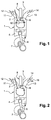
- a combustion engine comprises several combustion chambers 1, each equipped with an intake valve 2, an exhaust valve 3 and a removable piston 4, driven by a rod 6 mounted articulated on a crankshaft 7.
- An injection device 8 having an injection nozzle 9 and placed in each chamber 1 in a central position, makes it possible to distribute fuel 10 homogeneously in each of said chambers 1.
- inlet 2 can be controlled to open or close an intake duct 11 for conveying fresh air into each chamber 1 in the direction indicated by the arrow 12, and the exhaust valve 3 can be controlled to open or closing an exhaust duct 13 to exhaust the exhaust gas to the particulate filter, in the direction indicated by the arrow 14.
- the two-stroke cycle of a diesel engine in a motor vehicle differs from a four-stroke cycle because it is performed in just one crankshaft revolution instead of two for a four-stroke cycle. Since the phases of a two-stroke cycle and a four-stroke cycle are similar, namely, an intake phase, an exhaust phase, a compression phase, and a relaxation phase, the time range in particular to perform the intake and exhaust phases are actually reduced and must therefore be superimposed.
- the recovery phase of these two phases which corresponds to a simultaneous opening of each intake valve 2 and each exhaust valve 3, is the phase or the sweeping step.
- a regeneration method of a particulate filter according to the invention relates to a two-stroke diesel engine, and comprises a fuel injection step 10, which may for example consist of diesel fuel, during the step of sweeping for which each intake valve 2 and each exhaust valve 3 respectively open the intake duct 11 and the exhaust duct 13 of simultaneous way.
- the injection time is less than the total duration of the scanning step.
- a part of the gas oil injected during this scavenging step is carried by the exhaust duct 13, as indicated by the arrow 15, being closely connected to the flow of exhaust gas represented by the arrow 14.
- This part exhaust gas oil will burn in the exhaust gas and cause destruction of the particles and soot stagnant in said filter, by means of an increase in temperature.
- a residue of diesel fuel injected remains locked in chamber 1 and will participate in the combustion phase of the next cycle.
Landscapes
- Engineering & Computer Science (AREA)
- Chemical & Material Sciences (AREA)
- Combustion & Propulsion (AREA)
- Mechanical Engineering (AREA)
- General Engineering & Computer Science (AREA)
- Processes For Solid Components From Exhaust (AREA)
- Electrical Control Of Air Or Fuel Supplied To Internal-Combustion Engine (AREA)
Claims (9)
- Verfahren zur Regeneration eines Partikelfilters eines Zweitaktmotors eines Kraftfahrzeugs, wobei der Motor mindestens eine Verbrennungskammer (1) aufweist, die mindestens ein Einlassorgan (2) und mindestens ein Auslassorgan (3) aufweist, wobei der Betriebszyklus des Motors einen ersten Schritt des Kraftstoffeinspritzens (10) aufweist, um die Verbrennungsphase in jeder Kammer (1) zu gewährleisten, der von einem Schritt des Spülens gefolgt ist, während dem jedes Einlassorgan (2) und jedes Auslassorgan (3) in offener Position ist, dadurch gekennzeichnet, dass es einen Schritt des Kraftstoffeinspritzens (10) während des Schrittes des Spülens aufweist.
- Verfahren nach Anspruch 1, dadurch gekennzeichnet, dass jede Verbrennungskammer (1) mit einer einzigen Kraftstoffeinspritzvorrichtung (8) ausgestattet ist, um das Kraftstoffeinspritzen (10) während des Schrittes des Spülens und während des ersten Schrittes des Einspritzens durchzuführen.
- Verfahren nach Anspruch 2, dadurch gekennzeichnet, dass die Kraftstoffeinspritzvorrichtung (8) eine zentrale Düse (9) besitzt, die es ermöglicht, den Kraftstoff (10) in jeder Kammer (1) homogen zu diffundieren.
- Verfahren nach einem der Ansprüche 1 oder 2, dadurch gekennzeichnet, dass der Schritt des Kraftstoffeinspritzens (10) während des Schrittes des Spülens von dem ersten Schritt des Einspritzens getrennt ist.
- Verfahren nach einem der Ansprüche 1 bis 4, dadurch gekennzeichnet, dass der Schritt des Kraftstoffeinspritzens (10) während des Schrittes des Spülens eine kürzere Dauer als jene des ersten Schrittes des Einspritzens aufweist.
- Verfahren nach einem der Ansprüche 1 bis 5, dadurch gekennzeichnet, dass die Menge des Kraftstoffes (10), die während des Schrittes des Spülens eingespritzt wird, geringer als die Menge ist, die während des ersten Schrittes eingespritzt wird.
- Verfahren nach einem der Ansprüche 1 bis 6, dadurch gekennzeichnet, dass der Kraftstoff (10) Dieselkraftstoff ist.
- Verfahren nach Anspruch 1, dadurch gekennzeichnet, dass jede Kammer (1) eine erste Einspritzvorrichtung, um die erste Phase des Einspritzens zu gewährleisten, und eine zweite Einspritzvorrichtung besitzt, um das Kraftstoffeinspritzen (10) während der Phase des Spülens durchzuführen.
- Verfahren nach einem der Ansprüche 1 bis 8, dadurch gekennzeichnet, dass der Schritt des Kraftstoffeinspritzens während des Schrittes des Spülens mit einer geringeren Häufigkeit als jene des ersten Schrittes des Einspritzens durchgeführt wird.
Applications Claiming Priority (2)
| Application Number | Priority Date | Filing Date | Title |
|---|---|---|---|
| FR1250296A FR2985542B1 (fr) | 2012-01-11 | 2012-01-11 | Procede de regeneration d'un filtre a particules |
| PCT/EP2012/072249 WO2013104450A1 (fr) | 2012-01-11 | 2012-11-09 | Procede de regeneration d'un filtre a particules |
Publications (2)
| Publication Number | Publication Date |
|---|---|
| EP2802759A1 EP2802759A1 (de) | 2014-11-19 |
| EP2802759B1 true EP2802759B1 (de) | 2016-05-18 |
Family
ID=47143923
Family Applications (1)
| Application Number | Title | Priority Date | Filing Date |
|---|---|---|---|
| EP12783229.3A Active EP2802759B1 (de) | 2012-01-11 | 2012-11-09 | Verfahren zur steuerung eines partikelfilters |
Country Status (3)
| Country | Link |
|---|---|
| EP (1) | EP2802759B1 (de) |
| FR (1) | FR2985542B1 (de) |
| WO (1) | WO2013104450A1 (de) |
Cited By (1)
| Publication number | Priority date | Publication date | Assignee | Title |
|---|---|---|---|---|
| CN109113886A (zh) * | 2017-06-23 | 2019-01-01 | 曼能解决方案(曼能解决方案德国股份公司)分公司 | 大型涡轮增压二冲程压燃式内燃发动机及其操作方法 |
Family Cites Families (5)
| Publication number | Priority date | Publication date | Assignee | Title |
|---|---|---|---|---|
| DE19926138A1 (de) * | 1999-06-09 | 2000-12-14 | Volkswagen Ag | Verfahren und Vorrichtung zum Reinigen des Abgases einer Brennkraftmaschine, insbesondere einer Diesel-Brennkraftmaschine |
| US6826905B2 (en) * | 2002-06-04 | 2004-12-07 | International Engine Intellectual Property Company, Llc | Control strategy for regenerating a particulate filter in an exhaust system of an engine having a variable valve actuation mechanism |
| US7832197B2 (en) * | 2005-09-20 | 2010-11-16 | Ford Global Technologies, Llc | System and method for reducing NOx emissions in an apparatus having a diesel engine |
| US8132546B2 (en) * | 2008-05-08 | 2012-03-13 | Ford Global Technologies, Llc | Control strategy for multi-stroke engine system |
| US8359839B2 (en) * | 2009-09-29 | 2013-01-29 | Ford Global Technologies, Llc | System and method for regenerating a particulate filter for a direct injection engine |
-
2012
- 2012-01-11 FR FR1250296A patent/FR2985542B1/fr not_active Expired - Fee Related
- 2012-11-09 WO PCT/EP2012/072249 patent/WO2013104450A1/fr not_active Ceased
- 2012-11-09 EP EP12783229.3A patent/EP2802759B1/de active Active
Non-Patent Citations (1)
| Title |
|---|
| None * |
Cited By (2)
| Publication number | Priority date | Publication date | Assignee | Title |
|---|---|---|---|---|
| CN109113886A (zh) * | 2017-06-23 | 2019-01-01 | 曼能解决方案(曼能解决方案德国股份公司)分公司 | 大型涡轮增压二冲程压燃式内燃发动机及其操作方法 |
| CN109113886B (zh) * | 2017-06-23 | 2021-12-31 | 曼能解决方案(曼能解决方案德国股份公司)分公司 | 大型涡轮增压二冲程压燃式内燃发动机及其操作方法 |
Also Published As
| Publication number | Publication date |
|---|---|
| FR2985542B1 (fr) | 2014-02-07 |
| FR2985542A1 (fr) | 2013-07-12 |
| WO2013104450A1 (fr) | 2013-07-18 |
| EP2802759A1 (de) | 2014-11-19 |
Similar Documents
| Publication | Publication Date | Title |
|---|---|---|
| FR2926850A1 (fr) | Procede de balayage des gaz brules residuels avec une double levee de soupape d'admission d'un moteur a combustion interne suralimente a injection directe, notamment de type diesel | |
| EP2129891A2 (de) | Aufgeladener verbrennungsmotor | |
| EP2802759B1 (de) | Verfahren zur steuerung eines partikelfilters | |
| EP1965057B1 (de) | Verfahren zur Verbesserung der Verdampfung des Kraftstoffs für einen Dieselmotor mit Direkteinspritzung | |
| EP0961880B1 (de) | Verfahren und vorrichtung zum regenerieren eines adsorptionsfilters für eine brennkraftmaschine mit direkteinspritzung | |
| EP2166198B1 (de) | Verfahren zur Regelung der Ein- und Auslassventilsteuerung einer Brennkraftmaschine, bei welcher zumindest ein Zylinder abgeschaltet werden kann und Motor, der nach diesem Verfahren betrieben wird | |
| FR2856435A1 (fr) | Moteur suralimente a combustion interne a injection indirecte a balayage de gaz brules et procede d'alimentation en air suralimente pour un tel moteur | |
| EP1877657B1 (de) | Verfahren zur steuerung eines fahrzeugmotors zur regelung der temperatur eines partikelfilters | |
| EP1807610B1 (de) | Vorrichtung zur regenerierung eines in eine abgasanlage einer brennkraftmaschine eines kraftfahrzeugs integrierten abgasbehandlungssystems | |
| WO2006045982A2 (fr) | Procédé de commande d'un moteur de véhicule via des lois de levée de soupapes | |
| FR3015562A1 (fr) | Ensemble comprenant un moteur thermique et un compresseur electrique configure pour faire du balayage des gaz brules residuels | |
| FR2885390A1 (fr) | Procede de regeneration d'un filtre a particules pour moteur , par injection de carburant. | |
| FR3152292A1 (fr) | Procédé et dispositif de contrôle d’un moteur à allumage commandé pour l’augmentation de l’efficacité d’un filtre à particules | |
| FR2882571A1 (fr) | Dispositif de filtrage de particules pour moteur diesel avec recyclage de gaz d'echappement | |
| FR2928686A3 (fr) | Procede de regeneration d'un dispositif de post-traitement d'un systeme d'echappement d'un moteur a combustion interne | |
| FR2853690A1 (fr) | Dispositif et methode de depollution de gaz d'echappement d'un moteur suralimente a combustion interne | |
| FR2910063A1 (fr) | Procede d'injection dans un moteur a combustion interne alternatif a cycle diesel | |
| EP2562400A1 (de) | Verfahren zur Regeneration eines Partikelfilters einer Brennkraftmaschine | |
| FR2909706A1 (fr) | Procede d'injection retardee d'un jet de carburant oriente vers la tete d'une soupape d'echappement et application d'un tel procede a la regeneration d'un dispositif de depollution | |
| FR2913066A1 (fr) | Procede pour faciliter la vaporisation d'un carburant d'un moteur a combustion interne | |
| FR2978983A1 (fr) | Procede et dispositif de regeneration d'un filtre a particules dans la ligne d'echappement d'un moteur thermique d'un vehicule hybride | |
| EP1703105B1 (de) | Vorrichtung zur Regenerierung eines NOX-Speicherkatalysators im Abgasstrans eines Kraftfahrzeugmotors | |
| FR3020411A1 (fr) | Procede de regeneration d'un filtre a particules impregne par paliers de temperature | |
| FR2975133A1 (fr) | Procede pour controler l'admission et l'echappement d'au moins un cylindre desactive d'un moteur a combustion interne et dispositif utilisant un tel procede | |
| FR2882102A1 (fr) | Systeme d'aide a la regeneration de moyens de depollution integres dans une ligne d'echappement d'un moteur de vehicule |
Legal Events
| Date | Code | Title | Description |
|---|---|---|---|
| PUAI | Public reference made under article 153(3) epc to a published international application that has entered the european phase |
Free format text: ORIGINAL CODE: 0009012 |
|
| 17P | Request for examination filed |
Effective date: 20140429 |
|
| AK | Designated contracting states |
Kind code of ref document: A1 Designated state(s): AL AT BE BG CH CY CZ DE DK EE ES FI FR GB GR HR HU IE IS IT LI LT LU LV MC MK MT NL NO PL PT RO RS SE SI SK SM TR |
|
| DAX | Request for extension of the european patent (deleted) | ||
| GRAP | Despatch of communication of intention to grant a patent |
Free format text: ORIGINAL CODE: EPIDOSNIGR1 |
|
| INTG | Intention to grant announced |
Effective date: 20160209 |
|
| GRAS | Grant fee paid |
Free format text: ORIGINAL CODE: EPIDOSNIGR3 |
|
| GRAA | (expected) grant |
Free format text: ORIGINAL CODE: 0009210 |
|
| AK | Designated contracting states |
Kind code of ref document: B1 Designated state(s): AL AT BE BG CH CY CZ DE DK EE ES FI FR GB GR HR HU IE IS IT LI LT LU LV MC MK MT NL NO PL PT RO RS SE SI SK SM TR |
|
| REG | Reference to a national code |
Ref country code: GB Ref legal event code: FG4D Free format text: NOT ENGLISH |
|
| REG | Reference to a national code |
Ref country code: CH Ref legal event code: EP |
|
| REG | Reference to a national code |
Ref country code: IE Ref legal event code: FG4D Free format text: LANGUAGE OF EP DOCUMENT: FRENCH Ref country code: AT Ref legal event code: REF Ref document number: 800698 Country of ref document: AT Kind code of ref document: T Effective date: 20160615 |
|
| REG | Reference to a national code |
Ref country code: DE Ref legal event code: R096 Ref document number: 602012018703 Country of ref document: DE |
|
| REG | Reference to a national code |
Ref country code: NL Ref legal event code: MP Effective date: 20160518 |
|
| REG | Reference to a national code |
Ref country code: LT Ref legal event code: MG4D |
|
| PG25 | Lapsed in a contracting state [announced via postgrant information from national office to epo] |
Ref country code: NL Free format text: LAPSE BECAUSE OF FAILURE TO SUBMIT A TRANSLATION OF THE DESCRIPTION OR TO PAY THE FEE WITHIN THE PRESCRIBED TIME-LIMIT Effective date: 20160518 Ref country code: FI Free format text: LAPSE BECAUSE OF FAILURE TO SUBMIT A TRANSLATION OF THE DESCRIPTION OR TO PAY THE FEE WITHIN THE PRESCRIBED TIME-LIMIT Effective date: 20160518 Ref country code: NO Free format text: LAPSE BECAUSE OF FAILURE TO SUBMIT A TRANSLATION OF THE DESCRIPTION OR TO PAY THE FEE WITHIN THE PRESCRIBED TIME-LIMIT Effective date: 20160818 Ref country code: LT Free format text: LAPSE BECAUSE OF FAILURE TO SUBMIT A TRANSLATION OF THE DESCRIPTION OR TO PAY THE FEE WITHIN THE PRESCRIBED TIME-LIMIT Effective date: 20160518 |
|
| REG | Reference to a national code |
Ref country code: AT Ref legal event code: MK05 Ref document number: 800698 Country of ref document: AT Kind code of ref document: T Effective date: 20160518 |
|
| REG | Reference to a national code |
Ref country code: FR Ref legal event code: PLFP Year of fee payment: 5 |
|
| PG25 | Lapsed in a contracting state [announced via postgrant information from national office to epo] |
Ref country code: RS Free format text: LAPSE BECAUSE OF FAILURE TO SUBMIT A TRANSLATION OF THE DESCRIPTION OR TO PAY THE FEE WITHIN THE PRESCRIBED TIME-LIMIT Effective date: 20160518 Ref country code: GR Free format text: LAPSE BECAUSE OF FAILURE TO SUBMIT A TRANSLATION OF THE DESCRIPTION OR TO PAY THE FEE WITHIN THE PRESCRIBED TIME-LIMIT Effective date: 20160819 Ref country code: PT Free format text: LAPSE BECAUSE OF FAILURE TO SUBMIT A TRANSLATION OF THE DESCRIPTION OR TO PAY THE FEE WITHIN THE PRESCRIBED TIME-LIMIT Effective date: 20160919 Ref country code: HR Free format text: LAPSE BECAUSE OF FAILURE TO SUBMIT A TRANSLATION OF THE DESCRIPTION OR TO PAY THE FEE WITHIN THE PRESCRIBED TIME-LIMIT Effective date: 20160518 Ref country code: LV Free format text: LAPSE BECAUSE OF FAILURE TO SUBMIT A TRANSLATION OF THE DESCRIPTION OR TO PAY THE FEE WITHIN THE PRESCRIBED TIME-LIMIT Effective date: 20160518 Ref country code: SE Free format text: LAPSE BECAUSE OF FAILURE TO SUBMIT A TRANSLATION OF THE DESCRIPTION OR TO PAY THE FEE WITHIN THE PRESCRIBED TIME-LIMIT Effective date: 20160518 |
|
| PG25 | Lapsed in a contracting state [announced via postgrant information from national office to epo] |
Ref country code: IT Free format text: LAPSE BECAUSE OF FAILURE TO SUBMIT A TRANSLATION OF THE DESCRIPTION OR TO PAY THE FEE WITHIN THE PRESCRIBED TIME-LIMIT Effective date: 20160518 |
|
| PG25 | Lapsed in a contracting state [announced via postgrant information from national office to epo] |
Ref country code: SK Free format text: LAPSE BECAUSE OF FAILURE TO SUBMIT A TRANSLATION OF THE DESCRIPTION OR TO PAY THE FEE WITHIN THE PRESCRIBED TIME-LIMIT Effective date: 20160518 Ref country code: DK Free format text: LAPSE BECAUSE OF FAILURE TO SUBMIT A TRANSLATION OF THE DESCRIPTION OR TO PAY THE FEE WITHIN THE PRESCRIBED TIME-LIMIT Effective date: 20160518 Ref country code: RO Free format text: LAPSE BECAUSE OF FAILURE TO SUBMIT A TRANSLATION OF THE DESCRIPTION OR TO PAY THE FEE WITHIN THE PRESCRIBED TIME-LIMIT Effective date: 20160518 Ref country code: CZ Free format text: LAPSE BECAUSE OF FAILURE TO SUBMIT A TRANSLATION OF THE DESCRIPTION OR TO PAY THE FEE WITHIN THE PRESCRIBED TIME-LIMIT Effective date: 20160518 Ref country code: EE Free format text: LAPSE BECAUSE OF FAILURE TO SUBMIT A TRANSLATION OF THE DESCRIPTION OR TO PAY THE FEE WITHIN THE PRESCRIBED TIME-LIMIT Effective date: 20160518 |
|
| REG | Reference to a national code |
Ref country code: DE Ref legal event code: R097 Ref document number: 602012018703 Country of ref document: DE |
|
| PG25 | Lapsed in a contracting state [announced via postgrant information from national office to epo] |
Ref country code: AT Free format text: LAPSE BECAUSE OF FAILURE TO SUBMIT A TRANSLATION OF THE DESCRIPTION OR TO PAY THE FEE WITHIN THE PRESCRIBED TIME-LIMIT Effective date: 20160518 Ref country code: PL Free format text: LAPSE BECAUSE OF FAILURE TO SUBMIT A TRANSLATION OF THE DESCRIPTION OR TO PAY THE FEE WITHIN THE PRESCRIBED TIME-LIMIT Effective date: 20160518 Ref country code: SM Free format text: LAPSE BECAUSE OF FAILURE TO SUBMIT A TRANSLATION OF THE DESCRIPTION OR TO PAY THE FEE WITHIN THE PRESCRIBED TIME-LIMIT Effective date: 20160518 Ref country code: BE Free format text: LAPSE BECAUSE OF NON-PAYMENT OF DUE FEES Effective date: 20161130 |
|
| PLBE | No opposition filed within time limit |
Free format text: ORIGINAL CODE: 0009261 |
|
| STAA | Information on the status of an ep patent application or granted ep patent |
Free format text: STATUS: NO OPPOSITION FILED WITHIN TIME LIMIT |
|
| 26N | No opposition filed |
Effective date: 20170221 |
|
| PG25 | Lapsed in a contracting state [announced via postgrant information from national office to epo] |
Ref country code: SI Free format text: LAPSE BECAUSE OF FAILURE TO SUBMIT A TRANSLATION OF THE DESCRIPTION OR TO PAY THE FEE WITHIN THE PRESCRIBED TIME-LIMIT Effective date: 20160518 |
|
| REG | Reference to a national code |
Ref country code: CH Ref legal event code: PL |
|
| PG25 | Lapsed in a contracting state [announced via postgrant information from national office to epo] |
Ref country code: CH Free format text: LAPSE BECAUSE OF NON-PAYMENT OF DUE FEES Effective date: 20161130 Ref country code: LI Free format text: LAPSE BECAUSE OF NON-PAYMENT OF DUE FEES Effective date: 20161130 |
|
| REG | Reference to a national code |
Ref country code: IE Ref legal event code: MM4A |
|
| PG25 | Lapsed in a contracting state [announced via postgrant information from national office to epo] |
Ref country code: LU Free format text: LAPSE BECAUSE OF NON-PAYMENT OF DUE FEES Effective date: 20161130 |
|
| REG | Reference to a national code |
Ref country code: FR Ref legal event code: PLFP Year of fee payment: 6 |
|
| PG25 | Lapsed in a contracting state [announced via postgrant information from national office to epo] |
Ref country code: IE Free format text: LAPSE BECAUSE OF NON-PAYMENT OF DUE FEES Effective date: 20161109 |
|
| REG | Reference to a national code |
Ref country code: BE Ref legal event code: MM Effective date: 20161130 |
|
| PG25 | Lapsed in a contracting state [announced via postgrant information from national office to epo] |
Ref country code: ES Free format text: LAPSE BECAUSE OF FAILURE TO SUBMIT A TRANSLATION OF THE DESCRIPTION OR TO PAY THE FEE WITHIN THE PRESCRIBED TIME-LIMIT Effective date: 20160518 Ref country code: HU Free format text: LAPSE BECAUSE OF FAILURE TO SUBMIT A TRANSLATION OF THE DESCRIPTION OR TO PAY THE FEE WITHIN THE PRESCRIBED TIME-LIMIT; INVALID AB INITIO Effective date: 20121109 |
|
| PG25 | Lapsed in a contracting state [announced via postgrant information from national office to epo] |
Ref country code: MC Free format text: LAPSE BECAUSE OF FAILURE TO SUBMIT A TRANSLATION OF THE DESCRIPTION OR TO PAY THE FEE WITHIN THE PRESCRIBED TIME-LIMIT Effective date: 20160518 Ref country code: IS Free format text: LAPSE BECAUSE OF FAILURE TO SUBMIT A TRANSLATION OF THE DESCRIPTION OR TO PAY THE FEE WITHIN THE PRESCRIBED TIME-LIMIT Effective date: 20160518 Ref country code: MK Free format text: LAPSE BECAUSE OF FAILURE TO SUBMIT A TRANSLATION OF THE DESCRIPTION OR TO PAY THE FEE WITHIN THE PRESCRIBED TIME-LIMIT Effective date: 20160518 Ref country code: CY Free format text: LAPSE BECAUSE OF FAILURE TO SUBMIT A TRANSLATION OF THE DESCRIPTION OR TO PAY THE FEE WITHIN THE PRESCRIBED TIME-LIMIT Effective date: 20160518 |
|
| PG25 | Lapsed in a contracting state [announced via postgrant information from national office to epo] |
Ref country code: BG Free format text: LAPSE BECAUSE OF FAILURE TO SUBMIT A TRANSLATION OF THE DESCRIPTION OR TO PAY THE FEE WITHIN THE PRESCRIBED TIME-LIMIT Effective date: 20160518 |
|
| PG25 | Lapsed in a contracting state [announced via postgrant information from national office to epo] |
Ref country code: MT Free format text: LAPSE BECAUSE OF FAILURE TO SUBMIT A TRANSLATION OF THE DESCRIPTION OR TO PAY THE FEE WITHIN THE PRESCRIBED TIME-LIMIT Effective date: 20160518 |
|
| PG25 | Lapsed in a contracting state [announced via postgrant information from national office to epo] |
Ref country code: TR Free format text: LAPSE BECAUSE OF FAILURE TO SUBMIT A TRANSLATION OF THE DESCRIPTION OR TO PAY THE FEE WITHIN THE PRESCRIBED TIME-LIMIT Effective date: 20160518 Ref country code: AL Free format text: LAPSE BECAUSE OF FAILURE TO SUBMIT A TRANSLATION OF THE DESCRIPTION OR TO PAY THE FEE WITHIN THE PRESCRIBED TIME-LIMIT Effective date: 20160518 |
|
| P01 | Opt-out of the competence of the unified patent court (upc) registered |
Effective date: 20230608 |
|
| REG | Reference to a national code |
Ref country code: GB Ref legal event code: 732E Free format text: REGISTERED BETWEEN 20231228 AND 20240103 |
|
| REG | Reference to a national code |
Ref country code: DE Ref legal event code: R081 Ref document number: 602012018703 Country of ref document: DE Owner name: NEW H POWERTRAIN HOLDING, S.L.U., ES Free format text: FORMER OWNER: RENAULT S.A.S., BOULOGNE-BILLANCOURT, FR |
|
| PGFP | Annual fee paid to national office [announced via postgrant information from national office to epo] |
Ref country code: DE Payment date: 20251119 Year of fee payment: 14 |
|
| PGFP | Annual fee paid to national office [announced via postgrant information from national office to epo] |
Ref country code: GB Payment date: 20251121 Year of fee payment: 14 |
|
| PGFP | Annual fee paid to national office [announced via postgrant information from national office to epo] |
Ref country code: FR Payment date: 20251125 Year of fee payment: 14 |