EP2802181B1 - Determination method and device for resources in physical uplink control channel - Google Patents
Determination method and device for resources in physical uplink control channel Download PDFInfo
- Publication number
- EP2802181B1 EP2802181B1 EP13810064.9A EP13810064A EP2802181B1 EP 2802181 B1 EP2802181 B1 EP 2802181B1 EP 13810064 A EP13810064 A EP 13810064A EP 2802181 B1 EP2802181 B1 EP 2802181B1
- Authority
- EP
- European Patent Office
- Prior art keywords
- epdcch
- pucch
- ecce
- index
- physical resource
- Prior art date
- Legal status (The legal status is an assumption and is not a legal conclusion. Google has not performed a legal analysis and makes no representation as to the accuracy of the status listed.)
- Active
Links
- 238000000034 method Methods 0.000 title claims description 69
- 230000005540 biological transmission Effects 0.000 claims description 169
- 230000011664 signaling Effects 0.000 claims description 97
- 102100036409 Activated CDC42 kinase 1 Human genes 0.000 claims description 17
- 101000741965 Homo sapiens Inactive tyrosine-protein kinase PRAG1 Proteins 0.000 claims description 17
- 102100038659 Inactive tyrosine-protein kinase PRAG1 Human genes 0.000 claims description 17
- 238000005516 engineering process Methods 0.000 description 12
- 238000013507 mapping Methods 0.000 description 9
- 238000010586 diagram Methods 0.000 description 7
- TVEXGJYMHHTVKP-UHFFFAOYSA-N 6-oxabicyclo[3.2.1]oct-3-en-7-one Chemical compound C1C2C(=O)OC1C=CC2 TVEXGJYMHHTVKP-UHFFFAOYSA-N 0.000 description 6
- 239000013256 coordination polymer Substances 0.000 description 5
- 238000004891 communication Methods 0.000 description 2
- 125000004122 cyclic group Chemical group 0.000 description 2
- 238000013461 design Methods 0.000 description 2
- 238000012790 confirmation Methods 0.000 description 1
- 238000001514 detection method Methods 0.000 description 1
- 238000011161 development Methods 0.000 description 1
- 230000007774 longterm Effects 0.000 description 1
- 238000012986 modification Methods 0.000 description 1
- 230000004048 modification Effects 0.000 description 1
- 230000003252 repetitive effect Effects 0.000 description 1
- 238000013468 resource allocation Methods 0.000 description 1
- 230000004044 response Effects 0.000 description 1
Images

Classifications
-
- H—ELECTRICITY
- H04—ELECTRIC COMMUNICATION TECHNIQUE
- H04L—TRANSMISSION OF DIGITAL INFORMATION, e.g. TELEGRAPHIC COMMUNICATION
- H04L1/00—Arrangements for detecting or preventing errors in the information received
- H04L1/12—Arrangements for detecting or preventing errors in the information received by using return channel
- H04L1/16—Arrangements for detecting or preventing errors in the information received by using return channel in which the return channel carries supervisory signals, e.g. repetition request signals
- H04L1/18—Automatic repetition systems, e.g. Van Duuren systems
- H04L1/1829—Arrangements specially adapted for the receiver end
- H04L1/1861—Physical mapping arrangements
-
- H—ELECTRICITY
- H04—ELECTRIC COMMUNICATION TECHNIQUE
- H04W—WIRELESS COMMUNICATION NETWORKS
- H04W72/00—Local resource management
- H04W72/20—Control channels or signalling for resource management
- H04W72/21—Control channels or signalling for resource management in the uplink direction of a wireless link, i.e. towards the network
-
- H—ELECTRICITY
- H04—ELECTRIC COMMUNICATION TECHNIQUE
- H04L—TRANSMISSION OF DIGITAL INFORMATION, e.g. TELEGRAPHIC COMMUNICATION
- H04L5/00—Arrangements affording multiple use of the transmission path
- H04L5/003—Arrangements for allocating sub-channels of the transmission path
- H04L5/0053—Allocation of signaling, i.e. of overhead other than pilot signals
- H04L5/0055—Physical resource allocation for ACK/NACK
-
- H—ELECTRICITY
- H04—ELECTRIC COMMUNICATION TECHNIQUE
- H04W—WIRELESS COMMUNICATION NETWORKS
- H04W72/00—Local resource management
-
- H—ELECTRICITY
- H04—ELECTRIC COMMUNICATION TECHNIQUE
- H04W—WIRELESS COMMUNICATION NETWORKS
- H04W72/00—Local resource management
- H04W72/20—Control channels or signalling for resource management
- H04W72/23—Control channels or signalling for resource management in the downlink direction of a wireless link, i.e. towards a terminal
-
- H—ELECTRICITY
- H04—ELECTRIC COMMUNICATION TECHNIQUE
- H04L—TRANSMISSION OF DIGITAL INFORMATION, e.g. TELEGRAPHIC COMMUNICATION
- H04L1/00—Arrangements for detecting or preventing errors in the information received
- H04L1/12—Arrangements for detecting or preventing errors in the information received by using return channel
- H04L1/16—Arrangements for detecting or preventing errors in the information received by using return channel in which the return channel carries supervisory signals, e.g. repetition request signals
- H04L1/1607—Details of the supervisory signal
-
- H—ELECTRICITY
- H04—ELECTRIC COMMUNICATION TECHNIQUE
- H04W—WIRELESS COMMUNICATION NETWORKS
- H04W72/00—Local resource management
- H04W72/12—Wireless traffic scheduling
Definitions
- the present document relates to the field of communications, and in particular, to a method and apparatus for determining resources in a Physical Uplink Control Channel (PUCCH) in a system.
- PUCCH Physical Uplink Control Channel
- Fig. 1 is a diagram of a frame structure of a Frequency Division Duplex (FDD) mode of a Long Term Evolution (LTE) system, and as shown in Fig. 1 , in the frame structure of the FDD mode, one 10ms-radio frame is comprised of 20 slots with a length of 0.5ms and numbered from 0 to 19, and slots 2i and 2i+1 constitute a subframe i with a length of 1ms.
- Fig. 2 is a diagram of a frame structure of a Time Division Duplex (TDD) mode of an LTE system, and as shown in Fig.
- TDD Time Division Duplex
- one 10ms radio frame is comprised of 2 half frames with a length of 5ms, each of which includes 5 subframes with a length of 1ms.
- Subframe i is defined as 2 slots 2i and 2i+1 with a length of 0.5ms.
- one slot includes 7 symbols with a length of 66.7us, wherein, a CP length of the first symbol is 5.12us, and a CP length of each of the remaining 6 symbols is 4.69us; and for an extended Cyclic Prefix, one slot includes 6 symbols, and a CP length of each of all symbols is 16.67us.
- a Physical Downlink Control Channel (PDCCH for short) for transmitting physical layer control signaling is generally configured to be transmitted on first N Orthogonal Frequency Division Multiplexing (OFDM) symbols of a subframe, and the N symbols are generally be referred to as a control signaling transmission region.
- OFDM Orthogonal Frequency Division Multiplexing
- the control signaling transmission region of the R8/9/10 is referred to as a first control signaling transmission region in the embodiments of the present document.
- CCE Control Channel Element
- REG Resource Element Group
- 9 REGs constitute one CCE, and each REG is comprised of multiple basic resource units of Resource Elements (REs).
- control signaling transmission resources allocated by a user are not localized, and bring out many difficulties to the implementation of the closed-loop precoding technology in a multi-antenna system, and therefore, only the diversity technology can be used in the control signaling region, and it is difficult to use the closed-loop precoding technology.
- the primary reason is that it is difficult to design the demodulation reference signal and channel state information feedback in the first precoding region, and therefore, the control signaling in all the existing releases only support non-localized resource transmission and diversity technologies.
- control signaling transmission resources of the same User Equipment may be localized time-frequency resources, to support the closed-loop precoding technology, and enhance the transmission performance of the control information.
- the control signaling regions of the new and old releases are as shown in Fig. 3 .
- the second control signaling transmission region can reuse a Demodulation Reference Signal (DMRS) in R10 to demodulate the control signaling, which well supports the precoding technology.
- DMRS Demodulation Reference Signal
- the second control signaling transmission region is in units of Resource Blocks (RBs), which can well perform interference coordination.
- the DMRS can also support the open-loop diversity technology, for example, a Space-Frequency Block Coding (SFBC) technology.
- SFBC Space-Frequency Block Coding
- one RE is one subcarrier on one OFDM symbol
- one downlink physical RB is comprised of 12 localized subcarriers and 14 (12 when an extended CP is used) localized OFDM symbols
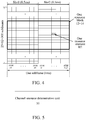
- the RB is 180kHz in the frequency domain and is generally a time length of one slot in the time domain, as shown in Fig. 4 (one 5M system).
- the LTE/LTE-A system allocates the resources with RB being a basic unit.
- n PUCCH 1 n CCE + N PUCCH 1 , wherein, n PUCCH 1 is a PUCCH resource index for transmitting a HARQ-ACK by a user, n CCE is a first CCE index for transmitting the PDCCH, and N PUCCH 1 is configured by a higher layer.
- resource indexes for transmitting the PUCCH carrying the HARQ-ACK in the uplink are obtained after block interleaving the CCE indexes corresponding to the PDCCH allocated to the user on the scheduled downlink subframes.
- a concept of feedback window is defined. The feedback window is all downlink subframes corresponding to uplink subframes (it should be illustrated that "corresponding" here refers to all these downlink subframes feed back confirmation information in the uplink subframes).
- the number of downlink subframes is greater than the number of uplink subframes in one radio frame
- feedback information of multiple downlink subframes may be transmitted in the same uplink subframe.
- Such multiple downlink subframes corresponding to one uplink subframe are referred to as a feedback window.
- n PUCCH 1 is configured by a higher layer and is decided by table one.
- Table one illustrates a relationship between PUCCH resource indexes and signaling.
- Table one Relationship between PUCCH resource indexes and signaling Transmit Power Control (TPC) domain value n PUCCH 1 '00' First PUCCH resource index configured by a higher layer '01' Second PUCCH resource index configured by a higher layer '10' Third PUCCH resource index configured by a higher layer '11' Fourth PUCCH resource index configured by a higher layer
- n PUCCH 1 of the PDSCH is determined by one of four resources configured by a higher layer indicated by a TPC domain.
- an Enhanced PDCCH (ePDCCH) is introduced to enhance the performance of the PDCCH, and at the same time, a new PDCCH transmission region is introduced, and an Enhanced Control Channel Element (eCCE) for carrying an ePDCCH is defined.
- ePDCCH Enhanced PDCCH
- eCCE Enhanced Control Channel Element
- LG ELECTRONICS "Discussion on PUCCH Resource for ePDCCH", 3GPP DRAFT, R1-122314, vol. RAN WG1, no. Prague, Czech Republic, 12 May 2012 (2012-05-12 ), and relevant technologies are also known from HUWEI ET AL: “Need of multiplexing localized and distributed transmission in one PRB pair", 3GPP DRAFT, R1-121965, vol. RAN WG1, no. Prague, Czech Republic, 12 May 2012 (2012-05-12 ), SAMSUNG: "HARQ-ACK PUCCH Resources in Response to ePDCCH Detections"; R1-122259, vol.
- NOKIA SIEMENS NETWORKS ET AL " HARQ-ACK resource allocation for data scheduled via ePDCCH” ; R1-122428, vol. RAN WG1, 12 May 2012 (2012-05-12 ) and NOKIA ET AL: "Multiplexing of ePDCCH for different users” ; R1-121288, vol. RAN WG1, 20 March 2012 (2012-03-20 ).
- the embodiments of the present document provide a method and apparatus for determining resources in a physical uplink control channel to at least solve the above problem as defined in the attach independent claims 1 and 8.
- an ePDCCH is introduced to enhance the performance of the PDCCH, and at the same time, a new PDCCH transmission region is introduced.
- a method for obtaining channel resources of the PUCCH for transmitting the ACK/NACK corresponding to the PDSCH of the ePDCCH is provided in the present embodiment. The method ensures normal operation of the HARQ process corresponding to the ePDCCH, and ensures the compatibility between an LTE-Advanced system and an LTE Release-8 system, thereby enabling an LTE-Advanced terminal to obtain a maximum frequency selectivity gain. It should be illustrated that systems in which the following embodiments and preferred implementations thereof are applied are not limited to the LTE-Advanced system.
- the embodiments of the present document provide a method for determining resources in a PUCCH, comprising: an apparatus determining a channel resource index n PUCCH 1 of the PUCCH according to physical resources of an ePDCCH, wherein, the PUCCH is used for carrying positive acknowledgement/negative acknowledgement (ACK/NACK) information about a PDSCH indicated by the ePDCCH; and the physical resources of the ePDCCH comprise: any one or more of a physical resource block, an eCCE and an antenna port index.
- ACK/NACK positive acknowledgement/negative acknowledgement
- the apparatus is a terminal or a base station.
- the step of an apparatus determining a channel resource index n PUCCH 1 of the PUCCH according to physical resources of an ePDCCH comprises: determining an initial position N PUCCH Start of channel resources of the PUCCH, wherein,
- the initial position N PUCCH Start may also be 0, wherein, when multiple serving cells are configured, the above D represents a condition of a primary serving cell (or a primary component carrier) when the ePDCCH is in the primary serving cell; the initial position of the PUCCH Format 1a/1b resource is an initial position of the PUCCH Format 1a/1b resource on the primary serving cell in the uplink subframe where the PUCCH is located.
- N PUCCH Start s may be different or the same in different uplink sub frames.
- the initial positions of channel resources of the PUCCH corresponding to the ePDCCH in different transmission modes are the same or different, or the initial positions may also be independently configured.
- the initial position in a distributed transmission mode is N PUCCH 4
- the initial position in a localized transmission mode is N PUCCH 5 .
- the step of an apparatus determining a channel resource index n PUCCH 1 of the PUCCH according to physical resources of an ePDCCH comprises: determining an offset, wherein, the offset is determined according to any one or more of the following information: antenna port information of the ePDCCH, indication signaling, a transmission mode of the ePDCCH, a position of the ePDCCH in the physical resource block, an eCCE index corresponding to the ePDCCH, and an enhanced resource unit group index corresponding to the ePDCCH; or the offset is a fixed value, for example, 0 or other values except 0.
- a method for determining the offset is one of the following or a combination thereof.
- the step of an apparatus determining a channel resource index n PUCCH 1 of the PUCCH according to physical resources of an ePDCCH comprises:
- n PRB is determined by means of:
- the step of determining the n PRB according to the maximum or minimum D-eCCE index for carrying the ePDCCH comprises:
- n eCCE is determined by means of:
- the step of determining the n eCCE according to the maximum or minimum D-eCCE index for carrying the ePDCCH comprises:
- the method for numbering the physical resources of the ePDCCH comprises:
- numbers of the above physical resources are those on a subframe where the ePDCCH is located.
- the numbers of the physical resources are those on a serving cell and a subframe where the ePDCCH is located, wherein, the ePDCCH is located in a primary serving cell.
- an apparatus determines a channel resource index n PUCCH 1 of a PUCCH according to the renumbered physical resource block index n PRB where the ePDCCH is located and an offset, wherein, the maximum number of the uplink control channel resources corresponding to one physical resource block carrying the ePDCCH is h, n PRB and the offset are determined according to at least one of antenna port information used by the ePDCCH, a transmission mode of the ePDCCH, a position of the ePDCCH in the physical resource blocks, and indication signaling; and the PUCCH is used to carry ACK/NACK information of the PDSCH indicated by the ePDCCH.
- the step of the apparatus determining a channel resource index n PUCCH 1 of a PUCCH according to the physical resources of an ePDCCH comprises: the apparatus determining an initial position N PUCCH Start of channel resources of the PUCCH, wherein, the N PUCCH Start is an initial position N PUCCH 1 of the channel resources of the PUCCH corresponding to an existing PDCCH; or the N PUCCH Start is an initial position N PUCCH 1 of the channel resource of the PUCCH corresponding to the existing PDCCH plus a predefined value D, wherein, the D represents the maximum number of channel resources of the PUCCH corresponding to the PDCCH in uplink subframes where the PUCCH is located; or the D represents the number of CCEs in subframes where the ePDCCH is located; or the N PUCCH Start is the initial position N PUCCH 1 of the channel resources of the PUCCH corresponding to the existing PDCCH plus the pre
- the initial positions may be different or the same in different uplink subframes; the initial positions in different transmission modes may be the same or different (i.e., the initial positions are independently configured, for example, an initial position in the distributed transmission mode is N PUCCH 4 , and an initial position in a localized transmission mode is N PUCCH 5 ).
- the n PRB is determined according to the transmission mode of the ePDCCH; wherein, the transmission mode of the ePDCCH comprises a distributed transmission mode and a localized transmission mode;
- a method for renumbering the physical resource blocks of the ePDCCH includes the following modes.
- Physical resource blocks for transmitting the ePDCCH in a distributed transmission mode and physical resource blocks for transmitting the ePDCCH in a localized transmission mode share the same region; i.e., the configured physical resource blocks for transmitting the ePDCCH may be used to transmit the ePDCCH in a distributed transmission mode, and may also be used to transmit the ePDCCH in a localized transmission mode.
- the method for renumbering the physical resource blocks of the ePDCCH is to renumber the indexes of the configured physical resource blocks for transmitting the ePDCCH according to the sizes of the original physical resource block indexes.
- the physical resource blocks for transmitting the ePDCCH in a distributed transmission mode and the physical resource blocks for transmitting the ePDCCH in a localized transmission mode are configured respectively, and correspond to different regions.
- the method for renumbering the physical resource blocks of the ePDCCH is to firstly concatenate the physical resource blocks for transmitting the ePDCCH in a distributed transmission mode and the physical resource blocks for transmitting the ePDCCH in a localized transmission mode, and then renumber the physical resource blocks according to a concatenated order.
- the physical resource blocks for transmitting the ePDCCH in a distributed transmission mode and the physical resource blocks for transmitting the ePDCCH in a localized transmission mode are configured respectively, and correspond to different regions.
- the method for renumbering the physical resource blocks of the ePDCCH is to respectively renumber physical resource blocks for transmitting the ePDCCH in a distributed transmission mode and the physical resource blocks for transmitting the ePDCCH in a localized transmission mode in order.
- the physical resource block index n PRB is a renumbered maximum (or minimum) physical resource block index corresponding to the ePDCCH; and the method for renumbering the physical resource block indexes of the ePDCCH is to renumber the indexes of the configured physical resource blocks for transmitting the ePDCCH according to the sizes of the original physical resource block indexes.
- determining the physical resource block index n PRB according to the maximum (or minimum) D-eCCE index corresponding to the ePDCCH comprises the following methods.
- the method for determining the offset is described as follows.
- the offset value is determined according to the antenna port information used by the ePDCCH; and a range of the offset value is 0 to h-1; wherein, the antenna port information used by the ePDCCH includes antenna port indexes.
- the antenna port 7, antenna port 8, antenna port 9 and antenna port 10 correspond to offset values 0 to 3 one by one.
- an offset value corresponding to the antenna port 7 is 0, an offset value corresponding to the antenna port 8 is 1, an offset value corresponding to the antenna port 9 is 2, and an offset value corresponding to the antenna port 10 is 3, and the correspondence is not limited thereto; and the correspondence for different users may be the same or different.
- the antenna port indexes of the ePDCCH are antenna port 7 and antenna port 9, and a value of h is 4, then the antenna port 7 and antenna port 9 correspond to offset values 0 to 3.
- an offset value corresponding to the antenna port 7 is 0, and an offset value corresponding to the antenna port 9 is 2, or an offset value corresponding to the antenna port 7 is 1, and an offset value corresponding to the antenna port 9 is 3, and the correspondence is not limited thereto.
- the antenna port indexes of the ePDCCH are antenna port 7 and antenna port 8, and a value of h is 2, then the antenna port 7 and antenna port 8 correspond to offset values 0 to 1.
- an offset value corresponding to the antenna port 7 is 0, and an offset value corresponding to the antenna port 8 is 1, and the correspondence is not limited thereto.
- the antenna port information used by the ePDCCH includes antenna port indexes and initial sequence information corresponding to the antenna ports (an SCID and/or a virtual cell ID).
- the antenna port indexes of the ePDCCH are antenna port 7, antenna port 8, antenna port 9 and antenna port 10, and a value of h is 8, a value of the SCID is 0 or 1, and the virtual cell ID is x(0) or x(1), then the antenna port 7/8/9/10 with an SCID of 0 and the antenna port 7/8/9/10 with an SCID of 1 correspond to offset values 0 to 7 one by one; or the antenna port 7/8/9/10 with a virtual cell ID of x(0) and the antenna port 7/8/9/10 with a virtual cell ID of x(1) correspond to offset values 0 to 7 one by one; or the antenna port 7/8/9/10 with an SCID of 0 and a virtual cell ID of x(0) and the antenna port 7/8/9/10 with an SCID of 1 and a virtual cell ID of x(1) correspond to offset values 0 to 7 one by one.
- an offset value corresponding to the antenna port 7 is 0, an offset value corresponding to the antenna port 8 is 1, an offset value corresponding to the antenna port 9 is 2, and an offset value corresponding to the antenna port 10 is 3; and when the virtual cell ID is x(1), an offset value corresponding to the antenna port 7 is 4, an offset value corresponding to the antenna port 8 is 5, an offset value corresponding to the antenna port 9 is 6, and an offset value corresponding to the antenna port 10 is 7, and the correspondence is not limited thereto; and the correspondence for different users may be the same or different.
- the antenna port indexes of the ePDCCH are antenna port 7 and antenna port 8, and a value of h is 4, a value of the SCID is 0 or 1, and the virtual cell ID is x(0) or x(1), then the antenna port 7/8 with an SCID of 0 and the antenna port 7/8 with an SCID of 1 correspond to offset values 0 to 3 one by one; or the antenna port 7/8 with a virtual cell ID of x(0) and the antenna port 7/8 with a virtual cell ID of x(1) correspond to offset values 0 to 3 one by one; or the antenna port 7/8 with an SCID of 0 and a virtual cell ID of x(0) and the antenna port 7/8 with an SCID of 1 and a virtual cell ID of x(1) correspond to the offset values 0 to 3 one by one.
- an offset value corresponding to the antenna port 7 is 0, and an offset value corresponding to the antenna port 8 is 1; and when the virtual cell ID is x(1), an offset value corresponding to the antenna port 7 is 2, and an offset value corresponding to the antenna port 8 is 3, and the correspondence is not limited thereto; and the correspondence for different users may be the same or different.
- One-to-one correspondence is established between the antenna port information and the offset value, and the offset value is determined according to the antenna port information used by the ePDCCH and indication signaling;
- the antenna port indexes of the ePDCCH are antenna port 7 and antenna port 9, and a value of h is 4, then the antenna port 7 and antenna port 9 correspond to offset values 0 to 3.
- an offset value corresponding to the antenna port 7 is 0, and an offset value corresponding to the antenna port 9 is 2; and in mode two, an offset value corresponding to the antenna port 7 is 1, and an offset value corresponding to the antenna port 9 is 3, wherein, the mapping mode configured by the higher-layer signaling is mode one or mode two; or the correspondence is determined according to the user dedicated parameters, for example, a UE ID (C-RNTI), and when the C-RNTI is an odd number, mode one is used, and when the C-RNTI is an even number, mode two is used, vice versa.
- C-RNTI UE ID
- the antenna port indexes of the ePDCCH are antenna port 7 and antenna port 8, and a value of h is 4, then the antenna port 7 and antenna port 8 correspond to offset values 0 to 3.
- an offset value corresponding to the antenna port 7 is 0, and an offset value corresponding to the antenna port 8 is 1; and in mode two, an offset value corresponding to the antenna port 7 is 2, and an offset value corresponding to the antenna port 8 is 3, wherein, the mapping mode configured by the higher-layer signaling is mode one or mode two.
- the antenna port 7 and the antenna port 8 correspond to offset values a1 and a2, values of al and a2 are configured by the indication signaling.
- the antenna port 7, antenna port 8, antenna port 9 and antenna port 10 correspond to offset values a1, a2, a3 and a4, values of a1, a2, a3 and a4 are configured by the indication signaling.
- Offset offset1 + ARI, wherein, offset1 is determined according to the antenna port indexes of the ePDCCH, and the ARI value is configured by the indication signaling; the mode for determining the offset1 according to the antenna port indexes of the ePDCCH may use the above mode for determining the offset according to the antenna port indexes of the ePDCCH.
- the offset value is determined according to the indication signaling (for example, the ARI); the values of the indication signaling are a1, a2, a3 and a4, wherein, the specific values of the a1, a2, a3 and a4 are configured by signaling, or are predefined values, for example, 0, 1, 2 and 3, or -1, 0, 1 and 2, or -2, 0, 2 and 4 etc.
- the indication signaling for example, the ARI
- the values of the indication signaling are a1, a2, a3 and a4, wherein, the specific values of the a1, a2, a3 and a4 are configured by signaling, or are predefined values, for example, 0, 1, 2 and 3, or -1, 0, 1 and 2, or -2, 0, 2 and 4 etc.
- the offset (offset1) corresponding to the ePDCCH in a distributed transmission mode is a fixed value 0, and the offset (offset1) corresponding to the ePDCCH in a localized transmission mode is determined using other methods as described above;
- the offset is determined according to antenna port information which corresponds to a minimum (maximum) L-eCCE (D-eCCE) index corresponding to the ePDCCH, and for a distributed transmission mode, the offset is determined according to the antenna port information of the D-eCCE index in the physical resource block index n PRB .
- D-eCCE L-eCCE
- a channel resource index n PUCCH 1 of a corresponding physical uplink control channel PUCCH is determined according to physical resources of the ePDCCH; wherein, the PUCCH is used to carry positive acknowledgement/negative acknowledgement ACK/NACK information of the physical downlink shared channel PDSCH indicated by the enhanced physical downlink control channel ePDCCH; and the physical resources of the ePDCCH include enhanced control channel element index n eCCE ;
- a region of the ePDCCH in a distributed transmission mode and a region of the ePDCCH in a localized transmission mode are the same; i.e., the shared physical resources can not only be used to transmit the ePDCCH in a distributed transmission mode, but also can be used to transmit the ePDCCH in localized transmission mode; and both of them can be transmitted in the same configured region.
- the region of the ePDCCH in a distributed transmission mode and the region of the ePDCCH in a localized transmission mode are configured independently.
- a method for renumbering the physical resources of the ePDCCH includes:
- the step of the apparatus determining a channel resource index n PUCCH 1 of a PUCCH according to the physical resources of an ePDCCH comprises: the apparatus determining an initial position N PUCCH Start of channel resources of the PUCCH, wherein, the N PUCCH Start is an initial position N PUCCH 1 of the channel resources of the PUCCH corresponding to an existing PDCCH; or the N PUCCH Start is an initial position N PUCCH 1 of the channel resource of the PUCCH corresponding to the existing PDCCH plus a predefined value D, wherein, the D represents the maximum number of channel resources of the PUCCH corresponding to the PDCCH in uplink subframes where the PUCCH is located; or the D represents the number of CCEs in subframes where the ePDCCH is located; or the N PUCCH Start is the initial position N PUCCH 1 of the channel resources of the PUCCH corresponding to the existing PDCCH plus the pre
- the initial positions may be different or the same in different uplink subframes, the initial positions in different transmission modes may be the same or different (i.e., the initial positions are independently configured, for example, an initial position in the distributed transmission mode is N PUCCH 4 , and an initial position in a localized transmission mode is N PUCCH 5 ).
- the distributed transmission mode includes transmitting the ePDCCH on distributed physical resource block indexes
- the localized transmission mode includes transmitting the ePDCCH on localized (renumbered) physical resource block indexes.
- An enhanced Control Channel Element (eCCE) of the ePDCCH in a localized transmission mode is referred to as an L-eCCE
- an enhanced Control Channel Element (eCCE) of the ePDCCH in a distributed transmission mode is referred to as a D-eCCE
- the L-eCCE is a resource in one physical resource block
- the D-eCCE is a resource in multiple physical resource blocks.
- n eCCE is obtained according to a maximum (or minimum) index of an enhanced control channel elements corresponding to the ePDCCH;
- n eCCE is a maximum (minimum) D-eCCE index corresponding to the ePDCCH.
- One D-eCCE is mapped onto h L-eCCEs, and all numbered D-eCCEs are divided into N groups, wherein, each group includes h D-eCCEs; one to one correspondence is established between h D-eCCEs in one group and the h L-eCCEs, wherein, the h D-eCCEs correspond to the same antenna port and are mapped onto the same L-eCCE, or the h D-eCCEs are mapped onto the same L-eCCE; and the n eCCE is determined according to a L-eCCE corresponding to a position of the D-eCCE index in the above divided groups.
- One D-eCCE is mapped onto two L-eCCEs, when the D-eCCE index is an odd number, it is determined that the n eCCE is a minimum L-eCCE index where the D-eCCE index is located, and when the D-eCCE index is an even number, it is determined that the n eCCE is a maximum L-eCCE index where the D-eCCE index is located; or when the D-eCCE index is an odd number, it is determined that the n eCCE is a maximum L-eCCE index where the D-eCCE index is located, and when the D-eCCE index is an even number, it is determined that the n eCCE is a minimum L-eCCE index where the D-eCCE index is located.
- n eCCE is the maximum (minimum) D-eCCE index corresponding to the ePDCCH plus Total-LeCCE, wherein, the Total-LeCCE represents the total number of available L-eCCEs or is indicated by signaling.
- physical resource block indexes for transmitting an ePDCCH are #4, #5, #12, #13, #20, #21, #28 and #29, i.e., being able to transmit not only an ePDCCH in a localized transmission mode but also an ePDCCH in a distributed transmission mode, then one physical resource block corresponds to 4 L-eCCEs, and all available L-eCCEs are numbered as #0 to #31 in an order according to sizes of the physical resource block indexes;
- physical resource block indexes for transmitting an ePDCCH are #4, #8, #12, #16, #20, #24, #28 and #32, wherein, physical resource block indexes #4, #12, #20 and #28 are used to transmit an ePDCCH in a localized transmission mode, and physical resource block indexes #8, #16, #24 and #32 are used to transmit an ePDCCH in a distributed transmission mode, then one physical resource block corresponds to 2 L-eCCEs, and all physical resource blocks are divided according to the L-eCCEs, and all L-eCCEs are numbered into #0 to #15 in an order according to sizes of the physical resource block indexes;
- physical resource block indexes for transmitting an ePDCCH are #4, #8, #12, #16, #20, #24, #28 and #32, wherein, physical resource block indexes #4, #12, #20 and #28 are used to transmit an ePDCCH in a localized transmission mode, and physical resource block indexes #8, #16, #24 and #32 are used to transmit an ePDCCH in a distributed transmission mode, then the physical resource blocks for transmitting the ePDCCH in a distributed transmission mode and the physical resource blocks for transmitting the ePDCCH in a localized transmission mode are concatenated as physical resource block indexes #4, #12, #20, #28, #8, #16, #24 and #32;
- One physical resource block corresponds to 2 L-eCCEs, and all physical resource blocks for transmitting the ePDCCH in a localized transmission mode are divided according to the L-eCCEs, and all L-eCCEs are numbered as #0 to #7 according to a concentrated order, and the total number Total-LeCCE of the available L-eCCEs is 8;
- L-eCCE indexes of the physical resource blocks where the ePDCCH of the apparatus is located are #2 and #3, the transmission mode of the ePDCCH is a localized transmission mode, and is mapped onto a physical resource block #12, and when the n eCCE is a maximum physical resource index corresponding to the ePDCCH, n eCCE is 3; and when the n eCCE is a minimum physical resource index corresponding to the ePDCCH, n eCCE is 2;
- One physical resource block corresponds to two D-eCCEs, wherein, numbers of the D-eCCEs corresponding to the physical resource indexes #8 and #16 are 0 to 3, numbers of the D-eCCEs corresponding to the physical resource indexes #24 and #32 are 4 to 7;
- physical resource block indexes for transmitting an ePDCCH are #4, #8, #12, #16, #20, #24, #28 and #32, wherein, physical resource block indexes #4, #12, #20 and #28 are used to transmit an ePDCCH in a localized transmission mode, and physical resource block indexes #8, #16, #24 and #32 are used to transmit an ePDCCH in a distributed transmission mode, then
- One physical resource block corresponds to 2 D-eCCEs, and all physical resource blocks for transmitting the ePDCCH in a distributed transmission mode are divided according to the D-eCCEs, and all D-eCCEs are numbered as #0 to #7 in order and the total number Total-DeCCE of the available D-eCCEs is 8; eCCE indexes of the physical resource block where the ePDCCH of the apparatus is located are #2 and #3, the transmission mode of the ePDCCH is a distributed transmission mode, and is mapped onto physical resource blocks #8 and #16, and the n eCCE is a maximum (minimum) D-eCCE index corresponding to the ePDCCH, and when the n eCCE is a maximum physical resource index corresponding to the ePDCCH, n eCCE is 3; and when the n eCCE is a minimum physical resource index corresponding to the ePDCCH, n eCCE is 2;
- One physical resource block corresponds to 2 L-eCCEs, and all physical resource blocks for transmitting the ePDCCH in a localized transmission mode are divided according to the L-eCCEs, and all L-eCCEs are numbered as #0 to #7 in order;
- physical resource block indexes for transmitting an ePDCCH are #4, #8, #12, #16, #20, #24, #28 and #32, wherein, physical resource block indexes #4, #12, #20 and #28 are used to transmit an ePDCCH in a localized transmission mode, and physical resource block indexes #8, #16, #24 and #32 are used to transmit an ePDCCH in a distributed transmission mode, then
- One physical resource block corresponds to 4 D-eCCEs, and all physical resource blocks for transmitting the ePDCCH in a localized transmission mode are divided according to the D-eCCEs, and all D-eCCEs are numbered as #0 to #15 in order; eCCE indexes of the physical resources where the ePDCCH of the apparatus is located are #12 and #15, the transmission mode of the ePDCCH is a distributed transmission mode, and the n eCCE is a maximum (minimum) D-eCCE index corresponding to the ePDCCH, and when the n eCCE is a maximum physical resource index corresponding to the ePDCCH, n eCCE is 15; and when the n eCCE is a minimum physical resource index corresponding to the ePDCCH, n eCCE is 12;
- One physical resource block corresponds to 4 L-eCCEs, and all physical resource blocks for transmitting the ePDCCH in a localized transmission mode are divided according to the L-eCCEs, and all L-eCCEs are numbered as #0 to #15 in order; L-eCCE indexes of the physical resources where the ePDCCH of the apparatus is located are #4 and #5, and the n eCCE is a maximum (minimum) L-eCCE index corresponding to the ePDCCH, and when the n eCCE is a maximum physical resource index corresponding to the ePDCCH, n eCCE is 5; and when the n eCCE is a minimum physical resource index corresponding to the ePDCCH, n eCCE is 4.
- the step of an apparatus determining a channel resource index n PUCCH 1 of the PUCCH according to physical resources of an ePDCCH comprises: the apparatus determining an offset, wherein, the offset is determined according to any one or more of the following information: antenna port information of the ePDCCH, indication signaling, a transmission mode of the ePDCCH, a position of the ePDCCH in the physical resource block, an enhanced control channel element index corresponding to the ePDCCH, and an enhanced resource unit group index corresponding to the ePDCCH; or the offset is a fixed value, for example, 0, 1 and 3 or other values.
- the method for determining the offset is described as follows.
- the offset value is determined according to the antenna port information used by the ePDCCH; and a range of the offset value is 0 to h-1; wherein, the antenna port information used by the ePDCCH includes antenna port indexes.
- the antenna port 7, antenna port 8, antenna port 9 and antenna port 10 correspond to offset values 0 to 3 one by one.
- an offset value corresponding to the antenna port 7 is 0, an offset value corresponding to the antenna port 8 is 1, an offset value corresponding to the antenna port 9 is 2, and an offset value corresponding to the antenna port 10 is 3, and the correspondence is not limited thereto; and the correspondence for different users may be the same or different.
- the antenna port indexes of the ePDCCH are antenna port 7 and antenna port 9, and a value of h is 4, then the antenna port 7 and antenna port 9 correspond to offset values 0 to 3.
- an offset value corresponding to the antenna port 7 is 0, and an offset value corresponding to the antenna port 9 is 2, or an offset value corresponding to the antenna port 7 is 1, and an offset value corresponding to the antenna port 9 is 3.
- the antenna port indexes of the ePDCCH are antenna port 7 and antenna port 8, and a value of h is 2, then the antenna port 7 and antenna port 8 correspond to offset values 0 to 1.
- an offset value corresponding to the antenna port 7 is 0, and an offset value corresponding to the antenna port 8 is 1.
- the antenna port information used by the ePDCCH includes antenna port indexes and initial sequence information corresponding to the antenna ports (an SCID and/or a virtual cell ID).
- the antenna port indexes of the ePDCCH are antenna port 7, antenna port 8, antenna port 9 and antenna port 10, and a value of h is 8, a value of the SCID is 0 or 1, and the virtual cell ID is x(0) or x(1), then the antenna port 7/8/9/10 with an SCID of 0 and the antenna port 7/8/9/10 with an SCID of 1 correspond to offset values 0 to 7 one by one; or the antenna port 7/8/9/10 with a virtual cell ID of x(0) and the antenna port 7/8/9/10 with a virtual cell ID of x(1) correspond to offset values 0 to 7 one by one; or the antenna port 7/8/9/10 with an SCID of 0 and a virtual cell ID of x(0) and the antenna port 7/8/9/10 with an SCID of 1 and a virtual cell ID of x(1) correspond to offset values 0 to 7 one by one.
- an offset value corresponding to the antenna port 7 is 0, an offset value corresponding to the antenna port 8 is 1, an offset value corresponding to the antenna port 9 is 2, and an offset value corresponding to the antenna port 10 is 3; and when the virtual cell ID is x(1), an offset value corresponding to the antenna port 7 is 4, an offset value corresponding to the antenna port 8 is 5, an offset value corresponding to the antenna port 9 is 6, and an offset value corresponding to the antenna port 10 is 7, and the correspondence is not limited thereto; and the correspondence for different users may be the same or different.
- the antenna port indexes of the ePDCCH are antenna port 7 and antenna port 8, and a value of h is 4, a value of the SCID is 0 or 1, and the virtual cell ID is x(0) or x(1), then the antenna port 7/8 with an SCID of 0 and the antenna port 7/8 with an SCID of 1 correspond to offset values 0 to 3 one by one; or the antenna port 7/8 with a virtual cell ID of x(0) and the antenna port 7/8 with a virtual cell ID of x(1) correspond to offset values 0 to 3 one by one; or the antenna port 7/8 with an SCID of 0 and a virtual cell ID of x(0) and the antenna port 7/8 with an SCID of 1 and a virtual cell ID of x(1) correspond to the offset values 0 to 3 one by one.
- an offset value corresponding to the antenna port 7 is 0, and an offset value corresponding to the antenna port 8 is 1; and when the virtual cell ID is x(1), an offset value corresponding to the antenna port 7 is 2, and an offset value corresponding to the antenna port 8 is 3, and the correspondence is not limited thereto; and the correspondence for different users may be the same or different.
- One-to-one correspondence is established between the antenna port information and the offset value, and the offset value is determined according to the antenna port information used by the ePDCCH and indication signaling;
- the antenna port indexes of the ePDCCH are antenna port 7 and antenna port 9, and a value of h is 4, then the antenna port 7 and antenna port 9 correspond to offset values 0 to 3.
- Mode one an offset value corresponding to the antenna port 7 is 0, and an offset value corresponding to the antenna port 9 is 2; and mode two: an offset value corresponding to the antenna port 7 is 1, and an offset value corresponding to the antenna port 9 is 3, wherein, the specific mapping mode configured by the higher-layer signaling is mode one or mode two; or the correspondence is determined according to the user dedicated parameters, for example, a UE ID (C-RNTI), and when the C-RNTI is an odd number, mode one is used, and when the C-RNTI is an even number, mode two is used, vice versa.
- C-RNTI UE ID
- the antenna port indexes of the ePDCCH are antenna port 7 and antenna port 8, and a value of h is 4, then the antenna port 7 and antenna port 8 correspond to offset values 0 to 3.
- Mode one an offset value corresponding to the antenna port 7 is 0, and an offset value corresponding to the antenna port 8 is 1; and mode two: an offset value corresponding to the antenna port 7 is 2, and an offset value corresponding to the antenna port 8 is 3, wherein, the specific mapping mode configured by the higher-layer signaling is mode one or mode two.
- the antenna port 7 and the antenna port 8 correspond to offset values a1 and a2, specific values of al and a2 are configured by the indication signaling.
- the antenna port 7, antenna port 8, antenna port 9 and antenna port 10 correspond to offset values a1, a2, a3 and a4, specific values of a1, a2, a3 and a4 are configured by the indication signaling.
- Offset offset1 + ARI, wherein, offset1 is determined according to the antenna port indexes of the ePDCCH, and the ARI value is configured by the indication signaling; the mode for determining the offset1 according to the antenna port indexes of the ePDCCH may use the above mode for determining the offset according to the antenna port indexes of the ePDCCH.
- the offset is determined according to antenna port information which corresponds to a minimum (maximum) L-eCCE (D-eCCE) index corresponding to the ePDCCH, and for a distributed transmission mode, the offset is determined according to the antenna port information of the D-eCCE index in the physical resource block index n PRB .
- D-eCCE L-eCCE
- the offset value is determined according to the indication signaling (for example, the ARI).
- the offset (offset1) corresponding to the ePDCCH in a distributed transmission mode is a fixed value 0, and the offset (offset1) correpsonding to the ePDCCH in a localized transmission mode is determined using other methods as described above;
- the offset is determined according to antenna port information which corresponds to a minimum (maximum) L-eCCE (D-eCCE) index corresponding to the ePDCCH, and for a distributed transmission mode, the offset is determined according to the antenna port information of the L-eCCE corresponding to the D-eCCE index, or for a distributed transmission mode, the offset is determined according to the antenna port information corresponding to the D-eCCE index in the minimum (maximum) physical resource block index corresponding to the D-eCCE index.
- D-eCCE L-eCCE
- the correspondence is not limited to the correspondence in the above examples.
- f n eCCE ⁇ n eCCE h ⁇ ; h is the maximum number of the uplink control channel resources corresponding to one physical resource block carrying the ePDCCH, or or h is indicated by signaling, or h is a predefined positive integer, such as 1, 2 and 4 etc.
- f ( n eCCE ) n eCCE
- N ePDCCH Total N PRB Total ⁇ h , wherein, h is the maximum number of the PUCCH corresponding to one physical resource block, or h is the maximum number of eCCEs included in one physical resource block, or h is indicated by signaling, or h is a predefined positive integer.
- f n eCCE ⁇ n eCCE h ⁇
- h is the maximum number of the uplink control channel resources corresponding to one physical resource block carrying the ePDCCH, or h is indicated by signaling, or h is a predefined positive integer.
- f ( n eCCE ) n eCCE
- the offset is 0 or is determined according to indication signaling.
- the UE determines a currently used PUCCH resource according to a corresponding antenna port of the ePDCCH, or assuming that N localized eCCEs (L-eCCEs or D-eCCEs) are grouped, the UE determines a currently used PUCCH resource according to a position of a (minimum or maximum) eCCE index corresponding to the ePDCCH in the group.
- N localized eCCEs L-eCCEs or D-eCCEs
- antenna ports corresponding to the ePDCCH of the apparatus include: antenna port 7, antenna port 8, antenna port 9 and antenna port 10, then the antenna ports correspond to the PUCCH resources one by one; and the apparatus determines the antenna port according to a minimum (maximum) eCCE index corresponding to the ePDCCH, thereby determining a corresponding PUCCH resource.
- the apparatus determines a position in the group according to a minimum (maximum) eCCE index corresponding to the ePDCCH in the group, thereby determining a corresponding PUCCH resource.
- the antenna ports 7-10 are merely used as an example, and there may be other antenna ports, for example, antenna ports 107-110 etc., wherein, time-frequency locations of pilots corresponding to the antenna port 107-110 are the same as those corresponding to the antenna ports 7-10 in LTE R10 release.
- the embodiments of the present document further provide an apparatus, which is a terminal or a base station.
- the apparatus comprises: a channel resource determination unit 50, configured to determine a channel resource index n PUCCH 1 of a Physical Uplink Control Channel (PUCCH) according to physical resources of an enhanced Physical Downlink Control Channel (ePDCCH), wherein, the PUCCH is used for carrying positive acknowledgement/negative acknowledgement (ACK/NACK) information about a Physical Downlink Shared Channel (PDSCH) indicated by the ePDCCH; and the physical resources of the ePDCCH comprise: any one or more of a physical resource block, an enhanced control channel element and an antenna port index.
- a channel resource determination unit 50 configured to determine a channel resource index n PUCCH 1 of a Physical Uplink Control Channel (PUCCH) according to physical resources of an enhanced Physical Downlink Control Channel (ePDCCH), wherein, the PUCCH is used for carrying positive acknowledgement/negative acknowledgement (ACK/NACK) information about a Physical Downlink Shared Channel (PD
- a storage medium which stores the above software.
- the storage medium includes a disc, a floppy disk, a hard disk and an erasable memory etc.
- the above embodiments and preferred embodiments can ensure the compatibility of an LTE-Advanced system and an LTE Release-8 system, and facilitate improving the system capacity and the scheduling flexibility of the LTE-Advanced system, thereby enabling an LTE-Advanced terminal to obtain a maximum frequency selectivity gain.
- each module or each step of the aforementioned present document can be implemented with general computing devices, and can be integrated in a single computing device, or distributed onto a network consisting of a plurality of computing devices; alternatively, they can be implemented with program codes executable by the computing devices, and therefore, they can be stored in storage devices to be executed by the computing devices; alternatively, they are respectively made into various integrated circuit modules; alternatively, it is implemented with making several modules or steps of them into a single integrated circuit module.
- the embodiments of the present document are not limited to any specific combinations of hardware and software.
Landscapes
- Engineering & Computer Science (AREA)
- Signal Processing (AREA)
- Computer Networks & Wireless Communication (AREA)
- Mobile Radio Communication Systems (AREA)
Description
- The present document relates to the field of communications, and in particular, to a method and apparatus for determining resources in a Physical Uplink Control Channel (PUCCH) in a system.
-
Fig. 1 is a diagram of a frame structure of a Frequency Division Duplex (FDD) mode of a Long Term Evolution (LTE) system, and as shown inFig. 1 , in the frame structure of the FDD mode, one 10ms-radio frame is comprised of 20 slots with a length of 0.5ms and numbered from 0 to 19, and slots 2i and 2i+1 constitute a subframe i with a length of 1ms.Fig. 2 is a diagram of a frame structure of a Time Division Duplex (TDD) mode of an LTE system, and as shown inFig. 2 , in the frame structure of the TDD mode, one 10ms radio frame is comprised of 2 half frames with a length of 5ms, each of which includes 5 subframes with a length of 1ms. Subframe i is defined as 2 slots 2i and 2i+1 with a length of 0.5ms. In the two frame structures, for a normal Cyclic Prefix (normal CP), one slot includes 7 symbols with a length of 66.7us, wherein, a CP length of the first symbol is 5.12us, and a CP length of each of the remaining 6 symbols is 4.69us; and for an extended Cyclic Prefix, one slot includes 6 symbols, and a CP length of each of all symbols is 16.67us. - In a release (R for short) 8/9 of the LTE system and R10 of an LTE-Advanced system, a Physical Downlink Control Channel (PDCCH for short) for transmitting physical layer control signaling is generally configured to be transmitted on first N Orthogonal Frequency Division Multiplexing (OFDM) symbols of a subframe, and the N symbols are generally be referred to as a control signaling transmission region. Here, in order to be distinguished from a control signaling transmission region newly added in the new release, the control signaling transmission region of the R8/9/10 is referred to as a first control signaling transmission region in the embodiments of the present document.
- Available transmission resources of the first control signaling transmission region are divided into multiple Control Channel Element (CCE) resource units, and resources occupied by the control information are allocated with the CCE being a unit. The resource unit CCE here can further be subdivided into multiple Resource Element Groups (REGs), and one CCE is comprised by multiple non-localized REGs. Generally, 9 REGs constitute one CCE, and each REG is comprised of multiple basic resource units of Resource Elements (REs).
- It can be seen that the control signaling transmission resources allocated by a user are not localized, and bring out many difficulties to the implementation of the closed-loop precoding technology in a multi-antenna system, and therefore, only the diversity technology can be used in the control signaling region, and it is difficult to use the closed-loop precoding technology. The primary reason is that it is difficult to design the demodulation reference signal and channel state information feedback in the first precoding region, and therefore, the control signaling in all the existing releases only support non-localized resource transmission and diversity technologies.
- In releases after R10, in order to enhance the transmission capacity of the control channel and support control signaling of more users, it is considered to develop new control channel region in the design, and control signaling transmission resources of the same User Equipment (UE) may be localized time-frequency resources, to support the closed-loop precoding technology, and enhance the transmission performance of the control information. The control signaling regions of the new and old releases are as shown in
Fig. 3 . - For the control signaling of the new release, a part of transmission resources are set aside from the Physical Downlink Shared Channel (PDSCH) transmission region of the original R8/9/10 to be used as the second control signaling transmission region, which enables to support the closed-loop precoding technology while transmitting the control signaling, and enhances the capacity of the control signaling to support control signaling of more users. Here, the second control signaling transmission region can reuse a Demodulation Reference Signal (DMRS) in R10 to demodulate the control signaling, which well supports the precoding technology. In addition, the second control signaling transmission region is in units of Resource Blocks (RBs), which can well perform interference coordination. Meanwhile, in consideration of robustness of the transmission and the condition that there is no channel information, in the second control signaling transmission region, the DMRS can also support the open-loop diversity technology, for example, a Space-Frequency Block Coding (SFBC) technology.
- In order to better understand the background of the technical scheme of the present document, the definition of the resources of the LTE-A will be simply introduced blow. In the LTE, one RE is one subcarrier on one OFDM symbol, while one downlink physical RB is comprised of 12 localized subcarriers and 14 (12 when an extended CP is used) localized OFDM symbols, and the RB is 180kHz in the frequency domain and is generally a time length of one slot in the time domain, as shown in
Fig. 4 (one 5M system). When allocating resources, the LTE/LTE-A system allocates the resources with RB being a basic unit. - For the PDSCH dynamically scheduled in an LTE FDD mode, resource indexes for transmitting a Physical Uplink Control Channel (PUCCH) carrying a Hybrid Automatic Repeat Request Acknowledgment (HARQ-ACK) in an uplink are implicitly mapped by a minimum CCE index corresponding to a PDCCH allocated to the user on scheduled downlink subframes. That is,


- For the TDD mode, as there may be a scenario that the number of downlink subframes is greater than the number of uplink subframes in one radio frame, feedback information of multiple downlink subframes may be transmitted in the same uplink subframe. Such multiple downlink subframes corresponding to one uplink subframe are referred to as a feedback window.
- For PDSCH transmission not indicated by the PDCCH,

Table one: Relationship between PUCCH resource indexes and signaling Transmit Power Control (TPC) domain value 
'00' First PUCCH resource index configured by a higher layer '01' Second PUCCH resource index configured by a higher layer '10' Third PUCCH resource index configured by a higher layer '11' Fourth PUCCH resource index configured by a higher layer - For downlink SPS PDSCH indicated by Downlink Control Information (DCI for short) signaling,

- At present, in a process of constant development of the LTE-Advanced, the system capacity is expanded to support increasing requirements on the number of users, and the existing PDCCH can not satisfy requirements on more advanced wireless communication systems. To this end, in the discussion of the 3rd Generation Partnership Project (3GPP), an Enhanced PDCCH (ePDCCH) is introduced to enhance the performance of the PDCCH, and at the same time, a new PDCCH transmission region is introduced, and an Enhanced Control Channel Element (eCCE) for carrying an ePDCCH is defined. At this time, how to obtain PUCCH resources for transmitting ACK/NACK corresponding to the PDSCH of the ePDCCH is a problem to be solved.
- An example of prior art method is described in LG ELECTRONICS: "Discussion on PUCCH Resource for ePDCCH", 3GPP DRAFT, R1-122314, vol. RAN WG1, no. Prague, Czech Republic, 12 May 2012 (2012-05-12), and relevant technologies are also known from HUWEI ET AL: "Need of multiplexing localized and distributed transmission in one PRB pair", 3GPP DRAFT, R1-121965, vol. RAN WG1, no. Prague, Czech Republic, 12 May 2012 (2012-05-12), SAMSUNG: "HARQ-ACK PUCCH Resources in Response to ePDCCH Detections"; R1-122259, vol. RAN WG1, 12 May 2012 (2012-05-12), NOKIA SIEMENS NETWORKS ET AL : " HARQ-ACK resource allocation for data scheduled via ePDCCH" ; R1-122428, vol. RAN WG1, 12 May 2012 (2012-05-12) and NOKIA ET AL: "Multiplexing of ePDCCH for different users" ; R1-121288, vol. RAN WG1, 20 March 2012 (2012-03-20).
- For the problem of how to obtain the PUCCH resources for transmitting the ACK/NACK corresponding to the PDSCH of the ePDCCH, the embodiments of the present document provide a method and apparatus for determining resources in a physical uplink control channel to at least solve the above problem as defined in the attach
independent claims - The accompanying drawings described herein are used to provide a better understanding of embodiments of the present document and constitute a part of this application, and the schematic embodiments of the present document and the descriptions thereof are used to explain the technical scheme of the present document and do not constitute an improper definition of technical scheme of the present document. In the accompanying drawings:
-
Fig. 1 is a diagram of a frame structure of a FDD mode of an LTE system according to the related technologies; -
Fig. 2 is a diagram of a frame structure of a TDD mode of an LTE system according to the related technologies; -
Fig. 3 is a diagram of a control signaling region of new and old releases; -
Fig. 4 is a diagram of a definition of physical resource blocks; and -
Fig. 5 is a structural diagram of an apparatus according to an embodiment of the present document. - The embodiments of the present document will be described in detail hereinafter with reference to accompanying drawings. The invention is set out in
independent claims - In the 3GPP, an ePDCCH is introduced to enhance the performance of the PDCCH, and at the same time, a new PDCCH transmission region is introduced. A method for obtaining channel resources of the PUCCH for transmitting the ACK/NACK corresponding to the PDSCH of the ePDCCH is provided in the present embodiment. The method ensures normal operation of the HARQ process corresponding to the ePDCCH, and ensures the compatibility between an LTE-Advanced system and an LTE Release-8 system, thereby enabling an LTE-Advanced terminal to obtain a maximum frequency selectivity gain. It should be illustrated that systems in which the following embodiments and preferred implementations thereof are applied are not limited to the LTE-Advanced system.
- The embodiments of the present document provide a method for determining resources in a PUCCH, comprising:
an apparatus determining a channel resourceindex 
- Wherein, the apparatus is a terminal or a base station.
- Alternatively, the following application scenarios are primarily included.
- 1) A region of the ePDCCH in a distributed transmission mode and a region of the ePDCCH in a localized transmission mode are the same; i.e., physical resources for transmitting the ePDCCH in a distributed transmission mode and physical resources for transmitting the ePDCCH in a localized transmission mode share the same region;
- 2) The region of the ePDCCH in a distributed transmission mode and the region of the ePDCCH in a localized transmission mode are configured independently, i.e., the physical resources for transmitting the ePDCCH in a distributed transmission mode and the physical resources for transmitting the ePDCCH in a localized transmission mode are configured independently.
- Alternatively, the step of an apparatus determining a channel resource
index 

- the

position 
- or the

position 
- or, the

position 
- or the initial position


- or the initial position

- Of course, the initial position

wherein, when multiple serving cells are configured, the above D represents a condition of a primary serving cell (or a primary component carrier) when the ePDCCH is in the primary serving cell; the initial position of the PUCCH Format 1a/1b resource is an initial position of the PUCCH Format 1a/1b resource on the primary serving cell in the uplink subframe where the PUCCH is located. - Alternatively, for a TDD system,

- Alternatively, the initial positions of channel resources of the PUCCH corresponding to the ePDCCH in different transmission modes are the same or different, or the initial positions may also be independently configured. For example, the initial position in a distributed transmission mode is


- Alternatively, the step of an apparatus determining a channel resource
index 
antenna port information of the ePDCCH, indication signaling, a transmission mode of the ePDCCH, a position of the ePDCCH in the physical resource block, an eCCE index corresponding to the ePDCCH, and an enhanced resource unit group index corresponding to the ePDCCH; or the offset is a fixed value, for example, 0 or other values except 0. - Wherein, when the offset is fixed to 0, it is equivalent to inexistence of the parameter.
- Alternatively, a method for determining the offset is one of the following or a combination thereof.
- Method one
a correspondence is established between the antenna port information and the offset value, the offset is determined according to the antenna port information used by the ePDCCH, and a range of the offset value is from 0 to h-1; wherein, the antenna port information used by the ePDCCH includes an antenna port index; - Method two
a correspondence is established between the antenna port information and the offset value, the offset is determined according to the antenna port information used by the ePDCCH, and a range of the offset value is from 0 to h-1; wherein, the antenna port information used by the ePDCCH includes an antenna port index and initial sequence information corresponding to the antenna port, and the initial sequence information corresponding to the antenna port includes a Scrambling Code Identifier (SSCID) and/or a virtual cell ID; - Method three
- a correspondence is established between the antenna port information and the offset value, and the offset is determined according to the antenna port information used by the ePDCCH and indication signaling;
- the indication signaling includes higher-layer signaling or user dedicated parameters (for example, a Cell Radio Network Temporary Identifier (C-RNTI)) etc.;
- the correspondence between the antenna port information and the offset value is configured by higher-layer signaling or determined according to the user dedicated parameters.
- Method four
The offset is determined according to the indication signaling (for example, the Allocation Resource Indicator (ARI)). - Method five
when the ePDDCH is in a distributed transmission mode, the offset corresponding to the ePDCCH is 0 or determined according to the indication signaling, and when the ePDCCH is in a localized transmission mode, an offset corresponding to the ePDCCH is determined according to any of the above methods. - The above methods may further have the following features: in the method three, that the offset is determined according to the antenna port information used by the ePDCCH and indication signaling comprises:
Offset = offset1 + ARI, wherein, offset1 is determined according to the antenna port index of the ePDCCH, and the ARI value is configured by the indication signaling. - The above methods may further have the following features: determining the offset according to a combination of the method three and the method five comprises:
Offset = offset1 + ARI, wherein, when the ePDCCH is in a distributed transmission mode, offset1 is 0, and when the ePDCCH is in a localized transmission mode, offset1 is determined according to the antenna port index of the ePDCCH, and the ARI value is configured by the indication signaling. - Alternatively, the step of an apparatus determining a channel resource
index 
- the apparatus determining the


- wherein, the n PR is a renumbered physical resource block index for carrying the ePDCCH, or the n PR is an enhanced control channel element index for carrying the ePDCCH.
- The n PR may be n PRB, and the r PRB is a renumbered physical resource block index for carrying the ePDCCH, or n PR is an eCCE index for carrying the ePDCCH; and when the n PR is nPRB, the

- the f (n PR) = f(n PRB) = nPRB × h;
- the

- wherein, h is the maximum number of the uplink control channel resources corresponding to one physical resource block carrying the ePDCCH, or h is the number of eCCEs included in one physical resource block carrying the ePDCCH, or h is indicated by signaling, or h is a predefined positive integer.
- Wherein, the n PRB is determined by means of:
- for the ePDCCH in a localized transmission mode, determining that the n PRB is a renumbered maximum or minimum physical resource block index for carrying the ePDCCH; or
- for the ePDCCH in a distributed transmission mode, determining the n PRB according to the maximum or minimum D-eCCE index for carrying the ePDCCH; wherein, the D-eCCE is an eCCE for the ePDCCH in the distributed transmission mode.
- The step of determining the n PRB according to the maximum or minimum D-eCCE index for carrying the ePDCCH comprises:
- mapping one D-eCCE onto h physical resource blocks, and dividing all numbered D-eCCEs into N groups, wherein, each group includes h D-eCCEs; establishing one-to-one correspondence between h D-eCCEs in one group and the h physical resource blocks, wherein, the h D-eCCEs in the same group correspond to the same antenna port and are mapped onto the same physical resource block, or the h D-eCCEs in the same group are mapped onto the same physical resource block; and determining the physical resource block index n PRB according to a physical resource block index corresponding to a position of the maximum or minimum D-eCCE index for carrying the ePDCCH in the above divided groups;
or - when the maximum or minimum D-eCCE index is an odd number, determining that the physical resource block index n PRB is a minimum physical resource block index where the maximum or minimum D-eCCE index is located, and when the maximum or minimum D-eCCE index is an even number, determining that the physical resource block index n PRB is a maximum physical resource block index where the maximum or minimum D-eCCE index is located;
or - when the maximum or minimum D-eCCE index is an odd number, determining that the physical resource block index n PRB is a maximum physical resource block index where the maximum or minimum D-eCCE index is located, and when the maximum or minimum D-eCCE index is an even number, determining that the physical resource block index n PRB is a minimum physical resource block index where the maximum or minimum D-eCCE index is located.
- Alternatively, the n PR may be n eCCE, which is an enhanced control channel element index for carrying the ePDCCH, f(n PR) = f(neCCE ), and when the n PR is n eCCE,
the
- Wherein, the n eCCE is determined by means of:
- for the ePDCCH in a localized transmission mode, determining that the n eCCE is a maximum or minimum L-eCCE index for carrying the the ePDCCH; or determining that the n eCCE is a maximum or minimum L-eCCE index for carrying the ePDCCH plus Total-DeCCE; wherein, the Total-DeCCE represents the total number of available D-eCCEs or is indicated by signaling; or
- for the ePDCCH in a distributed transmission mode, determining the n eCCE according to the maximum or minimum D-eCCE index for carrying the ePDCCH.
- Wherein, the step of determining the n eCCE according to the maximum or minimum D-eCCE index for carrying the ePDCCH comprises:
- determining that the n eCCE is a maximum or minimum D-eCCE index for carrying the ePDCCH; or
- determining that the n eCCE is a maximum or minimum D-eCCE index for carrying the ePDCCH plus Total-LeCCE; wherein, the Total-DeCCE represents the total number of available L-eCCEs or is indicated by signaling;
or - mapping one D-eCCE onto h L-eCCEs, and dividing all numbered D-eCCEs into N groups, wherein, each group includes h D-eCCEs; establishing one-to-one correspondence between h D-eCCEs in one group and the h L-eCCEs, wherein, the h D-eCCEs in the same group correspond to the same antenna port and are mapped onto the same L-eCCE, or the h D-eCCEs in the same group are mapped onto the same L-eCCE; and determining the n eCCE according to an L-eCCE index corresponding to a position of the maximum or minimum D-eCCE index in the above divided groups;
or - mapping one D-eCCE onto 2 L-eCCEs, when the maximum or minimum D-eCCE index is an odd number, determining that the n eCCE is a minimum L-eCCE index where the maximum or minimum D-eCCE index is located, and when the maximum or minimum D-eCCE index is an even number, determining that the n eCCE is a maximum L-eCCE index where the maximum or minimum D-eCCE index is located; or when the maximum or minimum D-eCCE index is an odd number, determining that the n eCCE is a maximum L-eCCE index where the maximum or minimum D-eCCE index is located, and when the maximum or minimum D-eCCE index is an even number, determining that the n eCCE is a minimum L-eCCE index where the maximum or minimum D-eCCE index is located;
- wherein, the L-eCCE is an eCCE for the ePDCCH in the localized transmission mode, and the D-eCCE is an eCCE for the ePDCCH in the distributed transmission mode.
- Alternatively, for a TDD system,
- Mode one
When an apparatus transmits all ACKs/NACKs of the PDSCH on M downlink subframes k on an uplink subframe n, the step of the apparatus determining a channel resourceindex 
- for a downlink subframe k, the apparatus determining a channel resource index


- wherein, m is a sequence number of the downlink subframe k where the received PDSCH is located in the M downlink subframes corresponding to the uplink subframe n, and 0 ≤ m ≤ M - 1 ; Nx is a predefined parameter, and the selection of x ensures Nx ≤ f(n PR)+offset≤N x+1 , x ∈ {0,1,...,r-1} and


Alternatively, for a TDD system, - for a downlink subframe k, the apparatus determining a channel resource index
- Mode two
when the apparatus transmits all ACKs/NACKs of the PDSCH on M downlink subframes k on an uplink subframe n, the step of the apparatus determining the channel resourceindex 
- for a downlink subframe k, the apparatus determining a channel resource index


- wherein, m is a sequence number of the downlink subframe k where the received PDSCH is located in the M downlink subframes corresponding to the uplink subframe n, and 0 ≤ m ≤ M -1;

- for a downlink subframe k, the apparatus determining a channel resource index
- Alternatively, the method for numbering the physical resources of the ePDCCH comprises:
- Method one: numbering all configured physical resources of the ePDCCHs in order;
- Method two: firstly concatenating physical resources for ePDCCHs in different transmission modes, and then renumbering the physical resources of the ePDCCHs in the concatenated order; and
- Method three: renumbering the physical resources for the ePDCCHs in different transmission modes respectively.
- Wherein, numbers of the above physical resources are those on a subframe where the ePDCCH is located. When multiple serving cells are configured, the numbers of the physical resources are those on a serving cell and a subframe where the ePDCCH is located, wherein, the ePDCCH is located in a primary serving cell.
- The technical scheme of the present document will be further described below by specific embodiments.
- When physical resource blocks of an ePDCCH are renumbered, an apparatus determines a channel resource
index 
- Before the apparatus determines the channel resource
index 
index 


position 

position 

position 


- For a TDD system, the initial positions may be different or the same in different uplink subframes;
the initial positions in different transmission modes may be the same or different (i.e., the initial positions are independently configured, for example, an initial position in the distributed transmission mode is

- The n PRB is determined according to the transmission mode of the ePDCCH; wherein, the transmission mode of the ePDCCH comprises a distributed transmission mode and a localized transmission mode;
- the distributed transmission mode includes transmitting the ePDCCH on distributed physical resource block indexes, and the localized transmission mode includes transmitting the ePDCCH on localized (renumbered) physical resource block indexes;
- an enhanced Control Channel Element (eCCE) of the ePDCCH used for a localized transmission mode is referred to as an L-eCCE, and an enhanced Control Channel Element (eCCE) of the ePDCCH used for a distributed transmission mode is referred to as a D-eCCE; the L-eCCE is a resource in one physical resource block, and the D-eCCE is a resource in multiple physical resource blocks.
- A method for renumbering the physical resource blocks of the ePDCCH includes the following modes.
- Physical resource blocks for transmitting the ePDCCH in a distributed transmission mode and physical resource blocks for transmitting the ePDCCH in a localized transmission mode share the same region; i.e., the configured physical resource blocks for transmitting the ePDCCH may be used to transmit the ePDCCH in a distributed transmission mode, and may also be used to transmit the ePDCCH in a localized transmission mode. At this time, the method for renumbering the physical resource blocks of the ePDCCH is to renumber the indexes of the configured physical resource blocks for transmitting the ePDCCH according to the sizes of the original physical resource block indexes.
- The physical resource blocks for transmitting the ePDCCH in a distributed transmission mode and the physical resource blocks for transmitting the ePDCCH in a localized transmission mode are configured respectively, and correspond to different regions. At this time, the method for renumbering the physical resource blocks of the ePDCCH is to renumber the indexes of the configured physical resource blocks for transmitting the ePDCCH according to the sizes of the original physical resource block indexes.
- The physical resource blocks for transmitting the ePDCCH in a distributed transmission mode and the physical resource blocks for transmitting the ePDCCH in a localized transmission mode are configured respectively, and correspond to different regions. At this time, the method for renumbering the physical resource blocks of the ePDCCH is to firstly concatenate the physical resource blocks for transmitting the ePDCCH in a distributed transmission mode and the physical resource blocks for transmitting the ePDCCH in a localized transmission mode, and then renumber the physical resource blocks according to a concatenated order.
- The physical resource blocks for transmitting the ePDCCH in a distributed transmission mode and the physical resource blocks for transmitting the ePDCCH in a localized transmission mode are configured respectively, and correspond to different regions. At this time, the method for renumbering the physical resource blocks of the ePDCCH is to respectively renumber physical resource blocks for transmitting the ePDCCH in a distributed transmission mode and the physical resource blocks for transmitting the ePDCCH in a localized transmission mode in order.
- For the ePDCCH in a localized transmission mode, the physical resource block index n PRB is a renumbered maximum (or minimum) physical resource block index corresponding to the ePDCCH; and the method for renumbering the physical resource block indexes of the ePDCCH is to renumber the indexes of the configured physical resource blocks for transmitting the ePDCCH according to the sizes of the original physical resource block indexes.
- For the ePDCCH in a distributed transmission mode, determining the physical resource block index n PRB according to the maximum (or minimum) D-eCCE index corresponding to the ePDCCH comprises the following methods.
- Determination method one
- one D-eCCE is mapped onto h physical resource blocks, and all numbered D-eCCEs are divided into N groups, wherein, each group includes h D-eCCEs; one to one correspondence is established between h D-eCCEs in one group and the h physical resource blocks, wherein, the h D-eCCEs correspond to the same antenna port and are mapped onto the same physical resource block, or the h D-eCCEs are mapped onto the same physical resource block; and
- the physical resource block index n PRB is determined according to a physical resource block index corresponding to a position of the D-eCCE index in the above divided groups.
- Determination method two
when the D-eCCE index is an odd number, the physical resource block index n PRB is a minimum physical resource block index where the D-eCCE index is located, and when the D-eCCE index is an even number, the physical resource block index n PRB is a maximum physical resource block index where the D-eCCE index is located; or when the D-eCCE index is an odd number, the physical resource block index n PRB is a maximum physical resource block index where the D-eCCE index is located, and when the D-eCCE index is an even number, the physical resource block index n PRB is a minimum physical resource block index where the D-eCCE index is located. - Specific application one
- Assuming that there are 100 physical resource blocks available in a system, with corresponding numbers from #0 to #99, physical resource block indexes for transmitting an ePDCCH are #4, #5, #12, #13, #20, #21, #28 and #29, i.e., being able to transmit not only an ePDCCH in a localized transmission mode but also an ePDCCH in a distributed transmission mode, then renumbered indexes corresponding to the physical
resource blocks # 4, #5, #12, #13, #20, #21, #28 and #29 are N0, N1, N2, N3, N4, N5, N6 and N7; - the physical resource block indexes where the ePDCCH of the apparatus is located are #20 and #21, the transmission mode of the ePDCCH is a localized transmission mode, and numbers corresponding to the physical resource indexes #20 and #21 are N4 and N5. When the physical resource block index n PRB is a renumbered maximum physical resource block index corresponding to the ePDCCH, n PRB is N5; and when the physical resource block index n PRB is a renumbered minimum physical resource block index corresponding to the ePDCCH, n PRB is N4;
- when one D-eCCE is mapped onto two physical resource blocks, the two physical resource blocks correspond to 8 D-eCCEs, wherein, numbers of the D-eCCEs corresponding to the physical resource block indexes #4 and #12 are 0 to 7, numbers of the D-eCCEs corresponding to the physical resource block indexes #5 and #13 are 8 to 15, numbers of the D-eCCEs corresponding to the physical resource block indexes #20 and #28 are 16 to 23, and numbers of the D-eCCEs corresponding to the physical resource block indexes #21 and #29 are 24 to 31; it is determined according to the minimum D-eCCE index corresponding to the ePDCCH that when the D-eCCE index is an odd number, the physical resource block index n PRB is a maximum physical resource block index where the D-eCCE is located, and when the D-eCCE index is an even number, the physical resource block index n PRB is a minimum physical resource block index where the D-eCCE index is located; and when the transmission mode of the ePDCCH is a distributed transmission mode and the D-eCCE indexes where the ePDCCH of the apparatus is located are #2 and #3, the minimum D-eCCE index where the ePDCCH is located is #2, the D-eCCE index #2 is an even number, and the physical resource block index n PRB is a renumbered index N0 corresponding to the minimum physical resource block index #4 where the D-eCCE index is located.
- Assuming that there are 100 physical resource blocks available in a system, with corresponding numbers from #0 to #99, physical resource block indexes for transmitting an ePDCCH are #4, #5, #12, #13, #20, #21, #28 and #29, i.e., being able to transmit not only an ePDCCH in a localized transmission mode but also an ePDCCH in a distributed transmission mode, then renumbered indexes corresponding to the physical
- Specific application two
- Assuming that there are 100 physical resource blocks available in a system, with corresponding numbers from #0 to #99, physical resource block indexes for transmitting an ePDCCH are #4, #8, #12, #16, #20, #24, #28 and #32, wherein, physical resource
block indexes # 4, #12, #20 and #28 are used to transmit an ePDCCH in a localized transmission mode, and physical resourceblock indexes # 8, #16, #24 and #32 are used to transmit an ePDCCH in a distributed transmission mode, then renumbered indexes corresponding to the physicalresource blocks # 4, #8, #12, #16, #20, #24, #28 and #32 are N0, N1, N2, N3, N4, N5, N6 and N7; - when the physical resource block index where the ePDCCH of the apparatus is located is #4, a number corresponding to the physical resource
block index # 4 is N0, and the physical resource block index n PRB is N0; - when one D-eCCE is mapped onto two physical resource blocks, the two physical resource blocks correspond to 4 D-eCCEs, wherein, numbers of the D-eCCEs corresponding to the physical resource
block indexes # 8 and #24 are 0 to 3, numbers of the D-eCCEs corresponding to the physical resource block indexes #16 and #32 are 4 to 7; it is determined according to the minimum D-eCCE index corresponding to the ePDCCH that when the D-eCCE index is an even number, the physical resource block index n PRB is a maximum physical resource block index where the D-eCCE is located, and when the D-eCCE index is an odd number, the physical resource block index n PRB is a minimum physical resource block index where the D-eCCE index is located; and when the transmission mode of the ePDCCH is a distributed transmission mode and the D-eCCE index where the ePDCCH of the apparatus is located is #7, the minimum D-eCCE index where the ePDCCH is located is #7, the D-eCCE index # 7 is an odd number, and the physical resource block index n PRB is a renumbered index N3 corresponding to the minimum physical resource block index #16 where the D-eCCE index is located.
- Assuming that there are 100 physical resource blocks available in a system, with corresponding numbers from #0 to #99, physical resource block indexes for transmitting an ePDCCH are #4, #8, #12, #16, #20, #24, #28 and #32, wherein, physical resource
- Specific application three
- Assuming that there are 50 physical resource blocks available in a system, with corresponding numbers from #0 to #49, physical resource block indexes for transmitting an ePDCCH are #4, #8, #12, #16, #20, #24, #28 and #32, wherein, physical resource
block indexes # 4, #12, #20 and #28 are used to transmit an ePDCCH in a localized transmission mode, and physical resourceblock indexes # 8, #16, #24 and #32 are used to transmit an ePDCCH in a distributed transmission mode, then the physical resource blocks for transmitting the ePDCCH in a distributed transmission mode and the physical resource blocks for transmitting the ePDCCH in a localized transmission mode are concatenated as physical resourceblock indexes # 4, #12, #20, #28, #8, #16, #24 and #32, and are then renumbered as N0, N1, N2, N3, N4, N5, N6 and N7 in a concatenated order; - when the physical resource block indexes where the ePDCCH of the apparatus is located are #4 and #12, numbers corresponding to the physical resource
block indexes # 4 and #12 are N0 and N1. When the physical resource block index n PRB is a renumbered maximum physical resource block index corresponding to the ePDCCH, n PRB is N1; and when the physical resource block index n PRB is a renumbered minimum physical resource block index corresponding to the ePDCCH, n PRB is N0; - when one D-eCCE is mapped onto four physical resource blocks, the four physical resource blocks correspond to 16 D-eCCEs, wherein, numbers of the D-eCCEs corresponding to the physical resource
block indexes # 8, #16, #24 and #32 are 0 to 15. The numbered D-eCCEs are divided into 4 groups, each group including 4 D-eCCEs, and one-to-one correspondence is established between 4 D-eCCEs in one group and the 4 physical resource blocks; wherein, the 4 D-eCCEs in the group correspond to the same antenna port and are mapped onto the same physical resource block, or the 4 D-eCCEs in the group are mapped onto the same physical resource block to be divided in order; a physical resource block corresponding to the D-eCCE index Y is a { (Y mod h) +1}th physical resource block in the 4 physical resource blocks, wherein, h is 4; when the transmission mode of the ePDCCH is a distributed transmission mode and a D-eCCE index where the ePDCCH of the apparatus is located is #9, the physical resource block corresponding to the D-eCCE index # 9 is a ({(8 mod 4) +1}=2)th physical resource block in the 4 physical resource blocks, and the physical resource block index n PRB is a renumbered index N5 corresponding to the physical resource block index #16;
- Assuming that there are 50 physical resource blocks available in a system, with corresponding numbers from #0 to #49, physical resource block indexes for transmitting an ePDCCH are #4, #8, #12, #16, #20, #24, #28 and #32, wherein, physical resource
- Specific application four
- Assuming that there are 50 physical resource blocks available in a system, with corresponding numbers from #0 to #49, physical resource block indexes for transmitting an ePDCCH are #4, #8, #12, #16, #20, #24, #28 and #32, wherein, physical resource
block indexes # 4, #12, #20 and #28 are used to transmit an ePDCCH in a localized transmission mode, and physical resourceblock indexes # 8, #16, #24 and #32 are used to transmit an ePDCCH in a distributed transmission mode, then the physical resource blocks for transmitting the ePDCCH in a distributed transmission mode and the physical resource blocks for transmitting the ePDCCH in a localized transmission mode are renumbered respectively in a concatenated order, the renumbered indexes corresponding to the physical resourceblock indexes # 4, #12, #20 and #28 for transmitting the ePDCCH in a localized transmission mode are N0, N1, N2 and N3, and the renumbered indexes corresponding to the physical resourceblock indexes # 8, #16, #24 and #32 for transmitting the ePDCCH in a distributed transmission mode are N0, N1, N2 and N3; - when the physical resource index where the ePDCCH of the apparatus is located is #12, as a number corresponding to the physical
resource index # 12 is N1, the physical resource block index n PRB is N1; - when one D-eCCE is mapped onto four physical resource blocks, the four physical resource blocks correspond to 8 D-eCCEs, wherein, numbers of the D-eCCEs corresponding to the physical resource
block indexes # 8, #16, #24 and #32 are 0 to 7. The numbered D-eCCEs are divided into 2 groups, each group including 4 D-eCCEs, and one-to-one correspondence is established between 4 D-eCCEs in one group and the 4 physical resource blocks; wherein, the 4 D-eCCEs in the group correspond to the same antenna port and are mapped onto the same physical resource block, or the 4 D-eCCEs in the group are mapped onto the same physical resource block to be divided in order; a physical resource block corresponding to the D-eCCE index Y is a { (Y mod h) +1}th physical resource block in the 4 physical resource blocks, wherein, h is 4; when the transmission mode of the ePDCCH is a distributed transmission mode and a D-eCCE index where the ePDCCH of the apparatus is located is #6, the physical resource block corresponding to the D-eCCE index # 6 is a ({(6 mod 4) +1}=3)th physical resource block in the 4 physical resource blocks, and the physical resource block index n PRB is a renumbered index N2 corresponding to the physical resource block index #24;
- Assuming that there are 50 physical resource blocks available in a system, with corresponding numbers from #0 to #49, physical resource block indexes for transmitting an ePDCCH are #4, #8, #12, #16, #20, #24, #28 and #32, wherein, physical resource
- The method for determining the offset is described as follows.
- One-to-one correspondence is established between the antenna port information and the offset value, and the offset value is determined according to the antenna port information used by the ePDCCH; and a range of the offset value is 0 to h-1; wherein, the antenna port information used by the ePDCCH includes antenna port indexes.
- Assuming that the antenna port indexes of the ePDCCH are
antenna port 7,antenna port 8,antenna port 9 andantenna port 10, and a value of h is 4, then theantenna port 7,antenna port 8,antenna port 9 andantenna port 10 correspond to offsetvalues 0 to 3 one by one. - For example, an offset value corresponding to the
antenna port 7 is 0, an offset value corresponding to theantenna port 8 is 1, an offset value corresponding to theantenna port 9 is 2, and an offset value corresponding to theantenna port 10 is 3, and the correspondence is not limited thereto; and the correspondence for different users may be the same or different. - Assuming that the antenna port indexes of the ePDCCH are
antenna port 7 andantenna port 9, and a value of h is 4, then theantenna port 7 andantenna port 9 correspond to offsetvalues 0 to 3. - For example, an offset value corresponding to the
antenna port 7 is 0, and an offset value corresponding to theantenna port 9 is 2, or an offset value corresponding to theantenna port 7 is 1, and an offset value corresponding to theantenna port 9 is 3, and the correspondence is not limited thereto. - Assuming that the antenna port indexes of the ePDCCH are
antenna port 7 andantenna port 8, and a value of h is 2, then theantenna port 7 andantenna port 8 correspond to offsetvalues 0 to 1. - For example, an offset value corresponding to the
antenna port 7 is 0, and an offset value corresponding to theantenna port 8 is 1, and the correspondence is not limited thereto. - One-to-one correspondence is established between the antenna port information and the offset value, and the offset value is determined according to the antenna port information used by the ePDCCH; and a range of the offset value is 0 to h-1; wherein, the antenna port information used by the ePDCCH includes antenna port indexes and initial sequence information corresponding to the antenna ports (an SCID and/or a virtual cell ID).
- Assuming that the antenna port indexes of the ePDCCH are
antenna port 7,antenna port 8,antenna port 9 andantenna port 10, and a value of h is 8, a value of the SCID is 0 or 1, and the virtual cell ID is x(0) or x(1), then theantenna port 7/8/9/10 with an SCID of 0 and theantenna port 7/8/9/10 with an SCID of 1 correspond to offsetvalues 0 to 7 one by one; or theantenna port 7/8/9/10 with a virtual cell ID of x(0) and theantenna port 7/8/9/10 with a virtual cell ID of x(1) correspond to offsetvalues 0 to 7 one by one; or theantenna port 7/8/9/10 with an SCID of 0 and a virtual cell ID of x(0) and theantenna port 7/8/9/10 with an SCID of 1 and a virtual cell ID of x(1) correspond to offsetvalues 0 to 7 one by one. - For example, when the virtual cell ID is x(0), an offset value corresponding to the
antenna port 7 is 0, an offset value corresponding to theantenna port 8 is 1, an offset value corresponding to theantenna port 9 is 2, and an offset value corresponding to theantenna port 10 is 3; and when the virtual cell ID is x(1), an offset value corresponding to theantenna port 7 is 4, an offset value corresponding to theantenna port 8 is 5, an offset value corresponding to theantenna port 9 is 6, and an offset value corresponding to theantenna port 10 is 7, and the correspondence is not limited thereto; and the correspondence for different users may be the same or different. - Assuming that the antenna port indexes of the ePDCCH are
antenna port 7 andantenna port 8, and a value of h is 4, a value of the SCID is 0 or 1, and the virtual cell ID is x(0) or x(1), then theantenna port 7/8 with an SCID of 0 and theantenna port 7/8 with an SCID of 1 correspond to offsetvalues 0 to 3 one by one; or theantenna port 7/8 with a virtual cell ID of x(0) and theantenna port 7/8 with a virtual cell ID of x(1) correspond to offsetvalues 0 to 3 one by one; or theantenna port 7/8 with an SCID of 0 and a virtual cell ID of x(0) and theantenna port 7/8 with an SCID of 1 and a virtual cell ID of x(1) correspond to the offsetvalues 0 to 3 one by one. - For example, when the virtual cell ID is x(0), an offset value corresponding to the
antenna port 7 is 0, and an offset value corresponding to theantenna port 8 is 1; and when the virtual cell ID is x(1), an offset value corresponding to theantenna port 7 is 2, and an offset value corresponding to theantenna port 8 is 3, and the correspondence is not limited thereto; and the correspondence for different users may be the same or different. - One-to-one correspondence is established between the antenna port information and the offset value, and the offset value is determined according to the antenna port information used by the ePDCCH and indication signaling;
- the indication signaling includes higher-layer signaling or user dedicated parameters (for example a C-RNTI) etc.;
- One-to-one correspondence between the antenna port information and the offset value is configured by higher-layer signaling or is determined according to the user dedicated parameters.
- Assuming that the antenna port indexes of the ePDCCH are
antenna port 7 andantenna port 9, and a value of h is 4, then theantenna port 7 andantenna port 9 correspond to offsetvalues 0 to 3. - In mode one, an offset value corresponding to the
antenna port 7 is 0, and an offset value corresponding to theantenna port 9 is 2; and in mode two, an offset value corresponding to theantenna port 7 is 1, and an offset value corresponding to theantenna port 9 is 3, wherein, the mapping mode configured by the higher-layer signaling is mode one or mode two; or the correspondence is determined according to the user dedicated parameters, for example, a UE ID (C-RNTI), and when the C-RNTI is an odd number, mode one is used, and when the C-RNTI is an even number, mode two is used, vice versa. - Assuming that the antenna port indexes of the ePDCCH are
antenna port 7 andantenna port 8, and a value of h is 4, then theantenna port 7 andantenna port 8 correspond to offsetvalues 0 to 3. - In mode one, an offset value corresponding to the
antenna port 7 is 0, and an offset value corresponding to theantenna port 8 is 1; and in mode two, an offset value corresponding to theantenna port 7 is 2, and an offset value corresponding to theantenna port 8 is 3, wherein, the mapping mode configured by the higher-layer signaling is mode one or mode two. - Assuming that the antenna port indexes of the ePDCCH are
antenna port 7 andantenna port 8, then theantenna port 7 and theantenna port 8 correspond to offset values a1 and a2, values of al and a2 are configured by the indication signaling. - Assuming that the antenna port indexes of the ePDCCH are
antenna port 7,antenna port 8,antenna port 9 andantenna port 10, then theantenna port 7,antenna port 8,antenna port 9 andantenna port 10 correspond to offset values a1, a2, a3 and a4, values of a1, a2, a3 and a4 are configured by the indication signaling. - Offset = offset1 + ARI, wherein, offset1 is determined according to the antenna port indexes of the ePDCCH, and the ARI value is configured by the indication signaling; the mode for determining the offset1 according to the antenna port indexes of the ePDCCH may use the above mode for determining the offset according to the antenna port indexes of the ePDCCH.
- The offset value is determined according to the indication signaling (for example, the ARI); the values of the indication signaling are a1, a2, a3 and a4, wherein, the specific values of the a1, a2, a3 and a4 are configured by signaling, or are predefined values, for example, 0, 1, 2 and 3, or -1, 0, 1 and 2, or -2, 0, 2 and 4 etc.
- The offset (offset1) corresponding to the ePDCCH in a distributed transmission mode is a fixed
value 0, and the offset (offset1) corresponding to the ePDCCH in a localized transmission mode is determined using other methods as described above; - When there are multiple antenna ports corresponding to the ePDCCH, the offset is determined according to antenna port information which corresponds to a minimum (maximum) L-eCCE (D-eCCE) index corresponding to the ePDCCH, and for a distributed transmission mode, the offset is determined according to the antenna port information of the D-eCCE index in the physical resource block index n PRB.
- The correspondence is not limited to the above modes.
in the step of an apparatus determining a channel resourceindex 


- For a TDD system,
Mode one - when the apparatus transmits all ACKs/NACKs of the PDSCH on M downlink subframes on an uplink subframe n, in the step of the apparatus determining the channel resource index

- physical resources of the ePDCCH on the downlink subframe k inlcude a physical resource block index n PRB of the ePDCCH:

- wherein, m is a sequence number of the downlink subframe k where the received PDSCH is located in the M downlink subframes corresponding to the uplink subframe n, and 0 ≤ m ≤ M - 1; Nx is a predefined parameter, and the selection of x ensures Nx ≤ f(n PR) + offset ≤ N x+1, x ∈ {0,1,...,r-1} and


- For a TDD system,
Mode two - when the apparatus transmits all ACKs/NACKs of the PDSCH on M downlink subframes on an uplink subframe n, in the step of the apparatus determining the channel resource index


- wherein, m is a sequence number of downlink subframe k where the received PDSCH is located in the M downlink subframes corresponding to the uplink subframe n, and 0 ≤ m ≤ M -1;

- assuming that the total number of the configured physical resource blocks for transmitting the ePDCCH on the downlink subframe k is


- a channel resource
index 
- Alternatively, the following application scenarios are included.
- A region of the ePDCCH in a distributed transmission mode and a region of the ePDCCH in a localized transmission mode are the same; i.e., the shared physical resources can not only be used to transmit the ePDCCH in a distributed transmission mode, but also can be used to transmit the ePDCCH in localized transmission mode; and both of them can be transmitted in the same configured region.
- The region of the ePDCCH in a distributed transmission mode and the region of the ePDCCH in a localized transmission mode are configured independently.
- A method for renumbering the physical resources of the ePDCCH includes:
- method one: numbering all configured physical resources of the ePDCCH in order;
- method two: firstly concatenating the physical resources for ePDCCHs in different transmission modes, and then renumbering the physical resources of the ePDCCH in a concatenated order;
- method three: renumbering the physical resources for the ePDCCHs in different transmission modes respectively.
- Before the apparatus determines the channel resource
index 
index 


position 

position 

position 


- For a TDD system, the initial positions may be different or the same in different uplink subframes,
the initial positions in different transmission modes may be the same or different (i.e., the initial positions are independently configured, for example, an initial position in the distributed transmission mode is

- The distributed transmission mode includes transmitting the ePDCCH on distributed physical resource block indexes, and the localized transmission mode includes transmitting the ePDCCH on localized (renumbered) physical resource block indexes.
- An enhanced Control Channel Element (eCCE) of the ePDCCH in a localized transmission mode is referred to as an L-eCCE, and an enhanced Control Channel Element (eCCE) of the ePDCCH in a distributed transmission mode is referred to as a D-eCCE; the L-eCCE is a resource in one physical resource block, and the D-eCCE is a resource in multiple physical resource blocks.
- The n eCCE is obtained according to a maximum (or minimum) index of an enhanced control channel elements corresponding to the ePDCCH;
- For the ePDCCH in a localized transmission mode, n eCCE is a maximum (minimum) L-eCCE index corresponding to the ePDCCH; or the n eCCE is the maximum (minimum) L-eCCE index corresponding to the ePDCCH plus Total-DeCCE, wherein, the Total-DeCCE represents the total number of available D-eCCEs or is indicated by signaling;
- For the ePDCCH in a distributed transmission mode, determining n eCCE according to the maximum (or minimum) D-eCCE index carrying the ePDCCH comprises the following methods.
- The n eCCE is a maximum (minimum) D-eCCE index corresponding to the ePDCCH.
- One D-eCCE is mapped onto h L-eCCEs, and all numbered D-eCCEs are divided into N groups, wherein, each group includes h D-eCCEs; one to one correspondence is established between h D-eCCEs in one group and the h L-eCCEs, wherein, the h D-eCCEs correspond to the same antenna port and are mapped onto the same L-eCCE, or the h D-eCCEs are mapped onto the same L-eCCE; and
the n eCCE is determined according to a L-eCCE corresponding to a position of the D-eCCE index in the above divided groups. - One D-eCCE is mapped onto two L-eCCEs, when the D-eCCE index is an odd number, it is determined that the n eCCE is a minimum L-eCCE index where the D-eCCE index is located, and when the D-eCCE index is an even number, it is determined that the n eCCE is a maximum L-eCCE index where the D-eCCE index is located; or when the D-eCCE index is an odd number, it is determined that the n eCCE is a maximum L-eCCE index where the D-eCCE index is located, and when the D-eCCE index is an even number, it is determined that the n eCCE is a minimum L-eCCE index where the D-eCCE index is located.
- The n eCCE is the maximum (minimum) D-eCCE index corresponding to the ePDCCH plus Total-LeCCE, wherein, the Total-LeCCE represents the total number of available L-eCCEs or is indicated by signaling.
- Assuming that there are 100 physical resource blocks available in a system, with corresponding numbers from #0 to #99, physical resource block indexes for transmitting an ePDCCH are #4, #5, #12, #13, #20, #21, #28 and #29, i.e., being able to transmit not only an ePDCCH in a localized transmission mode but also an ePDCCH in a distributed transmission mode, then one physical resource block corresponds to 4 L-eCCEs, and all available L-eCCEs are numbered as #0 to #31 in an order according to sizes of the physical resource block indexes;
- L-eCCE indexes of the physical resource blocks where the ePDCCH of the apparatus is located are #4, #5, #6 and #7, and the transmission mode of the ePDCCH is a localized transmission mode, When the n eCCE is a maximum physical resource index corresponding to the ePDCCH, n eCCE is 7; and when the n eCCE is a minimum physical resource index corresponding to the ePDCCH, n eCCE is 4;
- when one D-eCCE is mapped onto two physical resource blocks, each physical resource block corresponds to one L-eCCE, and the two physical resource blocks correspond to 8 D-eCCEs, wherein, numbers of the D-eCCEs corresponding to the physical resource
block indexes # 4 and #12 are 0 to 7, numbers of the D-eCCEs corresponding to the physical resourceblock indexes # 5 and #13 are 8 to 15, numbers of the D-eCCEs corresponding to the physical resource block indexes #20 and #28 are 16 to 23, and numbers of the D-eCCEs corresponding to the physical resource block indexes #21 and #29 are 24 to 31; D-eCCE indexes #x and #y correspond to an L-eCCE index #z and an L-eCCE index #t, wherein, one-to-one correspondence is established between (x, y) and (z, t), for example, x corresponds to z and y corresponds to t. It is determined according to the minimum D-eCCE index corresponding to the ePDCCH that when the D-eCCE index is x, the n eCCE is z, and when the D-eCCE index is y, the n eCCE is t. - Assuming that there are 100 physical resource blocks available in a system, with corresponding numbers from #0 to #99, physical resource block indexes for transmitting an ePDCCH are #4, #8, #12, #16, #20, #24, #28 and #32, wherein, physical resource
block indexes # 4, #12, #20 and #28 are used to transmit an ePDCCH in a localized transmission mode, and physical resourceblock indexes # 8, #16, #24 and #32 are used to transmit an ePDCCH in a distributed transmission mode, then one physical resource block corresponds to 2 L-eCCEs, and all physical resource blocks are divided according to the L-eCCEs, and all L-eCCEs are numbered into #0 to #15 in an order according to sizes of the physical resource block indexes; - eCCE indexes of the physical resource blocks where the ePDCCH of the apparatus is located are #5 and #6, the transmission mode of the ePDCCH is a localized transmission mode, and it is mapped onto a physical
resource block # 12, and when the n eCCE is a maximum physical resource index corresponding to the ePDCCH, n eCCE is 6; and when the n eCCE is a minimum physical resource index corresponding to the ePDCCH, n eCCE is 5; - One D-eCCE is mapped onto two L-eCCEs, the two physical resource blocks correspond to 4 D-eCCEs, wherein, numbers of the D-eCCEs corresponding to the physical
resource indexes # 8 and #16 are 0 to 3, numbers of the D-eCCEs corresponding to the physical resource indexes #24 and #32 are 4 to 7; D-eCCE indexes #x and #y correspond to an L-eCCE index #z and an L-eCCE index #t, wherein, one-to-one correspondence is established between (x, y) and (z, t), for example, x corresponds to z and y corresponds to t. It is determined according to the minimum (maximum) D-eCCE index corresponding to the ePDCCH that when the D-eCCE index is x, the n eCCE is z, and when the D-eCCE index is y, the n eCCE is t. For example, D-eCCE# 0 and D-eCCE# 1 correspond to L-eCCE# 2 and L-eCCE# 6, D-eCCE# 2 and D-eCCE# 3 correspond to L-eCCE# 3 and L-eCCE# 7, D-eCCE# 4 and D-eCCE# 5 correspond to L-eCCE# 10 and L-eCCE#14, D-eCCE# 6 and D-eCCE# 7 correspond to L-eCCE#11 and L-eCCE# 15; and when the D-eCCEs corresponding to the ePDCCH are #0 to #3, it is determined according to a minimum D-eCCE index corresponding to the ePDCCH that when the D-eCCE index is 0, the n eCCE is 2; and it is determined according to a maximum D-eCCE index corresponding to the ePDCCH that when the D-eCCE index is 3, the n eCCE is 7. - Assuming that there are 50 physical resource blocks available in a system, with corresponding numbers from #0 to #49, physical resource block indexes for transmitting an ePDCCH are #4, #8, #12, #16, #20, #24, #28 and #32, wherein, physical resource
block indexes # 4, #12, #20 and #28 are used to transmit an ePDCCH in a localized transmission mode, and physical resourceblock indexes # 8, #16, #24 and #32 are used to transmit an ePDCCH in a distributed transmission mode, then
the physical resource blocks for transmitting the ePDCCH in a distributed transmission mode and the physical resource blocks for transmitting the ePDCCH in a localized transmission mode are concatenated as physical resourceblock indexes # 4, #12, #20, #28, #8, #16, #24 and #32; - One physical resource block corresponds to 2 L-eCCEs, and all physical resource blocks for transmitting the ePDCCH in a localized transmission mode are divided according to the L-eCCEs, and all L-eCCEs are numbered as #0 to #7 according to a concentrated order, and the total number Total-LeCCE of the available L-eCCEs is 8; L-eCCE indexes of the physical resource blocks where the ePDCCH of the apparatus is located are #2 and #3, the transmission mode of the ePDCCH is a localized transmission mode, and is mapped onto a physical
resource block # 12, and when the n eCCE is a maximum physical resource index corresponding to the ePDCCH, n eCCE is 3; and when the n eCCE is a minimum physical resource index corresponding to the ePDCCH, n eCCE is 2; - One physical resource block corresponds to two D-eCCEs, wherein, numbers of the D-eCCEs corresponding to the physical
resource indexes # 8 and #16 are 0 to 3, numbers of the D-eCCEs corresponding to the physical resource indexes #24 and #32 are 4 to 7; the n eCCE is a maximum (minimum) D-eCCE index corresponding to the ePDCCH plus Total-LeCCE, wherein, the Total-LeCCE represents thetotal number 8 of the available L-eCCEs; when the D-eCCEs corresponding to the ePDCCH are #0 to #3, it is determined according to a minimum D-eCCE index corresponding to the ePDCCH that when the D-eCCE index is 0, the n eCCE is 8+0=8; and it is determined according to a maximum D-eCCE index corresponding to the ePDCCH that when the D-eCCE index is 3, the n eCCE is 8+3=11. - Assuming that there are 50 physical resource blocks available in a system, with corresponding numbers from #0 to #49, physical resource block indexes for transmitting an ePDCCH are #4, #8, #12, #16, #20, #24, #28 and #32, wherein, physical resource
block indexes # 4, #12, #20 and #28 are used to transmit an ePDCCH in a localized transmission mode, and physical resourceblock indexes # 8, #16, #24 and #32 are used to transmit an ePDCCH in a distributed transmission mode, then - One physical resource block corresponds to 2 D-eCCEs, and all physical resource blocks for transmitting the ePDCCH in a distributed transmission mode are divided according to the D-eCCEs, and all D-eCCEs are numbered as #0 to #7 in order and the total number Total-DeCCE of the available D-eCCEs is 8; eCCE indexes of the physical resource block where the ePDCCH of the apparatus is located are #2 and #3, the transmission mode of the ePDCCH is a distributed transmission mode, and is mapped onto physical
resource blocks # 8 and #16, and the n eCCE is a maximum (minimum) D-eCCE index corresponding to the ePDCCH, and when the n eCCE is a maximum physical resource index corresponding to the ePDCCH, n eCCE is 3; and when the n eCCE is a minimum physical resource index corresponding to the ePDCCH, n eCCE is 2; - One physical resource block corresponds to 2 L-eCCEs, and all physical resource blocks for transmitting the ePDCCH in a localized transmission mode are divided according to the L-eCCEs, and all L-eCCEs are numbered as #0 to #7 in order; the n eCCE is a maximum (minimum) L-eCCE index corresponding to the ePDCCH plus Total-DeCCE, wherein, the Total-DeCCE represents the
total number 8 of the available D-eCCEs; when the L-eCCEs corresponding to the ePDCCH are #6 to #7, it is determined according to a minimum D-eCCE index corresponding to the ePDCCH that when the L-eCCE index is 6, the n eCCE is 8+6=14; and it is determined according to a maximum D-eCCE index corresponding to the ePDCCH that when the L-eCCE index is 7, the n eCCE is 8+7=15. - Assuming that there are 50 physical resource blocks available in a system, with corresponding numbers from #0 to #49, physical resource block indexes for transmitting an ePDCCH are #4, #8, #12, #16, #20, #24, #28 and #32, wherein, physical resource
block indexes # 4, #12, #20 and #28 are used to transmit an ePDCCH in a localized transmission mode, and physical resourceblock indexes # 8, #16, #24 and #32 are used to transmit an ePDCCH in a distributed transmission mode, then - One physical resource block corresponds to 4 D-eCCEs, and all physical resource blocks for transmitting the ePDCCH in a localized transmission mode are divided according to the D-eCCEs, and all D-eCCEs are numbered as #0 to #15 in order; eCCE indexes of the physical resources where the ePDCCH of the apparatus is located are #12 and #15, the transmission mode of the ePDCCH is a distributed transmission mode, and the n eCCE is a maximum (minimum) D-eCCE index corresponding to the ePDCCH, and when the n eCCE is a maximum physical resource index corresponding to the ePDCCH, n eCCE is 15; and when the n eCCE is a minimum physical resource index corresponding to the ePDCCH, n eCCE is 12;
- One physical resource block corresponds to 4 L-eCCEs, and all physical resource blocks for transmitting the ePDCCH in a localized transmission mode are divided according to the L-eCCEs, and all L-eCCEs are numbered as #0 to #15 in order; L-eCCE indexes of the physical resources where the ePDCCH of the apparatus is located are #4 and #5, and the n eCCE is a maximum (minimum) L-eCCE index corresponding to the ePDCCH, and when the n eCCE is a maximum physical resource index corresponding to the ePDCCH, n eCCE is 5; and when the n eCCE is a minimum physical resource index corresponding to the ePDCCH, n eCCE is 4.
- The step of an apparatus determining a channel resource
index 
- The method for determining the offset is described as follows.
- One-to-one correspondence is established between the antenna port information and the offset value, and the offset value is determined according to the antenna port information used by the ePDCCH; and a range of the offset value is 0 to h-1; wherein, the antenna port information used by the ePDCCH includes antenna port indexes.
- Assuming that the antenna port indexes of the ePDCCH are
antenna port 7,antenna port 8,antenna port 9 andantenna port 10, and a value of h is 4, then theantenna port 7,antenna port 8,antenna port 9 andantenna port 10 correspond to offsetvalues 0 to 3 one by one. - For example, an offset value corresponding to the
antenna port 7 is 0, an offset value corresponding to theantenna port 8 is 1, an offset value corresponding to theantenna port 9 is 2, and an offset value corresponding to theantenna port 10 is 3, and the correspondence is not limited thereto; and the correspondence for different users may be the same or different. - Assuming that the antenna port indexes of the ePDCCH are
antenna port 7 andantenna port 9, and a value of h is 4, then theantenna port 7 andantenna port 9 correspond to offsetvalues 0 to 3. - For example, an offset value corresponding to the
antenna port 7 is 0, and an offset value corresponding to theantenna port 9 is 2, or an offset value corresponding to theantenna port 7 is 1, and an offset value corresponding to theantenna port 9 is 3. - Assuming that the antenna port indexes of the ePDCCH are
antenna port 7 andantenna port 8, and a value of h is 2, then theantenna port 7 andantenna port 8 correspond to offsetvalues 0 to 1. - For example, an offset value corresponding to the
antenna port 7 is 0, and an offset value corresponding to theantenna port 8 is 1. - One-to-one correspondence is established between the antenna port information and the offset value, and the offset value is determined according to the antenna port information used by the ePDCCH; and a range of the offset value is 0 to h-1; wherein, the antenna port information used by the ePDCCH includes antenna port indexes and initial sequence information corresponding to the antenna ports (an SCID and/or a virtual cell ID).
- Assuming that the antenna port indexes of the ePDCCH are
antenna port 7,antenna port 8,antenna port 9 andantenna port 10, and a value of h is 8, a value of the SCID is 0 or 1, and the virtual cell ID is x(0) or x(1), then theantenna port 7/8/9/10 with an SCID of 0 and theantenna port 7/8/9/10 with an SCID of 1 correspond to offsetvalues 0 to 7 one by one; or theantenna port 7/8/9/10 with a virtual cell ID of x(0) and theantenna port 7/8/9/10 with a virtual cell ID of x(1) correspond to offsetvalues 0 to 7 one by one; or theantenna port 7/8/9/10 with an SCID of 0 and a virtual cell ID of x(0) and theantenna port 7/8/9/10 with an SCID of 1 and a virtual cell ID of x(1) correspond to offsetvalues 0 to 7 one by one. - For example, when the virtual cell ID is x(0), an offset value corresponding to the
antenna port 7 is 0, an offset value corresponding to theantenna port 8 is 1, an offset value corresponding to theantenna port 9 is 2, and an offset value corresponding to theantenna port 10 is 3; and when the virtual cell ID is x(1), an offset value corresponding to theantenna port 7 is 4, an offset value corresponding to theantenna port 8 is 5, an offset value corresponding to theantenna port 9 is 6, and an offset value corresponding to theantenna port 10 is 7, and the correspondence is not limited thereto; and the correspondence for different users may be the same or different. - Assuming that the antenna port indexes of the ePDCCH are
antenna port 7 andantenna port 8, and a value of h is 4, a value of the SCID is 0 or 1, and the virtual cell ID is x(0) or x(1), then theantenna port 7/8 with an SCID of 0 and theantenna port 7/8 with an SCID of 1 correspond to offsetvalues 0 to 3 one by one; or theantenna port 7/8 with a virtual cell ID of x(0) and theantenna port 7/8 with a virtual cell ID of x(1) correspond to offsetvalues 0 to 3 one by one; or theantenna port 7/8 with an SCID of 0 and a virtual cell ID of x(0) and theantenna port 7/8 with an SCID of 1 and a virtual cell ID of x(1) correspond to the offsetvalues 0 to 3 one by one. - For example, when the virtual cell ID is x(0), an offset value corresponding to the
antenna port 7 is 0, and an offset value corresponding to theantenna port 8 is 1; and when the virtual cell ID is x(1), an offset value corresponding to theantenna port 7 is 2, and an offset value corresponding to theantenna port 8 is 3, and the correspondence is not limited thereto; and the correspondence for different users may be the same or different. - One-to-one correspondence is established between the antenna port information and the offset value, and the offset value is determined according to the antenna port information used by the ePDCCH and indication signaling;
- the indication signaling includes higher-layer signaling or user dedicated parameters (for example a C-RNTI) etc.;
- One-to-one correspondence between the antenna port information and the offset value is configured by higher-layer signaling or is determined according to the user dedicated parameters.
- Assuming that the antenna port indexes of the ePDCCH are
antenna port 7 andantenna port 9, and a value of h is 4, then theantenna port 7 andantenna port 9 correspond to offsetvalues 0 to 3. - Mode one: an offset value corresponding to the
antenna port 7 is 0, and an offset value corresponding to theantenna port 9 is 2; and mode two: an offset value corresponding to theantenna port 7 is 1, and an offset value corresponding to theantenna port 9 is 3, wherein, the specific mapping mode configured by the higher-layer signaling is mode one or mode two; or the correspondence is determined according to the user dedicated parameters, for example, a UE ID (C-RNTI), and when the C-RNTI is an odd number, mode one is used, and when the C-RNTI is an even number, mode two is used, vice versa. - Assuming that the antenna port indexes of the ePDCCH are
antenna port 7 andantenna port 8, and a value of h is 4, then theantenna port 7 andantenna port 8 correspond to offsetvalues 0 to 3. - Mode one: an offset value corresponding to the
antenna port 7 is 0, and an offset value corresponding to theantenna port 8 is 1; and mode two: an offset value corresponding to theantenna port 7 is 2, and an offset value corresponding to theantenna port 8 is 3, wherein, the specific mapping mode configured by the higher-layer signaling is mode one or mode two. - Assuming that the antenna port indexes of the ePDCCH are
antenna port 7 andantenna port 8, then theantenna port 7 and theantenna port 8 correspond to offset values a1 and a2, specific values of al and a2 are configured by the indication signaling. - Assuming that the antenna port indexes of the ePDCCH are
antenna port 7,antenna port 8,antenna port 9 andantenna port 10, then theantenna port 7,antenna port 8,antenna port 9 andantenna port 10 correspond to offset values a1, a2, a3 and a4, specific values of a1, a2, a3 and a4 are configured by the indication signaling. - Offset = offset1 + ARI, wherein, offset1 is determined according to the antenna port indexes of the ePDCCH, and the ARI value is configured by the indication signaling; the mode for determining the offset1 according to the antenna port indexes of the ePDCCH may use the above mode for determining the offset according to the antenna port indexes of the ePDCCH.
- When there are multiple antenna ports corresponding to the ePDCCH, the offset is determined according to antenna port information which corresponds to a minimum (maximum) L-eCCE (D-eCCE) index corresponding to the ePDCCH, and for a distributed transmission mode, the offset is determined according to the antenna port information of the D-eCCE index in the physical resource block index n PRB.
- The offset value is determined according to the indication signaling (for example, the ARI).
- The offset (offset1) corresponding to the ePDCCH in a distributed transmission mode is a fixed
value 0, and the offset (offset1) correpsonding to the ePDCCH in a localized transmission mode is determined using other methods as described above;
When there are multiple antenan ports corrresponding to the ePDCCH, the offset is determined according to antenna port information which corresponds to a minimum (maximum) L-eCCE (D-eCCE) index corresponding to the ePDCCH, and for a distributed transmission mode, the offset is determined according to the antenna port information of the L-eCCE corresponding to the D-eCCE index, or for a distributed transmission mode, the offset is determined according to the antenna port information corresponding to the D-eCCE index in the minimum (maximum) physical resource block index corresponding to the D-eCCE index. - The correspondence is not limited to the correspondence in the above examples.
- In the step of an apparatus determining a channel resource
index 

-

-

- For the ePDCCH in a distributed transmission mode, f(n eCCE) = n eCCE, and offset is 0 or is determined according to indication signaling, wherein, for the ePDCCH in a localized transmission mode,

- For a TDD system,
Mode one - when the apparatus transmits all ACKs/NACKs of the PDSCH on M downlink subframes on an uplink subframe n, in the step of the apparatus determining the channel resource index


- wherein, m is a sequence number of the downlink subframe k where the received PDSCH is located in the M downlink subframes corresponding to the uplink subframe n, and 0 ≤ m ≤ M -1; Nx is a predefined parameter, and the selection of x ensures N x ≤ f(nPR)+offset ≤ N x+1, x ∈ {0,1,···, r-1} and


- Assuming that the total number of the configured physical resource blocks for transmitting the ePDCCH is


for a TDD system,
Mode two - when the apparatus transmits all ACKs/NACKs of the PDSCH on M downlink subframes on an uplink subframe n, in the step of the apparatus determining the channel resource index


- wherein, m is a sequence number of downlink subframe k where the received PDSCH is located in the M downlink subframes corresponding to the uplink subframe n, and 0 ≤ m ≤ M-1;

- assuming that the total number of the configured physical resource blocks for transmitting the ePDCCH on the downlink subframe k is


- For the ePDCCH in a distributed transmission mode, in the step of an apparatus determining a channel resource
index 

-

-

- For the ePDCCH in a distributed transmission mode, f(n eCCE)= n eCCE, and the offset is 0 or is determined according to indication signaling.
- For the ePDCCH in a localized transmission mode, in the step of an apparatus determining a channel resource
index 

- When N PUCCH resources are configured by a higher layer, the UE determines a currently used PUCCH resource according to a corresponding antenna port of the ePDCCH, or assuming that N localized eCCEs (L-eCCEs or D-eCCEs) are grouped, the UE determines a currently used PUCCH resource according to a position of a (minimum or maximum) eCCE index corresponding to the ePDCCH in the group.
- Assuming that four PUCCH resources are configured by a base station to the apparatus, and antenna ports corresponding to the ePDCCH of the apparatus include:
antenna port 7,antenna port 8,antenna port 9 andantenna port 10, then the antenna ports correspond to the PUCCH resources one by one; and the apparatus determines the antenna port according to a minimum (maximum) eCCE index corresponding to the ePDCCH, thereby determining a corresponding PUCCH resource. - Assuming that four PUCCH resources are configured by a base station to the apparatus, four eCCEs are in one group, and four eCCEs in the same group correspond to the PUCCH resources one by one, the apparatus determines a position in the group according to a minimum (maximum) eCCE index corresponding to the ePDCCH in the group, thereby determining a corresponding PUCCH resource.
- In the above various embodiments, the antenna ports 7-10 are merely used as an example, and there may be other antenna ports, for example, antenna ports 107-110 etc., wherein, time-frequency locations of pilots corresponding to the antenna port 107-110 are the same as those corresponding to the antenna ports 7-10 in LTE R10 release.
- As shown in
Fig. 5 , the embodiments of the present document further provide an apparatus, which is a terminal or a base station. The apparatus comprises: a channelresource determination unit 50, configured to determine a channel resourceindex 
- It should be illustrated that, multiple details described in the above method embodiments are similarly applied to the channel resource determination unit, and therefore, the repetitive description of the same or similar parts is omitted.
- In another embodiment, software for determining resources in a PUCCH channel in a large bandwidth system is further provided, which is used to perform technical solutions described in the above embodiments and preferred embodiments.
- In another embodiment, a storage medium is further provided, which stores the above software. The storage medium includes a disc, a floppy disk, a hard disk and an erasable memory etc.
- The above embodiments and preferred embodiments can ensure the compatibility of an LTE-Advanced system and an LTE Release-8 system, and facilitate improving the system capacity and the scheduling flexibility of the LTE-Advanced system, thereby enabling an LTE-Advanced terminal to obtain a maximum frequency selectivity gain.
- Obviously, those skilled in the art should understand that each module or each step of the aforementioned present document can be implemented with general computing devices, and can be integrated in a single computing device, or distributed onto a network consisting of a plurality of computing devices; alternatively, they can be implemented with program codes executable by the computing devices, and therefore, they can be stored in storage devices to be executed by the computing devices; alternatively, they are respectively made into various integrated circuit modules; alternatively, it is implemented with making several modules or steps of them into a single integrated circuit module. Thus, the embodiments of the present document are not limited to any specific combinations of hardware and software.
- The above description is only the preferred embodiments of the present document and is not intended to limit the present document. For those skilled in the art, the embodiments of the present document can have various modifications and variations. The invention is defined by the appended set of claims.
- With the method and apparatus according to the embodiments of the present document, it ensures normal operation of the HARQ process corresponding to the ePDCCH, and ensures the compatibility of an LTE-Advanced system and an LTE Release-8 system.
Claims (13)
- A method for determining resources in a Physical Uplink Control Channel, PUCCH, in a 3GPP system, comprising:determining, by an apparatus, a channel resource index
 characterised in that
the step of determining, by an apparatus, a channel resource index determining, by the apparatus, the
 wherein, the n PR is a renumbered physical resource block index for carrying the ePDCCH, or the n PR is an enhanced control channel element index for carrying the ePDCCH; and the
 wherein, offset = offset1 + ARI, wherein, wherein, when the ePDCCH is in a distributed transmission mode, offset1 is 0, when the ePDCCH is in a localized transmission mode, offset1 is determined according to the antenna port index of the ePDCCH, and the ARI value is configured by the indication signaling.
 - The method according to claim 1, wherein, in the step of determining, by an apparatus, a channel resource index
 physical resources for transmitting the ePDCCH in the distributed transmission mode and physical resources for transmitting the ePDCCH in the localized transmission mode share a same region;
orthe physical resources for transmitting the ePDCCH in the distributed transmission mode and the physical resources for transmitting the ePDCCH in the localized transmission mode are configured independently. - The method according to claim 1, wherein, the step of determining, by an apparatus, a channel resource index

 the
the
 or the
 or, the
 or, the
 or, the
- The method according to claim 1, wherein,
when transmitting, by the apparatus, all ACKs/NACKs of the PDSCH on M downlink subframes on an uplink subframe n, the step of determining, by an apparatus, the channel resource index for a downlink subframe k, determining the channel resource index
 wherein, m is a sequence number of the downlink subframe k where the received PDSCH is located in the M downlink subframes corresponding to the uplink subframe n, and 0 ≤ m ≤ M -1;

- The method according to claim 1, wherein, when the n PR is n PRB, the n PRB is a renumbered physical resource block index for carrying the ePDCCH,the f(n PR) = f(n PRB) = n PRB × h ; the
 wherein, the h is a maximum number of the uplink control channel resources corresponding to one physical resource block carrying the ePDCCH, or the h is a number of eCCEs included in one physical resource block carrying the ePDCCH, or the h is indicated by signaling, or the h is a predefined positive integer.
 - The method according to claim 1, wherein, when the n PR is n eCCE, and the n eCCE is an eCCE index for carrying the ePDCCH,the
 wherein the h is a maximum number of the uplink control channel resources corresponding to one physical resource block carrying the ePDCCH, or the h is a number of eCCEs included in one physical resource block carrying the ePDCCH, or the h is indicated by signaling, or the h is a predefined positive integer.
 - The method according claim 6, the method further comprises: determining the n eCCE by means of:for the ePDCCH in a localized transmission mode, determining that the n eCCE is a maximum or minimum L-eCCE index for carrying the ePDCCH; or determining that the n eCCE is a maximum or minimum L-eCCE index for carrying the ePDCCH plus Total-DeCCE; wherein, the Total-DeCCE represents a total number of available D-eCCEs or is indicated by signaling; orfor the ePDCCH in a distributed transmission mode, determining the n eCCE according to the maximum or minimum D-eCCE index for carrying the ePDCCH.
- An apparatus in a 3GPP system, comprising comprising: a channel resource determination unit, configured to determine a channel resource index

characterised in that, the channel resource determination unit is configured to determine a channel resource index determining the
 wherein, the n PR is a renumbered physical resource block index for carrying the ePDCCH, or the n PR is an enhanced control channel element index for carrying the ePDCCH; and the
 wherein, offset = offset1 + ARI, wherein, wherein, when the ePDCCH is in a distributed transmission mode, offset1 is 0, when the ePDCCH is in a localized transmission mode, offset1 is determined according to the antenna port index of the ePDCCH, and the ARI value is configured by the indication signaling.
 - The apparatus according to claim 8, wherein, the channel resource determination unit is configured to determine the initial position
 the
the
 or the
 or, the
 or the
 or the
- The apparatus according to claim 8, wherein,
when transmitting all ACKs/NACKs of the PDSCH on M downlink subframes on an uplink subframe n, the channel resource determination unit is configured to determine the channel resource index for a downlink subframe k, determining a channel resource index
 wherein, m is a sequence number of the downlink subframe k where the received PDSCH is located in the M downlink subframes corresponding to the uplink subframe n, and 0 ≤ m ≤ M -1;

- The apparatus according to claim 8, wherein,when the n PR is n PRB, and the n PRB is a renumbered physical resource block index for carrying the ePDCCH,f (n PR = f(n PRB) = n PRB × h ;
 wherein, the h is a maximum number of the uplink control channel resources corresponding to one physical resource block carrying the ePDCCH, or the h is a number of enhanced control channel elements included in one physical resource block carrying the ePDCCH, or the h is indicated by signaling, or the h is a predefined positive integer.
 - The apparatus according to claim 8, wherein,when the n PR is n eCCE, and the n eCCE is an enhanced control channel element index for carrying the ePDCCH,
 wherein the h is a maximum number of the uplink control channel resources corresponding to one physical resource block carrying the ePDCCH, or the h is a number of enhanced control channel elements included in one physical resource block carrying the ePDCCH, or the h is indicated by signaling, or the h is a predefined positive integer.
 - The apparatus according to any one of claims 8-12, wherein, the apparatus is a terminal or a base station.
Applications Claiming Priority (2)
| Application Number | Priority Date | Filing Date | Title |
|---|---|---|---|
| CN201210218686.2A CN103516474B (en) | 2012-06-28 | 2012-06-28 | Physical uplink control channel resource determines method and user equipment |
| PCT/CN2013/000764 WO2014000421A1 (en) | 2012-06-28 | 2013-06-26 | Determination method and device for resources in physical uplink control channel |
Publications (3)
| Publication Number | Publication Date |
|---|---|
| EP2802181A1 EP2802181A1 (en) | 2014-11-12 |
| EP2802181A4 EP2802181A4 (en) | 2015-05-13 |
| EP2802181B1 true EP2802181B1 (en) | 2021-10-06 |
Family
ID=49782159
Family Applications (1)
| Application Number | Title | Priority Date | Filing Date |
|---|---|---|---|
| EP13810064.9A Active EP2802181B1 (en) | 2012-06-28 | 2013-06-26 | Determination method and device for resources in physical uplink control channel |
Country Status (4)
| Country | Link |
|---|---|
| US (1) | US9661617B2 (en) |
| EP (1) | EP2802181B1 (en) |
| CN (1) | CN103516474B (en) |
| WO (1) | WO2014000421A1 (en) |
Families Citing this family (9)
| Publication number | Priority date | Publication date | Assignee | Title |
|---|---|---|---|---|
| RU2015116905A (en) * | 2012-10-05 | 2016-11-27 | Интердиджитал Пэйтент Холдингз, Инк. | METHOD AND DEVICE FOR IMPROVING COATING OF MACHINE TYPE COMMUNICATION DEVICES (MTS) |
| CN104767595A (en) * | 2014-01-07 | 2015-07-08 | 中兴通讯股份有限公司 | HARQ-ACK (Hybrid Automatic Repeated Request Acknowledge) feedback information transmission method, system, terminal and base station |
| CN105379161B (en) * | 2014-01-29 | 2019-11-26 | 华为技术有限公司 | The transmission method and communication equipment of data |
| US9887801B2 (en) * | 2015-03-11 | 2018-02-06 | Samsung Electronics Co., Ltd. | Resource allocation for repetitions of transmissions in a communication system |
| WO2016155305A1 (en) | 2015-03-27 | 2016-10-06 | 华为技术有限公司 | User equipment, network device and method for determining physical uplink control channel resource |
| KR20180084735A (en) * | 2015-11-13 | 2018-07-25 | 광동 오포 모바일 텔레커뮤니케이션즈 코포레이션 리미티드 | Radio resource allocation method and apparatus |
| CN111726877B (en) * | 2017-08-10 | 2022-10-18 | 华为技术有限公司 | Data transmission method, terminal and base station |
| US11368260B2 (en) * | 2018-05-03 | 2022-06-21 | Mediatek Singapore Pte. Ltd. | Method and apparatus for reporting hybrid automatic repeat request-acknowledge information in mobile communications |
| WO2021068264A1 (en) * | 2019-10-12 | 2021-04-15 | Oppo广东移动通信有限公司 | Wireless communication method and apparatus, and communication device |
Family Cites Families (8)
| Publication number | Priority date | Publication date | Assignee | Title |
|---|---|---|---|---|
| US8160018B2 (en) * | 2008-03-14 | 2012-04-17 | Samsung Electronics Co., Ltd. | Methods of uplink channelization in LTE |
| WO2010026287A1 (en) * | 2008-09-08 | 2010-03-11 | Nokia Corporation | Adaptive transmission modes for transparent relay |
| CN101442818B (en) | 2008-12-31 | 2012-07-18 | 中兴通讯股份有限公司 | Indication method for large bandwidth system physical ascending control channel |
| CN102045141B (en) * | 2009-10-10 | 2013-06-12 | 中兴通讯股份有限公司 | Method and terminal for sending RI (Rank Indication) information with uplink sub-frame |
| CN102316595B (en) * | 2011-09-30 | 2017-04-12 | 中兴通讯股份有限公司 | Resource determination method and device for physical uplink control channel (PUCCH) of large-band-width system |
| CN103095436B (en) * | 2011-11-07 | 2019-04-19 | 上海诺基亚贝尔股份有限公司 | For determine/assist determine PUCCH resource method and corresponding device |
| US9526091B2 (en) * | 2012-03-16 | 2016-12-20 | Intel Corporation | Method and apparatus for coordination of self-optimization functions in a wireless network |
| WO2013151389A1 (en) * | 2012-04-05 | 2013-10-10 | 엘지전자 주식회사 | Method and device for monitoring downlink channels |
-
2012
- 2012-06-28 CN CN201210218686.2A patent/CN103516474B/en active Active
-
2013
- 2013-06-26 WO PCT/CN2013/000764 patent/WO2014000421A1/en active Application Filing
- 2013-06-26 US US14/377,240 patent/US9661617B2/en active Active
- 2013-06-26 EP EP13810064.9A patent/EP2802181B1/en active Active
Non-Patent Citations (1)
| Title |
|---|
| None * |
Also Published As
| Publication number | Publication date |
|---|---|
| US9661617B2 (en) | 2017-05-23 |
| CN103516474A (en) | 2014-01-15 |
| WO2014000421A1 (en) | 2014-01-03 |
| US20160192348A1 (en) | 2016-06-30 |
| EP2802181A1 (en) | 2014-11-12 |
| EP2802181A4 (en) | 2015-05-13 |
| CN103516474B (en) | 2017-11-07 |
Similar Documents
| Publication | Publication Date | Title |
|---|---|---|
| EP2802181B1 (en) | Determination method and device for resources in physical uplink control channel | |
| US20200221450A1 (en) | Uplink control channel resource allocation for an enhanced downlink control channel of a mobile communication system | |
| US10440706B2 (en) | Systems and methods for PUCCH resource allocation and HARQ-ACK reporting with processing time reduction | |
| US20210266114A1 (en) | Node and method for downlink scheduling and hybrid automatic repeat request timing | |
| CN106452661B (en) | Response information transmission method and device, base station and terminal | |
| JP6085351B2 (en) | Method and user equipment for determining control channel resources | |
| EP3742647B1 (en) | Method and device for sending hybrid automatic retransmission request acknowledge information | |
| EP3393070A2 (en) | Uplink reference signal transmitting or receiving method in wireless communication system, and apparatus therefor | |
| EP3258730B1 (en) | Method for communicating downlink control signal, base station, and user equipment | |
| EP2523521A1 (en) | Wireless communication system, base station apparatus, mobile station apparatus, wireless communication method and circuit device | |
| US20140126499A1 (en) | Method and apparatus for transmitting harq indication information | |
| US9848438B2 (en) | Terminal, base station, and communication method | |
| EP3051908A1 (en) | Terminal, base station, and communication method | |
| EP3823196A1 (en) | Uplink control information transmission method and apparatus | |
| AU2012384578B2 (en) | Method and network node for allocating resources of an uplink subframe | |
| US20220124766A1 (en) | Method and apparatus for transmitting and receiving broadcast signal in communication system | |
| EP3091804A1 (en) | Method and device for information processing | |
| WO2020243736A2 (en) | Methods and apparatus for feedback in sidelink communications | |
| US20150098401A1 (en) | Method for allocating resource for hybrid arq information |
Legal Events
| Date | Code | Title | Description |
|---|---|---|---|
| PUAI | Public reference made under article 153(3) epc to a published international application that has entered the european phase |
Free format text: ORIGINAL CODE: 0009012 |
|
| 17P | Request for examination filed |
Effective date: 20140806 |
|
| AK | Designated contracting states |
Kind code of ref document: A1 Designated state(s): AL AT BE BG CH CY CZ DE DK EE ES FI FR GB GR HR HU IE IS IT LI LT LU LV MC MK MT NL NO PL PT RO RS SE SI SK SM TR |
|
| RIC1 | Information provided on ipc code assigned before grant |
Ipc: H04L 5/00 20060101ALI20150130BHEP Ipc: H04L 1/16 20060101ALI20150130BHEP Ipc: H04L 1/18 20060101ALI20150130BHEP Ipc: H04W 72/00 20090101ALI20150130BHEP Ipc: H04W 72/08 20090101AFI20150130BHEP Ipc: H04W 72/12 20090101ALI20150130BHEP |
|
| RA4 | Supplementary search report drawn up and despatched (corrected) |
Effective date: 20150413 |
|
| RIC1 | Information provided on ipc code assigned before grant |
Ipc: H04L 1/16 20060101ALI20150407BHEP Ipc: H04L 1/18 20060101ALI20150407BHEP Ipc: H04W 72/00 20090101ALI20150407BHEP Ipc: H04L 5/00 20060101ALI20150407BHEP Ipc: H04W 72/12 20090101ALI20150407BHEP Ipc: H04W 72/08 20090101AFI20150407BHEP |
|
| DAX | Request for extension of the european patent (deleted) | ||
| STAA | Information on the status of an ep patent application or granted ep patent |
Free format text: STATUS: EXAMINATION IS IN PROGRESS |
|
| 17Q | First examination report despatched |
Effective date: 20190731 |
|
| STAA | Information on the status of an ep patent application or granted ep patent |
Free format text: STATUS: EXAMINATION IS IN PROGRESS |
|
| GRAP | Despatch of communication of intention to grant a patent |
Free format text: ORIGINAL CODE: EPIDOSNIGR1 |
|
| STAA | Information on the status of an ep patent application or granted ep patent |
Free format text: STATUS: GRANT OF PATENT IS INTENDED |
|
| INTG | Intention to grant announced |
Effective date: 20210519 |
|
| RAP1 | Party data changed (applicant data changed or rights of an application transferred) |
Owner name: GUANGDONG OPPO MOBILE TELECOMMUNICATIONS CORP., LTD. |
|
| GRAS | Grant fee paid |
Free format text: ORIGINAL CODE: EPIDOSNIGR3 |
|
| GRAA | (expected) grant |
Free format text: ORIGINAL CODE: 0009210 |
|
| STAA | Information on the status of an ep patent application or granted ep patent |
Free format text: STATUS: THE PATENT HAS BEEN GRANTED |
|
| AK | Designated contracting states |
Kind code of ref document: B1 Designated state(s): AL AT BE BG CH CY CZ DE DK EE ES FI FR GB GR HR HU IE IS IT LI LT LU LV MC MK MT NL NO PL PT RO RS SE SI SK SM TR |
|
| REG | Reference to a national code |
Ref country code: GB Ref legal event code: FG4D |
|
| REG | Reference to a national code |
Ref country code: CH Ref legal event code: EP Ref country code: AT Ref legal event code: REF Ref document number: 1437381 Country of ref document: AT Kind code of ref document: T Effective date: 20211015 |
|
| REG | Reference to a national code |
Ref country code: IE Ref legal event code: FG4D |
|
| REG | Reference to a national code |
Ref country code: DE Ref legal event code: R096 Ref document number: 602013079565 Country of ref document: DE |
|
| REG | Reference to a national code |
Ref country code: LT Ref legal event code: MG9D |
|
| REG | Reference to a national code |
Ref country code: NL Ref legal event code: MP Effective date: 20211006 |
|
| REG | Reference to a national code |
Ref country code: AT Ref legal event code: MK05 Ref document number: 1437381 Country of ref document: AT Kind code of ref document: T Effective date: 20211006 |
|
| PG25 | Lapsed in a contracting state [announced via postgrant information from national office to epo] |
Ref country code: RS Free format text: LAPSE BECAUSE OF FAILURE TO SUBMIT A TRANSLATION OF THE DESCRIPTION OR TO PAY THE FEE WITHIN THE PRESCRIBED TIME-LIMIT Effective date: 20211006 Ref country code: LT Free format text: LAPSE BECAUSE OF FAILURE TO SUBMIT A TRANSLATION OF THE DESCRIPTION OR TO PAY THE FEE WITHIN THE PRESCRIBED TIME-LIMIT Effective date: 20211006 Ref country code: FI Free format text: LAPSE BECAUSE OF FAILURE TO SUBMIT A TRANSLATION OF THE DESCRIPTION OR TO PAY THE FEE WITHIN THE PRESCRIBED TIME-LIMIT Effective date: 20211006 Ref country code: BG Free format text: LAPSE BECAUSE OF FAILURE TO SUBMIT A TRANSLATION OF THE DESCRIPTION OR TO PAY THE FEE WITHIN THE PRESCRIBED TIME-LIMIT Effective date: 20220106 Ref country code: AT Free format text: LAPSE BECAUSE OF FAILURE TO SUBMIT A TRANSLATION OF THE DESCRIPTION OR TO PAY THE FEE WITHIN THE PRESCRIBED TIME-LIMIT Effective date: 20211006 |
|
| PG25 | Lapsed in a contracting state [announced via postgrant information from national office to epo] |
Ref country code: IS Free format text: LAPSE BECAUSE OF FAILURE TO SUBMIT A TRANSLATION OF THE DESCRIPTION OR TO PAY THE FEE WITHIN THE PRESCRIBED TIME-LIMIT Effective date: 20220206 Ref country code: SE Free format text: LAPSE BECAUSE OF FAILURE TO SUBMIT A TRANSLATION OF THE DESCRIPTION OR TO PAY THE FEE WITHIN THE PRESCRIBED TIME-LIMIT Effective date: 20211006 Ref country code: PT Free format text: LAPSE BECAUSE OF FAILURE TO SUBMIT A TRANSLATION OF THE DESCRIPTION OR TO PAY THE FEE WITHIN THE PRESCRIBED TIME-LIMIT Effective date: 20220207 Ref country code: PL Free format text: LAPSE BECAUSE OF FAILURE TO SUBMIT A TRANSLATION OF THE DESCRIPTION OR TO PAY THE FEE WITHIN THE PRESCRIBED TIME-LIMIT Effective date: 20211006 Ref country code: NO Free format text: LAPSE BECAUSE OF FAILURE TO SUBMIT A TRANSLATION OF THE DESCRIPTION OR TO PAY THE FEE WITHIN THE PRESCRIBED TIME-LIMIT Effective date: 20220106 Ref country code: NL Free format text: LAPSE BECAUSE OF FAILURE TO SUBMIT A TRANSLATION OF THE DESCRIPTION OR TO PAY THE FEE WITHIN THE PRESCRIBED TIME-LIMIT Effective date: 20211006 Ref country code: LV Free format text: LAPSE BECAUSE OF FAILURE TO SUBMIT A TRANSLATION OF THE DESCRIPTION OR TO PAY THE FEE WITHIN THE PRESCRIBED TIME-LIMIT Effective date: 20211006 Ref country code: HR Free format text: LAPSE BECAUSE OF FAILURE TO SUBMIT A TRANSLATION OF THE DESCRIPTION OR TO PAY THE FEE WITHIN THE PRESCRIBED TIME-LIMIT Effective date: 20211006 Ref country code: GR Free format text: LAPSE BECAUSE OF FAILURE TO SUBMIT A TRANSLATION OF THE DESCRIPTION OR TO PAY THE FEE WITHIN THE PRESCRIBED TIME-LIMIT Effective date: 20220107 Ref country code: ES Free format text: LAPSE BECAUSE OF FAILURE TO SUBMIT A TRANSLATION OF THE DESCRIPTION OR TO PAY THE FEE WITHIN THE PRESCRIBED TIME-LIMIT Effective date: 20211006 |
|
| REG | Reference to a national code |
Ref country code: DE Ref legal event code: R097 Ref document number: 602013079565 Country of ref document: DE |
|
| PG25 | Lapsed in a contracting state [announced via postgrant information from national office to epo] |
Ref country code: SM Free format text: LAPSE BECAUSE OF FAILURE TO SUBMIT A TRANSLATION OF THE DESCRIPTION OR TO PAY THE FEE WITHIN THE PRESCRIBED TIME-LIMIT Effective date: 20211006 Ref country code: SK Free format text: LAPSE BECAUSE OF FAILURE TO SUBMIT A TRANSLATION OF THE DESCRIPTION OR TO PAY THE FEE WITHIN THE PRESCRIBED TIME-LIMIT Effective date: 20211006 Ref country code: RO Free format text: LAPSE BECAUSE OF FAILURE TO SUBMIT A TRANSLATION OF THE DESCRIPTION OR TO PAY THE FEE WITHIN THE PRESCRIBED TIME-LIMIT Effective date: 20211006 Ref country code: EE Free format text: LAPSE BECAUSE OF FAILURE TO SUBMIT A TRANSLATION OF THE DESCRIPTION OR TO PAY THE FEE WITHIN THE PRESCRIBED TIME-LIMIT Effective date: 20211006 Ref country code: DK Free format text: LAPSE BECAUSE OF FAILURE TO SUBMIT A TRANSLATION OF THE DESCRIPTION OR TO PAY THE FEE WITHIN THE PRESCRIBED TIME-LIMIT Effective date: 20211006 Ref country code: CZ Free format text: LAPSE BECAUSE OF FAILURE TO SUBMIT A TRANSLATION OF THE DESCRIPTION OR TO PAY THE FEE WITHIN THE PRESCRIBED TIME-LIMIT Effective date: 20211006 |
|
| PLBE | No opposition filed within time limit |
Free format text: ORIGINAL CODE: 0009261 |
|
| STAA | Information on the status of an ep patent application or granted ep patent |
Free format text: STATUS: NO OPPOSITION FILED WITHIN TIME LIMIT |
|
| 26N | No opposition filed |
Effective date: 20220707 |
|
| PG25 | Lapsed in a contracting state [announced via postgrant information from national office to epo] |
Ref country code: AL Free format text: LAPSE BECAUSE OF FAILURE TO SUBMIT A TRANSLATION OF THE DESCRIPTION OR TO PAY THE FEE WITHIN THE PRESCRIBED TIME-LIMIT Effective date: 20211006 |
|
| REG | Reference to a national code |
Ref country code: DE Ref legal event code: R079 Ref document number: 602013079565 Country of ref document: DE Free format text: PREVIOUS MAIN CLASS: H04W0072080000 Ipc: H04W0072540000 |
|
| PG25 | Lapsed in a contracting state [announced via postgrant information from national office to epo] |
Ref country code: SI Free format text: LAPSE BECAUSE OF FAILURE TO SUBMIT A TRANSLATION OF THE DESCRIPTION OR TO PAY THE FEE WITHIN THE PRESCRIBED TIME-LIMIT Effective date: 20211006 |
|
| REG | Reference to a national code |
Ref country code: DE Ref legal event code: R119 Ref document number: 602013079565 Country of ref document: DE |
|
| PG25 | Lapsed in a contracting state [announced via postgrant information from national office to epo] |
Ref country code: MC Free format text: LAPSE BECAUSE OF FAILURE TO SUBMIT A TRANSLATION OF THE DESCRIPTION OR TO PAY THE FEE WITHIN THE PRESCRIBED TIME-LIMIT Effective date: 20211006 |
|
| REG | Reference to a national code |
Ref country code: CH Ref legal event code: PL |
|
| REG | Reference to a national code |
Ref country code: BE Ref legal event code: MM Effective date: 20220630 |
|
| GBPC | Gb: european patent ceased through non-payment of renewal fee |
Effective date: 20220626 |
|
| PG25 | Lapsed in a contracting state [announced via postgrant information from national office to epo] |
Ref country code: LU Free format text: LAPSE BECAUSE OF NON-PAYMENT OF DUE FEES Effective date: 20220626 Ref country code: LI Free format text: LAPSE BECAUSE OF NON-PAYMENT OF DUE FEES Effective date: 20220630 Ref country code: IE Free format text: LAPSE BECAUSE OF NON-PAYMENT OF DUE FEES Effective date: 20220626 Ref country code: FR Free format text: LAPSE BECAUSE OF NON-PAYMENT OF DUE FEES Effective date: 20220630 Ref country code: CH Free format text: LAPSE BECAUSE OF NON-PAYMENT OF DUE FEES Effective date: 20220630 |
|
| PG25 | Lapsed in a contracting state [announced via postgrant information from national office to epo] |
Ref country code: IT Free format text: LAPSE BECAUSE OF FAILURE TO SUBMIT A TRANSLATION OF THE DESCRIPTION OR TO PAY THE FEE WITHIN THE PRESCRIBED TIME-LIMIT Effective date: 20211006 Ref country code: GB Free format text: LAPSE BECAUSE OF NON-PAYMENT OF DUE FEES Effective date: 20220626 Ref country code: DE Free format text: LAPSE BECAUSE OF NON-PAYMENT OF DUE FEES Effective date: 20230103 Ref country code: BE Free format text: LAPSE BECAUSE OF NON-PAYMENT OF DUE FEES Effective date: 20220630 |
|
| P01 | Opt-out of the competence of the unified patent court (upc) registered |
Effective date: 20230412 |
|
| PG25 | Lapsed in a contracting state [announced via postgrant information from national office to epo] |
Ref country code: HU Free format text: LAPSE BECAUSE OF FAILURE TO SUBMIT A TRANSLATION OF THE DESCRIPTION OR TO PAY THE FEE WITHIN THE PRESCRIBED TIME-LIMIT; INVALID AB INITIO Effective date: 20130626 |