EP2802028A1 - Plant for the electrochemical formation of batteries and device for supplying an electrolyte solution to a cell of a battery for said plant - Google Patents
Plant for the electrochemical formation of batteries and device for supplying an electrolyte solution to a cell of a battery for said plant Download PDFInfo
- Publication number
- EP2802028A1 EP2802028A1 EP20140167635 EP14167635A EP2802028A1 EP 2802028 A1 EP2802028 A1 EP 2802028A1 EP 20140167635 EP20140167635 EP 20140167635 EP 14167635 A EP14167635 A EP 14167635A EP 2802028 A1 EP2802028 A1 EP 2802028A1
- Authority
- EP
- European Patent Office
- Prior art keywords
- tubular body
- end portion
- batteries
- plant
- cover
- Prior art date
- Legal status (The legal status is an assumption and is not a legal conclusion. Google has not performed a legal analysis and makes no representation as to the accuracy of the status listed.)
- Granted
Links
Images





Classifications
-
- H—ELECTRICITY
- H01—ELECTRIC ELEMENTS
- H01M—PROCESSES OR MEANS, e.g. BATTERIES, FOR THE DIRECT CONVERSION OF CHEMICAL ENERGY INTO ELECTRICAL ENERGY
- H01M10/00—Secondary cells; Manufacture thereof
- H01M10/06—Lead-acid accumulators
- H01M10/12—Construction or manufacture
- H01M10/128—Processes for forming or storing electrodes in the battery container
-
- H—ELECTRICITY
- H01—ELECTRIC ELEMENTS
- H01M—PROCESSES OR MEANS, e.g. BATTERIES, FOR THE DIRECT CONVERSION OF CHEMICAL ENERGY INTO ELECTRICAL ENERGY
- H01M50/00—Constructional details or processes of manufacture of the non-active parts of electrochemical cells other than fuel cells, e.g. hybrid cells
- H01M50/60—Arrangements or processes for filling or topping-up with liquids; Arrangements or processes for draining liquids from casings
- H01M50/609—Arrangements or processes for filling with liquid, e.g. electrolytes
- H01M50/618—Pressure control
-
- H—ELECTRICITY
- H01—ELECTRIC ELEMENTS
- H01M—PROCESSES OR MEANS, e.g. BATTERIES, FOR THE DIRECT CONVERSION OF CHEMICAL ENERGY INTO ELECTRICAL ENERGY
- H01M50/00—Constructional details or processes of manufacture of the non-active parts of electrochemical cells other than fuel cells, e.g. hybrid cells
- H01M50/60—Arrangements or processes for filling or topping-up with liquids; Arrangements or processes for draining liquids from casings
- H01M50/609—Arrangements or processes for filling with liquid, e.g. electrolytes
- H01M50/627—Filling ports
-
- Y—GENERAL TAGGING OF NEW TECHNOLOGICAL DEVELOPMENTS; GENERAL TAGGING OF CROSS-SECTIONAL TECHNOLOGIES SPANNING OVER SEVERAL SECTIONS OF THE IPC; TECHNICAL SUBJECTS COVERED BY FORMER USPC CROSS-REFERENCE ART COLLECTIONS [XRACs] AND DIGESTS
- Y02—TECHNOLOGIES OR APPLICATIONS FOR MITIGATION OR ADAPTATION AGAINST CLIMATE CHANGE
- Y02E—REDUCTION OF GREENHOUSE GAS [GHG] EMISSIONS, RELATED TO ENERGY GENERATION, TRANSMISSION OR DISTRIBUTION
- Y02E60/00—Enabling technologies; Technologies with a potential or indirect contribution to GHG emissions mitigation
- Y02E60/10—Energy storage using batteries
-
- Y—GENERAL TAGGING OF NEW TECHNOLOGICAL DEVELOPMENTS; GENERAL TAGGING OF CROSS-SECTIONAL TECHNOLOGIES SPANNING OVER SEVERAL SECTIONS OF THE IPC; TECHNICAL SUBJECTS COVERED BY FORMER USPC CROSS-REFERENCE ART COLLECTIONS [XRACs] AND DIGESTS
- Y02—TECHNOLOGIES OR APPLICATIONS FOR MITIGATION OR ADAPTATION AGAINST CLIMATE CHANGE
- Y02P—CLIMATE CHANGE MITIGATION TECHNOLOGIES IN THE PRODUCTION OR PROCESSING OF GOODS
- Y02P70/00—Climate change mitigation technologies in the production process for final industrial or consumer products
- Y02P70/50—Manufacturing or production processes characterised by the final manufactured product
Definitions
- the present invention regards a plant for the electrochemical formation of batteries and a device for supplying an electrolyte solution to a cell of a battery for such plant, according to the preamble of the respective independent claims.
- the present plant and the device were in particular designed for the production of lead-acid batteries, preferably for industrial vehicles such as trucks. More in detail, the plant and the device in accordance with the invention are adapted to be employed for the electrochemical formation with recirculation of such batteries.
- the plant and the device according to the present invention are therefore inserted in the industrial field of production of batteries and, in particular, of lead-acid batteries.
- lead batteries generally comprise a container made of plastic material provided with a cover and a plurality of lead plates or grids, supporting the active material that participates in the electrochemical reactions (lead, lead sulfate etc.), arranged inside the container, organized in a plurality of cells, and immersed in an electrolyte solution usually constituted by a concentrated aqueous acidic solution, such as in particular sulfuric acid (electrolyte).
- the positive and negative plates are electrically connected to each other in order to make the electrodes and are electrically divided by separators adapted to isolate the electrodes from each other, allowing the free circulation of the electrolyte.
- the cover of the plastic container of the battery is provided with a plurality of openings, each of which communicating with the interior of a corresponding cell, in order to allow the introduction of the electrolyte solution into the latter and its drawing therefrom.
- the number of cells arranged in each battery and, consequently, the number of openings provided on the cover of the battery depend on the quantity of energy that the battery must deliver, i.e. the use destination of the battery.
- the batteries for vehicles such as in particular the batteries for trucks, generally comprise six cells.
- the plates are inert or inactive and are transformed into active state by means of a process of electrochemical formation, which requires feeding with direct current the electrodes of the cells which compose the batteries, causing the charging thereof up to expected voltage and current intensity values, so as to make them ready for sale and use.
- the increase of the temperature during the electrochemical formation process can damage the active material set on the plates themselves and is generally controlled by means of the use of currents with lesser intensity. Nevertheless, this involves slowing down the battery formation process.
- a known plant for the electrochemical formation of lead-acid batteries provides that the electrolyte solution contained in the cells of the batteries is made to circulate in an external circuit, in which its temperature characteristics are controlled with a heat exchanger, and preferably also its electrolyte concentration characteristics are controlled.
- the external circuit for the circulation of the electrolyte solution comprises means for feeding the cells of the batteries with a flow of electrolyte solution at a controlled piezometric pressure, and return means for drawing the aforesaid flow of electrolyte solution from the cells so as to generate a continuous circulation of solution at their interior.
- the plant comprises a plurality of devices for supplying the electrolyte solution to respective cells of the batteries, each of which adapted to be removably and sealingly inserted in one of the openings of the cover of the battery in order to allow the introduction of the electrolyte solution into the corresponding cell, as well as the drawing of the solution itself from the cell.
- Each supply device is provided with an inlet duct, through which the electrolyte solution is introduced into the cell, and with an outlet duct, through which the electrolyte solution is extracted from the cell.
- the inlet and outlet ducts of the supply device are connected by means of first and second tubes of connection respectively to the manifold for the distribution of the electrolyte solution which receives the solution from a delivery duct, and to the manifold for the collection of the electrolyte solution, which sends it to a return duct.
- time intervals are provided in which the electrical power supply is carried out with high currents and hence the electrolyte solution is made to flow into the cells, being heated, and into the external circuit, being cooled.
- each battery therefore requires that a number of devices for supplying the electrolyte solution equivalent to the number of cells comprised in the battery is sealingly inserted in the respective openings on the cover of the battery. After the battery has been charged, the supply devices must be removed and substituted with caps intended to remain on the battery to close the aforesaid openings.
- the walls that delimit each opening on the covers of truck batteries are generally provided with a thread and the caps intended to be used to close such openings are counter-threaded in order to be screwed into the respective openings.
- the supply devices conventionally used in the plants for the electrochemical formation of truck batteries each comprise an externally-threaded ring nut, adapted to be screwed into one of the openings on the cover of a battery and provided with a central through hole in which a seal is circumferentially housed.
- the supply device also comprises a tubular body, provided with an inlet duct and with an outlet duct for the passage of the electrolyte solution and susceptible to be sealingly inserted in the through hole of the ring nut.
- each of the tubular bodies is extracted from the corresponding ring nut, the latter unscrewed and removed from the opening on the cover of the battery and a cap is screwed in such opening to close the latter.
- the above-described supply devices are not adapted to be employed for the electrochemical formation of different battery models, given that they require ring nuts having dedicated shape and size characteristics, as well as threads, i.e. adapted to be engaged for screwing in openings having specific size and counter-thread.
- a supply device In order to reduce the labor times required for its positioning in the opening of a battery and for its removal from the same opening, a supply device has been designed in which the ring nut bears the tubular body already mounted, inserted in its through hole. The ring nut is free to rotate with respect to the tubular body.
- the supply devices thus obtained can be more quickly positioned in the corresponding openings on the cover of a battery, given that the operation of insertion of the tubular body in the through hole of the ring nut is not required. Also the removal of the supply devices, after charging, is quicker, given that usually it is only necessary to unscrew the ring nut and remove the assembly constituted by the ring nut and by the tubular body from the corresponding opening.
- a different supply device designed for reducing the required labor times, in particular for the removal of the device itself from the cover of the battery and for the positioning on the opening of a cap intended to remain on the battery to close the same comprises an externally threaded ring nut provided with a through hole and a tubular body, separate from the ring nut, and susceptible to be sealingly inserted in the through hole of the ring nut.
- the ring nut of the present supply device is intended to remain on the cover of the battery at the end of the charging and to receive a blind element in its through hole. The latter is inserted under pressure in the through hole of the ring nut and is provided with a seal adapted to secure the sealing together with the seal arranged on the ring nut.
- the blind element and the ring nut are thus jointly adapted to define the cap intended to remain on the cover of the battery to close one of the openings.
- Such device therefore allows reducing the labor times required for the removal of the device itself from the cover of the battery and for the positioning of the closure cap, given that it is not necessary for the ring nut to be unscrewed and removed from the corresponding opening, nor does the cap have to be screwed into the opening from which the ring nut was removed; rather, it is sufficient to insert a blind element under pressure into the through hole of the ring nut.
- the problem underlying the present invention is therefore that of overcoming the drawbacks manifested by the plants of known type, by providing a plant for the electrochemical formation of batteries which allows reducing the labor times required for the positioning and removal of the supply devices for the electrochemical formation of the cells of such batteries.
- Another object of the present invention is to provide a plant for the electrochemical formation of batteries, which allows obtaining the electrochemical formation of the cells of the batteries in a substantially safe manner.
- Further object of the present invention is to provide a device for supplying an electrolyte solution to a cell of a battery for a plant for the electrochemical formation of batteries, which is structurally inexpensive to achieve and entirely reliable in operation.
- Another object of the present invention is to provide a device for supplying an electrolyte solution to a cell of a battery, which can be used for the electrochemical formation of different battery models, and in particular different truck battery models, in any case ensuring an optimal sealing.
- Another object of the present invention is to provide a device for supplying an electrolyte solution to a cell of a battery, which is easy and quick to insert in the opening of the cover of a battery and easy and quick to remove from such opening.
- Another object of the present invention is to provide a device for supplying an electrolyte solution to a cell of a battery, which involves easy maintenance.
- reference number 1 indicates overall an embodiment of a plant for the electrochemical formation of batteries, object of the present invention.
- a plurality of batteries 2 in particular of batteries for industrial vehicles such as truck batteries, is positioned above a bed or a pallet for facilitated transport.
- Each battery 2 comprises a rigid container in an entirely conventional manner, made of plastic material of box-like shape, which is closed on the upper part by a cover 3 which bears, externally and projectingly fixed, a positive electrode and a negative electrode.
- Each of such electrodes is also extended within the container in order to be connected to the plates of its relative polarity.
- the electrodes are connected for the process of electrochemical formation to respective conduction bars of opposite polarity, in turn connected to an electrical energy source that feeds them with direct current, according to pre-established charge programs.
- the cover 3 of each of the batteries 2 comprises one or more openings 4, each of which in communication with the interior of a corresponding cell of the battery 2, in order to allow the introduction of the electrolyte solution in the latter and its drawing from the latter.
- the batteries for vehicles such as in particular the truck batteries, generally comprise six cells and the covers 3 of their containers therefore comprise the same number of openings 4, as illustrated in Figure 2 .
- the walls that internally delimit each of the openings 4 on the covers 3 of the truck batteries 2 are usually provided with a thread 5, which has size and depth variable as a function of the battery model 2.
- the plant 1 comprises a circuit 6, in which an electrolyte solution circulates, which in accordance with the prior art can be obtained, in an entirely conventional manner, mainly with sulfuric acid (electrolyte) in aqueous solution.
- the circuit 6 is configured for reaching all the batteries 2 that are subjected to the process of electrochemical formation of the plant 1, making an electrolyte solution circulate through them which is suitably cooled and controlled with regard to its electrolyte concentration.
- the circuit 6 for the circulation of the electrolyte solution comprises feeding means 7 for feeding the cells of the batteries 2 with a first flow of electrolyte solution at a controlled piezometric pressure.
- the plant 1 also comprises, as illustrated in Figure 1 , return means 8 for drawing, under reduced pressure, the aforesaid first flow of electrolyte solution from the batteries 2 so as to generate a continuous circulation of solution at their interior.
- the feeding means 7 comprise a delivery tube 14 connected to at least one distribution manifold 15 in order to convey the first flow of electrolyte solution into the elements 2 of the batteries.
- the return means 8 comprise a collection tube 16 connected to at least one suction manifold 17, which is under reduced pressure in order to suck from the elements 2 the first flow of electrolyte solution, which has been introduced into the elements 2 from the distribution manifold 15.
- the plant 1 further comprises a plurality of devices 9 for supplying the electrolyte solution to the cells of the batteries 2.
- Each of the supply devices 9 is susceptible to be removably and sealingly mounted on the cover 3 of one of the batteries 2, at one of the openings 4, and connected to the feeding means 7, in order to receive from the latter a flow of electrolyte solution and convey it into the corresponding cell, and to the return means 8, in order to extract the flow of electrolyte solution from the corresponding cell.
- each of the supply devices 9 is provided with a tubular body 10, which has preferred extension along a longitudinal direction X and comprising an end portion 11 adapted to be at least partially removably inserted in one of the openings 4 of the cover 3 of a battery 2.
- the tubular body 10 advantageously comprises, in addition to the end portion 11, a grip portion 29, adapted to be handled by an operator in order to insert and remove the end portion 11 into and from the openings 4 on the covers 3 of the batteries 2.
- the end portion 11 of the tubular body 10 is extended from the grip portion 29, in a single body therewith.
- the grip portion 29 and the end portion 11 of the tubular body 10 have a substantially cylindrical form, as illustrated in the enclosed figures, so as to be respectively easier to handle and easier to insert in a corresponding opening 4 of the cover 3 of a battery 2.
- the end portion 11 has a smaller transverse section that that of the grip portion 29 and defines a shoulder 30 with the latter.
- the tubular body 10 also comprises, as illustrated in Figure 6 , at least one inlet duct 12 connected to the feeding means 7, in order to receive from the latter the flow of electrolyte solution and convey it into the corresponding cell, and an outlet duct 13 connected to the return means 8, for the extraction of the flow of electrolyte solution from the cell.
- each supply device 9 is connected to the circuit of distribution of the electrolyte solution before starting up the plant 1 as specified hereinbelow.
- the inlet duct 12 of the device 9 of each element 2 is connected by means of a first connector 18 to the distribution manifold 15 in order to feed, with the first flow of electrolyte solution, the corresponding elements 2, while the outlet duct 13 is connected with a second connector 19 to the suction manifold 17, in order to extract the first flow of electrolyte solution from the elements 2 themselves, i.e. that flow that entered into the containers of the elements 2 through the inlet duct 12.
- each of the supply devices 9 further comprises, mounted on the end portion 11 thereof, an abutment element 20, a pressure element 21 and one or more sealing elements 22, as well as a lever 23 preferably mounted on its grip portion 29, as better described hereinbelow.
- the abutment element 20 is fixed to the end portion 11 of the tubular body 10, preferably at the free end 31 of the latter opposite the shoulder 30, and has an annular abutment face 24, which is extended around the end portion 11, with at least one component thereof substantially perpendicular to the longitudinal direction X.
- the annular abutment face 24 is substantially extended in radial direction around the end portion 11 of the tubular body 10.
- the end portion 11 of the tubular body 10 is provided with a threaded terminal section 32 and the abutment element 20 is defined by a ring nut susceptible to be screwed on such threaded terminal section 32.
- the pressure element 21 is mounted on the end portion 11 of the tubular body 10 and has an annular pressure face 25, which faces the abutment face 24 of the abutment element 20 and is extended around the end portion 11, it too with at least one component thereof substantially perpendicular to the longitudinal direction X of preferred extension of the tubular body 10. More in detail, the pressure element 21 is circumferentially mounted on the end portion 11, in particular in abutment against the shoulder 30 at least in one position thereof, and its annular pressure face 25 is radially extended around the end portion 11 of the tubular body 10.
- Each of the elastically deformable sealing elements 22 are perimetrically mounted on the end portion 11 of the tubular body 10, interposed between the annular abutment face 24 and the annular pressure face 25.
- the pressure element 21 is movable with respect to the tubular body 10 along the longitudinal direction X between a compression position, in which it is brought close to the abutment element 20 and causes the compression of the sealing element 22 along the longitudinal direction X and its perimeter expansion via elastic deformation, and a rest position, illustrated in Figures 3 and 4 , in which it is spaced from the abutment element 20 and, advantageously, is in abutment against the shoulder 30 of the tubular body 10.
- the pressure element 21 is moved between the rest position and the compression position by means of the lever 23, which is constrained to the tubular body 10 and in particular is manually actuatable.
- the sealing element 22, elastically deformed due to the action of the pressure element 21 arranged in compression position, is susceptible to obtain a sealing between the tubular body 10 and the cover 3 of one of the batteries when the end portion 11 of the tubular body 10 is inserted in the opening 4 of the cover 3.
- the sealing element 22 mounted on the tubular body 10 is extended for a section I of the end portion 11 of the latter along the longitudinal extension direction X, when the pressure element 21 is situated in the rest position.
- the lever 23 is actuated for moving the pressure element 21 from the rest position to the compression position
- the approaching of the pressure element 21 to the abutment element 20, i.e. its moving away from the shoulder 30 reduces the section of the end portion 11 occupied by the sealing element 22, causing the compression of the latter and its elastic deformation.
- the sealing element 22 is forced to be perimetrically expanded.
- the supply device 9 for the plant according to the present invention is therefore adapted to be used for the electrochemical formation of different models of batteries and, in particular, different models of truck batteries such as, as previously specified, they can have different size and in particular different depth of the thread 5 obtained at the opening 4 on their cover 3.
- the sealing element 22 arranged on the supply device 9 is indeed able to obtain a seal on the cover 3, independent of the size and depth of the thread provided on the walls that internally delimit the openings 4 of the cover 3.
- the supply device 9 for plants according to the present invention comprises two sealing elements 22', 22" mounted on the end portion 11 of the tubular body 10 and further comprises a spacer element 26 mounted on the end portion 11 of the tubular body 10 interposed between the two sealing elements 22', 22" and movable with respect to the tubular body 10 along the longitudinal direction X.
- sealing elements 22 ensures greater versatility of the supply device 9, in order to be used for the electrochemical formation of batteries 2 of different models.
- each supply device 9 can also comprise a greater number of sealing elements, separated from each other by spacer elements.
- a perimeter recess 28 is obtained, starting from the internal surface 27 of contact with the end portion 11 of the tubular body 10 of each of the sealing elements 22; such perimeter recess 28 substantially defines a weakening line of the sealing element 22 at which the sealing element 22 can be more easily deformed.
- each of the sealing elements 22 prevents the latter, when compressed via action of the pressure element 21, from being deformed in a different manner rather than being perimetrically expanded; for example, by overlapping with a flap portion thereof a portion of the pressure element 21, of the abutment element 20 or of the spacer element 26, in such case negatively affecting the correct operation of the device 9, i.e. in particular reducing its capacity to make a seal on the cover 3 of the battery 2.
- each of the sealing elements 22 is made of a polymer and preferably elastomeric material, capable of resisting acidic substances, such as an EPDM rubber, since it can easily come into contact with the electrolyte solution made to circulate in the cell of the battery 3.
- the lever 23 is rotatably engaged with the tubular body 10, and in particular with the grip portion 29 of the latter, by means of one or more pins 33 (preferably two opposing pins) and is provided with an operative portion 34, adapted to act on the pressure element 21 in order to retain it in the compression position, and with a non-operative portion 35, adapted to allow the pressure element 21 to remain in the rest position.
- the operative portion 34 and the non-operative portion 35 are connected by a cam portion 36 of the lever 23.
- the lever 23 can be moved in rotation around the pins 33 between an operative position (not illustrated) and a non-operative position (illustrated in Figures 3 and 4 ) by surmounting the cam portion 36.
- the operative portion 34 of the lever 23 is interposed between the pin 33 and the pressure element 21 and acts on the latter in order to maintain it in the compression position.
- the non-operative portion 35 of the lever 23 is interposed between the pins 33 and the pressure element 21 and allows the latter to remain in the rest position.
- the lever 23 comprises two facing twin parts 37 connected by connector portions 38, such twin parts 37 constrained to the tubular body 10 in opposite positions, each by means of a corresponding pin of the pins 33.
- Each of the twin parts 37 comprises an operative wing and a non-operative wing.
- the operative wings of the two twin parts 37 together define the operative portion 34 of the lever 23 and the non-operative wings of the two twin parts 37 together define the non-operative portion 35 of the lever 23.
- the pressure element 21 is advantageously provided with a flange 39 on two opposite portions, on which the two twin parts 37 of the lever 25 are adapted to operate.
- the lever 23 In operation, in order to bring the sealing elements 22 to be perimetrically expanded, the lever 23 is manually moved in rotation around the pins 33 from the non-operative position to the operative position, by surmounting the cam portion 36. During the rotation of the lever 23, the pressure element 21 is thrust by the cam portion 36 of the latter to move away from the pins 33 and from the shoulder 30 of the tubular body 10 and move closer to the abutment element 20, consequently causing the compression of the sealing elements 22 and their perimeter expansion.
- the lever 23, once it has reached the operative position, with its operative portion 34 that maintains the pressure element 21 thrusted against the sealing elements 22, is retained in the aforesaid position by the cam portion 36 which prevents its return into the non-operative position.
- the lever 23 is advantageously provided with one or more seats 40, each of which adapted to receive a corresponding pin of the pins 33 in order to be constrained to the tubular body 10.
- Each seat 40 is open on the upper part by means of an opening 41 delimited by opposing engagement appendages 42 of the lever 23.
- Each of the pins 33 is snap-insertable in the corresponding seat 40 of the lever 23 through the opening 41 via elastic deformation of the engagement appendages 42.
- the engagement appendages 42 prevent the same from exiting from the seats 40 due only to the action of the weight force that acts on the lever 23. Nevertheless, it will suffice to exert a traction force on the lever 23 to cause an elastic deformation of the engagement appendages 42 and release the lever 23 from the tubular body 10 in a simple and quick manner.
- the fact that the seats 40 are open on the upper part allows constraining and releasing the lever 23 to and from the tubular body 10 in a quick and facilitated manner.
- the tubular body 10 preferably comprises a first coupling duct 43, which is in direct hydraulic communication with the inlet duct 12 of the tubular body 10 and is susceptible to be connected to the feeding means 7 in order to receive the flow of electrolyte solution therefrom, and a second coupling duct 44, which is in hydraulic communication with the outlet duct 13 of the tubular body 10 and is susceptible to be connected to the return means 8 in order to transfer thereto the flow of electrolyte solution exiting from the cell.
- the first coupling duct 43 and the second coupling duct 44 are extended along substantially parallel directions, Z' and Z", having at least one component orthogonal to the longitudinal direction X of preferred extension of the tubular body 10.
- the lever 23 is constrained to the tubular body 10 in a manner so as to be movable in rotation on a plane substantially orthogonal to the components Y' and Y" of the directions Z and Z' orthogonal to the longitudinal direction X.
- the supply device 9 preferably comprises a metering spout 45, which is traversed by the outlet duct 13, and a filter 46 mounted on the metering spout 45, adapted to filter possible impurities that have been collected from the electrolyte solution flows within the cells 2 during charging.
- the electrolyte solution is sucked into the outlet duct 13 through a mouth 49 of the outlet duct 13 provided for on the metering spout 45, which therefore defines the level of electrolyte solution contained in the corresponding cell.
- the filter 46 is susceptible to be inserted on the metering spout 45 and for such purpose comprises a housing 47, adapted to receive the metering spout 45 with the mouth 49 of the outlet duct 13 placed in the housing 47, and at least two mouths 48 for the passage of the electrolyte solution communicating with the housing 47.
- the filter 46 comprises four mouths 48 for the passage of the electrolyte solution.
- the presence of the filter 46 ensures a continuous suction of the electrolyte solution into the outlet duct 13, even if an impurity present in the electrolyte solution is arranged in front of one of the passage mouths 48, preventing the suction of electrolyte solution through it.
- the filter 46 facilitates the maintenance of the supply device 9, since the impurities that come to be arranged in front of one of the passage mouths 48 during the charging process can be easily identified and removed at the end of the process itself.
- the passage mouths 48 are advantageously sized in order to ensure a total inlet section of the electrolyte solution (determined by the sum of the sections of the passage mouths 48) greater than the outflow section (determined by the section of the outlet duct 13), such that the speed of the electrolyte solution entering through the passage mouths 48 is reduced with respect to the speed that it would have without the presence of the filter 46. Given the low speed of the electrolyte solution entering into the filter 46, the probability that an impurity is sucked with force into one of the passage mouths 48, obstructing it, is considerably reduced.
- the filter 46 is inserted under pressure on the metering spout 45.
- Also forming an object of the present invention is a device for supplying an electrolyte solution to a cell of a battery for a plant for the electrochemical formation of batteries in particular of the above-described type; the same reference numbers are maintained hereinbelow.
- the supply device 9 is susceptible to be removably and sealingly mounted on the cover 3 of a battery 2 at a provided opening 4 of the cover 3 and to be connected to the feeding means 7 and to return means 8 of the plant 1 for the electrochemical formation of batteries.
- the supply device 9 is adapted to receive from the feeding means 7 a flow of the electrolyte solution and to convey it into a corresponding cell of the battery, and it is adapted to transfer to the return means 8 the flow of electrolyte solution drawn from the cell.
- the supply device comprises a tubular body 10, having preferred extension along a longitudinal direction X and comprising an end portion 11 adapted to be at least partially removably inserted in an opening 4 of the cover 3 of a battery 2.
- the tubular body 10 also comprises an inlet duct 12, susceptible to be connected to the feeding means 7 in order to receive from the latter the aforesaid electrolyte solution flow and to convey it into the corresponding cell, and an outlet duct 13 connected to the return means 8 for the extraction of the electrolyte solution flow from the cell.
- the device 9 further comprises an abutment element 20, a pressure element 21, one or more sealing elements 22 and a lever 23 mounted on its end portion 11.
- the abutment element 20 is fixed to the end portion 11 of the tubular body 10 and has an annular abutment face 24, which is extended around the end portion 11 with at least one component thereof substantially perpendicular to the longitudinal direction X.
- the pressure element 21 is mounted on the end portion 11 of the tubular body 10 and has an annular pressure face 25, which faces the abutment face 24 of the abutment element 20 and is extended around the end portion 11 with at least one component thereof substantially perpendicular to the longitudinal direction X.
- the elastically deformable sealing element 22 is perimetrically mounted on the end portion 11 of the tubular body 10, interposed between the annular abutment face 24 and the annular pressure face 25.
- the pressure element 21 is movable with respect to the tubular body 10 along the longitudinal direction X between a compression position, in which it is brought close to the abutment element 20 and causes the compression of the sealing element 22, or of the sealing elements 22, along the longitudinal direction X and its perimeter expansion via elastic deformation, and a rest position in which it is spaced from the abutment element 20.
- the lever 23 is constrained to the tubular body 10 and can be actuated to act on the pressure element 21 in order to move it between the rest position and the compression position.
- the sealing element 22, elastically deformed due to the action of the pressure element 21 arranged in the compression position, is susceptible to obtain a sealing between the tubular body 10 and the cover 3 of one of the batteries when the end portion 11 of the tubular body 10 is inserted in an opening 4 of the cover 3.
- the finding thus conceived therefore attains the pre-established objects.
Landscapes
- Chemical & Material Sciences (AREA)
- Chemical Kinetics & Catalysis (AREA)
- Electrochemistry (AREA)
- General Chemical & Material Sciences (AREA)
- Engineering & Computer Science (AREA)
- Manufacturing & Machinery (AREA)
- Filling, Topping-Up Batteries (AREA)
- Hybrid Cells (AREA)
- Fuel Cell (AREA)
Abstract
Description
- The present invention regards a plant for the electrochemical formation of batteries and a device for supplying an electrolyte solution to a cell of a battery for such plant, according to the preamble of the respective independent claims.
- The present plant and the device were in particular designed for the production of lead-acid batteries, preferably for industrial vehicles such as trucks. More in detail, the plant and the device in accordance with the invention are adapted to be employed for the electrochemical formation with recirculation of such batteries.
- The plant and the device according to the present invention are therefore inserted in the industrial field of production of batteries and, in particular, of lead-acid batteries.
- As is known, lead batteries generally comprise a container made of plastic material provided with a cover and a plurality of lead plates or grids, supporting the active material that participates in the electrochemical reactions (lead, lead sulfate etc.), arranged inside the container, organized in a plurality of cells, and immersed in an electrolyte solution usually constituted by a concentrated aqueous acidic solution, such as in particular sulfuric acid (electrolyte). The positive and negative plates are electrically connected to each other in order to make the electrodes and are electrically divided by separators adapted to isolate the electrodes from each other, allowing the free circulation of the electrolyte. The cover of the plastic container of the battery is provided with a plurality of openings, each of which communicating with the interior of a corresponding cell, in order to allow the introduction of the electrolyte solution into the latter and its drawing therefrom.
- The number of cells arranged in each battery and, consequently, the number of openings provided on the cover of the battery depend on the quantity of energy that the battery must deliver, i.e. the use destination of the battery. The batteries for vehicles, such as in particular the batteries for trucks, generally comprise six cells.
- At the time of their production, the plates are inert or inactive and are transformed into active state by means of a process of electrochemical formation, which requires feeding with direct current the electrodes of the cells which compose the batteries, causing the charging thereof up to expected voltage and current intensity values, so as to make them ready for sale and use.
- During such process of electrochemical formation of the plates, there is an increase of the temperature of the electrodes and the electrolyte solution both due to the exothermal chemical reactions that take place during charging, and due to the ohmic effect due to the passage of the direct current.
- The increase of the temperature during the electrochemical formation process can damage the active material set on the plates themselves and is generally controlled by means of the use of currents with lesser intensity. Nevertheless, this involves slowing down the battery formation process.
- For such purpose, processes and plants are known which allow controlling the temperature inside the batteries during their electrochemical formation, in order to prevent that the same are overheated, preferably maintaining it below 60° C. Such processes and plants make it possible to use high currents, in at least some intervals, and consequently reduce the required charge times.
- In particular, a known plant for the electrochemical formation of lead-acid batteries provides that the electrolyte solution contained in the cells of the batteries is made to circulate in an external circuit, in which its temperature characteristics are controlled with a heat exchanger, and preferably also its electrolyte concentration characteristics are controlled.
- More in detail, the external circuit for the circulation of the electrolyte solution comprises means for feeding the cells of the batteries with a flow of electrolyte solution at a controlled piezometric pressure, and return means for drawing the aforesaid flow of electrolyte solution from the cells so as to generate a continuous circulation of solution at their interior.
- For such purpose, the plant comprises a plurality of devices for supplying the electrolyte solution to respective cells of the batteries, each of which adapted to be removably and sealingly inserted in one of the openings of the cover of the battery in order to allow the introduction of the electrolyte solution into the corresponding cell, as well as the drawing of the solution itself from the cell.
- Each supply device is provided with an inlet duct, through which the electrolyte solution is introduced into the cell, and with an outlet duct, through which the electrolyte solution is extracted from the cell. The inlet and outlet ducts of the supply device are connected by means of first and second tubes of connection respectively to the manifold for the distribution of the electrolyte solution which receives the solution from a delivery duct, and to the manifold for the collection of the electrolyte solution, which sends it to a return duct. During the process of charging the batteries, time intervals are provided in which the electrical power supply is carried out with high currents and hence the electrolyte solution is made to flow into the cells, being heated, and into the external circuit, being cooled.
- The process of electrochemical formation of each battery therefore requires that a number of devices for supplying the electrolyte solution equivalent to the number of cells comprised in the battery is sealingly inserted in the respective openings on the cover of the battery. After the battery has been charged, the supply devices must be removed and substituted with caps intended to remain on the battery to close the aforesaid openings.
- In particular, the walls that delimit each opening on the covers of truck batteries are generally provided with a thread and the caps intended to be used to close such openings are counter-threaded in order to be screwed into the respective openings.
- The supply devices conventionally used in the plants for the electrochemical formation of truck batteries each comprise an externally-threaded ring nut, adapted to be screwed into one of the openings on the cover of a battery and provided with a central through hole in which a seal is circumferentially housed. The supply device also comprises a tubular body, provided with an inlet duct and with an outlet duct for the passage of the electrolyte solution and susceptible to be sealingly inserted in the through hole of the ring nut.
- After the battery has been charged, each of the tubular bodies is extracted from the corresponding ring nut, the latter unscrewed and removed from the opening on the cover of the battery and a cap is screwed in such opening to close the latter.
- The supply devices conventionally used for the electrochemical formation of truck batteries described briefly above, as well as the plants that make use of the aforesaid devices, have however in practice proven that they do not lack drawbacks.
- First of all, the positioning of such devices in the corresponding openings results particularly complex and requires long labor times, since it is first of all necessary to screw the ring nut and then insert the tubular body in engagement in the through hole of the ring nut. Each of such operations must be executed a number of times equal to the number of openings provided on the cover of the battery, i.e. for example six times in the case in which the process of electrochemical formation is for truck batteries. Also the subsequent removal of the devices, at the end of the charging, results rather long and complex, given that it is necessary to remove the tubular body from the ring nut and unscrew and remove the latter from the cover of the battery in order to be able to then position, via screwing, the closure cap in the corresponding opening.
- In addition, given that the size and in particular the depth of the thread obtained at the openings on the cover of the truck batteries can vary as a function of the battery model, the above-described supply devices are not adapted to be employed for the electrochemical formation of different battery models, given that they require ring nuts having dedicated shape and size characteristics, as well as threads, i.e. adapted to be engaged for screwing in openings having specific size and counter-thread.
- In order to reduce the labor times required for its positioning in the opening of a battery and for its removal from the same opening, a supply device has been designed in which the ring nut bears the tubular body already mounted, inserted in its through hole. The ring nut is free to rotate with respect to the tubular body.
- The supply devices thus obtained can be more quickly positioned in the corresponding openings on the cover of a battery, given that the operation of insertion of the tubular body in the through hole of the ring nut is not required. Also the removal of the supply devices, after charging, is quicker, given that usually it is only necessary to unscrew the ring nut and remove the assembly constituted by the ring nut and by the tubular body from the corresponding opening.
- Nevertheless, the screwing and unscrewing of the ring nut are rather complex due to the presence of the tubular body inserted in its through hole.
- In addition, also the latter known device is not adapted to be used for the electrochemical formation of any truck battery model, for the same reasons reported above for the preceding described known device.
- A different supply device designed for reducing the required labor times, in particular for the removal of the device itself from the cover of the battery and for the positioning on the opening of a cap intended to remain on the battery to close the same, comprises an externally threaded ring nut provided with a through hole and a tubular body, separate from the ring nut, and susceptible to be sealingly inserted in the through hole of the ring nut. Unlike the known devices described above, the ring nut of the present supply device is intended to remain on the cover of the battery at the end of the charging and to receive a blind element in its through hole. The latter is inserted under pressure in the through hole of the ring nut and is provided with a seal adapted to secure the sealing together with the seal arranged on the ring nut. The blind element and the ring nut are thus jointly adapted to define the cap intended to remain on the cover of the battery to close one of the openings.
- Such device therefore allows reducing the labor times required for the removal of the device itself from the cover of the battery and for the positioning of the closure cap, given that it is not necessary for the ring nut to be unscrewed and removed from the corresponding opening, nor does the cap have to be screwed into the opening from which the ring nut was removed; rather, it is sufficient to insert a blind element under pressure into the through hole of the ring nut.
- Also the latter known supply device and the plant employing such device have nevertheless proven that in practice they do not lack drawbacks.
- First of all, also the latter device, like the preceding devices, is not adapted to be used for the electrochemical formation of any truck battery model, for the same reasons reported above for the preceding described devices of known type.
- In addition, the use of such device is not very convenient economically, since each of the ring nuts employed remains on the cover of the battery at the end of the charging.
- The problem underlying the present invention is therefore that of overcoming the drawbacks manifested by the plants of known type, by providing a plant for the electrochemical formation of batteries which allows reducing the labor times required for the positioning and removal of the supply devices for the electrochemical formation of the cells of such batteries.
- Another object of the present invention is to provide a plant for the electrochemical formation of batteries, which allows obtaining the electrochemical formation of the cells of the batteries in a substantially safe manner.
- Further object of the present invention is to provide a device for supplying an electrolyte solution to a cell of a battery for a plant for the electrochemical formation of batteries, which is structurally inexpensive to achieve and entirely reliable in operation.
- Another object of the present invention is to provide a device for supplying an electrolyte solution to a cell of a battery, which can be used for the electrochemical formation of different battery models, and in particular different truck battery models, in any case ensuring an optimal sealing.
- Another object of the present invention is to provide a device for supplying an electrolyte solution to a cell of a battery, which is easy and quick to insert in the opening of the cover of a battery and easy and quick to remove from such opening.
- Another object of the present invention is to provide a device for supplying an electrolyte solution to a cell of a battery, which involves easy maintenance.
- These and still other objects are all achieved by the plant and by the supply device according to the present invention.
- The technical characteristics of the finding, according to the aforesaid objects, can be clearly seen in the contents of the below-reported claims, and the advantages thereof will be more evident in the following detailed description, made with reference to the enclosed drawings, which represent several merely exemplifying and non-limiting embodiments of the invention, in which:
-
Fig. 1 shows a diagram of the plant for the electrochemical formation of batteries, object of the present invention, in one possible embodiment thereof; -
Figs. 2 and2A respectively show an embodiment of a cover of a truck battery provided with a plurality of openings and an enlarged detail of such cover, relative to one of the aforesaid openings; -
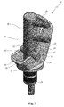
Fig. 3 shows a perspective view of a detail of the plant offigure 1 , relative to a device for supplying an electrolyte solution to a cell of a battery according to the present invention; -
Fig. 4 shows a side view of the supply device offigure 3 ; -
Fig. 5 shows an exploded view of the supply device offigure 3 ; -
Fig. 6 shows a section view of a first detail of the supply device offigure 3 , relative to a provided tubular body thereof, carried out along the line VI-VI ofFigure 4 ; -
Fig. 7 shows a perspective view of a second detail of the supply device offigure 3 , relative to a provided pressure element; -
Figs. 8A, 8B and 8C respectively show a perspective view, a side view and a section view carried out along the line ofFigure 8B of a third detail of the supply device offigure 3 , relative to a sealing element; -
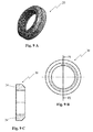
Figs. 9A, 9B and 9C respectively show a perspective view, a side view and a section view carried out along the line IX-IX ofFigure 9B of a fourth detail of the supply device offigure 3 , relative to an abutment element; -
Figs. 10A, 10B and 10C respectively show a perspective view, a side view and a section view, carried out along the line X-X ofFigure 10B , of a fifth detail of the supply device offigure 3 , relative to a filter. - With reference to the set of drawings,
reference number 1 indicates overall an embodiment of a plant for the electrochemical formation of batteries, object of the present invention. - In accordance with the enclosed figures, a plurality of
batteries 2, in particular of batteries for industrial vehicles such as truck batteries, is positioned above a bed or a pallet for facilitated transport. Eachbattery 2 comprises a rigid container in an entirely conventional manner, made of plastic material of box-like shape, which is closed on the upper part by acover 3 which bears, externally and projectingly fixed, a positive electrode and a negative electrode. Each of such electrodes is also extended within the container in order to be connected to the plates of its relative polarity. The electrodes are connected for the process of electrochemical formation to respective conduction bars of opposite polarity, in turn connected to an electrical energy source that feeds them with direct current, according to pre-established charge programs. - The
cover 3 of each of thebatteries 2 comprises one ormore openings 4, each of which in communication with the interior of a corresponding cell of thebattery 2, in order to allow the introduction of the electrolyte solution in the latter and its drawing from the latter. The batteries for vehicles, such as in particular the truck batteries, generally comprise six cells and thecovers 3 of their containers therefore comprise the same number ofopenings 4, as illustrated inFigure 2 . As in particular illustrated inFigure 2A , the walls that internally delimit each of theopenings 4 on thecovers 3 of thetruck batteries 2 are usually provided with athread 5, which has size and depth variable as a function of thebattery model 2. - The
plant 1 according to the invention comprises acircuit 6, in which an electrolyte solution circulates, which in accordance with the prior art can be obtained, in an entirely conventional manner, mainly with sulfuric acid (electrolyte) in aqueous solution. Thecircuit 6 is configured for reaching all thebatteries 2 that are subjected to the process of electrochemical formation of theplant 1, making an electrolyte solution circulate through them which is suitably cooled and controlled with regard to its electrolyte concentration. - The
circuit 6 for the circulation of the electrolyte solution comprises feeding means 7 for feeding the cells of thebatteries 2 with a first flow of electrolyte solution at a controlled piezometric pressure. - The
plant 1 according to the present invention also comprises, as illustrated inFigure 1 , return means 8 for drawing, under reduced pressure, the aforesaid first flow of electrolyte solution from thebatteries 2 so as to generate a continuous circulation of solution at their interior. - More in detail, the feeding means 7 comprise a
delivery tube 14 connected to at least onedistribution manifold 15 in order to convey the first flow of electrolyte solution into theelements 2 of the batteries. - In turn, the return means 8 comprise a
collection tube 16 connected to at least onesuction manifold 17, which is under reduced pressure in order to suck from theelements 2 the first flow of electrolyte solution, which has been introduced into theelements 2 from thedistribution manifold 15. - In order to allow the easy introduction and removal of the electrolyte solution into and from the cells, the
plant 1 further comprises a plurality ofdevices 9 for supplying the electrolyte solution to the cells of thebatteries 2. Each of thesupply devices 9 is susceptible to be removably and sealingly mounted on thecover 3 of one of thebatteries 2, at one of theopenings 4, and connected to the feeding means 7, in order to receive from the latter a flow of electrolyte solution and convey it into the corresponding cell, and to the return means 8, in order to extract the flow of electrolyte solution from the corresponding cell. - In particular, for the electrochemical forming of a truck battery, six
supply devices 9 will be sealingly mounted on thecover 3 of the aforesaid battery, one in each of the sixopenings 4 obtained on thecover 3 itself. - In accordance with the idea underlying the present invention, each of the
supply devices 9 is provided with atubular body 10, which has preferred extension along a longitudinal direction X and comprising anend portion 11 adapted to be at least partially removably inserted in one of theopenings 4 of thecover 3 of abattery 2. More in detail, thetubular body 10 advantageously comprises, in addition to theend portion 11, agrip portion 29, adapted to be handled by an operator in order to insert and remove theend portion 11 into and from theopenings 4 on thecovers 3 of thebatteries 2. According to the embodiment illustrated in the enclosed figures, theend portion 11 of thetubular body 10 is extended from thegrip portion 29, in a single body therewith. - Preferably, the
grip portion 29 and theend portion 11 of thetubular body 10 have a substantially cylindrical form, as illustrated in the enclosed figures, so as to be respectively easier to handle and easier to insert in acorresponding opening 4 of thecover 3 of abattery 2. In particular, theend portion 11 has a smaller transverse section that that of thegrip portion 29 and defines ashoulder 30 with the latter. - The
tubular body 10 also comprises, as illustrated inFigure 6 , at least oneinlet duct 12 connected to the feeding means 7, in order to receive from the latter the flow of electrolyte solution and convey it into the corresponding cell, and anoutlet duct 13 connected to the return means 8, for the extraction of the flow of electrolyte solution from the cell. - More in detail, the
inlet duct 12 and theoutlet duct 13 of eachsupply device 9 are connected to the circuit of distribution of the electrolyte solution before starting up theplant 1 as specified hereinbelow. - The
inlet duct 12 of thedevice 9 of eachelement 2 is connected by means of afirst connector 18 to thedistribution manifold 15 in order to feed, with the first flow of electrolyte solution, thecorresponding elements 2, while theoutlet duct 13 is connected with asecond connector 19 to thesuction manifold 17, in order to extract the first flow of electrolyte solution from theelements 2 themselves, i.e. that flow that entered into the containers of theelements 2 through theinlet duct 12. - Still in accordance with the idea underlying the present invention, each of the
supply devices 9 further comprises, mounted on theend portion 11 thereof, anabutment element 20, apressure element 21 and one ormore sealing elements 22, as well as alever 23 preferably mounted on itsgrip portion 29, as better described hereinbelow. - The
abutment element 20 is fixed to theend portion 11 of thetubular body 10, preferably at thefree end 31 of the latter opposite theshoulder 30, and has anannular abutment face 24, which is extended around theend portion 11, with at least one component thereof substantially perpendicular to the longitudinal direction X. In particular theannular abutment face 24 is substantially extended in radial direction around theend portion 11 of thetubular body 10. - Advantageously, at the
free end 31 thereof, theend portion 11 of thetubular body 10 is provided with a threadedterminal section 32 and theabutment element 20 is defined by a ring nut susceptible to be screwed on such threadedterminal section 32. - The
pressure element 21 is mounted on theend portion 11 of thetubular body 10 and has anannular pressure face 25, which faces theabutment face 24 of theabutment element 20 and is extended around theend portion 11, it too with at least one component thereof substantially perpendicular to the longitudinal direction X of preferred extension of thetubular body 10. More in detail, thepressure element 21 is circumferentially mounted on theend portion 11, in particular in abutment against theshoulder 30 at least in one position thereof, and itsannular pressure face 25 is radially extended around theend portion 11 of thetubular body 10. - Each of the elastically
deformable sealing elements 22 are perimetrically mounted on theend portion 11 of thetubular body 10, interposed between theannular abutment face 24 and theannular pressure face 25. - The
pressure element 21 is movable with respect to thetubular body 10 along the longitudinal direction X between a compression position, in which it is brought close to theabutment element 20 and causes the compression of the sealingelement 22 along the longitudinal direction X and its perimeter expansion via elastic deformation, and a rest position, illustrated inFigures 3 and4 , in which it is spaced from theabutment element 20 and, advantageously, is in abutment against theshoulder 30 of thetubular body 10. Thepressure element 21 is moved between the rest position and the compression position by means of thelever 23, which is constrained to thetubular body 10 and in particular is manually actuatable. - The sealing
element 22, elastically deformed due to the action of thepressure element 21 arranged in compression position, is susceptible to obtain a sealing between thetubular body 10 and thecover 3 of one of the batteries when theend portion 11 of thetubular body 10 is inserted in theopening 4 of thecover 3. - More in detail, the sealing
element 22 mounted on thetubular body 10 is extended for a section I of theend portion 11 of the latter along the longitudinal extension direction X, when thepressure element 21 is situated in the rest position. - In operation, when the
lever 23 is actuated for moving thepressure element 21 from the rest position to the compression position, the approaching of thepressure element 21 to theabutment element 20, i.e. its moving away from theshoulder 30, reduces the section of theend portion 11 occupied by the sealingelement 22, causing the compression of the latter and its elastic deformation. In particular, the sealingelement 22 is forced to be perimetrically expanded. When theend portion 11 of thesupply device 9 is inserted in anopening 4 of thecover 3 of abattery 2, the perimeter expansion of the sealingelement 22 ensures that the latter adheres to the walls that internally delimit theopening 4 itself, ensuring an optimal seal between thesupply device 9 and thecover 3. - The
supply device 9 for the plant according to the present invention is therefore adapted to be used for the electrochemical formation of different models of batteries and, in particular, different models of truck batteries such as, as previously specified, they can have different size and in particular different depth of thethread 5 obtained at theopening 4 on theircover 3. The sealingelement 22 arranged on thesupply device 9 is indeed able to obtain a seal on thecover 3, independent of the size and depth of the thread provided on the walls that internally delimit theopenings 4 of thecover 3. - In accordance with a preferred embodiment thereof illustrated in the enclosed figures, the
supply device 9 for plants according to the present invention comprises two sealingelements 22', 22" mounted on theend portion 11 of thetubular body 10 and further comprises aspacer element 26 mounted on theend portion 11 of thetubular body 10 interposed between the two sealingelements 22', 22" and movable with respect to thetubular body 10 along the longitudinal direction X. - Due to the fact that the
spacer element 26 interposed between the sealing elements is movable along the longitudinal direction X, the movement of thepressure element 21 from the rest position to the compression position involves the compression of both sealingelements 22', 22". - The presence of multiple sealing
elements 22 ensures greater versatility of thesupply device 9, in order to be used for the electrochemical formation ofbatteries 2 of different models. - Of course, as a function of the specific needs, i.e. in particular as a function of the depth of the
openings 4 on thecover 3 of thebatteries 2 that must be formed in theplant 1, eachsupply device 9 can also comprise a greater number of sealing elements, separated from each other by spacer elements. - In order to facilitate the perimeter expansion of the sealing
elements 22 when they are elastically deformed due to the action of thepressure element 21 arranged in the thrust position, aperimeter recess 28 is obtained, starting from theinternal surface 27 of contact with theend portion 11 of thetubular body 10 of each of the sealingelements 22;such perimeter recess 28 substantially defines a weakening line of the sealingelement 22 at which the sealingelement 22 can be more easily deformed. - The presence of
such perimeter recess 28 in each of the sealingelements 22 prevents the latter, when compressed via action of thepressure element 21, from being deformed in a different manner rather than being perimetrically expanded; for example, by overlapping with a flap portion thereof a portion of thepressure element 21, of theabutment element 20 or of thespacer element 26, in such case negatively affecting the correct operation of thedevice 9, i.e. in particular reducing its capacity to make a seal on thecover 3 of thebattery 2. - Advantageously, each of the sealing
elements 22 is made of a polymer and preferably elastomeric material, capable of resisting acidic substances, such as an EPDM rubber, since it can easily come into contact with the electrolyte solution made to circulate in the cell of thebattery 3. - In accordance with the preferred embodiment illustrated in the enclosed figures, the
lever 23 is rotatably engaged with thetubular body 10, and in particular with thegrip portion 29 of the latter, by means of one or more pins 33 (preferably two opposing pins) and is provided with anoperative portion 34, adapted to act on thepressure element 21 in order to retain it in the compression position, and with anon-operative portion 35, adapted to allow thepressure element 21 to remain in the rest position. Theoperative portion 34 and thenon-operative portion 35 are connected by acam portion 36 of thelever 23. Thelever 23 can be moved in rotation around thepins 33 between an operative position (not illustrated) and a non-operative position (illustrated inFigures 3 and4 ) by surmounting thecam portion 36. - In particular, in the operative position, the
operative portion 34 of thelever 23 is interposed between thepin 33 and thepressure element 21 and acts on the latter in order to maintain it in the compression position. In the non-operative position, thenon-operative portion 35 of thelever 23 is interposed between thepins 33 and thepressure element 21 and allows the latter to remain in the rest position. - Preferably, the
lever 23 comprises two facingtwin parts 37 connected byconnector portions 38, suchtwin parts 37 constrained to thetubular body 10 in opposite positions, each by means of a corresponding pin of thepins 33. Each of thetwin parts 37 comprises an operative wing and a non-operative wing. The operative wings of the twotwin parts 37 together define theoperative portion 34 of thelever 23 and the non-operative wings of the twotwin parts 37 together define thenon-operative portion 35 of thelever 23. - The
pressure element 21 is advantageously provided with aflange 39 on two opposite portions, on which the twotwin parts 37 of thelever 25 are adapted to operate. - In operation, in order to bring the sealing
elements 22 to be perimetrically expanded, thelever 23 is manually moved in rotation around thepins 33 from the non-operative position to the operative position, by surmounting thecam portion 36. During the rotation of thelever 23, thepressure element 21 is thrust by thecam portion 36 of the latter to move away from thepins 33 and from theshoulder 30 of thetubular body 10 and move closer to theabutment element 20, consequently causing the compression of the sealingelements 22 and their perimeter expansion. Thelever 23, once it has reached the operative position, with itsoperative portion 34 that maintains thepressure element 21 thrusted against the sealingelements 22, is retained in the aforesaid position by thecam portion 36 which prevents its return into the non-operative position. - The
lever 23 is advantageously provided with one ormore seats 40, each of which adapted to receive a corresponding pin of thepins 33 in order to be constrained to thetubular body 10. Eachseat 40 is open on the upper part by means of anopening 41 delimited by opposingengagement appendages 42 of thelever 23. Each of thepins 33 is snap-insertable in thecorresponding seat 40 of thelever 23 through theopening 41 via elastic deformation of theengagement appendages 42. - When the
pins 33 are inserted in the correspondingseats 40, theengagement appendages 42 prevent the same from exiting from theseats 40 due only to the action of the weight force that acts on thelever 23. Nevertheless, it will suffice to exert a traction force on thelever 23 to cause an elastic deformation of theengagement appendages 42 and release thelever 23 from thetubular body 10 in a simple and quick manner. - Therefore, the fact that the
seats 40 are open on the upper part allows constraining and releasing thelever 23 to and from thetubular body 10 in a quick and facilitated manner. - The
tubular body 10 preferably comprises afirst coupling duct 43, which is in direct hydraulic communication with theinlet duct 12 of thetubular body 10 and is susceptible to be connected to the feeding means 7 in order to receive the flow of electrolyte solution therefrom, and asecond coupling duct 44, which is in hydraulic communication with theoutlet duct 13 of thetubular body 10 and is susceptible to be connected to the return means 8 in order to transfer thereto the flow of electrolyte solution exiting from the cell. Thefirst coupling duct 43 and thesecond coupling duct 44 are extended along substantially parallel directions, Z' and Z", having at least one component orthogonal to the longitudinal direction X of preferred extension of thetubular body 10. Thelever 23 is constrained to thetubular body 10 in a manner so as to be movable in rotation on a plane substantially orthogonal to the components Y' and Y" of the directions Z and Z' orthogonal to the longitudinal direction X. - In such a manner, the presence of the first and second coupling duct on the
tubular body 10 do not prevent the rotation of thelever 23 nor do they interfere with the hand of the operator that moves thelever 23 in rotation. - The
supply device 9 preferably comprises ametering spout 45, which is traversed by theoutlet duct 13, and afilter 46 mounted on themetering spout 45, adapted to filter possible impurities that have been collected from the electrolyte solution flows within thecells 2 during charging. The electrolyte solution is sucked into theoutlet duct 13 through amouth 49 of theoutlet duct 13 provided for on themetering spout 45, which therefore defines the level of electrolyte solution contained in the corresponding cell. - In particular, the
filter 46 is susceptible to be inserted on themetering spout 45 and for such purpose comprises ahousing 47, adapted to receive themetering spout 45 with themouth 49 of theoutlet duct 13 placed in thehousing 47, and at least twomouths 48 for the passage of the electrolyte solution communicating with thehousing 47. Preferably, thefilter 46 comprises fourmouths 48 for the passage of the electrolyte solution. - The presence of the
filter 46 ensures a continuous suction of the electrolyte solution into theoutlet duct 13, even if an impurity present in the electrolyte solution is arranged in front of one of thepassage mouths 48, preventing the suction of electrolyte solution through it. - In addition, the
filter 46 facilitates the maintenance of thesupply device 9, since the impurities that come to be arranged in front of one of thepassage mouths 48 during the charging process can be easily identified and removed at the end of the process itself. - In addition, the
passage mouths 48 are advantageously sized in order to ensure a total inlet section of the electrolyte solution (determined by the sum of the sections of the passage mouths 48) greater than the outflow section (determined by the section of the outlet duct 13), such that the speed of the electrolyte solution entering through thepassage mouths 48 is reduced with respect to the speed that it would have without the presence of thefilter 46. Given the low speed of the electrolyte solution entering into thefilter 46, the probability that an impurity is sucked with force into one of thepassage mouths 48, obstructing it, is considerably reduced. - Advantageously, the
filter 46 is inserted under pressure on themetering spout 45. - Also forming an object of the present invention is a device for supplying an electrolyte solution to a cell of a battery for a plant for the electrochemical formation of batteries in particular of the above-described type; the same reference numbers are maintained hereinbelow.
- The
supply device 9, as specified above, is susceptible to be removably and sealingly mounted on thecover 3 of abattery 2 at a providedopening 4 of thecover 3 and to be connected to the feeding means 7 and to returnmeans 8 of theplant 1 for the electrochemical formation of batteries. Thesupply device 9 is adapted to receive from the feeding means 7 a flow of the electrolyte solution and to convey it into a corresponding cell of the battery, and it is adapted to transfer to the return means 8 the flow of electrolyte solution drawn from the cell. - As described above, the supply device comprises a
tubular body 10, having preferred extension along a longitudinal direction X and comprising anend portion 11 adapted to be at least partially removably inserted in anopening 4 of thecover 3 of abattery 2. Thetubular body 10 also comprises aninlet duct 12, susceptible to be connected to the feeding means 7 in order to receive from the latter the aforesaid electrolyte solution flow and to convey it into the corresponding cell, and anoutlet duct 13 connected to the return means 8 for the extraction of the electrolyte solution flow from the cell. - The
device 9 further comprises anabutment element 20, apressure element 21, one ormore sealing elements 22 and alever 23 mounted on itsend portion 11. - The
abutment element 20 is fixed to theend portion 11 of thetubular body 10 and has anannular abutment face 24, which is extended around theend portion 11 with at least one component thereof substantially perpendicular to the longitudinal direction X. - The
pressure element 21 is mounted on theend portion 11 of thetubular body 10 and has anannular pressure face 25, which faces theabutment face 24 of theabutment element 20 and is extended around theend portion 11 with at least one component thereof substantially perpendicular to the longitudinal direction X. - The elastically deformable sealing
element 22 is perimetrically mounted on theend portion 11 of thetubular body 10, interposed between theannular abutment face 24 and theannular pressure face 25. - The
pressure element 21 is movable with respect to thetubular body 10 along the longitudinal direction X between a compression position, in which it is brought close to theabutment element 20 and causes the compression of the sealingelement 22, or of the sealingelements 22, along the longitudinal direction X and its perimeter expansion via elastic deformation, and a rest position in which it is spaced from theabutment element 20. - The
lever 23 is constrained to thetubular body 10 and can be actuated to act on thepressure element 21 in order to move it between the rest position and the compression position. - The sealing
element 22, elastically deformed due to the action of thepressure element 21 arranged in the compression position, is susceptible to obtain a sealing between thetubular body 10 and thecover 3 of one of the batteries when theend portion 11 of thetubular body 10 is inserted in anopening 4 of thecover 3. - The finding thus conceived therefore attains the pre-established objects.
- Of course, in the practical attainment thereof, it can also assume forms and configurations that are different from that illustrated above, without departing from the present protective scope. In addition, all details can be substituted by technically equivalent elements and the size, shapes and materials employed can be of any type according to the needs.
Claims (11)
- Plant for the electrochemical formation of batteries, of the type each provided with a rigid container containing at least one cell and closed on the upper part by a cover (3) provided with at least one opening (4) in communication with said cell, said plant (1) comprising:- means (7) for feeding an electrolytic solution to battery cells (2);- return means (8) for extracting said electrolytic solution from said cells;- a plurality of devices (9) for supplying said electrolytic solution to the cells of said batteries (2), each device susceptible to being removably and sealingly mounted on the cover (3) of one of said batteries (2) at one of said openings (4) and connected to said feeding means (7), in order to receive an electrolytic solution flow from the latter and convey it into a corresponding cell, and to said return means (8) in order to extract said flow from said cell;
characterized in that each of said supply devices (9) is provided with:- a tubular body (10), having preferred extension along a longitudinal direction (X) and comprising an end portion (11) adapted to be at least partially removably inserted in an opening (4) of the cover (3) of one of said batteries (2), said tubular body (10) also comprising at least one inlet duct (12), connected to said feeding means (7) in order to receive said electrolytic solution flow from the latter and convey it into the corresponding cell, and an outlet duct (13) connected to said return means (8) for the extraction of said electrolytic solution flow from said cell;- an abutment element (20) fixed to the end portion (11) of said tubular body (10) and having an annular abutment face (24) being externally extended around said end portion (11);- a pressure element (21) mounted on the end portion (11) of said tubular body (10), and having an annular pressure face (25) facing the abutment face (24) of said abutment element (20) and being externally extended around said end portion (11);- at least one elastically deformable sealing element (22), which is perimetrically mounted on the end portion (11) of said tubular body (10), interposed between said annular abutment face (24) and said annular pressure face (25);
said pressure element (21) being movable with respect to said tubular body (10) along said longitudinal direction (X) between a compression position, in which it is brought close to said abutment element (20) and causes the compression of said at least one sealing element (22) along said longitudinal direction (X) and the perimeter expansion thereof via elastic deformation, and a rest position in which it is spaced from said abutment element (20);- a lever (23) mechanically constrained to said tubular body (10) and actuatable to act on said pressure element (21) in order to move it between said rest position and said compression position;said at least one sealing element (22) being elastically deformed due to the action of said pressure element (21) in said compression position and being susceptible to make a seal between said tubular body (10) and the cover (3) of one of said batteries (2) when the end portion (11) of said tubular body (10) is inserted in an opening (4) of said cover (3). - Plant for the electrochemical formation of batteries according to claim 1, characterized in that said at least one sealing element (22) is provided with an internal surface (27) of contact with the end portion (11) of said tubular body (10) and a perimeter recess (28) obtained starting from said internal surface (27) and adapted to facilitate the perimeter expansion of said at least one sealing element (22) when elastically deformed due to the action of said pressure element (21) arranged in said thrust position.
- Plant for the electrochemical formation of batteries according to any one of the preceding claims, characterized in that each of said supply devices (9) comprises at least two elastically deformable sealing elements (22) mounted on the end portion (11) of said tubular body (10) and also comprises at least one spacer element (26) mounted on the end portion (11) of said tubular body (10) interposed between said at least two sealing elements (22) and movable with respect to said tubular body (10) along said longitudinal direction (X).
- Plant for the electrochemical formation of batteries according to any one of the preceding claims, characterized in that said at least one sealing element (22) is made of a polymer material that is resistant to acidic substances.
- Plant for the electrochemical formation of batteries according to any one of the preceding claims, characterized in that said lever (23) is rotatably engaged to said tubular body (10) by means of at least one pin (33) and is provided with an operative portion (34), adapted to act on said pressure element (21) in order to retain it in said compression position, and a non-operative portion (35), adapted to allow said pressure element (21) to remain in said rest position, and with a cam portion (36) which separates said operative portion (34) and said non-operative portion (35) from each other, said lever (23) being movable in rotation around said at least one pin (33), going beyond said cam portion (36), between:- an operative position, in which said operative portion (34) is interposed between said pin (33) and said pressure element (21) and acts on the latter in order to maintain it in said compression position; and- a non-operative position, in which said non-operative portion (35) is interposed between said pin (33) and said pressure element (21) and allows the latter to remain in said rest position.
- Plant for the electrochemical formation of batteries according to claim 5, characterized in that said lever (23) is provided with at least one seat (40), which is adapted to receive said at least one pin (33) and on the upper part is open by means of an opening (41) delimited by opposing engagement appendages (42) of said lever (23), said at least one pin (33) being snap-insertable in the at least one seat (40) of said lever (23) through said opening (41) via elastic deformation of said engagement appendages (42).
- Plant for the electrochemical formation of batteries according to any one of the preceding claims, characterized in that said abutment element (20) is defined by a ring nut susceptible to being screwed to a threaded terminal section (32) of the end portion (11) of said tubular body (10).
- Plant for the electrochemical formation of batteries according to any one of the preceding claims, characterized in that said tubular body (10) comprises at least one first coupling duct (43), which is in hydraulic communication with said at least one inlet duct (12) and is susceptible to be connected to said feeding means (7) in order to receive said electrolytic solution flow from the latter, and at least one second coupling duct (44), which is in hydraulic communication with said outlet duct (13) and is susceptible to be connected to said return means (8) in order to transfer to the latter said electrolytic solution flow exiting from said cell, said first coupling duct (43) and said second coupling duct (44) being extended along substantially parallel directions (Z' and Z") having at least one component orthogonal to the preferred longitudinal extension direction (X) of said tubular body (10) and said lever (23) being constrained to said tubular body (10) in a manner such that it can be moved in rotation on a plane substantially orthogonal to the components (Y',Y") of the directions (Z', Z") orthogonal to said longitudinal direction (X).
- Plant for the electrochemical formation of batteries according to any one of the preceding claims, characterized in that said supply device (9) comprises a metering spout (45) and a filter (46) mounted on said metering spout (45).
- Plant for the electrochemical formation of batteries according to claim 9, characterized in that said filter (46) is susceptible to be inserted on said metering spout (45) and comprises a housing (47) for such purpose, adapted to receive said metering spout (45), and at least two inlet mouths (48) for said electrolytic solution communicating with said housing (47).
- Device for supplying an electrolytic solution to a cell of a battery for a plant for the electrochemical formation of batteries in accordance with any one of the preceding claims, said supply device (9) being susceptible to be removably and sealingly mounted on the cover (3) of a battery (2) at a provided opening (4) of said cover (3) and connected to feeding means (7) and to return means (8) of said plant (1) for the electrochemical formation, characterized in that it comprises:- a tubular body (10), having preferred extension along a longitudinal direction (X) and comprising one end portion (11) adapted to be at least partially removably inserted in said opening (4) of the cover (3) of one of said batteries (2), said tubular body (10) also comprising at least one inlet duct (12) susceptible to be connected to said feeding means (7) in order to receive an electrolytic solution flow from the latter and convey it into a corresponding cell of said battery (2), and an outlet duct (13) susceptible to be connected to said return means (8) for the extraction of said electrolytic solution flow from said cell;- an abutment element (20) fixed to the end portion (11) of said tubular body (10) and having an annular abutment face (24) being extended around said end portion (11) with at least one component thereof substantially perpendicular to said longitudinal direction (X);- a pressure element (21) mounted on the end portion (11) of said tubular body (10), and having an annular pressure face (25) facing the abutment face (24) of said abutment element (20) and being extended around said end portion (11) with at least one component thereof substantially perpendicular to said longitudinal direction (X);- at least one elastically deformable sealing element (22), which is perimetrically mounted on the end portion (11) of said tubular body (10), interposed between said annular abutment face (24) and said annular pressure face (25);
said pressure element (21) being movable with respect to said tubular body (10) along said longitudinal direction (X) between a compression position, in which it is brought close to said abutment element (20) and causes the compression of said at least one sealing element (22) along said longitudinal direction (X) and the perimeter expansion thereof via elastic deformation, and a rest position in which it is spaced from said abutment element (20);- a lever (23) constrained to said tubular body (10) and actuatable to act on said pressure element (21) in order to move it between said rest position and said compression position;
said at least one sealing element (22), elastically deformed due to the action of said pressure element (21) arranged in said compression position, being susceptible to make a seal between said tubular body (10) and the cover (3) of one of said batteries when the end portion (11) of said tubular body (10) is inserted in an opening (4) of said cover (3).
Applications Claiming Priority (1)
| Application Number | Priority Date | Filing Date | Title |
|---|---|---|---|
| IT000127A ITPD20130127A1 (en) | 2013-05-10 | 2013-05-10 | PLANT FOR ELECTROCHEMICAL TRAINING OF ACCUMULATORS AND ADDITIONAL DEVICE OF AN ELECTROLYTIC SOLUTION TO A CELL OF AN ACCUMULATOR FOR SUCH SYSTEM |
Publications (2)
| Publication Number | Publication Date |
|---|---|
| EP2802028A1 true EP2802028A1 (en) | 2014-11-12 |
| EP2802028B1 EP2802028B1 (en) | 2017-10-25 |
Family
ID=48703715
Family Applications (1)
| Application Number | Title | Priority Date | Filing Date |
|---|---|---|---|
| EP14167635.3A Active EP2802028B1 (en) | 2013-05-10 | 2014-05-09 | Plant for the electrochemical formation of batteries and device for supplying an electrolyte solution to a cell of a battery for said plant |
Country Status (2)
| Country | Link |
|---|---|
| EP (1) | EP2802028B1 (en) |
| IT (1) | ITPD20130127A1 (en) |
Citations (6)
| Publication number | Priority date | Publication date | Assignee | Title |
|---|---|---|---|---|
| GB376161A (en) * | 1931-11-25 | 1932-07-07 | William Edwin Reid | Improvements in and relating to filling devices for accumulator cells or the like |
| US5803138A (en) * | 1995-03-30 | 1998-09-08 | Elke Oschmann | Filling device for battery cells with a float-operated valve |
| DE102008029783B3 (en) * | 2008-06-25 | 2009-06-10 | Propper Gmbh & Co. Kg | Bottle e.g. champagne bottle, cap, has longitudinal and transverse bores provided in pivot for enabling pressure balance between inner side of bottle and surrounding, when tappet lever is pivotable from position to anther position |
| EP2133940A1 (en) * | 2008-06-12 | 2009-12-16 | TABA S.r.l. | Venting plug for stationary batteries, with blast-resistant protection and unlimited, automatic topping-up system, and topping-up assembly employing said plug |
| US20090314383A1 (en) * | 2008-06-24 | 2009-12-24 | Ianniello Massimiliano | Plant for electrochemical forming of lead-acid batteries |
| US20100205801A1 (en) * | 2008-12-23 | 2010-08-19 | Sovema S.P.A. | Plant for the electrochemical formation of lead-acid batteries |
-
2013
- 2013-05-10 IT IT000127A patent/ITPD20130127A1/en unknown
-
2014
- 2014-05-09 EP EP14167635.3A patent/EP2802028B1/en active Active
Patent Citations (6)
| Publication number | Priority date | Publication date | Assignee | Title |
|---|---|---|---|---|
| GB376161A (en) * | 1931-11-25 | 1932-07-07 | William Edwin Reid | Improvements in and relating to filling devices for accumulator cells or the like |
| US5803138A (en) * | 1995-03-30 | 1998-09-08 | Elke Oschmann | Filling device for battery cells with a float-operated valve |
| EP2133940A1 (en) * | 2008-06-12 | 2009-12-16 | TABA S.r.l. | Venting plug for stationary batteries, with blast-resistant protection and unlimited, automatic topping-up system, and topping-up assembly employing said plug |
| US20090314383A1 (en) * | 2008-06-24 | 2009-12-24 | Ianniello Massimiliano | Plant for electrochemical forming of lead-acid batteries |
| DE102008029783B3 (en) * | 2008-06-25 | 2009-06-10 | Propper Gmbh & Co. Kg | Bottle e.g. champagne bottle, cap, has longitudinal and transverse bores provided in pivot for enabling pressure balance between inner side of bottle and surrounding, when tappet lever is pivotable from position to anther position |
| US20100205801A1 (en) * | 2008-12-23 | 2010-08-19 | Sovema S.P.A. | Plant for the electrochemical formation of lead-acid batteries |
Also Published As
| Publication number | Publication date |
|---|---|
| ITPD20130127A1 (en) | 2014-11-11 |
| EP2802028B1 (en) | 2017-10-25 |
Similar Documents
| Publication | Publication Date | Title |
|---|---|---|
| EP2728650B1 (en) | Plant and process for the electrochemical formation of lead-acid batteries. | |
| EP2204866B1 (en) | Improved plant for the electrochemical formation of lead-acid batteries | |
| KR20210016762A (en) | Continuous recovery apparatus and method of valuable metals | |
| EP2802028B1 (en) | Plant for the electrochemical formation of batteries and device for supplying an electrolyte solution to a cell of a battery for said plant | |
| EP4020663B1 (en) | Solution discharges of cells and modules for battery recycling | |
| DE1930000A1 (en) | Electric storage battery | |
| CN208570703U (en) | A kind of cell jar | |
| WO2013143730A1 (en) | Temperature-control device, electrical system, method for reducing the risk of a short circuit on an electrical component, and motor vehicle | |
| CN209704136U (en) | A kind of unmanned plane hangar | |
| CN203085702U (en) | Lithium ion battery | |
| DE102009054016A1 (en) | Rejuvenating a pouch type lithium ion battery involves introducing solvent into manifold and pouch to treat respective electrode assembly, removing solvent, introducing electrolyte into manifold and pouch, and sealing the pouch | |
| CN208732132U (en) | A kind of opening connecting device for automatic loading/unloading | |
| EP2489090A1 (en) | Container arrangement for a fuel cell system, and method for introducing an ion exchange module in a coolant container | |
| DE202016000151U1 (en) | Battery replacement robot for electric cars with modularly scalable replaceable battery packs | |
| CN218334257U (en) | Continuous electrolyte adding device for storage battery | |
| CN204885279U (en) | From area filling electrolyte device battery | |
| CN204596911U (en) | Liquid-enriched and seal type formula tubular type maintenance-free lead accumulator | |
| CN215600476U (en) | Battery box with novel locking structure | |
| CN216054923U (en) | Quick-release structure for lead-acid storage battery of forklift | |
| CN205264800U (en) | Polar plate device of moisturizing | |
| CN220796943U (en) | Lithium battery box | |
| CN220949430U (en) | Temporary storage box for spinning solution for polypropylene spinning | |
| CN203026560U (en) | Storage battery container capable of facilitating plate group assembly | |
| CN103094622A (en) | Lithium ion battery | |
| CN203521542U (en) | Heat sealing device for aluminum foil of storage battery |
Legal Events
| Date | Code | Title | Description |
|---|---|---|---|
| PUAI | Public reference made under article 153(3) epc to a published international application that has entered the european phase |
Free format text: ORIGINAL CODE: 0009012 |
|
| 17P | Request for examination filed |
Effective date: 20140509 |
|
| AK | Designated contracting states |
Kind code of ref document: A1 Designated state(s): AL AT BE BG CH CY CZ DE DK EE ES FI FR GB GR HR HU IE IS IT LI LT LU LV MC MK MT NL NO PL PT RO RS SE SI SK SM TR |
|
| AX | Request for extension of the european patent |
Extension state: BA ME |
|
| R17P | Request for examination filed (corrected) |
Effective date: 20150512 |
|
| RBV | Designated contracting states (corrected) |
Designated state(s): AL AT BE BG CH CY CZ DE DK EE ES FI FR GB GR HR HU IE IS IT LI LT LU LV MC MK MT NL NO PL PT RO RS SE SI SK SM TR |
|
| GRAP | Despatch of communication of intention to grant a patent |
Free format text: ORIGINAL CODE: EPIDOSNIGR1 |
|
| RIC1 | Information provided on ipc code assigned before grant |
Ipc: H01M 10/12 20060101ALI20170330BHEP Ipc: H01M 2/36 20060101AFI20170330BHEP |
|
| INTG | Intention to grant announced |
Effective date: 20170412 |
|
| GRAS | Grant fee paid |
Free format text: ORIGINAL CODE: EPIDOSNIGR3 |
|
| GRAA | (expected) grant |
Free format text: ORIGINAL CODE: 0009210 |
|
| AK | Designated contracting states |
Kind code of ref document: B1 Designated state(s): AL AT BE BG CH CY CZ DE DK EE ES FI FR GB GR HR HU IE IS IT LI LT LU LV MC MK MT NL NO PL PT RO RS SE SI SK SM TR |
|
| RAP1 | Party data changed (applicant data changed or rights of an application transferred) |
Owner name: SOVEMA GROUP S.P.A. |
|
| REG | Reference to a national code |
Ref country code: GB Ref legal event code: FG4D |
|
| REG | Reference to a national code |
Ref country code: CH Ref legal event code: EP |
|
| REG | Reference to a national code |
Ref country code: AT Ref legal event code: REF Ref document number: 940696 Country of ref document: AT Kind code of ref document: T Effective date: 20171115 |
|
| REG | Reference to a national code |
Ref country code: IE Ref legal event code: FG4D |
|
| REG | Reference to a national code |
Ref country code: DE Ref legal event code: R096 Ref document number: 602014016176 Country of ref document: DE |
|
| REG | Reference to a national code |
Ref country code: NL Ref legal event code: MP Effective date: 20171025 |
|
| REG | Reference to a national code |
Ref country code: LT Ref legal event code: MG4D |
|
| REG | Reference to a national code |
Ref country code: AT Ref legal event code: MK05 Ref document number: 940696 Country of ref document: AT Kind code of ref document: T Effective date: 20171025 |
|
| PG25 | Lapsed in a contracting state [announced via postgrant information from national office to epo] |
Ref country code: NL Free format text: LAPSE BECAUSE OF FAILURE TO SUBMIT A TRANSLATION OF THE DESCRIPTION OR TO PAY THE FEE WITHIN THE PRESCRIBED TIME-LIMIT Effective date: 20171025 |
|
| PG25 | Lapsed in a contracting state [announced via postgrant information from national office to epo] |
Ref country code: LT Free format text: LAPSE BECAUSE OF FAILURE TO SUBMIT A TRANSLATION OF THE DESCRIPTION OR TO PAY THE FEE WITHIN THE PRESCRIBED TIME-LIMIT Effective date: 20171025 Ref country code: FI Free format text: LAPSE BECAUSE OF FAILURE TO SUBMIT A TRANSLATION OF THE DESCRIPTION OR TO PAY THE FEE WITHIN THE PRESCRIBED TIME-LIMIT Effective date: 20171025 Ref country code: SE Free format text: LAPSE BECAUSE OF FAILURE TO SUBMIT A TRANSLATION OF THE DESCRIPTION OR TO PAY THE FEE WITHIN THE PRESCRIBED TIME-LIMIT Effective date: 20171025 Ref country code: NO Free format text: LAPSE BECAUSE OF FAILURE TO SUBMIT A TRANSLATION OF THE DESCRIPTION OR TO PAY THE FEE WITHIN THE PRESCRIBED TIME-LIMIT Effective date: 20180125 Ref country code: ES Free format text: LAPSE BECAUSE OF FAILURE TO SUBMIT A TRANSLATION OF THE DESCRIPTION OR TO PAY THE FEE WITHIN THE PRESCRIBED TIME-LIMIT Effective date: 20171025 |
|
| PG25 | Lapsed in a contracting state [announced via postgrant information from national office to epo] |
Ref country code: RS Free format text: LAPSE BECAUSE OF FAILURE TO SUBMIT A TRANSLATION OF THE DESCRIPTION OR TO PAY THE FEE WITHIN THE PRESCRIBED TIME-LIMIT Effective date: 20171025 Ref country code: GR Free format text: LAPSE BECAUSE OF FAILURE TO SUBMIT A TRANSLATION OF THE DESCRIPTION OR TO PAY THE FEE WITHIN THE PRESCRIBED TIME-LIMIT Effective date: 20180126 Ref country code: LV Free format text: LAPSE BECAUSE OF FAILURE TO SUBMIT A TRANSLATION OF THE DESCRIPTION OR TO PAY THE FEE WITHIN THE PRESCRIBED TIME-LIMIT Effective date: 20171025 Ref country code: IS Free format text: LAPSE BECAUSE OF FAILURE TO SUBMIT A TRANSLATION OF THE DESCRIPTION OR TO PAY THE FEE WITHIN THE PRESCRIBED TIME-LIMIT Effective date: 20180225 Ref country code: HR Free format text: LAPSE BECAUSE OF FAILURE TO SUBMIT A TRANSLATION OF THE DESCRIPTION OR TO PAY THE FEE WITHIN THE PRESCRIBED TIME-LIMIT Effective date: 20171025 Ref country code: BG Free format text: LAPSE BECAUSE OF FAILURE TO SUBMIT A TRANSLATION OF THE DESCRIPTION OR TO PAY THE FEE WITHIN THE PRESCRIBED TIME-LIMIT Effective date: 20180125 Ref country code: AT Free format text: LAPSE BECAUSE OF FAILURE TO SUBMIT A TRANSLATION OF THE DESCRIPTION OR TO PAY THE FEE WITHIN THE PRESCRIBED TIME-LIMIT Effective date: 20171025 |
|
| REG | Reference to a national code |
Ref country code: DE Ref legal event code: R097 Ref document number: 602014016176 Country of ref document: DE |
|
| PG25 | Lapsed in a contracting state [announced via postgrant information from national office to epo] |
Ref country code: EE Free format text: LAPSE BECAUSE OF FAILURE TO SUBMIT A TRANSLATION OF THE DESCRIPTION OR TO PAY THE FEE WITHIN THE PRESCRIBED TIME-LIMIT Effective date: 20171025 Ref country code: DK Free format text: LAPSE BECAUSE OF FAILURE TO SUBMIT A TRANSLATION OF THE DESCRIPTION OR TO PAY THE FEE WITHIN THE PRESCRIBED TIME-LIMIT Effective date: 20171025 Ref country code: SK Free format text: LAPSE BECAUSE OF FAILURE TO SUBMIT A TRANSLATION OF THE DESCRIPTION OR TO PAY THE FEE WITHIN THE PRESCRIBED TIME-LIMIT Effective date: 20171025 Ref country code: CY Free format text: LAPSE BECAUSE OF FAILURE TO SUBMIT A TRANSLATION OF THE DESCRIPTION OR TO PAY THE FEE WITHIN THE PRESCRIBED TIME-LIMIT Effective date: 20171025 Ref country code: CZ Free format text: LAPSE BECAUSE OF FAILURE TO SUBMIT A TRANSLATION OF THE DESCRIPTION OR TO PAY THE FEE WITHIN THE PRESCRIBED TIME-LIMIT Effective date: 20171025 |
|
| PG25 | Lapsed in a contracting state [announced via postgrant information from national office to epo] |
Ref country code: SM Free format text: LAPSE BECAUSE OF FAILURE TO SUBMIT A TRANSLATION OF THE DESCRIPTION OR TO PAY THE FEE WITHIN THE PRESCRIBED TIME-LIMIT Effective date: 20171025 Ref country code: PL Free format text: LAPSE BECAUSE OF FAILURE TO SUBMIT A TRANSLATION OF THE DESCRIPTION OR TO PAY THE FEE WITHIN THE PRESCRIBED TIME-LIMIT Effective date: 20171025 Ref country code: RO Free format text: LAPSE BECAUSE OF FAILURE TO SUBMIT A TRANSLATION OF THE DESCRIPTION OR TO PAY THE FEE WITHIN THE PRESCRIBED TIME-LIMIT Effective date: 20171025 |
|
| PLBE | No opposition filed within time limit |
Free format text: ORIGINAL CODE: 0009261 |
|
| STAA | Information on the status of an ep patent application or granted ep patent |
Free format text: STATUS: NO OPPOSITION FILED WITHIN TIME LIMIT |
|
| 26N | No opposition filed |
Effective date: 20180726 |
|
| PG25 | Lapsed in a contracting state [announced via postgrant information from national office to epo] |
Ref country code: SI Free format text: LAPSE BECAUSE OF FAILURE TO SUBMIT A TRANSLATION OF THE DESCRIPTION OR TO PAY THE FEE WITHIN THE PRESCRIBED TIME-LIMIT Effective date: 20171025 |
|
| REG | Reference to a national code |
Ref country code: CH Ref legal event code: PL |
|
| GBPC | Gb: european patent ceased through non-payment of renewal fee |
Effective date: 20180509 |
|
| REG | Reference to a national code |
Ref country code: BE Ref legal event code: MM Effective date: 20180531 |
|
| PG25 | Lapsed in a contracting state [announced via postgrant information from national office to epo] |
Ref country code: MC Free format text: LAPSE BECAUSE OF FAILURE TO SUBMIT A TRANSLATION OF THE DESCRIPTION OR TO PAY THE FEE WITHIN THE PRESCRIBED TIME-LIMIT Effective date: 20171025 |
|
| REG | Reference to a national code |
Ref country code: IE Ref legal event code: MM4A |
|
| PG25 | Lapsed in a contracting state [announced via postgrant information from national office to epo] |
Ref country code: CH Free format text: LAPSE BECAUSE OF NON-PAYMENT OF DUE FEES Effective date: 20180531 Ref country code: LI Free format text: LAPSE BECAUSE OF NON-PAYMENT OF DUE FEES Effective date: 20180531 |
|
| PG25 | Lapsed in a contracting state [announced via postgrant information from national office to epo] |
Ref country code: LU Free format text: LAPSE BECAUSE OF NON-PAYMENT OF DUE FEES Effective date: 20180509 |
|
| PG25 | Lapsed in a contracting state [announced via postgrant information from national office to epo] |
Ref country code: GB Free format text: LAPSE BECAUSE OF NON-PAYMENT OF DUE FEES Effective date: 20180509 Ref country code: IE Free format text: LAPSE BECAUSE OF NON-PAYMENT OF DUE FEES Effective date: 20180509 Ref country code: FR Free format text: LAPSE BECAUSE OF NON-PAYMENT OF DUE FEES Effective date: 20180531 |
|
| PG25 | Lapsed in a contracting state [announced via postgrant information from national office to epo] |
Ref country code: BE Free format text: LAPSE BECAUSE OF NON-PAYMENT OF DUE FEES Effective date: 20180531 |
|
| PG25 | Lapsed in a contracting state [announced via postgrant information from national office to epo] |
Ref country code: MT Free format text: LAPSE BECAUSE OF NON-PAYMENT OF DUE FEES Effective date: 20180509 |
|
| PG25 | Lapsed in a contracting state [announced via postgrant information from national office to epo] |
Ref country code: TR Free format text: LAPSE BECAUSE OF FAILURE TO SUBMIT A TRANSLATION OF THE DESCRIPTION OR TO PAY THE FEE WITHIN THE PRESCRIBED TIME-LIMIT Effective date: 20171025 |
|
| PG25 | Lapsed in a contracting state [announced via postgrant information from national office to epo] |
Ref country code: HU Free format text: LAPSE BECAUSE OF FAILURE TO SUBMIT A TRANSLATION OF THE DESCRIPTION OR TO PAY THE FEE WITHIN THE PRESCRIBED TIME-LIMIT; INVALID AB INITIO Effective date: 20140509 Ref country code: PT Free format text: LAPSE BECAUSE OF FAILURE TO SUBMIT A TRANSLATION OF THE DESCRIPTION OR TO PAY THE FEE WITHIN THE PRESCRIBED TIME-LIMIT Effective date: 20171025 |
|
| PG25 | Lapsed in a contracting state [announced via postgrant information from national office to epo] |
Ref country code: MK Free format text: LAPSE BECAUSE OF NON-PAYMENT OF DUE FEES Effective date: 20171025 |
|
| PG25 | Lapsed in a contracting state [announced via postgrant information from national office to epo] |
Ref country code: AL Free format text: LAPSE BECAUSE OF FAILURE TO SUBMIT A TRANSLATION OF THE DESCRIPTION OR TO PAY THE FEE WITHIN THE PRESCRIBED TIME-LIMIT Effective date: 20171025 |
|
| REG | Reference to a national code |
Ref country code: DE Ref legal event code: R079 Ref document number: 602014016176 Country of ref document: DE Free format text: PREVIOUS MAIN CLASS: H01M0002360000 Ipc: H01M0050600000 |
|
| P01 | Opt-out of the competence of the unified patent court (upc) registered |
Effective date: 20230306 |
|
| PGFP | Annual fee paid to national office [announced via postgrant information from national office to epo] |
Ref country code: DE Payment date: 20250521 Year of fee payment: 12 |
|
| PGFP | Annual fee paid to national office [announced via postgrant information from national office to epo] |
Ref country code: IT Payment date: 20250528 Year of fee payment: 12 |