EP2801767A1 - Method for manufacturing a solar absorber body, a solar absorber body and a concentrating solar power system comprising said solar absorber body. - Google Patents
Method for manufacturing a solar absorber body, a solar absorber body and a concentrating solar power system comprising said solar absorber body. Download PDFInfo
- Publication number
- EP2801767A1 EP2801767A1 EP13354015.3A EP13354015A EP2801767A1 EP 2801767 A1 EP2801767 A1 EP 2801767A1 EP 13354015 A EP13354015 A EP 13354015A EP 2801767 A1 EP2801767 A1 EP 2801767A1
- Authority
- EP
- European Patent Office
- Prior art keywords
- barrier layer
- diffusion barrier
- solar
- layer
- absorber body
- Prior art date
- Legal status (The legal status is an assumption and is not a legal conclusion. Google has not performed a legal analysis and makes no representation as to the accuracy of the status listed.)
- Withdrawn
Links
- 239000006096 absorbing agent Substances 0.000 title claims abstract description 57
- 238000000034 method Methods 0.000 title claims abstract description 43
- 238000004519 manufacturing process Methods 0.000 title claims abstract description 11
- 230000004888 barrier function Effects 0.000 claims abstract description 83
- 238000009792 diffusion process Methods 0.000 claims abstract description 75
- 239000011819 refractory material Substances 0.000 claims abstract description 16
- 238000007751 thermal spraying Methods 0.000 claims abstract description 6
- 238000010521 absorption reaction Methods 0.000 claims description 34
- 239000000463 material Substances 0.000 claims description 34
- QDOXWKRWXJOMAK-UHFFFAOYSA-N dichromium trioxide Chemical compound O=[Cr]O[Cr]=O QDOXWKRWXJOMAK-UHFFFAOYSA-N 0.000 claims description 18
- 238000005498 polishing Methods 0.000 claims description 17
- 229910000831 Steel Inorganic materials 0.000 claims description 16
- 239000010959 steel Substances 0.000 claims description 16
- PNEYBMLMFCGWSK-UHFFFAOYSA-N aluminium oxide Inorganic materials [O-2].[O-2].[O-2].[Al+3].[Al+3] PNEYBMLMFCGWSK-UHFFFAOYSA-N 0.000 claims description 15
- 238000000151 deposition Methods 0.000 claims description 15
- 230000003667 anti-reflective effect Effects 0.000 claims description 13
- 229910000851 Alloy steel Inorganic materials 0.000 claims description 12
- 239000011651 chromium Substances 0.000 claims description 11
- 230000008569 process Effects 0.000 claims description 11
- VYZAMTAEIAYCRO-UHFFFAOYSA-N Chromium Chemical compound [Cr] VYZAMTAEIAYCRO-UHFFFAOYSA-N 0.000 claims description 10
- 229910007948 ZrB2 Inorganic materials 0.000 claims description 10
- VWZIXVXBCBBRGP-UHFFFAOYSA-N boron;zirconium Chemical compound B#[Zr]#B VWZIXVXBCBBRGP-UHFFFAOYSA-N 0.000 claims description 10
- 229910052804 chromium Inorganic materials 0.000 claims description 10
- 229910052593 corundum Inorganic materials 0.000 claims description 9
- 239000000203 mixture Substances 0.000 claims description 8
- 238000007669 thermal treatment Methods 0.000 claims description 8
- 229910001845 yogo sapphire Inorganic materials 0.000 claims description 8
- ZOKXTWBITQBERF-UHFFFAOYSA-N Molybdenum Chemical compound [Mo] ZOKXTWBITQBERF-UHFFFAOYSA-N 0.000 claims description 7
- 238000000227 grinding Methods 0.000 claims description 7
- 229910052750 molybdenum Inorganic materials 0.000 claims description 7
- 239000011733 molybdenum Substances 0.000 claims description 7
- 238000003754 machining Methods 0.000 claims description 6
- WFKWXMTUELFFGS-UHFFFAOYSA-N tungsten Chemical compound [W] WFKWXMTUELFFGS-UHFFFAOYSA-N 0.000 claims description 5
- 229910052721 tungsten Inorganic materials 0.000 claims description 5
- 239000010937 tungsten Substances 0.000 claims description 5
- 238000012546 transfer Methods 0.000 claims description 4
- WAIPAZQMEIHHTJ-UHFFFAOYSA-N [Cr].[Co] Chemical class [Cr].[Co] WAIPAZQMEIHHTJ-UHFFFAOYSA-N 0.000 claims description 3
- 238000007750 plasma spraying Methods 0.000 claims description 3
- 238000007749 high velocity oxygen fuel spraying Methods 0.000 claims description 2
- 229910000623 nickel–chromium alloy Inorganic materials 0.000 claims 2
- 239000013529 heat transfer fluid Substances 0.000 abstract description 8
- 239000000758 substrate Substances 0.000 description 41
- 238000000576 coating method Methods 0.000 description 22
- 239000011248 coating agent Substances 0.000 description 16
- VYPSYNLAJGMNEJ-UHFFFAOYSA-N Silicium dioxide Chemical compound O=[Si]=O VYPSYNLAJGMNEJ-UHFFFAOYSA-N 0.000 description 11
- 229910045601 alloy Inorganic materials 0.000 description 11
- 239000000956 alloy Substances 0.000 description 11
- PXHVJJICTQNCMI-UHFFFAOYSA-N Nickel Chemical compound [Ni] PXHVJJICTQNCMI-UHFFFAOYSA-N 0.000 description 10
- 239000003570 air Substances 0.000 description 8
- 230000001590 oxidative effect Effects 0.000 description 8
- 229910001220 stainless steel Inorganic materials 0.000 description 8
- 230000003287 optical effect Effects 0.000 description 7
- 230000003647 oxidation Effects 0.000 description 7
- 238000007254 oxidation reaction Methods 0.000 description 7
- XEEYBQQBJWHFJM-UHFFFAOYSA-N Iron Chemical compound [Fe] XEEYBQQBJWHFJM-UHFFFAOYSA-N 0.000 description 6
- HBMJWWWQQXIZIP-UHFFFAOYSA-N silicon carbide Chemical compound [Si+]#[C-] HBMJWWWQQXIZIP-UHFFFAOYSA-N 0.000 description 6
- 229910010271 silicon carbide Inorganic materials 0.000 description 6
- 238000005275 alloying Methods 0.000 description 5
- 230000008021 deposition Effects 0.000 description 5
- 229910052751 metal Inorganic materials 0.000 description 5
- 239000002184 metal Substances 0.000 description 5
- 230000005855 radiation Effects 0.000 description 5
- 239000000377 silicon dioxide Substances 0.000 description 5
- 239000000243 solution Substances 0.000 description 5
- 239000010935 stainless steel Substances 0.000 description 5
- CPLXHLVBOLITMK-UHFFFAOYSA-N Magnesium oxide Chemical compound [Mg]=O CPLXHLVBOLITMK-UHFFFAOYSA-N 0.000 description 4
- QVGXLLKOCUKJST-UHFFFAOYSA-N atomic oxygen Chemical compound [O] QVGXLLKOCUKJST-UHFFFAOYSA-N 0.000 description 4
- 239000011195 cermet Substances 0.000 description 4
- 229910052681 coesite Inorganic materials 0.000 description 4
- 229910052906 cristobalite Inorganic materials 0.000 description 4
- 230000007423 decrease Effects 0.000 description 4
- 229910052759 nickel Inorganic materials 0.000 description 4
- 229910052760 oxygen Inorganic materials 0.000 description 4
- 239000001301 oxygen Substances 0.000 description 4
- 238000005240 physical vapour deposition Methods 0.000 description 4
- BASFCYQUMIYNBI-UHFFFAOYSA-N platinum Chemical compound [Pt] BASFCYQUMIYNBI-UHFFFAOYSA-N 0.000 description 4
- 239000003870 refractory metal Substances 0.000 description 4
- 230000003595 spectral effect Effects 0.000 description 4
- 229910052682 stishovite Inorganic materials 0.000 description 4
- 239000000126 substance Substances 0.000 description 4
- 229910052905 tridymite Inorganic materials 0.000 description 4
- 229910018487 Ni—Cr Inorganic materials 0.000 description 3
- XUIMIQQOPSSXEZ-UHFFFAOYSA-N Silicon Chemical compound [Si] XUIMIQQOPSSXEZ-UHFFFAOYSA-N 0.000 description 3
- HEMHJVSKTPXQMS-UHFFFAOYSA-M Sodium hydroxide Chemical compound [OH-].[Na+] HEMHJVSKTPXQMS-UHFFFAOYSA-M 0.000 description 3
- 239000002585 base Substances 0.000 description 3
- 239000000919 ceramic Substances 0.000 description 3
- VNNRSPGTAMTISX-UHFFFAOYSA-N chromium nickel Chemical compound [Cr].[Ni] VNNRSPGTAMTISX-UHFFFAOYSA-N 0.000 description 3
- 238000009713 electroplating Methods 0.000 description 3
- 239000012530 fluid Substances 0.000 description 3
- 230000007774 longterm Effects 0.000 description 3
- 235000012245 magnesium oxide Nutrition 0.000 description 3
- 239000003921 oil Substances 0.000 description 3
- 238000002161 passivation Methods 0.000 description 3
- 238000012545 processing Methods 0.000 description 3
- 229910052710 silicon Inorganic materials 0.000 description 3
- 239000010703 silicon Substances 0.000 description 3
- XLYOFNOQVPJJNP-UHFFFAOYSA-N water Substances O XLYOFNOQVPJJNP-UHFFFAOYSA-N 0.000 description 3
- 229910052582 BN Inorganic materials 0.000 description 2
- PZNSFCLAULLKQX-UHFFFAOYSA-N Boron nitride Chemical compound N#B PZNSFCLAULLKQX-UHFFFAOYSA-N 0.000 description 2
- VEXZGXHMUGYJMC-UHFFFAOYSA-N Hydrochloric acid Chemical compound Cl VEXZGXHMUGYJMC-UHFFFAOYSA-N 0.000 description 2
- RTAQQCXQSZGOHL-UHFFFAOYSA-N Titanium Chemical compound [Ti] RTAQQCXQSZGOHL-UHFFFAOYSA-N 0.000 description 2
- QCWXUUIWCKQGHC-UHFFFAOYSA-N Zirconium Chemical compound [Zr] QCWXUUIWCKQGHC-UHFFFAOYSA-N 0.000 description 2
- 239000003082 abrasive agent Substances 0.000 description 2
- 238000007792 addition Methods 0.000 description 2
- 238000005229 chemical vapour deposition Methods 0.000 description 2
- 239000000788 chromium alloy Substances 0.000 description 2
- 238000005260 corrosion Methods 0.000 description 2
- 230000007797 corrosion Effects 0.000 description 2
- 230000005611 electricity Effects 0.000 description 2
- 239000003792 electrolyte Substances 0.000 description 2
- 150000002500 ions Chemical class 0.000 description 2
- 229910052742 iron Inorganic materials 0.000 description 2
- 239000000314 lubricant Substances 0.000 description 2
- 239000000395 magnesium oxide Substances 0.000 description 2
- 150000002739 metals Chemical class 0.000 description 2
- -1 metals compounds Chemical class 0.000 description 2
- 229910003465 moissanite Inorganic materials 0.000 description 2
- 229910052697 platinum Inorganic materials 0.000 description 2
- KWYUFKZDYYNOTN-UHFFFAOYSA-M potassium hydroxide Inorganic materials [OH-].[K+] KWYUFKZDYYNOTN-UHFFFAOYSA-M 0.000 description 2
- 239000000843 powder Substances 0.000 description 2
- VWDWKYIASSYTQR-UHFFFAOYSA-N sodium nitrate Chemical compound [Na+].[O-][N+]([O-])=O VWDWKYIASSYTQR-UHFFFAOYSA-N 0.000 description 2
- 239000007921 spray Substances 0.000 description 2
- 230000003746 surface roughness Effects 0.000 description 2
- 238000005382 thermal cycling Methods 0.000 description 2
- 229910052719 titanium Inorganic materials 0.000 description 2
- 239000010936 titanium Substances 0.000 description 2
- 229910052726 zirconium Inorganic materials 0.000 description 2
- ZOXJGFHDIHLPTG-UHFFFAOYSA-N Boron Chemical compound [B] ZOXJGFHDIHLPTG-UHFFFAOYSA-N 0.000 description 1
- OKTJSMMVPCPJKN-UHFFFAOYSA-N Carbon Chemical compound [C] OKTJSMMVPCPJKN-UHFFFAOYSA-N 0.000 description 1
- 229910000640 Fe alloy Inorganic materials 0.000 description 1
- CWYNVVGOOAEACU-UHFFFAOYSA-N Fe2+ Chemical compound [Fe+2] CWYNVVGOOAEACU-UHFFFAOYSA-N 0.000 description 1
- PWHULOQIROXLJO-UHFFFAOYSA-N Manganese Chemical compound [Mn] PWHULOQIROXLJO-UHFFFAOYSA-N 0.000 description 1
- 229910000990 Ni alloy Inorganic materials 0.000 description 1
- GRYLNZFGIOXLOG-UHFFFAOYSA-N Nitric acid Chemical compound O[N+]([O-])=O GRYLNZFGIOXLOG-UHFFFAOYSA-N 0.000 description 1
- ZLMJMSJWJFRBEC-UHFFFAOYSA-N Potassium Chemical compound [K] ZLMJMSJWJFRBEC-UHFFFAOYSA-N 0.000 description 1
- KJTLSVCANCCWHF-UHFFFAOYSA-N Ruthenium Chemical compound [Ru] KJTLSVCANCCWHF-UHFFFAOYSA-N 0.000 description 1
- 229910052581 Si3N4 Inorganic materials 0.000 description 1
- BQCADISMDOOEFD-UHFFFAOYSA-N Silver Chemical compound [Ag] BQCADISMDOOEFD-UHFFFAOYSA-N 0.000 description 1
- QAOWNCQODCNURD-UHFFFAOYSA-N Sulfuric acid Chemical compound OS(O)(=O)=O QAOWNCQODCNURD-UHFFFAOYSA-N 0.000 description 1
- 229910001069 Ti alloy Inorganic materials 0.000 description 1
- 238000005299 abrasion Methods 0.000 description 1
- 239000002253 acid Substances 0.000 description 1
- 229910052782 aluminium Inorganic materials 0.000 description 1
- 239000004411 aluminium Substances 0.000 description 1
- XAGFODPZIPBFFR-UHFFFAOYSA-N aluminium Chemical compound [Al] XAGFODPZIPBFFR-UHFFFAOYSA-N 0.000 description 1
- 239000003637 basic solution Substances 0.000 description 1
- 238000005422 blasting Methods 0.000 description 1
- 229910052796 boron Inorganic materials 0.000 description 1
- 239000006227 byproduct Substances 0.000 description 1
- 229910052799 carbon Inorganic materials 0.000 description 1
- 238000006243 chemical reaction Methods 0.000 description 1
- 239000002131 composite material Substances 0.000 description 1
- 150000001875 compounds Chemical class 0.000 description 1
- 239000012141 concentrate Substances 0.000 description 1
- 239000000356 contaminant Substances 0.000 description 1
- 238000011109 contamination Methods 0.000 description 1
- 239000010431 corundum Substances 0.000 description 1
- 238000005336 cracking Methods 0.000 description 1
- 238000005520 cutting process Methods 0.000 description 1
- 230000001351 cycling effect Effects 0.000 description 1
- 238000001035 drying Methods 0.000 description 1
- 230000000694 effects Effects 0.000 description 1
- 239000008151 electrolyte solution Substances 0.000 description 1
- 230000005670 electromagnetic radiation Effects 0.000 description 1
- 230000002708 enhancing effect Effects 0.000 description 1
- 239000007789 gas Substances 0.000 description 1
- 239000004519 grease Substances 0.000 description 1
- 229910052735 hafnium Inorganic materials 0.000 description 1
- VBJZVLUMGGDVMO-UHFFFAOYSA-N hafnium atom Chemical compound [Hf] VBJZVLUMGGDVMO-UHFFFAOYSA-N 0.000 description 1
- 229910052741 iridium Inorganic materials 0.000 description 1
- GKOZUEZYRPOHIO-UHFFFAOYSA-N iridium atom Chemical compound [Ir] GKOZUEZYRPOHIO-UHFFFAOYSA-N 0.000 description 1
- HEQBUZNAOJCRSL-UHFFFAOYSA-N iron(ii) chromite Chemical compound [O-2].[O-2].[O-2].[Cr+3].[Fe+3] HEQBUZNAOJCRSL-UHFFFAOYSA-N 0.000 description 1
- 230000005923 long-lasting effect Effects 0.000 description 1
- AXZKOIWUVFPNLO-UHFFFAOYSA-N magnesium;oxygen(2-) Chemical class [O-2].[Mg+2] AXZKOIWUVFPNLO-UHFFFAOYSA-N 0.000 description 1
- 229910052748 manganese Inorganic materials 0.000 description 1
- 239000011572 manganese Substances 0.000 description 1
- 238000005259 measurement Methods 0.000 description 1
- 238000002844 melting Methods 0.000 description 1
- 230000008018 melting Effects 0.000 description 1
- 239000011859 microparticle Substances 0.000 description 1
- 238000012986 modification Methods 0.000 description 1
- 230000004048 modification Effects 0.000 description 1
- KERTUBUCQCSNJU-UHFFFAOYSA-L nickel(2+);disulfamate Chemical compound [Ni+2].NS([O-])(=O)=O.NS([O-])(=O)=O KERTUBUCQCSNJU-UHFFFAOYSA-L 0.000 description 1
- 229910052758 niobium Inorganic materials 0.000 description 1
- 239000010955 niobium Substances 0.000 description 1
- GUCVJGMIXFAOAE-UHFFFAOYSA-N niobium atom Chemical compound [Nb] GUCVJGMIXFAOAE-UHFFFAOYSA-N 0.000 description 1
- 229910052762 osmium Inorganic materials 0.000 description 1
- SYQBFIAQOQZEGI-UHFFFAOYSA-N osmium atom Chemical compound [Os] SYQBFIAQOQZEGI-UHFFFAOYSA-N 0.000 description 1
- 239000007800 oxidant agent Substances 0.000 description 1
- 238000010422 painting Methods 0.000 description 1
- 239000002245 particle Substances 0.000 description 1
- 230000000704 physical effect Effects 0.000 description 1
- 239000000049 pigment Substances 0.000 description 1
- 229920001296 polysiloxane Polymers 0.000 description 1
- 239000002243 precursor Substances 0.000 description 1
- 230000002265 prevention Effects 0.000 description 1
- 239000000047 product Substances 0.000 description 1
- 230000009467 reduction Effects 0.000 description 1
- 238000002310 reflectometry Methods 0.000 description 1
- 238000012552 review Methods 0.000 description 1
- 229910052702 rhenium Inorganic materials 0.000 description 1
- WUAPFZMCVAUBPE-UHFFFAOYSA-N rhenium atom Chemical compound [Re] WUAPFZMCVAUBPE-UHFFFAOYSA-N 0.000 description 1
- 229910052707 ruthenium Inorganic materials 0.000 description 1
- 229910052814 silicon oxide Inorganic materials 0.000 description 1
- 229910052709 silver Inorganic materials 0.000 description 1
- 239000004332 silver Substances 0.000 description 1
- 239000000344 soap Substances 0.000 description 1
- 238000004901 spalling Methods 0.000 description 1
- 238000002798 spectrophotometry method Methods 0.000 description 1
- 229910052715 tantalum Inorganic materials 0.000 description 1
- GUVRBAGPIYLISA-UHFFFAOYSA-N tantalum atom Chemical compound [Ta] GUVRBAGPIYLISA-UHFFFAOYSA-N 0.000 description 1
- UONOETXJSWQNOL-UHFFFAOYSA-N tungsten carbide Chemical compound [W+]#[C-] UONOETXJSWQNOL-UHFFFAOYSA-N 0.000 description 1
- 229910052720 vanadium Inorganic materials 0.000 description 1
- GPPXJZIENCGNKB-UHFFFAOYSA-N vanadium Chemical compound [V]#[V] GPPXJZIENCGNKB-UHFFFAOYSA-N 0.000 description 1
Images

Classifications
-
- F—MECHANICAL ENGINEERING; LIGHTING; HEATING; WEAPONS; BLASTING
- F24—HEATING; RANGES; VENTILATING
- F24S—SOLAR HEAT COLLECTORS; SOLAR HEAT SYSTEMS
- F24S70/00—Details of absorbing elements
- F24S70/30—Auxiliary coatings, e.g. anti-reflective coatings
-
- F—MECHANICAL ENGINEERING; LIGHTING; HEATING; WEAPONS; BLASTING
- F24—HEATING; RANGES; VENTILATING
- F24S—SOLAR HEAT COLLECTORS; SOLAR HEAT SYSTEMS
- F24S70/00—Details of absorbing elements
- F24S70/20—Details of absorbing elements characterised by absorbing coatings; characterised by surface treatment for increasing absorption
- F24S70/225—Details of absorbing elements characterised by absorbing coatings; characterised by surface treatment for increasing absorption for spectrally selective absorption
-
- Y—GENERAL TAGGING OF NEW TECHNOLOGICAL DEVELOPMENTS; GENERAL TAGGING OF CROSS-SECTIONAL TECHNOLOGIES SPANNING OVER SEVERAL SECTIONS OF THE IPC; TECHNICAL SUBJECTS COVERED BY FORMER USPC CROSS-REFERENCE ART COLLECTIONS [XRACs] AND DIGESTS
- Y02—TECHNOLOGIES OR APPLICATIONS FOR MITIGATION OR ADAPTATION AGAINST CLIMATE CHANGE
- Y02E—REDUCTION OF GREENHOUSE GAS [GHG] EMISSIONS, RELATED TO ENERGY GENERATION, TRANSMISSION OR DISTRIBUTION
- Y02E10/00—Energy generation through renewable energy sources
- Y02E10/40—Solar thermal energy, e.g. solar towers
Definitions
- the invention relates to a method for manufacturing a solar absorber body comprising the following steps: providing a tube designed to contain a heat transfer fluid, depositing a diffusion barrier layer onto the outer surface of the tube and a solar absorption layer over said a diffusion barrier layer.
- the invention also relates to a solar absorber body comprising a tube, a diffusion barrier layer comprising at least a refractory material.
- the invention also relates to a concentrating solar power system comprising such a solar absorber body.
- Concentrating solar power systems are designed to collect heat by absorbing sunlight.
- sunlight is concentrated and focused onto a solar absorber body containing a heat transfer fluid.
- the solar absorber body can be, for example an elongated absorber tube through the interior of which flows the heat transfer fluid.
- the solar absorber body absorbs the sunlight and convert it to heat, which is transmitted to the heat transfer fluid. The temperature of the fluid then strongly increases.
- the heat transfer fluid can then be used in a standard turbine generator for electricity generation.
- a standard turbine generator for electricity generation.
- parabolic troughs, Fresnel reflectors and solar power towers can be used to convert the sunlight to thermal electric power.
- the solar absorber body 1 contains a substrate 2, usually an elongated tube, covered by a selective coating 3 comprising an infrared reflective layer 4, a solar absorption layer 5 and most often an antireflective layer 6.
- the selective coating 3 must present specific optical properties such as a high solar absorption and a low thermal emissivity.
- one of the most common selective coating comprises an infrared reflective layer 4 made of a platinum layer, a solar absorption layer 5 made of a cermet material, for example W/Al 2 O 3 and most often an antireflective layer 6 made of SiO 2 or Si 3 N 4 .
- cermet material we understood a composite material composed of ceramic (cer) and metallic (met) materials: metallic microparticles can be incorporated into a ceramic for instance.
- the operating temperatures determine the efficiency of the solar absorber body 1. Furthermore, the solar absorber body 1, and more particularly the selective coating 3 need to be thermally stable without impairing the reflective and absorbing properties. Recent works have been carried out in order to improve the quality and the performances of the selective coating 3.
- solar absorber bodies 1 comprise, for example, diffusion barrier layers 7 to prevent diffusion processes between the different layers of the solar absorber bodies 1.
- a first barrier layer 7a of chromium iron oxide is applied to a stainless steel tube by means of thermal oxidation at a temperature higher than 400°C.
- Silicon oxide layer 7b can then be applied by physical gas phase deposition (PVD).
- PVD physical gas phase deposition
- a third diffusion barrier layer 7c can also be applied between the infrared reflective layer 4 and the solar absorption layer 5.
- the preferred thickness of the barrier layer is between 5nm to 100nm. The thermal stability of the absorber coating allows operating temperature up to 550°C under non-oxidizing atmosphere.
- stable it is meant an oxide layer that does not peel away from the substrate ("oxide spalling") under thermal cycling.
- the document " Review of Mid- to high-temperature Solar Reflective Absorber Materials” (Technical Report of the National Energy Laboratory, 2002, Kennedy C. ) also discloses the introduction of diffusion barrier layer to improve the thermal stability of the coating for high-temperature application (temperature more than 400°C).
- stainless steel substrate can be coated with a thin Cr 2 O 3 barrier layer.
- a silver layer, the IR-reflective layer, is then deposited and overcoated with another thin layer of Cr 2 O 3 .
- a silicon layer, the absorber layer is deposited.
- the Cr 2 O 3 barrier layers having an intermediate coefficient of thermal expansion between the substrate and the silicone layer, it improves the absorber layer resistance to thermal cycling stress and prevents the diffusion between the layers located on both sides on the barrier layer from ambient temperature to 500°C.
- these materials have not been tested under air and brought to fruition and the feasibility of producing these coatings at industrial-scale is not addressed.
- WO2009/140051 discloses a barrier layer applied by electroplating.
- a nickel barrier layer can be obtained by electroplating a nickel sulfamate solution.
- electroplating presents some disadvantages: it is a relatively complex process that makes it necessary to master a deep know how, the kind of materials that can be used is relatively limited by the available chemical baths and furthermore the process can bring pollutions that will affect the optical quality of the coating.
- the method for manufacturing such a solar absorber body 1, comprising the tube and the selective absorber coating 3, remains difficult to implement.
- One of the challenges to be solve is to produce a diffusion barrier layers 7, that is thermally stable for long-term applications under oxidizing atmosphere and at temperature superior to 400°C. This diffusion barrier is especially important when the material of the substrate is not a stainless steel.
- One object of the invention is to remedy the shortcomings of the prior art, and in particular to propose a method for manufacturing a solar absorber body that is thermally stable under oxidizing atmosphere, such as air, and that is simple, easy to implement enabling such a body to be obtained with a high yield.
- It is another object to provide a concentrating solar power system comprising a solar absorber body, which is thermally stable.
- this object is achieved by a method for manufacturing a solar absorber body, a solar absorber body and a concentrating solar power system comprising said solar absorber body, according to the indexed claims.
- FIG. 3 to 7 represents schematically the method for manufacturing a solar absorber body 1, including the following steps:
- a substrate 2 is provided.
- the substrate 2 can be planar, curved or tubular.
- the substrate 2 may therefore be an uncoated or coated material.
- the substrate 2 can be selected among various metals or metals compounds.
- the substrate 2 is an uncoated tube.
- a heat transfer medium can flow through the interior of the tube.
- the heat transfer medium can be a fluid, e.g. oil or water vapour.
- the thickness of the tube is preferably between 1,25 mm and 6,35 mm depending on the operating pressure and temperature. Furthermore, advantageously it is a cold drawn seamless tube to get excellent mechanical properties at high temperature and in particular under pressure.
- the preferred target range of temperature is 150°C-600°C, and more particularly between 300°C and 600°C
- the pressure range is, advantageously, 2bar-200bar, and more particularly between 50bar and 200bar.
- the tube may be made of an iron, nickel or titanium alloy, the principal alloying elements, in terms of percentage per weight, of these alloys being iron, nickel or titanium respectively.
- the substrate 2 is a steel tube.
- the tube may be a stainless steel tube.
- the tube is preferably a low alloy steel tube or a high alloy steel tube. These grades of steel contain less than 12.5% by weight of chromium. These steels are different from stainless steels, which usually contain more than 12.5% by weight of chromium. These steels usually have better mechanical properties, for example higher Young's Modulus, and are cheaper especially because they do not contain any nickel. Nevertheless, they do not form thin passive layer mainly constituted of Cr 2 O 3 , Al 2 O 3 , SiO 2 or MgO as the usual stainless steels do.
- Low alloy steel constitutes a category of ferrous materials that exhibit relevant mechanical properties as the result of additions of alloying elements such as carbon, chromium, manganese and molybdenum.
- Total alloying elements can range up to 8% by weight.
- P195GH, 13CrMo44 and 10CrMo9-10 are low alloy steel. They can be used up to temperatures between 350°C and 550°C under relatively harsh pressure conditions. By harsh pressure conditions, we understood a pressure between 50bar and 200bar.
- High alloy steels contain more alloying elements than the low alloy steel, the chromium content remaining less than 11 % by weight. They can be used for temperature up to 650°C while keeping a reasonable creep resistance.
- X10CrMoVNb9-1 and X11CrMoWVNb97 are, for instance, high alloy steels. These alloy steels are advantageously cheaper than stainless steels, especially those that contain nickel as alloying elements such as AISI 304 or 316.
- low alloy steel presents excellent thermal conductivity enhancing heat transfer from the substrate to the heat carrier medium.
- the tube is a low-alloy steel tube, in particular made of 10CrMo9-10, which presents a good thermal conductivity, low coefficient of thermal expansion (for example, in the range 10-15 ppm/K between 20 and 550°C), low cost and good resistance to creep deformation.
- the outer surface of the tube Prior to thermal spray, the outer surface of the tube can be roughened by corundum blasting so as to increase significantly the roughness of the surface. This promotes subsequent adhesion of the barrier layer to the substrate.
- the roughness evaluated with the Ra measurement defined by NF ISO 4287, prior deposition of the diffusion barrier layer, is between 2 ⁇ m and 10 ⁇ m.
- the tube, after being roughened can be washed and/or rinsed to remove dirt or other contaminants from the surfaces of the tube.
- a diffusion barrier layer 7 is thermal sprayed onto the outer surface of substrate 2.
- the diffusion barrier layer 7 is in direct contact with the substrate 2.
- the substrate 2 is preferably a tube
- the outer surface is understood to be a surface that extends on the one hand over the length of the tube and on the other hand over a circular arc.
- the diffusion barrier layer 7 extends to an uniform height over the circumference of the tube. Additionally, the barrier layer preferably covers the full length of the tube. Therefore, all or essentially all the outer surface of the tube is coated with the barrier layer.
- Thermal spraying is a coating process in which a material is heated for example by electrical means, for instance this is the case of plasma spraying, and then sprayed onto a surface. It can provide thick coatings over large areas at high deposition rates as compared to thermal oxidation for example or physical vapour deposition (PVD) or chemical vapour deposition (CVD) process. It allows processing times to be shortened and throughput to be increased.
- PVD physical vapour deposition
- CVD chemical vapour deposition
- the diffusion barrier layer 7 may be deposited by any thermal spraying methods. Deposition by plasma spraying or high velocity oxygen fuel spraying is preferable compare to lower particle velocity coating method in order to obtain a barrier layer with high density.
- the coatings obtained by these plasma spray techniques present high bond strength and provide protection against high temperature oxidation and corrosion.
- Various shapes of substrates can advantageously be coated, such as plates, tubes, shells, etc.
- the composition of the diffusion barrier layer 7 does not depend of the composition of the substrate 2.
- Many coatings can be deposited, for example ceramic, metallic layers, cermet layers or corrosion-resistant alloys.
- a diffusion barrier layer 7 comprising at least one refractory material is deposited onto the tube.
- refractory material is a material chemically and physically stable at high temperatures, for example above 300°C. This material possesses high melting points. Aluminium, chromium, silicon, zirconium and magnesium oxides as well as silicon carbide, tungsten carbide, boron nitride, zirconium diboride or Cobalt-Chromium alloys are considered to be refractory materials for example.
- Refractory materials comprise refractory metals.
- refractory metals For example, molybdenum, niobium, tantalum, tungsten and rhenium are refractory metals.
- a wider definition of refractory metals includes also other metals such as titanium, vanadium, chromium, zirconium, hafnium, osmium, ruthenium and iridium.
- the chemical composition of the barrier layer is different from the chemical composition of the substrate.
- the deposited materials advantageously present reflective optical properties preferentially in the spectral range of wavelength ( ⁇ ) superior to 1,5 ⁇ m.
- reflective properties we understood that the percentage of incident radiation reflected by the deposited materials is at least 70% and preferably more than 85%. Any suitable reflective material may be used, taking into account factors such as but not limited to the wavelength of light to be reflected (preferably a spectral range of ⁇ >1,5 ⁇ m) and cost.
- the refractory metal is made from molybdenum or tungsten, is a nickel-chromium base alloy, ZrB 2 or a mixture of ZrB 2 and SiC.
- Said nickel-chromium base alloy advantageously contains chromium, iron, silicon and boron.
- These materials present, advantageously, intrinsic infrared mirror properties, i.e the incident infrared light is reflected. Preferably more than 75% of the incident infrared light is reflected.
- infrared light is an electromagnetic radiation with wavelengths comprise between 1,4 ⁇ m and 1000 ⁇ m, from short wavelength to far infrared.
- the barrier layer is a stainless alloy.
- stainless material it should be understood a material spontaneously forming a stable passivation layer such as for instance chromina, magnesia, alumina, silica when subject to oxidant atmosphere such a air.
- the diffusion barrier layer 7 reduces or prevents diffusion of any oxidizing species such as O 2 or its ions from the atmosphere to the substrate 2, or on the contrary from atoms of the substrate 2 into the solar absorber layer and/or from the outer layer to the substrate 2.
- the comprehensive prevention of O 2 and its ions diffusion within the substrate can thus be guaranteed, especially oxygen in air can't diffuse significantly from the outer layer to the steel substrate, even at high temperature.
- alloy steel substrate rather than stainless steel substrates. Indeed, once alloy steel substrates are protected from oxidation, phenomenon appearing especially in air at high temperature, they are promising candidates for solar absorber body applications in term of mechanical properties and cost.
- the thickness of the diffusion barrier layer 7 is more than 25 ⁇ m. Preferably, the thickness is between 40 ⁇ m and 200 ⁇ m. If the thickness is too thin, the diffusion of O 2 can occur through the diffusion barrier layer 7 and if the layer is too thick, in addition to the cost increase, cracking and peeling could damage said barrier layer. Therefore, this thickness range is a good compromise.
- the method comprises polishing (arrows in Figure 4 ) the diffusion barrier layer 7.
- the diffusion barrier layer 7 is polished until the surface roughness Ra is less than or equal to 0.4 ⁇ m, and preferentially between 0.1 ⁇ m and 0.4 ⁇ m.
- This polishing step improves the reflectivity of the diffusion layer 7.
- the infrared emissivity of a molybdenum layer decreases by 20% after polishing from Ra>2 ⁇ m to Ra ⁇ 0,4 ⁇ m. Finest is the polishing, lower the roughness and the emissivity are. For roughness lower than 0,1 ⁇ m, a decrease in the roughness has not any more significant effect on the emissivity.
- the polishing is an electrochemical machining.
- Electrochemical machining is a method to remove metal by an electrochemical process.
- a DC power supply is connected to the workpiece immersed in the electrolytic solution.
- the electrolyte is advantageously an acid solution such as a solution containing sulfuric, nitric or hydrochloric acid or a basic solution such as a solution containing potassium or sodium hydroxide.
- the process is achieved at current densities of about 10A/cm 2 and at relative low voltage from 5V to 30 V (continue or pulse).
- a NaNO 3 solution at 300 g/I is used. These experimental conditions enable to obtain a reasonable polishing duration less than 10 minutes.
- the rate of material machining does not depend on the mechanical properties.
- the odd-shape angles and intricate contours can be easily removed from the piece to be polished. High removal rates can be reached with no thermal or mechanical stresses, as compared as other polishing methods.
- the workpiece Prior to ECM, the workpiece could be cleaned and/or rinsed.
- Rinsing steps for example in demineralized water, can also follow the electrochemical machining to remove residual electrolyte and by-products ECM reaction.
- a drying step could also be performed.
- the polishing is a mechanical grinding.
- Mechanical grinding removes material from the workpiece by abrasion, preferably using an abrasive belt or a flap wheel. They are suitable for grinding all types of contour and profile surfaces. Polishing involves using one or more wheels or belts to abrade the passivation layer. Abrasive material, grain size, grain spacing are essential parameters in mechanical grinding process. Wet or dry mechanical grinding operations can be made.
- the abrasive material is selected according to the hardness of the workpiece material. Aluminium oxide, silicon carbide or boron nitride can be used. Advantageously, aluminium oxide grains are selected.
- Two successive polishing are realized, the first one with a grain size of 100 so as to obtain a fast cutting and the second one with a grain size of 500 so as to obtain a precise and uniform work finishing.
- the polishing is performed in dry conditions to prevent surface pollution with organic elements.
- Organic elements such as grease can decrease the adherence of the following layer to be deposited onto the passivation layer.
- the surface roughness performances could be achieved by using a mechanical cold forming process
- the substrate could be processed through a die (and respectively an inside mandrel if tubes are processed) of hard metal (preferably made of carbide compound) where either the wall thickness and diameter of the substrate are processed.
- Cold forming factors should be designed so that the roughness ratio decreases.
- Lubricant such as soap, reactive oil or forming oil, or any other type of product is used to assist the cold forming process.
- Using such a method on low (respectively medium) alloy steels could ensure a reduction of the roughness by 2 or 5 times depending on the type of lubricant, the relevant cold forming factors, and the initial state.
- the use of the stable oxides of the substrate specifically obtained during the processing routes of the substrate could be such a layer.
- a thermal treatment is applied to the diffusion barrier layer 7 after polishing.
- the temperature of said thermal treatment is preferably between 150°C and 950°C and the duration of said thermal treatment is preferably between 10 minutes and 1000 minutes.
- the thermal treatment is realized under oxidizing atmosphere.
- oxidizing atmosphere it should be understood, generally, air, oxygen or water-enriched air, the atmosphere containing at least 5% in volume of a precursor such as oxygen, for example O 2 .
- oxidizing atmosphere it should be understood, generally, air, oxygen or water-enriched air, the atmosphere containing at least 5% in volume of a precursor such as oxygen, for example O 2 .
- Such a thermal treatment is realized so as to stabilize the diffusion barrier layer 7 after polishing.
- a solar absorption layer 5 is deposited onto the diffusion barrier layer 7.
- the solar absorption layer 5 is in direct contact with the diffusion barrier layer 7.
- the solar absorption layer 5 is not in contact with the substrate 2: the diffusion barrier layer 7 is located between the substrate 2 and the solar absorption layer 5.
- the solar absorption layer 5 can also be a stack, comprising several layers that produce the desired optical properties.
- the optical properties are usually obtained by combining a highly reflecting coating (called IR-mirror), a layer that has a high solar absorption and a low IR-emissivity, and an antireflecting layer that improves the solar absorption.
- IR-mirror highly reflecting coating
- a layer that has a high solar absorption and a low IR-emissivity an antireflecting layer that improves the solar absorption.
- the solar absorption layer 5 can be deposited by physical vapour deposition.
- a stack comprising a platinum-based IR-mirror together with a cermet of Cr/Cr 2 O 3 , Mo/Al 2 O 3 or W/Al 2 O 3 with a SiO 2 antireflecting layer on top of it could for instance be used.
- Another option for the elaboration of the solar absorption layer 5 could be to use a selective painting containing high temperature resistant pigments, with or without the addition of a SiO 2 antireflecting layer.
- the solar absorption layer 5 absorbs a high percentage of incident solar light and emits a percentage of the energy absorbed as radiated heat.
- the target is to absorb more than 80% of the incoming solar light, whereas the emissivity should stay under 25% of the emissivity of a black body at the working temperature of the absorber.
- the solar absorber body 1 has a high spectral absorption capacity over the solar wavelength range, i.e. the absorber body absorbs the incident solar radiation and convert it into another energy, i.e. heat, which is transferred by conduction to the adjacent layer.
- high absorption capacity we understood that the material absorbs between more than 80% of the incident solar radiation in the spectral range 300nm ⁇ 1600nm and by high yield of incident radiation, we understood that the thermal and optical losses in the solar absorber body are less than 25%. The losses can be quantified by spectrophotometry for example. This means that the solar absorption body 1 does only radiate back a small amount of heat and only loses a slight amount of incident solar radiation through reflection.
- the selective coating 3 illustrated on figures 6 and 7 comprises a diffusion barrier layer 7, a solar absorption layer 5 and optionally an antireflective layer 6.
- An additional layer, the antireflective layer 6, can be deposited on top of the solar absorption layer 5.
- the topmost layer of the antireflective layer 6 can be textured to increase solar absorption and minimize surface reflection. Texturing can be applied by any suitable methods.
- the selective coating 3 could also comprise an additional infrared reflective layer 4.
- This infrared reflective layer 4 could be deposited between the diffusion barrier layer 7 and the solar absorber layer 5.
- this layer can be completely omitted, since it has been discovered that for suitable materials and polishing of the diffusion barrier layer 7, said barrier layer has infrared mirror properties.
- the obtained solar absorber body 1 comprises from the innermost layer to the outermost layer:
- the refractory material could also be chosen among materials such as Cr 2 O 3 , a cobalt-chromium alloy, WC, or Al 2 O 3 .
- the diffusion barrier layer 7, advantageously, is constituted by refractory materials or a single refractory material.
- the tube of the solar absorber body 1 is made of steel with a chromium content less than 12,5% by weight and in particular, the tube is made of low-alloy steel, the total alloy content being less than 8% by weight.
- the diffusion barrier layer 7 has a thickness between 40 ⁇ m and 200 ⁇ m.
- the diffusion barrier layer 7 has a roughness between 0.1 ⁇ m and 0.4 ⁇ m.
- the solar absorber body 1 is constituted of:
- the diffusion barrier layer 7 acts as a solar absorption layer.
- the antireflective layer 6 enables to obtain improved performances.
- An embodiment employs the solar absorber body 1 described above in solar energy applications and in particular in a concentrating solar power system designed to collect heat by absorbing sunlight. They comprise a solar concentrator so as to concentrate and focus sunlight onto the solar absorber body containing the heat transfer fluid. The solar absorber body absorbs then the sunlight and convert it to heat, which is transmitted to the heat transfer fluid. The temperature of the fluid then strongly increases and can be used to heat steam in a standard turbine generator for electricity generation.
- this includes Fresnel lenses, mirrors, solar power towers and parabolic troughs collectors.
- the tube can be sealed at each end by any suitable caps to prevent contamination inside the tube.
- the method for manufacturing the solar absorber body 1 described in the foregoing is simple to implement and relatively inexpensive. It enables to obtain thick diffusion barrier layers 7 between the tube and the adjacent layers. This reduces and/or prevents O 2 diffusion and ensures a long-term stability, even at high temperature, of material. Therefore, the solar absorber body 1 exhibits long service life at high temperature.
- the method provides high thermal and structural stabilities for the combined layers, excellent adhesion between the substrate 2 and the adjacent layers and between the diffusion barrier layer 7 and the adjacent layers, enhanced resistance to thermal and mechanical stresses and acceptable thermal conductivity.
- the selective coating 3 presents long-life performances: it is stable during 25 years.
- the coating is mechanically stable and highly oxidation-resistant: structural modifications and oxidation of the substrate 2 are for example prevented thanks to the presence of the diffusion barrier layer 7 according to the invention.
- a diffusion barrier layer With such a diffusion barrier layer, even substrates made of instable materials under oxygen (such as low-alloy steel materials) can be used.
- the invention is not limited to the embodiments described above for non-restrictive example purposes.
- the example given is that of a steel tube, the manufacturing process could be applied to other tube materials.
Landscapes
- Engineering & Computer Science (AREA)
- Physics & Mathematics (AREA)
- Chemical & Material Sciences (AREA)
- Sustainable Development (AREA)
- Sustainable Energy (AREA)
- Thermal Sciences (AREA)
- Life Sciences & Earth Sciences (AREA)
- Combustion & Propulsion (AREA)
- Mechanical Engineering (AREA)
- General Engineering & Computer Science (AREA)
- Spectroscopy & Molecular Physics (AREA)
- Other Surface Treatments For Metallic Materials (AREA)
- Coating By Spraying Or Casting (AREA)
Abstract
- a tube designed to contain a heat transfer fluid is provided,
- a diffusion barrier layer (7) is deposited on the outer surface of the tube by thermal spraying, the diffusion barrier layer (7) comprising at least one refractory material, the diffusion barrier layer (7) having a roughness, less than or equal to 0.4µm, and preferentially between 0.1µm and 0.4µm.
Description
- The invention relates to a method for manufacturing a solar absorber body comprising the following steps: providing a tube designed to contain a heat transfer fluid, depositing a diffusion barrier layer onto the outer surface of the tube and a solar absorption layer over said a diffusion barrier layer.
- The invention also relates to a solar absorber body comprising a tube, a diffusion barrier layer comprising at least a refractory material.
- The invention also relates to a concentrating solar power system comprising such a solar absorber body.
- Concentrating solar power systems are designed to collect heat by absorbing sunlight. Classically, sunlight is concentrated and focused onto a solar absorber body containing a heat transfer fluid. The solar absorber body can be, for example an elongated absorber tube through the interior of which flows the heat transfer fluid. The solar absorber body absorbs the sunlight and convert it to heat, which is transmitted to the heat transfer fluid. The temperature of the fluid then strongly increases.
- The heat transfer fluid can then be used in a standard turbine generator for electricity generation. For example, parabolic troughs, Fresnel reflectors and solar power towers can be used to convert the sunlight to thermal electric power.
- Generally, as represented in
figure 1 , thesolar absorber body 1 contains asubstrate 2, usually an elongated tube, covered by aselective coating 3 comprising an infraredreflective layer 4, asolar absorption layer 5 and most often anantireflective layer 6. Theselective coating 3 must present specific optical properties such as a high solar absorption and a low thermal emissivity. - For example, for vacuum application, one of the most common selective coating comprises an infrared
reflective layer 4 made of a platinum layer, asolar absorption layer 5 made of a cermet material, for example W/Al2O3 and most often anantireflective layer 6 made of SiO2 or Si3N4. By cermet material we understood a composite material composed of ceramic (cer) and metallic (met) materials: metallic microparticles can be incorporated into a ceramic for instance. - The operating temperatures determine the efficiency of the
solar absorber body 1. Furthermore, thesolar absorber body 1, and more particularly theselective coating 3 need to be thermally stable without impairing the reflective and absorbing properties. Recent works have been carried out in order to improve the quality and the performances of theselective coating 3. - As represented in the document
US2009/0208761 ,solar absorber bodies 1 comprise, for example,diffusion barrier layers 7 to prevent diffusion processes between the different layers of thesolar absorber bodies 1. As represented inFigure 2 , afirst barrier layer 7a of chromium iron oxide is applied to a stainless steel tube by means of thermal oxidation at a temperature higher than 400°C.Silicon oxide layer 7b can then be applied by physical gas phase deposition (PVD). A thirddiffusion barrier layer 7c can also be applied between the infraredreflective layer 4 and thesolar absorption layer 5. The preferred thickness of the barrier layer is between 5nm to 100nm. The thermal stability of the absorber coating allows operating temperature up to 550°C under non-oxidizing atmosphere. And this process can only be applied to tube materials able to form a stable oxide layer onto the outer surface by oxidation. By "stable", it is meant an oxide layer that does not peel away from the substrate ("oxide spalling") under thermal cycling. For tubes made up of low-alloyed material, the tubes remain still insufficiently stable for long term use at high temperature under oxidizing conditions. - Likewise, the document "Review of Mid- to high-temperature Solar Reflective Absorber Materials" (Technical Report of the National Energy Laboratory, 2002, Kennedy C.) also discloses the introduction of diffusion barrier layer to improve the thermal stability of the coating for high-temperature application (temperature more than 400°C). For example, stainless steel substrate can be coated with a thin Cr2O3 barrier layer. A silver layer, the IR-reflective layer, is then deposited and overcoated with another thin layer of Cr2O3. Finally, a silicon layer, the absorber layer, is deposited. The Cr2O3 barrier layers having an intermediate coefficient of thermal expansion between the substrate and the silicone layer, it improves the absorber layer resistance to thermal cycling stress and prevents the diffusion between the layers located on both sides on the barrier layer from ambient temperature to 500°C. However, these materials have not been tested under air and brought to fruition and the feasibility of producing these coatings at industrial-scale is not addressed.
- The document
WO2009/140051 discloses a barrier layer applied by electroplating. For example, a nickel barrier layer can be obtained by electroplating a nickel sulfamate solution. Nevertheless, electroplating presents some disadvantages: it is a relatively complex process that makes it necessary to master a deep know how, the kind of materials that can be used is relatively limited by the available chemical baths and furthermore the process can bring pollutions that will affect the optical quality of the coating. - Nevertheless, the method for manufacturing such a
solar absorber body 1, comprising the tube and theselective absorber coating 3, remains difficult to implement. One of the challenges to be solve is to produce adiffusion barrier layers 7, that is thermally stable for long-term applications under oxidizing atmosphere and at temperature superior to 400°C. This diffusion barrier is especially important when the material of the substrate is not a stainless steel. - One object of the invention is to remedy the shortcomings of the prior art, and in particular to propose a method for manufacturing a solar absorber body that is thermally stable under oxidizing atmosphere, such as air, and that is simple, easy to implement enabling such a body to be obtained with a high yield.
- It is a further object of the invention to provide a solar absorber body with a long-lasting service life under air and cold/hot cycling conditions.
- It is another object to provide a concentrating solar power system comprising a solar absorber body, which is thermally stable.
- According to the invention, this object is achieved by a method for manufacturing a solar absorber body, a solar absorber body and a concentrating solar power system comprising said solar absorber body, according to the indexed claims.
- Other advantages and features will become more clearly apparent from the following description of particular embodiments of the invention given for non-restrictive example purposes only and represented in the appended drawings, in which:
-
Figures 1 and 2 represent a cross-sectional view of asolar absorber body 1, according to prior art, -
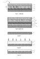
Figure 3 to 7 represent a cross-sectional view of a solar absorber body at different steps of the manufacturing method, according to one embodiment the invention, -
Figure 8 represents a cross-sectional view of a tube overcoated by a selective coating, according to one embodiment of the invention. - The coating thickness of each layer is shown much greater than it actually is in order to simplify the illustrations. The drawings are not necessarily to scale.
-
Figures 3 to 7 represents schematically the method for manufacturing asolar absorber body 1, including the following steps: - providing a
substrate 2, - depositing a
diffusion barrier layer 7 on the outer surface of thesubstrate 2 by thermal spraying, thediffusion barrier layer 7 comprising at least one refractory material, thediffusion barrier layer 7 having a roughness, less than or equal to 0.4µm, and preferentially between 0.1µm and 0.4µm. - Initially, as represented in
Figure 3 , asubstrate 2 is provided. Thesubstrate 2 can be planar, curved or tubular. Thesubstrate 2 may therefore be an uncoated or coated material. Thesubstrate 2 can be selected among various metals or metals compounds. - According to a preferential embodiment, the
substrate 2 is an uncoated tube. A heat transfer medium can flow through the interior of the tube. The heat transfer medium can be a fluid, e.g. oil or water vapour. - The thickness of the tube is preferably between 1,25 mm and 6,35 mm depending on the operating pressure and temperature. Furthermore, advantageously it is a cold drawn seamless tube to get excellent mechanical properties at high temperature and in particular under pressure. The preferred target range of temperature is 150°C-600°C, and more particularly between 300°C and 600°C, the pressure range is, advantageously, 2bar-200bar, and more particularly between 50bar and 200bar.
- The tube may be made of an iron, nickel or titanium alloy, the principal alloying elements, in terms of percentage per weight, of these alloys being iron, nickel or titanium respectively. In particular, the
substrate 2 is a steel tube. The tube may be a stainless steel tube. The tube is preferably a low alloy steel tube or a high alloy steel tube. These grades of steel contain less than 12.5% by weight of chromium. These steels are different from stainless steels, which usually contain more than 12.5% by weight of chromium. These steels usually have better mechanical properties, for example higher Young's Modulus, and are cheaper especially because they do not contain any nickel. Nevertheless, they do not form thin passive layer mainly constituted of Cr2O3, Al2O3, SiO2 or MgO as the usual stainless steels do. - Low alloy steel constitutes a category of ferrous materials that exhibit relevant mechanical properties as the result of additions of alloying elements such as carbon, chromium, manganese and molybdenum. Total alloying elements can range up to 8% by weight. For example, P195GH, 13CrMo44 and 10CrMo9-10 are low alloy steel. They can be used up to temperatures between 350°C and 550°C under relatively harsh pressure conditions. By harsh pressure conditions, we understood a pressure between 50bar and 200bar.
- High alloy steels contain more alloying elements than the low alloy steel, the chromium content remaining less than 11 % by weight. They can be used for temperature up to 650°C while keeping a reasonable creep resistance. X10CrMoVNb9-1 and X11CrMoWVNb97 are, for instance, high alloy steels. These alloy steels are advantageously cheaper than stainless steels, especially those that contain nickel as alloying elements such as AISI 304 or 316. Advantageously, low alloy steel presents excellent thermal conductivity enhancing heat transfer from the substrate to the heat carrier medium. Preferably, the tube is a low-alloy steel tube, in particular made of 10CrMo9-10, which presents a good thermal conductivity, low coefficient of thermal expansion (for example, in the range 10-15 ppm/K between 20 and 550°C), low cost and good resistance to creep deformation.
- Prior to thermal spray, the outer surface of the tube can be roughened by corundum blasting so as to increase significantly the roughness of the surface. This promotes subsequent adhesion of the barrier layer to the substrate. In a preferred embodiment, the roughness, evaluated with the Ra measurement defined by NF ISO 4287, prior deposition of the diffusion barrier layer, is between 2 µm and 10 µm. Prior to subsequent treatment, the tube, after being roughened can be washed and/or rinsed to remove dirt or other contaminants from the surfaces of the tube.
- As represented in
Figure 4 , adiffusion barrier layer 7 is thermal sprayed onto the outer surface ofsubstrate 2. Thediffusion barrier layer 7 is in direct contact with thesubstrate 2. As thesubstrate 2 is preferably a tube, the outer surface is understood to be a surface that extends on the one hand over the length of the tube and on the other hand over a circular arc. - In a preferred embodiment, the
diffusion barrier layer 7 extends to an uniform height over the circumference of the tube. Additionally, the barrier layer preferably covers the full length of the tube. Therefore, all or essentially all the outer surface of the tube is coated with the barrier layer. - Thermal spraying is a coating process in which a material is heated for example by electrical means, for instance this is the case of plasma spraying, and then sprayed onto a surface. It can provide thick coatings over large areas at high deposition rates as compared to thermal oxidation for example or physical vapour deposition (PVD) or chemical vapour deposition (CVD) process. It allows processing times to be shortened and throughput to be increased.
- The
diffusion barrier layer 7 may be deposited by any thermal spraying methods. Deposition by plasma spraying or high velocity oxygen fuel spraying is preferable compare to lower particle velocity coating method in order to obtain a barrier layer with high density. - Moreover, the coatings obtained by these plasma spray techniques present high bond strength and provide protection against high temperature oxidation and corrosion. Various shapes of substrates can advantageously be coated, such as plates, tubes, shells, etc.
- The composition of the
diffusion barrier layer 7 does not depend of the composition of thesubstrate 2. Many coatings can be deposited, for example ceramic, metallic layers, cermet layers or corrosion-resistant alloys. - In a preferred embodiment, a
diffusion barrier layer 7 comprising at least one refractory material is deposited onto the tube. What is meant here by refractory material is a material chemically and physically stable at high temperatures, for example above 300°C. This material possesses high melting points. Aluminium, chromium, silicon, zirconium and magnesium oxides as well as silicon carbide, tungsten carbide, boron nitride, zirconium diboride or Cobalt-Chromium alloys are considered to be refractory materials for example. - Refractory materials comprise refractory metals. For example, molybdenum, niobium, tantalum, tungsten and rhenium are refractory metals. A wider definition of refractory metals includes also other metals such as titanium, vanadium, chromium, zirconium, hafnium, osmium, ruthenium and iridium. Preferentially, the chemical composition of the barrier layer is different from the chemical composition of the substrate.
- The deposited materials advantageously present reflective optical properties preferentially in the spectral range of wavelength (λ) superior to 1,5 µm. By reflective properties, we understood that the percentage of incident radiation reflected by the deposited materials is at least 70% and preferably more than 85%. Any suitable reflective material may be used, taking into account factors such as but not limited to the wavelength of light to be reflected (preferably a spectral range of λ>1,5 µm) and cost.
- In a preferred embodiment, the refractory metal is made from molybdenum or tungsten, is a nickel-chromium base alloy, ZrB2 or a mixture of ZrB2 and SiC. Said nickel-chromium base alloy advantageously contains chromium, iron, silicon and boron. These materials present, advantageously, intrinsic infrared mirror properties, i.e the incident infrared light is reflected. Preferably more than 75% of the incident infrared light is reflected. What is meant by infrared light is an electromagnetic radiation with wavelengths comprise between 1,4 µm and 1000 µm, from short wavelength to far infrared. Cheaper materials such as Cr2O3, cobalt-chromium alloys, WC, Al2O3 could also be used, even if their optical properties are not as good as the first group cited. Preferentially, the barrier layer is a stainless alloy. By stainless material, it should be understood a material spontaneously forming a stable passivation layer such as for instance chromina, magnesia, alumina, silica when subject to oxidant atmosphere such a air.
- Advantageously, the
diffusion barrier layer 7 reduces or prevents diffusion of any oxidizing species such as O2 or its ions from the atmosphere to thesubstrate 2, or on the contrary from atoms of thesubstrate 2 into the solar absorber layer and/or from the outer layer to thesubstrate 2. The comprehensive prevention of O2 and its ions diffusion within the substrate can thus be guaranteed, especially oxygen in air can't diffuse significantly from the outer layer to the steel substrate, even at high temperature. Thus, it is possible to use alloy steel substrate rather than stainless steel substrates. Indeed, once alloy steel substrates are protected from oxidation, phenomenon appearing especially in air at high temperature, they are promising candidates for solar absorber body applications in term of mechanical properties and cost. - The thickness of the
diffusion barrier layer 7 is more than 25 µm. Preferably, the thickness is between 40 µm and 200 µm. If the thickness is too thin, the diffusion of O2 can occur through thediffusion barrier layer 7 and if the layer is too thick, in addition to the cost increase, cracking and peeling could damage said barrier layer. Therefore, this thickness range is a good compromise. - In a preferred embodiment, prior to depositing the next layer, for example, prior to depositing the
solar absorption layer 5, the method comprises polishing (arrows inFigure 4 ) thediffusion barrier layer 7. Preferably, thediffusion barrier layer 7 is polished until the surface roughness Ra is less than or equal to 0.4µm, and preferentially between 0.1µm and 0.4µm. This polishing step improves the reflectivity of thediffusion layer 7. For example, at 450°C, the infrared emissivity of a molybdenum layer decreases by 20% after polishing from Ra>2 µm to Ra<0,4µm. Finest is the polishing, lower the roughness and the emissivity are. For roughness lower than 0,1µm, a decrease in the roughness has not any more significant effect on the emissivity. - In a particular embodiment, the polishing is an electrochemical machining. Electrochemical machining (ECM) is a method to remove metal by an electrochemical process. A DC power supply is connected to the workpiece immersed in the electrolytic solution. The electrolyte is advantageously an acid solution such as a solution containing sulfuric, nitric or hydrochloric acid or a basic solution such as a solution containing potassium or sodium hydroxide.
- For example, the process is achieved at current densities of about 10A/cm2 and at relative low voltage from 5V to 30 V (continue or pulse). In some embodiments, a NaNO3 solution at 300 g/I is used. These experimental conditions enable to obtain a reasonable polishing duration less than 10 minutes.
- The rate of material machining does not depend on the mechanical properties. Advantageously, the odd-shape angles and intricate contours can be easily removed from the piece to be polished. High removal rates can be reached with no thermal or mechanical stresses, as compared as other polishing methods.
- Prior to ECM, the workpiece could be cleaned and/or rinsed.
- Rinsing steps, for example in demineralized water, can also follow the electrochemical machining to remove residual electrolyte and by-products ECM reaction. A drying step could also be performed.
- According to an alternative embodiment, the polishing is a mechanical grinding. Mechanical grinding removes material from the workpiece by abrasion, preferably using an abrasive belt or a flap wheel. They are suitable for grinding all types of contour and profile surfaces. Polishing involves using one or more wheels or belts to abrade the passivation layer. Abrasive material, grain size, grain spacing are essential parameters in mechanical grinding process. Wet or dry mechanical grinding operations can be made. The abrasive material is selected according to the hardness of the workpiece material. Aluminium oxide, silicon carbide or boron nitride can be used. Advantageously, aluminium oxide grains are selected. Two successive polishing are realized, the first one with a grain size of 100 so as to obtain a fast cutting and the second one with a grain size of 500 so as to obtain a precise and uniform work finishing. Preferably, the polishing is performed in dry conditions to prevent surface pollution with organic elements. Organic elements such as grease can decrease the adherence of the following layer to be deposited onto the passivation layer.
- In another particular embodiment, the surface roughness performances could be achieved by using a mechanical cold forming process Thus, the substrate could be processed through a die (and respectively an inside mandrel if tubes are processed) of hard metal (preferably made of carbide compound) where either the wall thickness and diameter of the substrate are processed. Cold forming factors should be designed so that the roughness ratio decreases. Lubricant such as soap, reactive oil or forming oil, or any other type of product is used to assist the cold forming process. Using such a method on low (respectively medium) alloy steels could ensure a reduction of the roughness by 2 or 5 times depending on the type of lubricant, the relevant cold forming factors, and the initial state.
- As an alternative embodiment, the use of the stable oxides of the substrate specifically obtained during the processing routes of the substrate could be such a layer.
- Depending on the chemical and physical properties of the
diffusion barrier layer 7, electrochemical machining, mechanical grinding or mechanical forming processing or none of these processes would be chosen. - In a particular embodiment, a thermal treatment is applied to the
diffusion barrier layer 7 after polishing. The temperature of said thermal treatment is preferably between 150°C and 950°C and the duration of said thermal treatment is preferably between 10 minutes and 1000 minutes. Preferably, the thermal treatment is realized under oxidizing atmosphere. By oxidizing atmosphere, it should be understood, generally, air, oxygen or water-enriched air, the atmosphere containing at least 5% in volume of a precursor such as oxygen, for example O2. Such a thermal treatment is realized so as to stabilize thediffusion barrier layer 7 after polishing. - Subsequently, a
solar absorption layer 5 is deposited onto thediffusion barrier layer 7. Thesolar absorption layer 5 is in direct contact with thediffusion barrier layer 7. Preferably, thesolar absorption layer 5 is not in contact with the substrate 2: thediffusion barrier layer 7 is located between thesubstrate 2 and thesolar absorption layer 5. - The
solar absorption layer 5 can also be a stack, comprising several layers that produce the desired optical properties. The optical properties are usually obtained by combining a highly reflecting coating (called IR-mirror), a layer that has a high solar absorption and a low IR-emissivity, and an antireflecting layer that improves the solar absorption. - The
solar absorption layer 5 can be deposited by physical vapour deposition. A stack comprising a platinum-based IR-mirror together with a cermet of Cr/Cr2O3, Mo/Al2O3 or W/Al2O3 with a SiO2 antireflecting layer on top of it could for instance be used. Another option for the elaboration of thesolar absorption layer 5 could be to use a selective painting containing high temperature resistant pigments, with or without the addition of a SiO2 antireflecting layer. Thesolar absorption layer 5 absorbs a high percentage of incident solar light and emits a percentage of the energy absorbed as radiated heat. Preferentially, the target is to absorb more than 80% of the incoming solar light, whereas the emissivity should stay under 25% of the emissivity of a black body at the working temperature of the absorber. - Preferably, the
solar absorber body 1 has a high spectral absorption capacity over the solar wavelength range, i.e. the absorber body absorbs the incident solar radiation and convert it into another energy, i.e. heat, which is transferred by conduction to the adjacent layer. By high absorption capacity, we understood that the material absorbs between more than 80% of the incident solar radiation in the spectral range 300nm<λ<1600nm and by high yield of incident radiation, we understood that the thermal and optical losses in the solar absorber body are less than 25%. The losses can be quantified by spectrophotometry for example. This means that thesolar absorption body 1 does only radiate back a small amount of heat and only loses a slight amount of incident solar radiation through reflection. - The
selective coating 3 illustrated onfigures 6 and 7 comprises adiffusion barrier layer 7, asolar absorption layer 5 and optionally anantireflective layer 6. - An additional layer, the
antireflective layer 6, can be deposited on top of thesolar absorption layer 5. The topmost layer of theantireflective layer 6 can be textured to increase solar absorption and minimize surface reflection. Texturing can be applied by any suitable methods. - In another embodiment, the
selective coating 3 could also comprise an additional infraredreflective layer 4. This infraredreflective layer 4 could be deposited between thediffusion barrier layer 7 and thesolar absorber layer 5. However, this layer can be completely omitted, since it has been discovered that for suitable materials and polishing of thediffusion barrier layer 7, said barrier layer has infrared mirror properties. - As represented in
Figure 8 , the obtainedsolar absorber body 1 comprises from the innermost layer to the outermost layer: - a
tube substrate 2, in which flows a heat carrier medium 8 (arrow inFigure 8 ), - a
diffusion barrier layer 7 comprising a refractory material, in direct contact with the outer surface of the tube, the thickness of saiddiffusion barrier layer 7 being more than 25 µm and the refractory material being preferentially chosen among molybdenum or tungsten, a nickel-chromium base alloy, ziconium diboride, or a mixture of ziconium diboride and silicon carbide. Additionally, in a particular embodiment, asolar absorption layer 5 in direct contact with thediffusion barrier layer 7 can be deposited, thesolar absorption layer 5 being separated from the tube by thediffusion barrier layer 7. An additionalantireflective layer 6 can also be deposited on top of thesolar absorption layer 5. - The refractory material could also be chosen among materials such as Cr2O3, a cobalt-chromium alloy, WC, or Al2O3.
- The
diffusion barrier layer 7, advantageously, is constituted by refractory materials or a single refractory material. - The tube of the
solar absorber body 1 is made of steel with a chromium content less than 12,5% by weight and in particular, the tube is made of low-alloy steel, the total alloy content being less than 8% by weight. - In a preferred embodiment, the
diffusion barrier layer 7 has a thickness between 40 µm and 200 µm.
Thediffusion barrier layer 7 has a roughness between 0.1µm and 0.4µm. - In a preferred embodiment, the
solar absorber body 1 is constituted of: - a
tube substrate 2, in which flows aheat carrier medium 8, - a
diffusion barrier layer 7; thediffusion barrier layer 7 is preferentially elaborated from a powder of ZrB2, which can contain less than 10% by volume of an additional element such as SiC. The additional element is, advantageously, also in powder form. Preferentially, thediffusion barrier layer 7 is only constituted of ZrB2 or is only constituted of ZrB2 and SiC. - an
antireflective layer 6 on top of thediffusion barrier layer 7. - In this particular
solar absorber body 1, thediffusion barrier layer 7 acts as a solar absorption layer. - Advantageously, the
antireflective layer 6 enables to obtain improved performances. - An embodiment employs the
solar absorber body 1 described above in solar energy applications and in particular in a concentrating solar power system designed to collect heat by absorbing sunlight. They comprise a solar concentrator so as to concentrate and focus sunlight onto the solar absorber body containing the heat transfer fluid. The solar absorber body absorbs then the sunlight and convert it to heat, which is transmitted to the heat transfer fluid. The temperature of the fluid then strongly increases and can be used to heat steam in a standard turbine generator for electricity generation. - In particular, this includes Fresnel lenses, mirrors, solar power towers and parabolic troughs collectors.
- During the different steps, deposition and/or rinsing, the tube can be sealed at each end by any suitable caps to prevent contamination inside the tube.
- The method for manufacturing the
solar absorber body 1 described in the foregoing is simple to implement and relatively inexpensive. It enables to obtain thickdiffusion barrier layers 7 between the tube and the adjacent layers. This reduces and/or prevents O2 diffusion and ensures a long-term stability, even at high temperature, of material. Therefore, thesolar absorber body 1 exhibits long service life at high temperature. - The method provides high thermal and structural stabilities for the combined layers, excellent adhesion between the
substrate 2 and the adjacent layers and between thediffusion barrier layer 7 and the adjacent layers, enhanced resistance to thermal and mechanical stresses and acceptable thermal conductivity. - Moreover, as the substrate is stable at temperature higher than 400°C under atmospheric conditions, the
selective coating 3 presents long-life performances: it is stable during 25 years. - Additionally, the coating is mechanically stable and highly oxidation-resistant: structural modifications and oxidation of the
substrate 2 are for example prevented thanks to the presence of thediffusion barrier layer 7 according to the invention. With such a diffusion barrier layer, even substrates made of instable materials under oxygen (such as low-alloy steel materials) can be used. - Finally, it presents both high absorption and low emission properties: an absorption more than 90% of the incident light and an infrared emission lower than 20% as compared to a black body reference at 450°C.
- The invention is not limited to the embodiments described above for non-restrictive example purposes. Although the example given is that of a steel tube, the manufacturing process could be applied to other tube materials.
Claims (23)
- A method for manufacturing a solar absorber body (1), said method comprising the steps of:- providing a tube designed to contain a heat transfer medium,- depositing a diffusion barrier layer (7) on the outer surface of the tube, the diffusion barrier layer (7) comprising at least a refractory material, characterized in that the diffusion barrier layer 7 is deposited by thermal spraying
and characterized in that the diffusion barrier layer (7) has a roughness, prior to depositing the solar absorption layer 5, less than or equal to 0.4µm, and preferentially between 0.1µm and 0.4µm. - A method according to claim 1, characterized in that it comprises depositing an antireflective layer (6) on top of the diffusion barrier layer (7).
- A method according to claim 1, characterized in that it comprises depositing a solar absorption layer (5) over said diffusion barrier layer (7).
- A method according to claim 3, characterized in that it comprises depositing an antireflective layer (6) on top of the solar absorption layer (5).
- A method according to any one of claims 1 to 4, characterized in that thermal spraying is plasma spraying or high velocity oxygen fuel spraying.
- A method according to any one of claims 1 to 5, characterized in that the diffusion barrier layer (7) has a thickness more than 25 µm, and preferentially between 40 µm and 200 µm.
- A method according to any one of claims 1 to 6, characterized in that the refractory material is selected among molybdenum, tungsten, Al2O3, Cr2O3, a nickel-chromium alloy, a cobalt-chromium alloy, WC or ZrB2, or a mixture of SiC and ZrB2.
- A method according to any one of claims 1 to 7, characterized in that it comprises polishing the diffusion barrier layer (7) prior to depositing the solar absorption layer (5) or the antireflective layer (6).
- A method according to claim 8, characterized in that polishing is an electrochemical machining, a mechanical grinding or a mechanical forming process.
- A method according to any one of claims 8 to 9, characterized in that a thermal treatment is applied to the diffusion barrier layer (7) after polishing, the temperature of said thermal treatment being between 150°C and 950°C and the duration of said thermal treatment being between 10 minutes and 1000 minutes.
- A method according to any one of claims 1 to 10, characterized in that the tube is made of steel with a chromium content less than 12.5% by weight.
- A method according to claim 11, characterized in that the steel material contains less than 8 % by weight of allowing elements.
- A method according to claim 12, characterized in that the steel material is chosen among P195GH, 13CrMo44, 10CrMo9-10,
- A method according to claim 11, characterized in that the steel material is chosen among X10CrMoVNb9-1 and X11CrMoWVNb97.
- A solar absorber body (1) comprising:- a tube,- a diffusion barrier layer (7) comprising at least a refractory material, in direct contact with the outer surface of the tube, the thickness of said diffusion barrier layer (7) being more than 25 µm.
- A solar absorber body (1) according to claim 15, characterized in that it comprises a solar absorption layer (5) in direct contact with the diffusion barrier layer (7), the solar absorption layer (5) being separated from the tube by the diffusion barrier layer (7).
- A solar absorber body (1) according to claim 15, characterized in that it comprises an antireflective layer (6) in direct contact with the diffusion barrier layer (7), the antireflective layer (6) being separated from the tube by the diffusion barrier layer (7).
- A solar absorber body according to any one of the claims 15 to 17, characterized in that the refractory material is selected among molybdenum, tungsten, Al2O3, Cr2O3, a nickel-chromium alloy, a cobalt-chromium alloy, WC, ZrB2, or a mixture of ZrB2 and SiC.
- A solar absorber body according to any one of claims 15 to 18, characterized in that the tube is made of steel with a chromium content less than 12.5 % by weight.
- A solar absorber body according to claim 19, characterized in that the tube is made of low-alloy steel.
- A solar absorber body according to any one of claims 15 to 20, characterized in that the diffusion barrier layer (7) has a thickness between 40 µm and 200 µm.
- A solar absorber body according to any one of claims 15 to 21, characterized in that the diffusion barrier layer (7) has a roughness between 0.1µm and 0.4µm.
- A concentrating solar power system comprising a solar absorber body (1) according to any one of claims 15 to 22.
Priority Applications (2)
| Application Number | Priority Date | Filing Date | Title |
|---|---|---|---|
| EP13354015.3A EP2801767A1 (en) | 2013-05-06 | 2013-05-06 | Method for manufacturing a solar absorber body, a solar absorber body and a concentrating solar power system comprising said solar absorber body. |
| PCT/IB2014/001578 WO2014191835A2 (en) | 2013-05-06 | 2014-05-06 | Method for manufacturing a solar absorber body, a solar absorber body and a concentrating solar power system comprising said solar absorber body |
Applications Claiming Priority (1)
| Application Number | Priority Date | Filing Date | Title |
|---|---|---|---|
| EP13354015.3A EP2801767A1 (en) | 2013-05-06 | 2013-05-06 | Method for manufacturing a solar absorber body, a solar absorber body and a concentrating solar power system comprising said solar absorber body. |
Publications (1)
| Publication Number | Publication Date |
|---|---|
| EP2801767A1 true EP2801767A1 (en) | 2014-11-12 |
Family
ID=48669830
Family Applications (1)
| Application Number | Title | Priority Date | Filing Date |
|---|---|---|---|
| EP13354015.3A Withdrawn EP2801767A1 (en) | 2013-05-06 | 2013-05-06 | Method for manufacturing a solar absorber body, a solar absorber body and a concentrating solar power system comprising said solar absorber body. |
Country Status (2)
| Country | Link |
|---|---|
| EP (1) | EP2801767A1 (en) |
| WO (1) | WO2014191835A2 (en) |
Cited By (3)
| Publication number | Priority date | Publication date | Assignee | Title |
|---|---|---|---|---|
| WO2015097333A1 (en) * | 2013-12-27 | 2015-07-02 | Abengoa Solar New Technologies, S.A. | Absorbent coatings for solar central receivers and method for preparing said coatings in situ |
| EP3724558A4 (en) * | 2018-02-22 | 2021-08-25 | Absolicon Solar Collector AB | Electroplating of selective surfaces for concentrating solar collectors |
| EP3835682A4 (en) * | 2018-08-09 | 2021-09-08 | Kabushiki Kaisha Toyota Jidoshokki | SOLAR HEAT COLLECTION PIPE |
Citations (8)
| Publication number | Priority date | Publication date | Assignee | Title |
|---|---|---|---|---|
| US4166880A (en) * | 1978-01-18 | 1979-09-04 | Solamat Incorporated | Solar energy device |
| US5166002A (en) * | 1988-12-05 | 1992-11-24 | Martin Marietta Corporation | High-temperature, high-emissivity, optically black boron surface |
| DE19933050A1 (en) * | 1998-09-17 | 2000-04-06 | Karl Berreth | Solar collector, used for domestic water and/or space heating or for seawater desalination plants, has a thermally sprayed solar absorption coating containing titanium oxide or iron oxide |
| US20090208761A1 (en) | 2008-02-20 | 2009-08-20 | Silmy Kamel | Radiation-selective absorber coating, absober tube and process for production thereof |
| WO2009140051A2 (en) | 2008-05-14 | 2009-11-19 | Ausra, Inc. | Methods and compositions for coating devices |
| US20110232723A1 (en) * | 2008-08-29 | 2011-09-29 | Dieter Ostermann | Layer system for solar absorber |
| US20120180783A1 (en) * | 2009-09-30 | 2012-07-19 | Krueger Ursus | Central tube for a linear concentrating solar thermal power plant, having an absorber layer, and method for applying said absorber layer |
| WO2012145283A1 (en) * | 2011-04-17 | 2012-10-26 | Brightsource Industries (Israel) Ltd. | Solar-radiation-absorbing formulations and related apparatus and methods |
-
2013
- 2013-05-06 EP EP13354015.3A patent/EP2801767A1/en not_active Withdrawn
-
2014
- 2014-05-06 WO PCT/IB2014/001578 patent/WO2014191835A2/en not_active Ceased
Patent Citations (8)
| Publication number | Priority date | Publication date | Assignee | Title |
|---|---|---|---|---|
| US4166880A (en) * | 1978-01-18 | 1979-09-04 | Solamat Incorporated | Solar energy device |
| US5166002A (en) * | 1988-12-05 | 1992-11-24 | Martin Marietta Corporation | High-temperature, high-emissivity, optically black boron surface |
| DE19933050A1 (en) * | 1998-09-17 | 2000-04-06 | Karl Berreth | Solar collector, used for domestic water and/or space heating or for seawater desalination plants, has a thermally sprayed solar absorption coating containing titanium oxide or iron oxide |
| US20090208761A1 (en) | 2008-02-20 | 2009-08-20 | Silmy Kamel | Radiation-selective absorber coating, absober tube and process for production thereof |
| WO2009140051A2 (en) | 2008-05-14 | 2009-11-19 | Ausra, Inc. | Methods and compositions for coating devices |
| US20110232723A1 (en) * | 2008-08-29 | 2011-09-29 | Dieter Ostermann | Layer system for solar absorber |
| US20120180783A1 (en) * | 2009-09-30 | 2012-07-19 | Krueger Ursus | Central tube for a linear concentrating solar thermal power plant, having an absorber layer, and method for applying said absorber layer |
| WO2012145283A1 (en) * | 2011-04-17 | 2012-10-26 | Brightsource Industries (Israel) Ltd. | Solar-radiation-absorbing formulations and related apparatus and methods |
Non-Patent Citations (1)
| Title |
|---|
| KENNEDY C: "Review of Mid- to high-temperature Solar Reflective Absorber Materials", TECHNICAL REPORT OF THE NATIONAL ENERGY LABORATORY, 2002 |
Cited By (3)
| Publication number | Priority date | Publication date | Assignee | Title |
|---|---|---|---|---|
| WO2015097333A1 (en) * | 2013-12-27 | 2015-07-02 | Abengoa Solar New Technologies, S.A. | Absorbent coatings for solar central receivers and method for preparing said coatings in situ |
| EP3724558A4 (en) * | 2018-02-22 | 2021-08-25 | Absolicon Solar Collector AB | Electroplating of selective surfaces for concentrating solar collectors |
| EP3835682A4 (en) * | 2018-08-09 | 2021-09-08 | Kabushiki Kaisha Toyota Jidoshokki | SOLAR HEAT COLLECTION PIPE |
Also Published As
| Publication number | Publication date |
|---|---|
| WO2014191835A3 (en) | 2015-02-05 |
| WO2014191835A2 (en) | 2014-12-04 |
Similar Documents
| Publication | Publication Date | Title |
|---|---|---|
| Cao et al. | A review of cermet-based spectrally selective solar absorbers | |
| CN102575359B (en) | Central pipe with absorber layer for linear concentrated solar thermal power plant and method for applying said absorber layer | |
| EP2780646B1 (en) | Solar-thermal conversion member, solar-thermal conversion stack, solar-thermal conversion device and solar thermal power generation device | |
| US8318329B2 (en) | Radiation-selective absorber coating, absorber tube and process for production thereof | |
| TW201122387A (en) | Optically active multilayer system for solar absorption | |
| US8555871B2 (en) | Radiation-selective absorber coating and absorber tube with said radiation-selective absorber coating | |
| JP2010271033A (en) | Radiation-selective absorber coating and absorber tube treated with radiation-selective absorber coating | |
| ITTO20070855A1 (en) | SELECTIVE RADIATION ABSORBENT COATING, ABSORBER TUBE AND PROCEDURE FOR ITS MANUFACTURING | |
| EP2245208A2 (en) | Method for producing a cermet-based spectrally selective coating and material thus obtained | |
| WO2014191835A2 (en) | Method for manufacturing a solar absorber body, a solar absorber body and a concentrating solar power system comprising said solar absorber body | |
| CN106884145B (en) | A kind of coating for selective absorption of sunlight spectrum and preparation method thereof | |
| JP2019095187A (en) | Coated component of photovoltaic generation system and method for manufacturing the same | |
| EP1759031B1 (en) | Spectrally selective surface coating of the receiver tube of a solar concentrator, and method for the manufacture thereof | |
| CN105779926B (en) | Prepare the new process for being used for high temperature solar energy selective absorption coating under atmospheric environment | |
| US20190128566A1 (en) | Solar selective coating | |
| CN104152848B (en) | A kind of double-deck photothermal deformation composite and preparation method thereof | |
| EP3410030B1 (en) | Solar heat collection tube and production method therefor | |
| WO2006006995A1 (en) | Smooth outer coating for combustor components and coating method therefor | |
| CN111727349A (en) | Electroplating of Selective Surfaces for Concentrating Solar Collectors | |
| Sandeep et al. | Advancement of solar selective DLC coating using capvd for solar thermal applications | |
| EP2530496A1 (en) | High reflectance temperature resistant aluminium based mirror reflectors | |
| CN202254444U (en) | High weather-resistant selective absorption coating based on aluminum material | |
| JP2011073113A (en) | Double-coated diamond abrasive particle and method of manufacturing the same | |
| US20200370789A1 (en) | High performance thermally-sprayed absorber coating | |
| CN201992892U (en) | Metallic aluminum solar heat collecting tube |
Legal Events
| Date | Code | Title | Description |
|---|---|---|---|
| PUAI | Public reference made under article 153(3) epc to a published international application that has entered the european phase |
Free format text: ORIGINAL CODE: 0009012 |
|
| 17P | Request for examination filed |
Effective date: 20130506 |
|
| AK | Designated contracting states |
Kind code of ref document: A1 Designated state(s): AL AT BE BG CH CY CZ DE DK EE ES FI FR GB GR HR HU IE IS IT LI LT LU LV MC MK MT NL NO PL PT RO RS SE SI SK SM TR |
|
| AX | Request for extension of the european patent |
Extension state: BA ME |
|
| R17P | Request for examination filed (corrected) |
Effective date: 20150512 |
|
| RBV | Designated contracting states (corrected) |
Designated state(s): AL AT BE BG CH CY CZ DE DK EE ES FI FR GB GR HR HU IE IS IT LI LT LU LV MC MK MT NL NO PL PT RO RS SE SI SK SM TR |
|
| 17Q | First examination report despatched |
Effective date: 20151223 |
|
| STAA | Information on the status of an ep patent application or granted ep patent |
Free format text: STATUS: THE APPLICATION IS DEEMED TO BE WITHDRAWN |
|
| 18D | Application deemed to be withdrawn |
Effective date: 20160503 |