EP2801723B1 - Solar energy and external source steam complementary power generation apparatus - Google Patents
Solar energy and external source steam complementary power generation apparatus Download PDFInfo
- Publication number
- EP2801723B1 EP2801723B1 EP12858668.2A EP12858668A EP2801723B1 EP 2801723 B1 EP2801723 B1 EP 2801723B1 EP 12858668 A EP12858668 A EP 12858668A EP 2801723 B1 EP2801723 B1 EP 2801723B1
- Authority
- EP
- European Patent Office
- Prior art keywords
- solar
- steam
- water
- turboset
- switch valve
- Prior art date
- Legal status (The legal status is an assumption and is not a legal conclusion. Google has not performed a legal analysis and makes no representation as to the accuracy of the status listed.)
- Not-in-force
Links
Images
Classifications
-
- H—ELECTRICITY
- H02—GENERATION; CONVERSION OR DISTRIBUTION OF ELECTRIC POWER
- H02S—GENERATION OF ELECTRIC POWER BY CONVERSION OF INFRARED RADIATION, VISIBLE LIGHT OR ULTRAVIOLET LIGHT, e.g. USING PHOTOVOLTAIC [PV] MODULES
- H02S10/00—PV power plants; Combinations of PV energy systems with other systems for the generation of electric power
-
- F—MECHANICAL ENGINEERING; LIGHTING; HEATING; WEAPONS; BLASTING
- F01—MACHINES OR ENGINES IN GENERAL; ENGINE PLANTS IN GENERAL; STEAM ENGINES
- F01D—NON-POSITIVE DISPLACEMENT MACHINES OR ENGINES, e.g. STEAM TURBINES
- F01D17/00—Regulating or controlling by varying flow
-
- F—MECHANICAL ENGINEERING; LIGHTING; HEATING; WEAPONS; BLASTING
- F01—MACHINES OR ENGINES IN GENERAL; ENGINE PLANTS IN GENERAL; STEAM ENGINES
- F01D—NON-POSITIVE DISPLACEMENT MACHINES OR ENGINES, e.g. STEAM TURBINES
- F01D17/00—Regulating or controlling by varying flow
- F01D17/02—Arrangement of sensing elements
-
- F—MECHANICAL ENGINEERING; LIGHTING; HEATING; WEAPONS; BLASTING
- F01—MACHINES OR ENGINES IN GENERAL; ENGINE PLANTS IN GENERAL; STEAM ENGINES
- F01D—NON-POSITIVE DISPLACEMENT MACHINES OR ENGINES, e.g. STEAM TURBINES
- F01D17/00—Regulating or controlling by varying flow
- F01D17/02—Arrangement of sensing elements
- F01D17/04—Arrangement of sensing elements responsive to load
-
- F—MECHANICAL ENGINEERING; LIGHTING; HEATING; WEAPONS; BLASTING
- F01—MACHINES OR ENGINES IN GENERAL; ENGINE PLANTS IN GENERAL; STEAM ENGINES
- F01D—NON-POSITIVE DISPLACEMENT MACHINES OR ENGINES, e.g. STEAM TURBINES
- F01D17/00—Regulating or controlling by varying flow
- F01D17/02—Arrangement of sensing elements
- F01D17/06—Arrangement of sensing elements responsive to speed
-
- F—MECHANICAL ENGINEERING; LIGHTING; HEATING; WEAPONS; BLASTING
- F01—MACHINES OR ENGINES IN GENERAL; ENGINE PLANTS IN GENERAL; STEAM ENGINES
- F01D—NON-POSITIVE DISPLACEMENT MACHINES OR ENGINES, e.g. STEAM TURBINES
- F01D17/00—Regulating or controlling by varying flow
- F01D17/02—Arrangement of sensing elements
- F01D17/08—Arrangement of sensing elements responsive to condition of working-fluid, e.g. pressure
-
- F—MECHANICAL ENGINEERING; LIGHTING; HEATING; WEAPONS; BLASTING
- F01—MACHINES OR ENGINES IN GENERAL; ENGINE PLANTS IN GENERAL; STEAM ENGINES
- F01D—NON-POSITIVE DISPLACEMENT MACHINES OR ENGINES, e.g. STEAM TURBINES
- F01D17/00—Regulating or controlling by varying flow
- F01D17/02—Arrangement of sensing elements
- F01D17/08—Arrangement of sensing elements responsive to condition of working-fluid, e.g. pressure
- F01D17/085—Arrangement of sensing elements responsive to condition of working-fluid, e.g. pressure to temperature
-
- F—MECHANICAL ENGINEERING; LIGHTING; HEATING; WEAPONS; BLASTING
- F01—MACHINES OR ENGINES IN GENERAL; ENGINE PLANTS IN GENERAL; STEAM ENGINES
- F01D—NON-POSITIVE DISPLACEMENT MACHINES OR ENGINES, e.g. STEAM TURBINES
- F01D19/00—Starting of machines or engines; Regulating, controlling, or safety means in connection therewith
-
- F—MECHANICAL ENGINEERING; LIGHTING; HEATING; WEAPONS; BLASTING
- F01—MACHINES OR ENGINES IN GENERAL; ENGINE PLANTS IN GENERAL; STEAM ENGINES
- F01D—NON-POSITIVE DISPLACEMENT MACHINES OR ENGINES, e.g. STEAM TURBINES
- F01D19/00—Starting of machines or engines; Regulating, controlling, or safety means in connection therewith
- F01D19/02—Starting of machines or engines; Regulating, controlling, or safety means in connection therewith dependent on temperature of component parts, e.g. of turbine-casing
-
- F—MECHANICAL ENGINEERING; LIGHTING; HEATING; WEAPONS; BLASTING
- F01—MACHINES OR ENGINES IN GENERAL; ENGINE PLANTS IN GENERAL; STEAM ENGINES
- F01D—NON-POSITIVE DISPLACEMENT MACHINES OR ENGINES, e.g. STEAM TURBINES
- F01D21/00—Shutting-down of machines or engines, e.g. in emergency; Regulating, controlling, or safety means not otherwise provided for
-
- F—MECHANICAL ENGINEERING; LIGHTING; HEATING; WEAPONS; BLASTING
- F03—MACHINES OR ENGINES FOR LIQUIDS; WIND, SPRING, OR WEIGHT MOTORS; PRODUCING MECHANICAL POWER OR A REACTIVE PROPULSIVE THRUST, NOT OTHERWISE PROVIDED FOR
- F03G—SPRING, WEIGHT, INERTIA OR LIKE MOTORS; MECHANICAL-POWER PRODUCING DEVICES OR MECHANISMS, NOT OTHERWISE PROVIDED FOR OR USING ENERGY SOURCES NOT OTHERWISE PROVIDED FOR
- F03G6/00—Devices for producing mechanical power from solar energy
- F03G6/003—Devices for producing mechanical power from solar energy having a Rankine cycle
- F03G6/005—Binary cycle plants where the fluid from the solar collector heats the working fluid via a heat exchanger
-
- F—MECHANICAL ENGINEERING; LIGHTING; HEATING; WEAPONS; BLASTING
- F03—MACHINES OR ENGINES FOR LIQUIDS; WIND, SPRING, OR WEIGHT MOTORS; PRODUCING MECHANICAL POWER OR A REACTIVE PROPULSIVE THRUST, NOT OTHERWISE PROVIDED FOR
- F03G—SPRING, WEIGHT, INERTIA OR LIKE MOTORS; MECHANICAL-POWER PRODUCING DEVICES OR MECHANISMS, NOT OTHERWISE PROVIDED FOR OR USING ENERGY SOURCES NOT OTHERWISE PROVIDED FOR
- F03G6/00—Devices for producing mechanical power from solar energy
- F03G6/06—Devices for producing mechanical power from solar energy with solar energy concentrating means
- F03G6/061—Parabolic linear or trough concentrators
-
- F—MECHANICAL ENGINEERING; LIGHTING; HEATING; WEAPONS; BLASTING
- F03—MACHINES OR ENGINES FOR LIQUIDS; WIND, SPRING, OR WEIGHT MOTORS; PRODUCING MECHANICAL POWER OR A REACTIVE PROPULSIVE THRUST, NOT OTHERWISE PROVIDED FOR
- F03G—SPRING, WEIGHT, INERTIA OR LIKE MOTORS; MECHANICAL-POWER PRODUCING DEVICES OR MECHANISMS, NOT OTHERWISE PROVIDED FOR OR USING ENERGY SOURCES NOT OTHERWISE PROVIDED FOR
- F03G6/00—Devices for producing mechanical power from solar energy
- F03G6/06—Devices for producing mechanical power from solar energy with solar energy concentrating means
- F03G6/065—Devices for producing mechanical power from solar energy with solar energy concentrating means having a Rankine cycle
-
- F—MECHANICAL ENGINEERING; LIGHTING; HEATING; WEAPONS; BLASTING
- F03—MACHINES OR ENGINES FOR LIQUIDS; WIND, SPRING, OR WEIGHT MOTORS; PRODUCING MECHANICAL POWER OR A REACTIVE PROPULSIVE THRUST, NOT OTHERWISE PROVIDED FOR
- F03G—SPRING, WEIGHT, INERTIA OR LIKE MOTORS; MECHANICAL-POWER PRODUCING DEVICES OR MECHANISMS, NOT OTHERWISE PROVIDED FOR OR USING ENERGY SOURCES NOT OTHERWISE PROVIDED FOR
- F03G6/00—Devices for producing mechanical power from solar energy
- F03G6/06—Devices for producing mechanical power from solar energy with solar energy concentrating means
- F03G6/065—Devices for producing mechanical power from solar energy with solar energy concentrating means having a Rankine cycle
- F03G6/067—Binary cycle plants where the fluid from the solar collector heats the working fluid via a heat exchanger
-
- F—MECHANICAL ENGINEERING; LIGHTING; HEATING; WEAPONS; BLASTING
- F03—MACHINES OR ENGINES FOR LIQUIDS; WIND, SPRING, OR WEIGHT MOTORS; PRODUCING MECHANICAL POWER OR A REACTIVE PROPULSIVE THRUST, NOT OTHERWISE PROVIDED FOR
- F03G—SPRING, WEIGHT, INERTIA OR LIKE MOTORS; MECHANICAL-POWER PRODUCING DEVICES OR MECHANISMS, NOT OTHERWISE PROVIDED FOR OR USING ENERGY SOURCES NOT OTHERWISE PROVIDED FOR
- F03G6/00—Devices for producing mechanical power from solar energy
- F03G6/06—Devices for producing mechanical power from solar energy with solar energy concentrating means
- F03G6/068—Devices for producing mechanical power from solar energy with solar energy concentrating means having other power cycles, e.g. Stirling or transcritical, supercritical cycles; combined with other power sources, e.g. wind, gas or nuclear
-
- F—MECHANICAL ENGINEERING; LIGHTING; HEATING; WEAPONS; BLASTING
- F03—MACHINES OR ENGINES FOR LIQUIDS; WIND, SPRING, OR WEIGHT MOTORS; PRODUCING MECHANICAL POWER OR A REACTIVE PROPULSIVE THRUST, NOT OTHERWISE PROVIDED FOR
- F03G—SPRING, WEIGHT, INERTIA OR LIKE MOTORS; MECHANICAL-POWER PRODUCING DEVICES OR MECHANISMS, NOT OTHERWISE PROVIDED FOR OR USING ENERGY SOURCES NOT OTHERWISE PROVIDED FOR
- F03G6/00—Devices for producing mechanical power from solar energy
- F03G6/071—Devices for producing mechanical power from solar energy with energy storage devices
-
- F—MECHANICAL ENGINEERING; LIGHTING; HEATING; WEAPONS; BLASTING
- F22—STEAM GENERATION
- F22B—METHODS OF STEAM GENERATION; STEAM BOILERS
- F22B1/00—Methods of steam generation characterised by form of heating method
- F22B1/006—Methods of steam generation characterised by form of heating method using solar heat
-
- F—MECHANICAL ENGINEERING; LIGHTING; HEATING; WEAPONS; BLASTING
- F24—HEATING; RANGES; VENTILATING
- F24S—SOLAR HEAT COLLECTORS; SOLAR HEAT SYSTEMS
- F24S20/00—Solar heat collectors specially adapted for particular uses or environments
- F24S20/20—Solar heat collectors for receiving concentrated solar energy, e.g. receivers for solar power plants
-
- F—MECHANICAL ENGINEERING; LIGHTING; HEATING; WEAPONS; BLASTING
- F01—MACHINES OR ENGINES IN GENERAL; ENGINE PLANTS IN GENERAL; STEAM ENGINES
- F01K—STEAM ENGINE PLANTS; STEAM ACCUMULATORS; ENGINE PLANTS NOT OTHERWISE PROVIDED FOR; ENGINES USING SPECIAL WORKING FLUIDS OR CYCLES
- F01K11/00—Plants characterised by the engines being structurally combined with boilers or condensers
- F01K11/02—Plants characterised by the engines being structurally combined with boilers or condensers the engines being turbines
-
- Y—GENERAL TAGGING OF NEW TECHNOLOGICAL DEVELOPMENTS; GENERAL TAGGING OF CROSS-SECTIONAL TECHNOLOGIES SPANNING OVER SEVERAL SECTIONS OF THE IPC; TECHNICAL SUBJECTS COVERED BY FORMER USPC CROSS-REFERENCE ART COLLECTIONS [XRACs] AND DIGESTS
- Y02—TECHNOLOGIES OR APPLICATIONS FOR MITIGATION OR ADAPTATION AGAINST CLIMATE CHANGE
- Y02E—REDUCTION OF GREENHOUSE GAS [GHG] EMISSIONS, RELATED TO ENERGY GENERATION, TRANSMISSION OR DISTRIBUTION
- Y02E10/00—Energy generation through renewable energy sources
- Y02E10/40—Solar thermal energy, e.g. solar towers
-
- Y—GENERAL TAGGING OF NEW TECHNOLOGICAL DEVELOPMENTS; GENERAL TAGGING OF CROSS-SECTIONAL TECHNOLOGIES SPANNING OVER SEVERAL SECTIONS OF THE IPC; TECHNICAL SUBJECTS COVERED BY FORMER USPC CROSS-REFERENCE ART COLLECTIONS [XRACs] AND DIGESTS
- Y02—TECHNOLOGIES OR APPLICATIONS FOR MITIGATION OR ADAPTATION AGAINST CLIMATE CHANGE
- Y02E—REDUCTION OF GREENHOUSE GAS [GHG] EMISSIONS, RELATED TO ENERGY GENERATION, TRANSMISSION OR DISTRIBUTION
- Y02E10/00—Energy generation through renewable energy sources
- Y02E10/40—Solar thermal energy, e.g. solar towers
- Y02E10/44—Heat exchange systems
-
- Y—GENERAL TAGGING OF NEW TECHNOLOGICAL DEVELOPMENTS; GENERAL TAGGING OF CROSS-SECTIONAL TECHNOLOGIES SPANNING OVER SEVERAL SECTIONS OF THE IPC; TECHNICAL SUBJECTS COVERED BY FORMER USPC CROSS-REFERENCE ART COLLECTIONS [XRACs] AND DIGESTS
- Y02—TECHNOLOGIES OR APPLICATIONS FOR MITIGATION OR ADAPTATION AGAINST CLIMATE CHANGE
- Y02E—REDUCTION OF GREENHOUSE GAS [GHG] EMISSIONS, RELATED TO ENERGY GENERATION, TRANSMISSION OR DISTRIBUTION
- Y02E10/00—Energy generation through renewable energy sources
- Y02E10/40—Solar thermal energy, e.g. solar towers
- Y02E10/46—Conversion of thermal power into mechanical power, e.g. Rankine, Stirling or solar thermal engines
-
- Y—GENERAL TAGGING OF NEW TECHNOLOGICAL DEVELOPMENTS; GENERAL TAGGING OF CROSS-SECTIONAL TECHNOLOGIES SPANNING OVER SEVERAL SECTIONS OF THE IPC; TECHNICAL SUBJECTS COVERED BY FORMER USPC CROSS-REFERENCE ART COLLECTIONS [XRACs] AND DIGESTS
- Y02—TECHNOLOGIES OR APPLICATIONS FOR MITIGATION OR ADAPTATION AGAINST CLIMATE CHANGE
- Y02E—REDUCTION OF GREENHOUSE GAS [GHG] EMISSIONS, RELATED TO ENERGY GENERATION, TRANSMISSION OR DISTRIBUTION
- Y02E10/00—Energy generation through renewable energy sources
- Y02E10/50—Photovoltaic [PV] energy
-
- Y—GENERAL TAGGING OF NEW TECHNOLOGICAL DEVELOPMENTS; GENERAL TAGGING OF CROSS-SECTIONAL TECHNOLOGIES SPANNING OVER SEVERAL SECTIONS OF THE IPC; TECHNICAL SUBJECTS COVERED BY FORMER USPC CROSS-REFERENCE ART COLLECTIONS [XRACs] AND DIGESTS
- Y02—TECHNOLOGIES OR APPLICATIONS FOR MITIGATION OR ADAPTATION AGAINST CLIMATE CHANGE
- Y02E—REDUCTION OF GREENHOUSE GAS [GHG] EMISSIONS, RELATED TO ENERGY GENERATION, TRANSMISSION OR DISTRIBUTION
- Y02E20/00—Combustion technologies with mitigation potential
- Y02E20/16—Combined cycle power plant [CCPP], or combined cycle gas turbine [CCGT]
-
- Y—GENERAL TAGGING OF NEW TECHNOLOGICAL DEVELOPMENTS; GENERAL TAGGING OF CROSS-SECTIONAL TECHNOLOGIES SPANNING OVER SEVERAL SECTIONS OF THE IPC; TECHNICAL SUBJECTS COVERED BY FORMER USPC CROSS-REFERENCE ART COLLECTIONS [XRACs] AND DIGESTS
- Y02—TECHNOLOGIES OR APPLICATIONS FOR MITIGATION OR ADAPTATION AGAINST CLIMATE CHANGE
- Y02P—CLIMATE CHANGE MITIGATION TECHNOLOGIES IN THE PRODUCTION OR PROCESSING OF GOODS
- Y02P80/00—Climate change mitigation technologies for sector-wide applications
- Y02P80/10—Efficient use of energy, e.g. using compressed air or pressurized fluid as energy carrier
- Y02P80/15—On-site combined power, heat or cool generation or distribution, e.g. combined heat and power [CHP] supply
Definitions
- the invention relates to a power generation system using clean energy, and more particularly to a solar and external steam hybrid power generation system.
- Document DE 197 23 543 A1 relates to an energy generating installation having a gas turbine driven by steam injection via a steam line.
- a solar and external steam hybrid power generation system comprising a solar steam generator, an external steam regulator, a turboset, and a power generator coupled to the turboset.
- a steam outlet end of the solar steam generator is connected to a high pressure steam inlet of the turboset via a first regulating valve.
- a steam outlet end of the external steam regulator is also connected to the high pressure steam inlet of the turboset via a second regulating valve and a second switch valve.
- a low pressure steam outlet of the turboset is connected to an input end of a condenser, and an output end of the condenser is connected to an input end of a deaerator.
- An output end of the deaerator is connected to an input end of a water feed pump.
- An output end of the water feed pump is connected to a circulating water input end of the solar steam generator via a first switch valve.
- the output end of the water feed pump is further connected to a water-return bypass of the external steam via a fourth switch valve whereby forming a circulation loop for the work of the external steam.
- the external steam regulator is configured to adjust the working conditions of the external steam so that the pressure and temperature of the external steam can meet the operating requirements of the turboset. Based on different working conditions, the external steam regulator is a temperature-decreased pressure reducer or a heat booster.
- the deaerator is configured to remove oxygen in the circulating water thereby preventing devices and pipes from oxidation and corrosion.
- the system further comprises a soft water storage tank.
- a water outlet of the soft water storage tank is connected a water inlet of the deaerator via a water supply pump, and a first pipe connecting the water outlet of the soft water storage tank and the water inlet of the deaerator is provided with a third regulating valve and a third switch valve. Consequently, a storage and replenishment system for the circulating water of the solar steam generator is constituted.
- the soft water storage tank is configured to store soft water prepared by a chemical water treatment device where the calcium and magnesium ions are removed, which can effectively prevent the internal fouling.
- the third regulating valve and the third switch valve control the supply and the flow rate of the soft water to supplement the circulating water according to actual loss.
- a second pipe close to the high pressure steam inlet of the turboset is provided with a pressure manometer and a thermometer.
- the arrangement of the pressure manometer and the thermometer is beneficial to the control of the pressure and temperature of the steam introduced to the turboset thereby meeting the operating requirements of the turboset.
- the solar steam generator comprises an overhead solar boiler and a plurality of heliostats matching therewith; an output end of a heat pipe of the overhead solar boiler is connected to the high pressure steam inlet of the turboset via the first regulating valve; and an input end of the heat pipe of the overhead solar boiler is connected to the output end of the water feed pump via the first switch valve.
- the thermal medium in the overhead solar boiler is water, no heat exchanger is involved, and the water is directly vaporized to yield high temperature and high pressure steam to drive the turboset.
- the power generation system has a simple structure and low production costs.
- the solar steam generator comprises an overhead solar boiler and a plurality of heliostats matching therewith; an output end of a heat pipe of the overhead solar boiler is connected to a thermal medium inlet of a regenerative heat exchanger via a fifth switch valve, and a thermal medium outlet of the regenerative heat exchanger is connected to an input end of the heat pipe of the overhead solar boiler via a heat pump; a steam outlet of the regenerative heat exchanger is connected to the high pressure steam inlet of the turboset via the first regulating valve; and a circulating water inlet of the regenerative heat exchanger is connected to the output end of the water feed pump via the first switch valve.
- the overhead soar boiler employs high temperature heat conduction oil as the thermal medium, such as heavy oil, paraffin, molten salts, liquid, or other known thermally conductive liquid mixture.
- the heating temperature of a mixture of biphenyl and diphenyl oxide can reach 400°C.
- the high temperature thermal medium absorbs the solar energy and passes the thermal energy on to the water by means of the regenerative heat exchanger.
- the water is vaporized to yield high temperature and high pressure steam to drive the turboset to work stably, safely, and reliably.
- the solar steam generator comprises a plurality of solar vacuum heat pipes and a plurality of trough type parabolic reflectors matching therewith; output ends of the solar vacuum heat pipes are connected to the high pressure steam inlet of the turboset via the first regulating valve; and input ends of the solar vacuum heat pipes are connected to the output end of the water feed pump via the first switch valve.
- the thermal medium in the overhead solar boiler is water, no heat exchanger is involved, and the water is directly vaporized to yield high temperature and high pressure steam to drive the turboset.
- the power generation system has a simple structure and low production costs.
- the solar steam generator comprises a plurality of solar vacuum heat pipes and a plurality of trough type parabolic reflectors matching therewith; output ends of solar vacuum heat pipes are connected to a thermal medium inlet of a regenerative heat exchanger via a fifth switch valve, and a thermal medium outlet of the regenerative heat exchanger is connected to input ends of the solar vacuum heat pipes via a heat pump; a steam outlet of the regenerative heat exchanger is connected to the high pressure steam inlet of the turboset via the first regulating valve; and a circulating water inlet of the regenerative heat exchanger is connected to the output end of the water feed pump via the first switch valve.
- the overhead soar boiler employs high temperature heat conduction oil as the thermal medium, such as heavy oil, paraffin, molten salts, liquid, or other known thermally conductive liquid mixture.
- high temperature heat conduction oil such as heavy oil, paraffin, molten salts, liquid, or other known thermally conductive liquid mixture.
- the heating temperature of a mixture of biphenyl and diphenyl oxide passes the thermal energy on to the water by means of the regenerative heat exchanger.
- the water is vaporized to yield high temperature and high pressure steam to drive the turboset to work stably, safely, and reliably.
- the third switch valve When the circulating water is required to be supplied, the third switch valve is open, and the soft water stored in the soft water storage tank is sucked by the water supply pump and is transported to the deaerator.
- the flow rate of the circulating water is regulated by the third regulating valve.
- the first switch valve In night or rainy and cloudy days, the first switch valve is close, the first regulating valve stays at zero positions, the second switch valve and the fourth switch valve are open, and thus the external steam is introduced.
- the waste steam from large-scale industrial production is regulated by the external steam regulator and the second regulating valve to reach the rated pressure and rated temperature, and then transported to the turboset via the second switch valve to do work.
- the steam after doing work is cooled by the condenser to form normal pressure and low temperature water which is transported to the deaerator for removal of the dissolved oxygen and then transported back to the water-return bypass of the external steam via the water feed pump and the fourth switch valve whereby achieving the do-work circulation of the external steam.
- the steam power of the designed power generation system comes from the clean and renewable power energy as well as the waste steam of the modem large-scale industrial byproduct.
- the power generation using the conventional fossil energy not only is the emission of the SO 2 and CO 2 polluting the atmosphere avoided but also the waste heat resource is fully collected and utilized.
- the influence of fluctuation of the climate on the solar energy is alleviated.
- the turboset is capable of stably running for power generation.
- a solar and external steam hybrid power generation system primarily comprises: a solar steam generator, an external steam regulator 15, a turboset 2, and a power generator 1 coupled to the turboset 2, a condenser 5, a deaerator 6, a water feed pump 7, a soft water storage tank 9, and a water supply pump 8, which are assembled by pipes and valves.
- the valves comprise a first switch valve 16 , a second switch valve 19 , a third switch valve 21 , a fourth switch valve 23, and a fifth switch valve 17 for controlling connection and disconnection of the pipes, and a first regulating valve 18 , a second regulating valve 20 , and a third regulating valve 22 for regulating the flow rate in the pipes.
- the solar steam generator further comprises an overhead solar boiler 13 and a plurality of heliostats 14 matching therewith.
- the heliostats 14 are capable of tracing the sun to enable the sunlight to always concentrate on a heat pipe of the overhead solar boiler 13.
- An output end of the heat pipe of the overhead solar boiler 13 is connected to a high pressure steam inlet 3 of the turboset 2 via the fifth switch valve 17 and the first regulating valve 18.
- a steam outlet end of the external steam regulator 15 is also connected to the high pressure steam inlet 3 of the turboset 2 via the second regulating valve 20 and the second switch valve 19.
- a second pipe close to the high pressure steam inlet 3 of the turboset 2 is provided with a pressure manometer P and a thermometer T for directly displaying pressure and temperature parameters of the steam.
- a low pressure steam outlet 4 of the turboset 2 is connected to an input end of the condenser 5, and an output end of the condenser 5 is connected to an input end of the deaerator 6.
- a water outlet of the soft water storage tank 9 is connected a water inlet of the deaerator 6 via a water supply pump 8.
- the third regulating valve 22 and the third switch valve 21 are disposed on a first pipe connecting the water outlet of the soft water storage tank 9 and the water inlet of the deaerator 6 for controlling the open and close of a water supply pipe and the volume of the supplying water.
- An output end of the deaerator 6 is connected to an input end of the water feed pump 7; and an output end of the water feed pump 7 is connected to an input end of the heat pipe of the overhead solar boiler 13 via the first switch valve 16, thereby forming a circulation loop of the solar steam generator.
- the output end of the water feed pump 7 is further connected to a water-return bypass 11 of the external steam via the fourth switch valve 23, thereby forming a circulation loop for the work of the external steam.
- Working process of the solar and external steam hybrid power generation system of Example 1 is as follows: in daytimes when the sunlight is abundant, the second switch valve 19 and the fourth switch valve 23 are close, the first switch valve 16, the third switch valve 21, and the fifth switch valve 17 are open, and the system runs at a concentrating solar thermal power generation state.
- the heliostats 14 trace the sunlight and concentrate the thermal energy of the sunlight on the heat pipe of the overhead solar boiler 13 to heat the circulating water therein to form a high temperature and high pressure steam.
- the high temperature and high pressure steam is output from the heat pipe of the overhead solar boiler 13, regulated by the first regulating valve 18 to reach a rated pressure and a rated temperature, and transported to the turboset 2 to do work for generating power.
- the first switch valve 16, the third switch valve 21, and the fifth valve 17 are close, the first regulating valve 18 and the third regulating valve 22 stay at zero positions, the second switch valve 19 and the fourth switch valve 23 are open, and the system runs at the external steam power generation state.
- An external waste steam is introduced to the external steam regulator 15 for decreasing pressure and temperature or increasing pressure and temperature according to practical working condition of the waste steam, then fine regulated by the second regulating valve to reach the rated pressure and rated temperature, and transported to the turboset 2 to do work.
- the steam after doing work is cooled by the condenser 5 to form normal pressure and low temperature water at approximately 40°C which is transported to the deaerator 6 for removal of the dissolved oxygen and then transported back to the external waste steam source via the water feed pump 7 and the water-return bypass 11 of the external steam or transported and stored in the soft water storage tank 9.
- a solar and external steam hybrid power generation system primarily comprises: a solar steam generator, an external steam regulator 15, a turboset 2, and a power generator 1 coupled to the turboset 2, a condenser 5, a deaerator 6, a water feed pump 7, a soft water storage tank 9, and a water supply pump 8, which are assembled by pipes and valves.
- the valves comprise a first switch valve 16, a second switch valve 19, a third switch valve 21, a fourth switch valve 23, and a fifth switch valve 17 for controlling connection and disconnection of the pipes, and a first regulating valve 18, a second regulating valve 20, and a third regulating valve 22 for regulating the flow rate in the pipes.
- the solar steam generator further comprises an overhead solar boiler 13 and a plurality of heliostats 14 matching therewith.
- the heliostats 14 are capable of tracing the sun to enable the sunlight to always concentrate on a heat pipe of the overhead solar boiler 13.
- An output end of a heat pipe of the overhead solar boiler 13 is connected to a thermal medium inlet of a regenerative heat exchanger 12 via the fifth switch valve 17, and a thermal medium outlet of the regenerative heat exchanger 12 is connected to an input end of the heat pipe of the overhead solar boiler 13 via a heat pump 10 .
- the thermal medium is a mixed solution comprising biphenyl and diphenyl oxide filled in the regenerative heat exchanger 12 provided with a heat insulation layer.
- a steam outlet of the regenerative heat exchanger 12 is connected to the high pressure steam inlet 3 of the turboset 2 via the first regulating valve 18.
- a steam outlet end of the external steam regulator 15 is also connected to the high pressure steam inlet 3 of the turboset 2 via the second regulating valve 20 and the second switch valve 19.
- a second pipe close to the high pressure steam inlet 3 of the turboset 2 is provided with a pressure manometer P and a thermometer T for directly displaying pressure and temperature parameters of the steam.
- a low pressure steam outlet 4 of the turboset 2 is connected to an input end of the condenser 5, and an output end of the condenser 5 is connected to an input end of the deaerator 6.
- a water outlet of the soft water storage tank 9 is connected a water inlet of the deaerator 6 via a water supply pump 8.
- the third regulating valve 22 and the third switch valve 21 are disposed on a first pipe connecting the water outlet of the soft water storage tank 9 and the water inlet of the deaerator 6 for controlling the open and close of a water supply pipe and the volume of the supplying water.
- An output end of the deaerator 6 is connected to an input end of the water feed pump 7 ; and an output end of the water feed pump 7 is connected to a circulating water inlet of the regenerative heat exchanger 12 via the first switch valve 16, thereby forming a circulation loop of the solar steam generator.
- the output end of the water feed pump 7 is further connected to a water-return bypass 11 of the external steam via the fourth switch valve 23, thereby forming a circulation loop for the work of the external steam.
- Working process of the solar and external steam hybrid power generation system of Example 2 is as follows: in daytimes when the sunlight is abundant, the second switch valve 19 and the fourth switch valve 23 are close, the first switch valve 16, the third switch valve 21, and the fifth switch valve 17 are open, and the system runs at a concentrating solar thermal power generation state.
- the heliostats 14 trace the sunlight and concentrate the thermal energy of the sunlight on the heat pipe of the overhead solar boiler 13 to enable the thermal medium therein, the mixed solution comprising biphenyl and diphenyl oxide, to absorb heat.
- the mixed solution comprising biphenyl and diphenyl oxide heated to approximately 400°C flows to the regenerative heat exchanger 12 via the fifth switch valve 17 and exchanges heat with the circulating water in another pipe of the regenerative heat exchanger 12.
- the temperature of the mixed solution comprising biphenyl and diphenyl oxide gradually decreases, approximately 245°C after flowing out of the regenerative heat exchanger 12.
- the mixed solution comprising biphenyl and diphenyl oxide is transported back to the heat pipe of the overhead solar boiler 13 by the drive of the heat pump 10, for a next circulation of solar energy absorption.
- the circulating water in the regenerative heat exchanger 12 is transformed into the high temperature and high pressure steam after the heat exchange with the high temperature mixed solution comprising biphenyl and diphenyl oxide.
- the high temperature and high pressure steam is output from the regenerative heat exchanger 12, regulated by the first regulating valve 18 to reach a rated pressure and a rated temperature, and then transported to the turboset 2 to do work.
- Steam after doing work is cooled by the condenser 5 to form normal pressure and low temperature water at approximately 40°C which is transported to the deaerator 6 for removal of the dissolved oxygen and then transported back to the regenerative heat exchanger 12 for heat exchange via the water feed pump 7, thereby forming high temperature and high pressure steam again.
- surface water or well water is collected, preliminarily purified, treated by chemical water treatment plant for removing calcium and magnesium ions therein, and transported and stored in the soft water storage tank 9.
- soft water is sucked by the water supply pump 8, a flow rate of the soft water is then regulated by the third regulating valve 22, and the soft water is transported to the deaerator 6 for supplementing the water loss.
- the first switch valve 16, the third switch valve 21, and the fifth valve 17 are close, the first regulating valve 18 and the third regulating valve 22 stay at zero positions, the second switch valve 19 and the fourth switch valve 23 are open, and the system runs at the external steam power generation state.
- An external waste steam is introduced to the external steam regulator 15 for decreasing pressure and temperature or increasing pressure and temperature according to practical working condition of the waste steam, then fine regulated by the second regulating valve to reach the rated pressure and rated temperature, and transported to the turboset 2 to do work.
- the steam after doing work is cooled by the condenser 5 to form normal pressure and low temperature water at approximately 40°C which is transported to the deaerator 6 for removal of the dissolved oxygen and then transported back to the external waste steam source via the water feed pump 7 and the water-return bypass 11 of the external steam or transported and stored in the soft water storage tank 9.
- a structure of a solar and external steam hybrid power generation system is basically the same as that shown in FIG. 1 except for some slight variations that the solar steam generator comprises a plurality of solar vacuum heat pipes 13 'and a plurality of trough type parabolic reflectors 14 ' matching therewith.
- Output ends of the solar vacuum heat pipes 13 ' are connected to the high pressure steam inlet 3 of the turboset 2 via the fifth switch valve 17 and the first regulating valve 18.
- Working processes of the two solar and external steam hybrid power generation systems are basically the same, so that it will not be repeatedly illustrated herein.
- a structure of a solar and external steam hybrid power generation system is basically the same as that shown in FIG. 2 except for some slight variations that the solar steam generator comprises a plurality of solar vacuum heat pipes 13' and a plurality of trough type parabolic reflectors 14 ' matching therewith.
- Output ends of solar vacuum heat pipes 13 ' are connected to a thermal medium inlet of a regenerative heat exchanger 12 via a fifth switch valve 17.
- a thermal medium outlet of the regenerative heat exchanger 12 is connected to input ends of the solar vacuum heat pipes 13 'via a heat pump 10.
- a steam outlet of the regenerative heat exchanger 12 is connected to the high pressure steam inlet 3 of the turboset 2 via the first regulating valve 18.
- a circulating water inlet of the regenerative heat exchanger 12 is connected to the output end of the water feed pump 7 via the first switch valve 16 .
- Working processes of the two solar and external steam hybrid power generation systems are basically the same, so that it will not be repeatedly illustrated herein.
Landscapes
- Engineering & Computer Science (AREA)
- Life Sciences & Earth Sciences (AREA)
- Sustainable Energy (AREA)
- Chemical & Material Sciences (AREA)
- Combustion & Propulsion (AREA)
- Sustainable Development (AREA)
- Mechanical Engineering (AREA)
- General Engineering & Computer Science (AREA)
- Physics & Mathematics (AREA)
- Thermal Sciences (AREA)
- Engine Equipment That Uses Special Cycles (AREA)
- Jet Pumps And Other Pumps (AREA)
- Physical Or Chemical Processes And Apparatus (AREA)
Description
- The invention relates to a power generation system using clean energy, and more particularly to a solar and external steam hybrid power generation system.
- With the decrease of reserves of traditional fossil fuels (coal, oil, natural gas), it has been a focus of widespread concern to look for a clean and renewable energy. Additionally, as environmental pollutions caused by use of fossil energy directly threatens human survival and development, it has become a worldwide consensus to emphasize and develop a clean and renewable energy and to decrease the emission of SO2 and CO2. Solar energy is advantageous in its wide distribution, unlimited servers, clean collection and utilization, and zero emission of SO2 and CO2. However, a large-scale development and utilization of concentrating solar power (CSP) have been largely restricted for a long time due to problems such as decentralization of the solar energy, strong dependence on weather, and instability and discontinuity of the thermal concentration. In modern large-scale industrial production, a large amount of waste steam byproduct is produced, which has a very low utilisation ratio. Thus, how to combine the waste steam with the CSP is an urgent problem to be solved for researchers in the technical field.
- Document
DE 197 23 543 A1 relates to an energy generating installation having a gas turbine driven by steam injection via a steam line. - In view of the above-described problems, it is one objective of the invention to provide a solar and external steam hybrid power generation system that can fully utilize waste heat produced by large-scale industrial production to overcome the shortcomings of conventional solar thermal power plants such as the dependence on weather and unstable and discontinuous thermal concentration.
- To achieve the above objective, in accordance with one embodiment of the invention, there is provided a solar and external steam hybrid power generation system, comprising a solar steam generator, an external steam regulator, a turboset, and a power generator coupled to the turboset. A steam outlet end of the solar steam generator is connected to a high pressure steam inlet of the turboset via a first regulating valve. A steam outlet end of the external steam regulator is also connected to the high pressure steam inlet of the turboset via a second regulating valve and a second switch valve. A low pressure steam outlet of the turboset is connected to an input end of a condenser, and an output end of the condenser is connected to an input end of a deaerator. An output end of the deaerator is connected to an input end of a water feed pump. An output end of the water feed pump is connected to a circulating water input end of the solar steam generator via a first switch valve. The output end of the water feed pump is further connected to a water-return bypass of the external steam via a fourth switch valve whereby forming a circulation loop for the work of the external steam. The external steam regulator is configured to adjust the working conditions of the external steam so that the pressure and temperature of the external steam can meet the operating requirements of the turboset. Based on different working conditions, the external steam regulator is a temperature-decreased pressure reducer or a heat booster. The deaerator is configured to remove oxygen in the circulating water thereby preventing devices and pipes from oxidation and corrosion.
- Preferably, the system further comprises a soft water storage tank. A water outlet of the soft water storage tank is connected a water inlet of the deaerator via a water supply pump, and a first pipe connecting the water outlet of the soft water storage tank and the water inlet of the deaerator is provided with a third regulating valve and a third switch valve. Consequently, a storage and replenishment system for the circulating water of the solar steam generator is constituted. The soft water storage tank is configured to store soft water prepared by a chemical water treatment device where the calcium and magnesium ions are removed, which can effectively prevent the internal fouling. The third regulating valve and the third switch valve control the supply and the flow rate of the soft water to supplement the circulating water according to actual loss.
- Preferably, a second pipe close to the high pressure steam inlet of the turboset is provided with a pressure manometer and a thermometer. The arrangement of the pressure manometer and the thermometer is beneficial to the control of the pressure and temperature of the steam introduced to the turboset thereby meeting the operating requirements of the turboset.
- As a first improvement of the invention, the solar steam generator comprises an overhead solar boiler and a plurality of heliostats matching therewith; an output end of a heat pipe of the overhead solar boiler is connected to the high pressure steam inlet of the turboset via the first regulating valve; and an input end of the heat pipe of the overhead solar boiler is connected to the output end of the water feed pump via the first switch valve. The thermal medium in the overhead solar boiler is water, no heat exchanger is involved, and the water is directly vaporized to yield high temperature and high pressure steam to drive the turboset. Thus, the power generation system has a simple structure and low production costs.
- As a second improvement of the invention, the solar steam generator comprises an overhead solar boiler and a plurality of heliostats matching therewith; an output end of a heat pipe of the overhead solar boiler is connected to a thermal medium inlet of a regenerative heat exchanger via a fifth switch valve, and a thermal medium outlet of the regenerative heat exchanger is connected to an input end of the heat pipe of the overhead solar boiler via a heat pump; a steam outlet of the regenerative heat exchanger is connected to the high pressure steam inlet of the turboset via the first regulating valve; and a circulating water inlet of the regenerative heat exchanger is connected to the output end of the water feed pump via the first switch valve. The overhead soar boiler employs high temperature heat conduction oil as the thermal medium, such as heavy oil, paraffin, molten salts, liquid, or other known thermally conductive liquid mixture. For example, the heating temperature of a mixture of biphenyl and diphenyl oxide can reach 400°C. The high temperature thermal medium absorbs the solar energy and passes the thermal energy on to the water by means of the regenerative heat exchanger. The water is vaporized to yield high temperature and high pressure steam to drive the turboset to work stably, safely, and reliably.
- As a third improvement of the invention, the solar steam generator comprises a plurality of solar vacuum heat pipes and a plurality of trough type parabolic reflectors matching therewith; output ends of the solar vacuum heat pipes are connected to the high pressure steam inlet of the turboset via the first regulating valve; and input ends of the solar vacuum heat pipes are connected to the output end of the water feed pump via the first switch valve. The thermal medium in the overhead solar boiler is water, no heat exchanger is involved, and the water is directly vaporized to yield high temperature and high pressure steam to drive the turboset. Thus, the power generation system has a simple structure and low production costs.
- As a fourth improvement of the invention, the solar steam generator comprises a plurality of solar vacuum heat pipes and a plurality of trough type parabolic reflectors matching therewith; output ends of solar vacuum heat pipes are connected to a thermal medium inlet of a regenerative heat exchanger via a fifth switch valve, and a thermal medium outlet of the regenerative heat exchanger is connected to input ends of the solar vacuum heat pipes via a heat pump; a steam outlet of the regenerative heat exchanger is connected to the high pressure steam inlet of the turboset via the first regulating valve; and a circulating water inlet of the regenerative heat exchanger is connected to the output end of the water feed pump via the first switch valve. The overhead soar boiler employs high temperature heat conduction oil as the thermal medium, such as heavy oil, paraffin, molten salts, liquid, or other known thermally conductive liquid mixture. For example, the heating temperature of a mixture of biphenyl and diphenyl oxide passes the thermal energy on to the water by means of the regenerative heat exchanger. The water is vaporized to yield high temperature and high pressure steam to drive the turboset to work stably, safely, and reliably.
- Working principle of the solar and external steam hybrid power generation system is described as follows. In daytimes when the sunlight is abundant, the second switch valve and the fourth switch valve are close, the first switch valve is open, and the solar steam generator operates to yield a high temperature and high pressure steam. The high temperature and high pressure steam is regulated by the first regulating valve to reach a rated pressure and a rated temperature, and transported to the turboset to do work for generating power. Steam after doing work is cooled by the condenser to form normal pressure and low temperature water which is transported to the deaerator for removal of the dissolved oxygen and then transported back to the solar steam generator via the water feed pump and the first switch valve for a next circulation. When the circulating water is required to be supplied, the third switch valve is open, and the soft water stored in the soft water storage tank is sucked by the water supply pump and is transported to the deaerator. The flow rate of the circulating water is regulated by the third regulating valve.
- In night or rainy and cloudy days, the first switch valve is close, the first regulating valve stays at zero positions, the second switch valve and the fourth switch valve are open, and thus the external steam is introduced. The waste steam from large-scale industrial production is regulated by the external steam regulator and the second regulating valve to reach the rated pressure and rated temperature, and then transported to the turboset via the second switch valve to do work. The steam after doing work is cooled by the condenser to form normal pressure and low temperature water which is transported to the deaerator for removal of the dissolved oxygen and then transported back to the water-return bypass of the external steam via the water feed pump and the fourth switch valve whereby achieving the do-work circulation of the external steam.
- Compared with the prior art, advantages of the invention are summarized as follows: the steam power of the designed power generation system comes from the clean and renewable power energy as well as the waste steam of the modem large-scale industrial byproduct. Compared with the power generation using the conventional fossil energy, not only is the emission of the SO2 and CO2 polluting the atmosphere avoided but also the waste heat resource is fully collected and utilized. Besides, the influence of fluctuation of the climate on the solar energy is alleviated. Thus, whenever day and night and whenever sunny day and cloudy day, the turboset is capable of stably running for power generation.
-
-
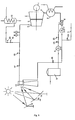
FIG. 1 is a schematic diagram of a solar and external steam hybrid power generation system according to Example 1 of the invention, in which, an overhead solar boiler matching heliostats directly supplies steam for a turboset; -
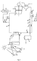
FIG. 2 is a schematic diagram of a solar and external steam hybrid power generation system according to Example 2 of the invention, in which, an overhead solar boiler matching heliostats indirectly supplies steam for a turboset through heat exchange; -
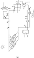
FIG. 3 is a schematic diagram of a solar and external steam hybrid power generation system according to Example 3 of the invention, in which, solar vacuum heat pipes matching trough type parabolic reflectors directly supplies steam for a turboset; and -
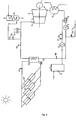
FIG. 4 is a schematic diagram of a solar and external steam hybrid power generation system according to Example 4 of the invention, in which, solar vacuum heat pipes matching trough type parabolic reflectors indirectly supplies steam for a turboset through heat exchange. - For further illustrating the invention, experiments detailing a solar and external steam hybrid power generation system are described below. It should be noted that the following examples are intended to describe and not to limit the invention.
- As shown in
FIG. 1 , a solar and external steam hybrid power generation system primarily comprises: a solar steam generator, anexternal steam regulator 15, aturboset 2, and a power generator 1 coupled to theturboset 2, acondenser 5, adeaerator 6, a water feed pump 7, a softwater storage tank 9, and awater supply pump 8, which are assembled by pipes and valves. The valves comprise a first switch valve16, a second switch valve19, a third switch valve21, a fourth switch valve23, and a fifth switch valve17 for controlling connection and disconnection of the pipes, and a first regulating valve18, a second regulating valve20, and a third regulating valve22for regulating the flow rate in the pipes. - The solar steam generator further comprises an overhead
solar boiler 13 and a plurality ofheliostats 14 matching therewith. Theheliostats 14 are capable of tracing the sun to enable the sunlight to always concentrate on a heat pipe of the overheadsolar boiler 13. An output end of the heat pipe of the overheadsolar boiler 13 is connected to a highpressure steam inlet 3 of theturboset 2 via thefifth switch valve 17 and thefirst regulating valve 18. A steam outlet end of theexternal steam regulator 15 is also connected to the highpressure steam inlet 3 of theturboset 2 via thesecond regulating valve 20 and thesecond switch valve 19. A second pipe close to the highpressure steam inlet 3 of theturboset 2 is provided with a pressure manometer P and a thermometer T for directly displaying pressure and temperature parameters of the steam. - A low pressure steam outlet 4 of the
turboset 2 is connected to an input end of thecondenser 5, and an output end of thecondenser 5 is connected to an input end of thedeaerator 6. A water outlet of the softwater storage tank 9 is connected a water inlet of thedeaerator 6 via awater supply pump 8. Thethird regulating valve 22 and thethird switch valve 21 are disposed on a first pipe connecting the water outlet of the softwater storage tank 9 and the water inlet of thedeaerator 6 for controlling the open and close of a water supply pipe and the volume of the supplying water. An output end of thedeaerator 6 is connected to an input end of the water feed pump 7; and an output end of the water feed pump 7 is connected to an input end of the heat pipe of the overheadsolar boiler 13 via thefirst switch valve 16, thereby forming a circulation loop of the solar steam generator. The output end of the water feed pump 7 is further connected to a water-return bypass11 of the external steam via thefourth switch valve 23, thereby forming a circulation loop for the work of the external steam. - Working process of the solar and external steam hybrid power generation system of Example 1 is as follows: in daytimes when the sunlight is abundant, the
second switch valve 19 and thefourth switch valve 23 are close, thefirst switch valve 16, thethird switch valve 21, and thefifth switch valve 17 are open, and the system runs at a concentrating solar thermal power generation state. At the time, theheliostats 14 trace the sunlight and concentrate the thermal energy of the sunlight on the heat pipe of the overheadsolar boiler 13 to heat the circulating water therein to form a high temperature and high pressure steam. The high temperature and high pressure steam is output from the heat pipe of the overheadsolar boiler 13, regulated by thefirst regulating valve 18 to reach a rated pressure and a rated temperature, and transported to theturboset 2 to do work for generating power. Steam after doing work is cooled by thecondenser 5 to form normal pressure and low temperature water at approximately 40°C which is transported to the deaerator 6for removal of the dissolved oxygen and then transported back to the heat pipe of the overheadsolar boiler 13 via the water feed pump 7 for a next circulation. Meanwhile, surface water or well water is collected, preliminarily purified, treated by a chemical water treatment plant for removing calcium and magnesium ions therein, and transported and stored in the softwater storage tank 9. When water is required to be supplied, soft water is sucked by thewater supply pump 8, a flow rate of the water is then regulated by thethird regulating valve 22, and the soft water is transported to thedeaerator 6 for supplementing the water loss. - At night or in rainy and cloudy days, the
first switch valve 16, thethird switch valve 21, and thefifth valve 17 are close, thefirst regulating valve 18 and the third regulating valve 22stay at zero positions, thesecond switch valve 19 and thefourth switch valve 23 are open, and the system runs at the external steam power generation state. An external waste steam is introduced to theexternal steam regulator 15 for decreasing pressure and temperature or increasing pressure and temperature according to practical working condition of the waste steam, then fine regulated by the second regulating valve to reach the rated pressure and rated temperature, and transported to theturboset 2 to do work. The steam after doing work is cooled by thecondenser 5 to form normal pressure and low temperature water at approximately 40°C which is transported to the deaerator 6for removal of the dissolved oxygen and then transported back to the external waste steam source via the water feed pump 7 and the water-return bypass11 of the external steam or transported and stored in the softwater storage tank 9. - As shown in
FIG. 2 , a solar and external steam hybrid power generation system primarily comprises: a solar steam generator, anexternal steam regulator 15, aturboset 2, and a power generator 1 coupled to theturboset 2, acondenser 5, adeaerator 6, a water feed pump 7, a softwater storage tank 9, and awater supply pump 8, which are assembled by pipes and valves. The valves comprise afirst switch valve 16, asecond switch valve 19, athird switch valve 21, afourth switch valve 23, and afifth switch valve 17 for controlling connection and disconnection of the pipes, and afirst regulating valve 18, asecond regulating valve 20, and athird regulating valve 22 for regulating the flow rate in the pipes. - The solar steam generator further comprises an overhead
solar boiler 13 and a plurality ofheliostats 14 matching therewith. Theheliostats 14 are capable of tracing the sun to enable the sunlight to always concentrate on a heat pipe of the overheadsolar boiler 13. An output end of a heat pipe of the overheadsolar boiler 13 is connected to a thermal medium inlet of aregenerative heat exchanger 12 via thefifth switch valve 17, and a thermal medium outlet of theregenerative heat exchanger 12 is connected to an input end of the heat pipe of the overheadsolar boiler 13 via aheat pump 10. The thermal medium is a mixed solution comprising biphenyl and diphenyl oxide filled in theregenerative heat exchanger 12 provided with a heat insulation layer. When the thermal medium absorbs heat, a temperature thereof increases to approximately 400°C, which is enough to be used for heat exchange to produce high temperature and high pressure steam. A steam outlet of theregenerative heat exchanger 12 is connected to the highpressure steam inlet 3 of theturboset 2 via thefirst regulating valve 18. A steam outlet end of theexternal steam regulator 15 is also connected to the highpressure steam inlet 3 of theturboset 2 via thesecond regulating valve 20 and thesecond switch valve 19. A second pipe close to the highpressure steam inlet 3 of theturboset 2 is provided with a pressure manometer P and a thermometer T for directly displaying pressure and temperature parameters of the steam. - A low pressure steam outlet 4 of the
turboset 2 is connected to an input end of thecondenser 5, and an output end of thecondenser 5 is connected to an input end of thedeaerator 6. A water outlet of the softwater storage tank 9 is connected a water inlet of thedeaerator 6 via awater supply pump 8. Thethird regulating valve 22 and thethird switch valve 21 are disposed on a first pipe connecting the water outlet of the softwater storage tank 9 and the water inlet of thedeaerator 6 for controlling the open and close of a water supply pipe and the volume of the supplying water. An output end of thedeaerator 6 is connected to an input end of the water feed pump 7; and an output end of the water feed pump 7 is connected to a circulating water inlet of the regenerative heat exchanger 12via thefirst switch valve 16, thereby forming a circulation loop of the solar steam generator. The output end of the water feed pump 7 is further connected to a water-return bypass11 of the external steam via thefourth switch valve 23, thereby forming a circulation loop for the work of the external steam. - Working process of the solar and external steam hybrid power generation system of Example 2 is as follows: in daytimes when the sunlight is abundant, the
second switch valve 19 and thefourth switch valve 23 are close, thefirst switch valve 16, thethird switch valve 21, and thefifth switch valve 17 are open, and the system runs at a concentrating solar thermal power generation state. At the time, theheliostats 14 trace the sunlight and concentrate the thermal energy of the sunlight on the heat pipe of the overheadsolar boiler 13 to enable the thermal medium therein, the mixed solution comprising biphenyl and diphenyl oxide, to absorb heat. The mixed solution comprising biphenyl and diphenyl oxide heated to approximately 400°C flows to theregenerative heat exchanger 12 via thefifth switch valve 17 and exchanges heat with the circulating water in another pipe of theregenerative heat exchanger 12. Thus, the temperature of the mixed solution comprising biphenyl and diphenyl oxide gradually decreases, approximately 245°C after flowing out of theregenerative heat exchanger 12. The mixed solution comprising biphenyl and diphenyl oxide is transported back to the heat pipe of the overhead solar boiler 13by the drive of theheat pump 10, for a next circulation of solar energy absorption. The circulating water in theregenerative heat exchanger 12 is transformed into the high temperature and high pressure steam after the heat exchange with the high temperature mixed solution comprising biphenyl and diphenyl oxide. The high temperature and high pressure steam is output from theregenerative heat exchanger 12, regulated by thefirst regulating valve 18 to reach a rated pressure and a rated temperature, and then transported to theturboset 2 to do work. Steam after doing work is cooled by thecondenser 5 to form normal pressure and low temperature water at approximately 40°C which is transported to the deaerator 6for removal of the dissolved oxygen and then transported back to the regenerative heat exchanger 12for heat exchange via the water feed pump 7, thereby forming high temperature and high pressure steam again. Meanwhile, surface water or well water is collected, preliminarily purified, treated by chemical water treatment plant for removing calcium and magnesium ions therein, and transported and stored in the softwater storage tank 9. When water is required to be supplied, soft water is sucked by thewater supply pump 8, a flow rate of the soft water is then regulated by thethird regulating valve 22, and the soft water is transported to thedeaerator 6 for supplementing the water loss. - At night or in rainy and cloudy days, the
first switch valve 16, thethird switch valve 21, and thefifth valve 17 are close, thefirst regulating valve 18 and the third regulating valve 22stay at zero positions, thesecond switch valve 19 and thefourth switch valve 23 are open, and the system runs at the external steam power generation state. An external waste steam is introduced to theexternal steam regulator 15 for decreasing pressure and temperature or increasing pressure and temperature according to practical working condition of the waste steam, then fine regulated by the second regulating valve to reach the rated pressure and rated temperature, and transported to theturboset 2 to do work. The steam after doing work is cooled by thecondenser 5 to form normal pressure and low temperature water at approximately 40°C which is transported to the deaerator 6for removal of the dissolved oxygen and then transported back to the external waste steam source via the water feed pump 7 and the water-return bypass11 of the external steam or transported and stored in the softwater storage tank 9. - As shown in
FIG. 3 , a structure of a solar and external steam hybrid power generation system is basically the same as that shown inFIG. 1 except for some slight variations that the solar steam generator comprises a plurality of solar vacuum heat pipes 13'and a plurality of trough type parabolic reflectors14' matching therewith. Output ends of the solar vacuum heat pipes 13'are connected to the highpressure steam inlet 3 of theturboset 2 via thefifth switch valve 17 and thefirst regulating valve 18. Input ends of the solar vacuum heat pipes 13'are connected to the output end of the water feed pump 7 via thefirst switch valve 16. Working processes of the two solar and external steam hybrid power generation systems are basically the same, so that it will not be repeatedly illustrated herein. - As shown in
FIG. 4 , a structure of a solar and external steam hybrid power generation system is basically the same as that shown inFIG. 2 except for some slight variations that the solar steam generator comprises a plurality of solar vacuum heat pipes 13'and a plurality of trough type parabolic reflectors14' matching therewith. Output ends of solar vacuum heat pipes 13'are connected to a thermal medium inlet of aregenerative heat exchanger 12 via afifth switch valve 17. A thermal medium outlet of theregenerative heat exchanger 12 is connected to input ends of the solar vacuum heat pipes 13'via aheat pump 10. A steam outlet of theregenerative heat exchanger 12 is connected to the highpressure steam inlet 3 of theturboset 2 via thefirst regulating valve 18. A circulating water inlet of the regenerative heat exchanger12 is connected to the output end of the water feed pump 7 via the first switch valve16. Working processes of the two solar and external steam hybrid power generation systems are basically the same, so that it will not be repeatedly illustrated herein.
Claims (7)
- A solar and external steam hybrid power generation system, comprising a solar steam generator, an external steam regulator (15), a turboset (2), and a power generator (1) coupled to the turboset (2), characterized in that a steam outlet end of the solar steam generator is connected to a high pressure steam inlet (3) of the turboset (2) via a first regulating valve (18); a steam outlet end of the external steam regulator (15) is also connected to the high pressure steam inlet (3) of the turboset (2) via a second regulating valve (20) and a second switch valve (19); a low pressure steam outlet (4) of the turboset (2) is connected to an input end of a condenser (5), and an output end of the condenser (5) is connected to an input end of a deaerator (6); an output end of the deaerator (6) is connected to an input end of a water feed pump (7); an output end of the water feed pump (7) is connected to a circulating water input end of the solar steam generator via a first switch valve (16); and the output end of the water feed pump (7) is further connected to a water-return bypass (11) of the external steam via a fourth switch valve (23).
- The system of claim 1, characterized in that the system further comprises a soft water storage tank (9), a water outlet of the soft water storage tank (9) is connected a water inlet of the deaerator (6) via a water supply pump (8), and a first pipe connecting the water outlet of the soft water storage tank (9) and the water inlet of the deaerator (6) is provided with a third regulating valve (22) and a third switch valve (21).
- The system of claim 2, characterized in that a second pipe close to the high pressure steam inlet (3) of the turboset (2) is provided with a pressure manometer (P) and a thermometer (T).
- The system of claim 1, 2, or 3, characterized in that the solar steam generator comprises an overhead solar boiler (13) and a plurality of heliostats (14) matching therewith; an output end of a heat pipe of the overhead solar boiler (13) is connected to the high pressure steam inlet (3) of the turboset (2) via the first regulating valve (18); and an input end of the heat pipe of the overhead solar boiler (13) is connected to the output end of the water feed pump (7) via the first switch valve (16).
- The system of claim 1, 2, or 3, characterized in that the solar steam generator comprises an overhead solar boiler (13) and a plurality of heliostats (14) matching therewith; an output end of a heat pipe of the overhead solar boiler (13) is connected to a thermal medium inlet of a regenerative heat exchanger (12) via a fifth switch valve (17), and a thermal medium outlet of the regenerative heat exchanger (12) is connected to an input end of the heat pipe of the overhead solar boiler (13) via a heat pump (10); a steam outlet of the regenerative heat exchanger (12) is connected to the high pressure steam inlet (3) of the turboset (2) via the first regulating valve (18); and a circulating water inlet of the regenerative heat exchanger (12) is connected to the output end of the water feed pump (7) via the first switch valve (16).
- The system of claim 1, 2, or 3, characterized in that the solar steam generator comprises a plurality of solar vacuum heat pipes (13') and a plurality of trough type parabolic reflectors (14') matching therewith; output ends of the solar vacuum heat pipes (13') are connected to the high pressure steam inlet (3) of the turboset (2) via the first regulating valve (18); and input ends of the solar vacuum heat pipes (13') are connected to the output end of the water feed pump (7) via the first switch valve (16).
- The system of claim 1, 2, or 3, characterized in that the solar steam generator comprises a plurality of solar vacuum heat pipes (13') and a plurality of trough type parabolic reflectors (14') matching therewith; output ends of solar vacuum heat pipes (13') are connected to a thermal medium inlet of a regenerative heat exchanger (12) via a fifth switch valve (17), and a thermal medium outlet of the regenerative heat exchanger (12) is connected to input ends of the solar vacuum heat pipes (13') via a heat pump (10); a steam outlet of the regenerative heat exchanger (12) is connected to the high pressure steam inlet (3) of the turboset (2) via the first regulating valve (18); and a circulating water inlet of the regenerative heat exchanger (12) is connected to the output end of the water feed pump (7) via the first switch valve (16).
Priority Applications (2)
| Application Number | Priority Date | Filing Date | Title |
|---|---|---|---|
| SI201231159T SI2801723T1 (en) | 2011-12-12 | 2012-10-18 | A device for simultaneous production of solar energy and steam from an external source |
| HRP20171933TT HRP20171933T1 (en) | 2011-12-12 | 2012-10-18 | Solar energy and external source steam complementary power generation apparatus |
Applications Claiming Priority (3)
| Application Number | Priority Date | Filing Date | Title |
|---|---|---|---|
| CN 201120515674 CN202326050U (en) | 2011-12-12 | 2011-12-12 | Solar energy and external source steam complementary power generation equipment |
| CN2011104119798A CN102418679B (en) | 2011-12-12 | 2011-12-12 | Solar energy and exogenous steam complementary power generation equipment |
| PCT/CN2012/083116 WO2013086895A1 (en) | 2011-12-12 | 2012-10-18 | Solar energy and external source steam complementary power generation apparatus |
Publications (3)
| Publication Number | Publication Date |
|---|---|
| EP2801723A1 EP2801723A1 (en) | 2014-11-12 |
| EP2801723A4 EP2801723A4 (en) | 2015-11-18 |
| EP2801723B1 true EP2801723B1 (en) | 2017-09-20 |
Family
ID=48611845
Family Applications (1)
| Application Number | Title | Priority Date | Filing Date |
|---|---|---|---|
| EP12858668.2A Not-in-force EP2801723B1 (en) | 2011-12-12 | 2012-10-18 | Solar energy and external source steam complementary power generation apparatus |
Country Status (17)
| Country | Link |
|---|---|
| US (1) | US9841008B2 (en) |
| EP (1) | EP2801723B1 (en) |
| JP (1) | JP5919390B2 (en) |
| KR (1) | KR101561978B1 (en) |
| AP (1) | AP4020A (en) |
| AU (1) | AU2012350645B2 (en) |
| BR (1) | BR112014014312A8 (en) |
| CA (1) | CA2860836A1 (en) |
| DK (1) | DK2801723T3 (en) |
| HR (1) | HRP20171933T1 (en) |
| LT (1) | LT2801723T (en) |
| MX (1) | MX345149B (en) |
| RU (1) | RU2602708C2 (en) |
| SG (1) | SG11201403128QA (en) |
| SI (1) | SI2801723T1 (en) |
| WO (1) | WO2013086895A1 (en) |
| ZA (1) | ZA201405001B (en) |
Cited By (2)
| Publication number | Priority date | Publication date | Assignee | Title |
|---|---|---|---|---|
| CN109209530A (en) * | 2018-08-31 | 2019-01-15 | 上海应用技术大学 | A kind of biomass power generation system that the distribution of modularization movable type is provided multiple forms of energy to complement each other |
| CN110566920A (en) * | 2019-09-12 | 2019-12-13 | 哈尔滨锅炉厂有限责任公司 | Groove tower combines steam generation system |
Families Citing this family (2)
| Publication number | Priority date | Publication date | Assignee | Title |
|---|---|---|---|---|
| CN104089407B (en) * | 2014-07-02 | 2015-09-16 | 浙江大学 | Based on the distributed multiple-supplying device and method of solar energy auxiliary gas turbine |
| US12421829B2 (en) * | 2021-09-21 | 2025-09-23 | Saudi Arabian Oil Company | Combined carbon dioxide disposal and freshwater production from a saline aquifer |
Family Cites Families (17)
| Publication number | Priority date | Publication date | Assignee | Title |
|---|---|---|---|---|
| US3953966A (en) * | 1974-08-08 | 1976-05-04 | Westinghouse Electric Corporation | Combined cycle electric power plant having a control system which enables dry steam generator operation during gas turbine operation |
| RU2032082C1 (en) * | 1990-02-23 | 1995-03-27 | Товарищество с ограниченной ответственностью "Ди Си Ди" | Modular solar-electric plant |
| DE19723543C2 (en) * | 1997-06-05 | 2003-04-17 | Deutsch Zentr Luft & Raumfahrt | Power generation plant |
| US7296410B2 (en) * | 2003-12-10 | 2007-11-20 | United Technologies Corporation | Solar power system and method for power generation |
| RU2282053C2 (en) * | 2004-04-28 | 2006-08-20 | Дагестанский государственный университет | Combination extraction power station |
| ES2327991B1 (en) * | 2006-08-04 | 2010-07-15 | Abengoa Solar New Technologies, S.A. | SOLAR CONCENTRATION PLANT. |
| JP4786504B2 (en) * | 2006-11-10 | 2011-10-05 | 川崎重工業株式会社 | Heat medium supply facility, solar combined power generation facility, and control method thereof |
| US8607567B2 (en) * | 2008-04-16 | 2013-12-17 | Alstom Technology Ltd | Solar steam generator |
| BRPI0919160A2 (en) * | 2008-09-17 | 2017-02-07 | Siemens Concentrated Solar Power Ltd | solar thermal power plant |
| WO2011033140A1 (en) * | 2009-09-18 | 2011-03-24 | Niazi Dehbagher Zargham | Device for generating electric power |
| CH702906A1 (en) | 2010-03-26 | 2011-09-30 | Alstom Technology Ltd | Method for operating an integrated solar combined cycle power plant and solar combined cycle power plant for implementing the process. |
| CN201786577U (en) * | 2010-08-09 | 2011-04-06 | 国电联合动力技术有限公司 | Natural air-cooling system of offshore wind generating set |
| CN201786587U (en) * | 2010-09-29 | 2011-04-06 | 武汉凯迪工程技术研究总院有限公司 | Solar energy power generation system adopting biomass boiler as auxiliary heat source |
| CN201827035U (en) * | 2010-10-29 | 2011-05-11 | 国电科技环保集团山东龙源环保有限公司 | Generating system with biomass boiler and solar boiler running in parallel |
| AT510279B1 (en) * | 2011-02-22 | 2012-03-15 | Klaus Dipl Ing Engelhart | METHOD FOR CONVERTING ENERGY |
| CN202326050U (en) * | 2011-12-12 | 2012-07-11 | 武汉凯迪工程技术研究总院有限公司 | Solar energy and external source steam complementary power generation equipment |
| CN102418679B (en) * | 2011-12-12 | 2013-11-13 | 武汉凯迪工程技术研究总院有限公司 | Solar energy and exogenous steam complementary power generation equipment |
-
2012
- 2012-10-18 MX MX2014006972A patent/MX345149B/en active IP Right Grant
- 2012-10-18 KR KR1020147016364A patent/KR101561978B1/en not_active Expired - Fee Related
- 2012-10-18 WO PCT/CN2012/083116 patent/WO2013086895A1/en not_active Ceased
- 2012-10-18 AU AU2012350645A patent/AU2012350645B2/en not_active Ceased
- 2012-10-18 AP AP2014007777A patent/AP4020A/en active
- 2012-10-18 SG SG11201403128QA patent/SG11201403128QA/en unknown
- 2012-10-18 JP JP2014546290A patent/JP5919390B2/en not_active Expired - Fee Related
- 2012-10-18 SI SI201231159T patent/SI2801723T1/en unknown
- 2012-10-18 CA CA2860836A patent/CA2860836A1/en not_active Abandoned
- 2012-10-18 BR BR112014014312A patent/BR112014014312A8/en not_active IP Right Cessation
- 2012-10-18 DK DK12858668.2T patent/DK2801723T3/en active
- 2012-10-18 HR HRP20171933TT patent/HRP20171933T1/en unknown
- 2012-10-18 EP EP12858668.2A patent/EP2801723B1/en not_active Not-in-force
- 2012-10-18 RU RU2015109761/06A patent/RU2602708C2/en not_active IP Right Cessation
- 2012-10-18 LT LTEP12858668.2T patent/LT2801723T/en unknown
-
2014
- 2014-06-11 US US14/302,419 patent/US9841008B2/en not_active Expired - Fee Related
- 2014-07-09 ZA ZA2014/05001A patent/ZA201405001B/en unknown
Non-Patent Citations (1)
| Title |
|---|
| None * |
Cited By (2)
| Publication number | Priority date | Publication date | Assignee | Title |
|---|---|---|---|---|
| CN109209530A (en) * | 2018-08-31 | 2019-01-15 | 上海应用技术大学 | A kind of biomass power generation system that the distribution of modularization movable type is provided multiple forms of energy to complement each other |
| CN110566920A (en) * | 2019-09-12 | 2019-12-13 | 哈尔滨锅炉厂有限责任公司 | Groove tower combines steam generation system |
Also Published As
| Publication number | Publication date |
|---|---|
| ZA201405001B (en) | 2015-11-25 |
| RU2015109761A (en) | 2016-10-10 |
| AP2014007777A0 (en) | 2014-07-31 |
| MX2014006972A (en) | 2014-10-17 |
| JP2015501904A (en) | 2015-01-19 |
| US20140290246A1 (en) | 2014-10-02 |
| KR20140079874A (en) | 2014-06-27 |
| HRP20171933T1 (en) | 2018-02-09 |
| US9841008B2 (en) | 2017-12-12 |
| JP5919390B2 (en) | 2016-05-18 |
| CA2860836A1 (en) | 2013-06-20 |
| BR112014014312A8 (en) | 2021-03-09 |
| SI2801723T1 (en) | 2018-04-30 |
| AU2012350645A1 (en) | 2014-07-03 |
| MX345149B (en) | 2017-01-18 |
| EP2801723A1 (en) | 2014-11-12 |
| BR112014014312A2 (en) | 2017-06-13 |
| AP4020A (en) | 2017-01-29 |
| AU2012350645B2 (en) | 2016-05-19 |
| DK2801723T3 (en) | 2018-01-08 |
| LT2801723T (en) | 2018-01-25 |
| KR101561978B1 (en) | 2015-10-20 |
| SG11201403128QA (en) | 2014-09-26 |
| RU2602708C2 (en) | 2016-11-20 |
| WO2013086895A1 (en) | 2013-06-20 |
| EP2801723A4 (en) | 2015-11-18 |
Similar Documents
| Publication | Publication Date | Title |
|---|---|---|
| RU2599697C1 (en) | Complementary heat energy system using solar energy and biomass | |
| CN204358978U (en) | A kind of energy storage type clean energy resource steam boiler adopting heat-conducting oil | |
| CN104145420B (en) | Renewable Energy Power Generation System | |
| CN102418679B (en) | Solar energy and exogenous steam complementary power generation equipment | |
| CN106523155B (en) | A kind of chemical formula recycle-water method and apparatus based on solar gas expander system | |
| AU2012350645B2 (en) | Solar energy and external source steam complementary power generation apparatus | |
| CN213295524U (en) | Circulating water comprehensive heat treatment system of hydrogen production device | |
| CN116658908A (en) | Power consumption system of waste incineration power plant based on heat storage of incineration fly ash and regenerated salt | |
| CN214625114U (en) | Liquid hydrogen fuel cell waste heat recovery system | |
| CN202326049U (en) | Solar energy and methane energy complementary power generation equipment | |
| CN115013096A (en) | A thermal power generation, photothermal and supercritical carbon dioxide coupled power generation system and method | |
| CN102493931A (en) | Solar energy and methane energy complementation-based electricity generating equipment | |
| CN106225541A (en) | The tower solar-thermal generating system of the many heat collectors of single column formula | |
| Alqatamin et al. | Hybrid PVT-PVSFs powered desalination system with phase change material thermal energy storage: Dynamic simulation in an actual weather condition for sustainable off-grid freshwater production | |
| CN103896350B (en) | A kind of island seawater desalination system and method | |
| CN112097228B (en) | Steam generation system for solar photo-thermal power station and operation method thereof | |
| CN204851350U (en) | Utilize living water heating system of power plant's exhaust steam waste heat | |
| CN202326050U (en) | Solar energy and external source steam complementary power generation equipment | |
| CN217843807U (en) | Aqueous medium energy storage power generation steam supply system | |
| CN114105240B (en) | A solar distillation seawater desalination system | |
| CN212319668U (en) | Steam generation system for solar photo-thermal power station | |
| CN113530773B (en) | Power generation system and method of operating the same | |
| CN102701305B (en) | Light-condensing and heat-collecting multistage flash evaporation process device based on feedback control | |
| CN203605494U (en) | Wind energy and solar energy power generation and hot water supply comprehensive utilization system | |
| CN220931213U (en) | Photo-thermal heat supply and heat storage device and steam system |
Legal Events
| Date | Code | Title | Description |
|---|---|---|---|
| PUAI | Public reference made under article 153(3) epc to a published international application that has entered the european phase |
Free format text: ORIGINAL CODE: 0009012 |
|
| 17P | Request for examination filed |
Effective date: 20140714 |
|
| AK | Designated contracting states |
Kind code of ref document: A1 Designated state(s): AL AT BE BG CH CY CZ DE DK EE ES FI FR GB GR HR HU IE IS IT LI LT LU LV MC MK MT NL NO PL PT RO RS SE SI SK SM TR |
|
| DAX | Request for extension of the european patent (deleted) | ||
| RA4 | Supplementary search report drawn up and despatched (corrected) |
Effective date: 20151020 |
|
| RIC1 | Information provided on ipc code assigned before grant |
Ipc: F01K 11/02 20060101ALI20151014BHEP Ipc: F03G 6/06 20060101AFI20151014BHEP |
|
| GRAP | Despatch of communication of intention to grant a patent |
Free format text: ORIGINAL CODE: EPIDOSNIGR1 |
|
| STAA | Information on the status of an ep patent application or granted ep patent |
Free format text: STATUS: GRANT OF PATENT IS INTENDED |
|
| INTG | Intention to grant announced |
Effective date: 20170420 |
|
| RAP1 | Party data changed (applicant data changed or rights of an application transferred) |
Owner name: WUHAN KAIDI ENGINEERING TECHNOLOGY RESEARCH INSTIT |
|
| GRAS | Grant fee paid |
Free format text: ORIGINAL CODE: EPIDOSNIGR3 |
|
| GRAA | (expected) grant |
Free format text: ORIGINAL CODE: 0009210 |
|
| STAA | Information on the status of an ep patent application or granted ep patent |
Free format text: STATUS: THE PATENT HAS BEEN GRANTED |
|
| AK | Designated contracting states |
Kind code of ref document: B1 Designated state(s): AL AT BE BG CH CY CZ DE DK EE ES FI FR GB GR HR HU IE IS IT LI LT LU LV MC MK MT NL NO PL PT RO RS SE SI SK SM TR |
|
| REG | Reference to a national code |
Ref country code: GB Ref legal event code: FG4D |
|
| REG | Reference to a national code |
Ref country code: CH Ref legal event code: EP |
|
| REG | Reference to a national code |
Ref country code: AT Ref legal event code: REF Ref document number: 930376 Country of ref document: AT Kind code of ref document: T Effective date: 20171015 |
|
| REG | Reference to a national code |
Ref country code: IE Ref legal event code: FG4D |
|
| REG | Reference to a national code |
Ref country code: FR Ref legal event code: PLFP Year of fee payment: 6 |
|
| REG | Reference to a national code |
Ref country code: DE Ref legal event code: R096 Ref document number: 602012037663 Country of ref document: DE |
|
| REG | Reference to a national code |
Ref country code: HR Ref legal event code: TUEP Ref document number: P20171933 Country of ref document: HR |
|
| REG | Reference to a national code |
Ref country code: CH Ref legal event code: NV Representative=s name: RENTSCH PARTNER AG, CH |
|
| REG | Reference to a national code |
Ref country code: DK Ref legal event code: T3 Effective date: 20180103 |
|
| REG | Reference to a national code |
Ref country code: NL Ref legal event code: FP |
|
| REG | Reference to a national code |
Ref country code: SE Ref legal event code: TRGR |
|
| PG25 | Lapsed in a contracting state [announced via postgrant information from national office to epo] |
Ref country code: NO Free format text: LAPSE BECAUSE OF FAILURE TO SUBMIT A TRANSLATION OF THE DESCRIPTION OR TO PAY THE FEE WITHIN THE PRESCRIBED TIME-LIMIT Effective date: 20171220 |
|
| REG | Reference to a national code |
Ref country code: HR Ref legal event code: T1PR Ref document number: P20171933 Country of ref document: HR |
|
| REG | Reference to a national code |
Ref country code: AT Ref legal event code: MK05 Ref document number: 930376 Country of ref document: AT Kind code of ref document: T Effective date: 20170920 |
|
| PG25 | Lapsed in a contracting state [announced via postgrant information from national office to epo] |
Ref country code: BG Free format text: LAPSE BECAUSE OF FAILURE TO SUBMIT A TRANSLATION OF THE DESCRIPTION OR TO PAY THE FEE WITHIN THE PRESCRIBED TIME-LIMIT Effective date: 20171220 Ref country code: RS Free format text: LAPSE BECAUSE OF FAILURE TO SUBMIT A TRANSLATION OF THE DESCRIPTION OR TO PAY THE FEE WITHIN THE PRESCRIBED TIME-LIMIT Effective date: 20170920 Ref country code: GR Free format text: LAPSE BECAUSE OF FAILURE TO SUBMIT A TRANSLATION OF THE DESCRIPTION OR TO PAY THE FEE WITHIN THE PRESCRIBED TIME-LIMIT Effective date: 20171221 |
|
| PG25 | Lapsed in a contracting state [announced via postgrant information from national office to epo] |
Ref country code: CZ Free format text: LAPSE BECAUSE OF FAILURE TO SUBMIT A TRANSLATION OF THE DESCRIPTION OR TO PAY THE FEE WITHIN THE PRESCRIBED TIME-LIMIT Effective date: 20170920 Ref country code: PL Free format text: LAPSE BECAUSE OF FAILURE TO SUBMIT A TRANSLATION OF THE DESCRIPTION OR TO PAY THE FEE WITHIN THE PRESCRIBED TIME-LIMIT Effective date: 20170920 Ref country code: ES Free format text: LAPSE BECAUSE OF FAILURE TO SUBMIT A TRANSLATION OF THE DESCRIPTION OR TO PAY THE FEE WITHIN THE PRESCRIBED TIME-LIMIT Effective date: 20170920 Ref country code: RO Free format text: LAPSE BECAUSE OF FAILURE TO SUBMIT A TRANSLATION OF THE DESCRIPTION OR TO PAY THE FEE WITHIN THE PRESCRIBED TIME-LIMIT Effective date: 20170920 |
|
| PG25 | Lapsed in a contracting state [announced via postgrant information from national office to epo] |
Ref country code: EE Free format text: LAPSE BECAUSE OF FAILURE TO SUBMIT A TRANSLATION OF THE DESCRIPTION OR TO PAY THE FEE WITHIN THE PRESCRIBED TIME-LIMIT Effective date: 20170920 Ref country code: SK Free format text: LAPSE BECAUSE OF FAILURE TO SUBMIT A TRANSLATION OF THE DESCRIPTION OR TO PAY THE FEE WITHIN THE PRESCRIBED TIME-LIMIT Effective date: 20170920 Ref country code: IS Free format text: LAPSE BECAUSE OF FAILURE TO SUBMIT A TRANSLATION OF THE DESCRIPTION OR TO PAY THE FEE WITHIN THE PRESCRIBED TIME-LIMIT Effective date: 20180120 Ref country code: AT Free format text: LAPSE BECAUSE OF FAILURE TO SUBMIT A TRANSLATION OF THE DESCRIPTION OR TO PAY THE FEE WITHIN THE PRESCRIBED TIME-LIMIT Effective date: 20170920 Ref country code: SM Free format text: LAPSE BECAUSE OF FAILURE TO SUBMIT A TRANSLATION OF THE DESCRIPTION OR TO PAY THE FEE WITHIN THE PRESCRIBED TIME-LIMIT Effective date: 20170920 Ref country code: IT Free format text: LAPSE BECAUSE OF FAILURE TO SUBMIT A TRANSLATION OF THE DESCRIPTION OR TO PAY THE FEE WITHIN THE PRESCRIBED TIME-LIMIT Effective date: 20170920 |
|
| REG | Reference to a national code |
Ref country code: DE Ref legal event code: R097 Ref document number: 602012037663 Country of ref document: DE |
|
| PLBE | No opposition filed within time limit |
Free format text: ORIGINAL CODE: 0009261 |
|
| STAA | Information on the status of an ep patent application or granted ep patent |
Free format text: STATUS: NO OPPOSITION FILED WITHIN TIME LIMIT |
|
| PG25 | Lapsed in a contracting state [announced via postgrant information from national office to epo] |
Ref country code: LU Free format text: LAPSE BECAUSE OF NON-PAYMENT OF DUE FEES Effective date: 20171018 |
|
| REG | Reference to a national code |
Ref country code: BE Ref legal event code: MM Effective date: 20171031 |
|
| 26N | No opposition filed |
Effective date: 20180621 |
|
| PG25 | Lapsed in a contracting state [announced via postgrant information from national office to epo] |
Ref country code: BE Free format text: LAPSE BECAUSE OF NON-PAYMENT OF DUE FEES Effective date: 20171031 |
|
| PG25 | Lapsed in a contracting state [announced via postgrant information from national office to epo] |
Ref country code: MT Free format text: LAPSE BECAUSE OF NON-PAYMENT OF DUE FEES Effective date: 20171018 |
|
| REG | Reference to a national code |
Ref country code: FR Ref legal event code: PLFP Year of fee payment: 7 |
|
| REG | Reference to a national code |
Ref country code: HR Ref legal event code: ODRP Ref document number: P20171933 Country of ref document: HR Payment date: 20181119 Year of fee payment: 7 |
|
| PGFP | Annual fee paid to national office [announced via postgrant information from national office to epo] |
Ref country code: NL Payment date: 20181030 Year of fee payment: 7 |
|
| PGFP | Annual fee paid to national office [announced via postgrant information from national office to epo] |
Ref country code: DE Payment date: 20181030 Year of fee payment: 7 Ref country code: FI Payment date: 20181029 Year of fee payment: 7 Ref country code: SE Payment date: 20181030 Year of fee payment: 7 Ref country code: MC Payment date: 20181031 Year of fee payment: 7 Ref country code: DK Payment date: 20181030 Year of fee payment: 7 Ref country code: IE Payment date: 20181030 Year of fee payment: 7 Ref country code: LT Payment date: 20181113 Year of fee payment: 7 |
|
| PGFP | Annual fee paid to national office [announced via postgrant information from national office to epo] |
Ref country code: GB Payment date: 20181030 Year of fee payment: 7 Ref country code: CH Payment date: 20181120 Year of fee payment: 7 Ref country code: FR Payment date: 20181030 Year of fee payment: 7 Ref country code: HR Payment date: 20181119 Year of fee payment: 7 Ref country code: LV Payment date: 20181030 Year of fee payment: 7 Ref country code: SI Payment date: 20181228 Year of fee payment: 7 |
|
| PG25 | Lapsed in a contracting state [announced via postgrant information from national office to epo] |
Ref country code: HU Free format text: LAPSE BECAUSE OF FAILURE TO SUBMIT A TRANSLATION OF THE DESCRIPTION OR TO PAY THE FEE WITHIN THE PRESCRIBED TIME-LIMIT; INVALID AB INITIO Effective date: 20121018 |
|
| PG25 | Lapsed in a contracting state [announced via postgrant information from national office to epo] |
Ref country code: CY Free format text: LAPSE BECAUSE OF FAILURE TO SUBMIT A TRANSLATION OF THE DESCRIPTION OR TO PAY THE FEE WITHIN THE PRESCRIBED TIME-LIMIT Effective date: 20170920 |
|
| PG25 | Lapsed in a contracting state [announced via postgrant information from national office to epo] |
Ref country code: MK Free format text: LAPSE BECAUSE OF FAILURE TO SUBMIT A TRANSLATION OF THE DESCRIPTION OR TO PAY THE FEE WITHIN THE PRESCRIBED TIME-LIMIT Effective date: 20170920 |
|
| PG25 | Lapsed in a contracting state [announced via postgrant information from national office to epo] |
Ref country code: TR Free format text: LAPSE BECAUSE OF FAILURE TO SUBMIT A TRANSLATION OF THE DESCRIPTION OR TO PAY THE FEE WITHIN THE PRESCRIBED TIME-LIMIT Effective date: 20170920 |
|
| REG | Reference to a national code |
Ref country code: HR Ref legal event code: PBON Ref document number: P20171933 Country of ref document: HR Effective date: 20191018 |
|
| REG | Reference to a national code |
Ref country code: DE Ref legal event code: R119 Ref document number: 602012037663 Country of ref document: DE |
|
| REG | Reference to a national code |
Ref country code: FI Ref legal event code: MAE |
|
| REG | Reference to a national code |
Ref country code: DK Ref legal event code: EBP Effective date: 20191031 |
|
| PG25 | Lapsed in a contracting state [announced via postgrant information from national office to epo] |
Ref country code: PT Free format text: LAPSE BECAUSE OF FAILURE TO SUBMIT A TRANSLATION OF THE DESCRIPTION OR TO PAY THE FEE WITHIN THE PRESCRIBED TIME-LIMIT Effective date: 20170920 Ref country code: MC Free format text: LAPSE BECAUSE OF NON-PAYMENT OF DUE FEES Effective date: 20191031 |
|
| REG | Reference to a national code |
Ref country code: CH Ref legal event code: PL |
|
| REG | Reference to a national code |
Ref country code: NL Ref legal event code: MM Effective date: 20191101 |
|
| REG | Reference to a national code |
Ref country code: LT Ref legal event code: MM4D Effective date: 20191018 |
|
| PG25 | Lapsed in a contracting state [announced via postgrant information from national office to epo] |
Ref country code: AL Free format text: LAPSE BECAUSE OF FAILURE TO SUBMIT A TRANSLATION OF THE DESCRIPTION OR TO PAY THE FEE WITHIN THE PRESCRIBED TIME-LIMIT Effective date: 20170920 Ref country code: FI Free format text: LAPSE BECAUSE OF NON-PAYMENT OF DUE FEES Effective date: 20191018 Ref country code: LI Free format text: LAPSE BECAUSE OF NON-PAYMENT OF DUE FEES Effective date: 20191031 Ref country code: CH Free format text: LAPSE BECAUSE OF NON-PAYMENT OF DUE FEES Effective date: 20191031 Ref country code: DE Free format text: LAPSE BECAUSE OF NON-PAYMENT OF DUE FEES Effective date: 20200501 |
|
| PG25 | Lapsed in a contracting state [announced via postgrant information from national office to epo] |
Ref country code: HR Free format text: LAPSE BECAUSE OF NON-PAYMENT OF DUE FEES Effective date: 20191018 Ref country code: LV Free format text: LAPSE BECAUSE OF NON-PAYMENT OF DUE FEES Effective date: 20191018 Ref country code: SE Free format text: LAPSE BECAUSE OF NON-PAYMENT OF DUE FEES Effective date: 20191019 Ref country code: NL Free format text: LAPSE BECAUSE OF NON-PAYMENT OF DUE FEES Effective date: 20191101 |
|
| GBPC | Gb: european patent ceased through non-payment of renewal fee |
Effective date: 20191018 |
|
| PG25 | Lapsed in a contracting state [announced via postgrant information from national office to epo] |
Ref country code: GB Free format text: LAPSE BECAUSE OF NON-PAYMENT OF DUE FEES Effective date: 20191018 Ref country code: DK Free format text: LAPSE BECAUSE OF NON-PAYMENT OF DUE FEES Effective date: 20191031 Ref country code: IE Free format text: LAPSE BECAUSE OF NON-PAYMENT OF DUE FEES Effective date: 20191018 Ref country code: FR Free format text: LAPSE BECAUSE OF NON-PAYMENT OF DUE FEES Effective date: 20191031 Ref country code: LT Free format text: LAPSE BECAUSE OF NON-PAYMENT OF DUE FEES Effective date: 20191018 |
|
| PG25 | Lapsed in a contracting state [announced via postgrant information from national office to epo] |
Ref country code: SI Free format text: LAPSE BECAUSE OF NON-PAYMENT OF DUE FEES Effective date: 20191019 |