EP2801492A2 - Vehicle heating/cooling system with consolidated heating/cooling core - Google Patents
Vehicle heating/cooling system with consolidated heating/cooling core Download PDFInfo
- Publication number
- EP2801492A2 EP2801492A2 EP20140165610 EP14165610A EP2801492A2 EP 2801492 A2 EP2801492 A2 EP 2801492A2 EP 20140165610 EP20140165610 EP 20140165610 EP 14165610 A EP14165610 A EP 14165610A EP 2801492 A2 EP2801492 A2 EP 2801492A2
- Authority
- EP
- European Patent Office
- Prior art keywords
- cylinder
- closed path
- closed
- heating
- thermally regulated
- Prior art date
- Legal status (The legal status is an assumption and is not a legal conclusion. Google has not performed a legal analysis and makes no representation as to the accuracy of the status listed.)
- Granted
Links
- 238000001816 cooling Methods 0.000 title claims abstract description 89
- 238000010438 heat treatment Methods 0.000 title claims abstract description 88
- 239000012530 fluid Substances 0.000 claims abstract description 96
- 230000001105 regulatory effect Effects 0.000 claims abstract description 73
- 239000003507 refrigerant Substances 0.000 claims abstract description 53
- 239000002826 coolant Substances 0.000 claims abstract description 43
- 238000002485 combustion reaction Methods 0.000 claims description 7
- 239000007788 liquid Substances 0.000 description 15
- 238000010586 diagram Methods 0.000 description 3
- 230000003750 conditioning effect Effects 0.000 description 2
- 239000012080 ambient air Substances 0.000 description 1
- 238000004519 manufacturing process Methods 0.000 description 1
- 238000009428 plumbing Methods 0.000 description 1
- 238000005057 refrigeration Methods 0.000 description 1
- 230000008016 vaporization Effects 0.000 description 1
Images

Classifications
-
- H—ELECTRICITY
- H01—ELECTRIC ELEMENTS
- H01M—PROCESSES OR MEANS, e.g. BATTERIES, FOR THE DIRECT CONVERSION OF CHEMICAL ENERGY INTO ELECTRICAL ENERGY
- H01M10/00—Secondary cells; Manufacture thereof
- H01M10/60—Heating or cooling; Temperature control
- H01M10/61—Types of temperature control
- H01M10/613—Cooling or keeping cold
-
- B—PERFORMING OPERATIONS; TRANSPORTING
- B60—VEHICLES IN GENERAL
- B60H—ARRANGEMENTS OF HEATING, COOLING, VENTILATING OR OTHER AIR-TREATING DEVICES SPECIALLY ADAPTED FOR PASSENGER OR GOODS SPACES OF VEHICLES
- B60H1/00—Heating, cooling or ventilating [HVAC] devices
-
- B—PERFORMING OPERATIONS; TRANSPORTING
- B60—VEHICLES IN GENERAL
- B60H—ARRANGEMENTS OF HEATING, COOLING, VENTILATING OR OTHER AIR-TREATING DEVICES SPECIALLY ADAPTED FOR PASSENGER OR GOODS SPACES OF VEHICLES
- B60H1/00—Heating, cooling or ventilating [HVAC] devices
- B60H1/00271—HVAC devices specially adapted for particular vehicle parts or components and being connected to the vehicle HVAC unit
- B60H1/00278—HVAC devices specially adapted for particular vehicle parts or components and being connected to the vehicle HVAC unit for the battery
-
- B—PERFORMING OPERATIONS; TRANSPORTING
- B60—VEHICLES IN GENERAL
- B60H—ARRANGEMENTS OF HEATING, COOLING, VENTILATING OR OTHER AIR-TREATING DEVICES SPECIALLY ADAPTED FOR PASSENGER OR GOODS SPACES OF VEHICLES
- B60H1/00—Heating, cooling or ventilating [HVAC] devices
- B60H1/00321—Heat exchangers for air-conditioning devices
- B60H1/00342—Heat exchangers for air-conditioning devices of the liquid-liquid type
-
- B—PERFORMING OPERATIONS; TRANSPORTING
- B60—VEHICLES IN GENERAL
- B60H—ARRANGEMENTS OF HEATING, COOLING, VENTILATING OR OTHER AIR-TREATING DEVICES SPECIALLY ADAPTED FOR PASSENGER OR GOODS SPACES OF VEHICLES
- B60H1/00—Heating, cooling or ventilating [HVAC] devices
- B60H1/00357—Air-conditioning arrangements specially adapted for particular vehicles
- B60H1/00385—Air-conditioning arrangements specially adapted for particular vehicles for vehicles having an electrical drive, e.g. hybrid or fuel cell
- B60H1/00392—Air-conditioning arrangements specially adapted for particular vehicles for vehicles having an electrical drive, e.g. hybrid or fuel cell for electric vehicles having only electric drive means
-
- B—PERFORMING OPERATIONS; TRANSPORTING
- B60—VEHICLES IN GENERAL
- B60H—ARRANGEMENTS OF HEATING, COOLING, VENTILATING OR OTHER AIR-TREATING DEVICES SPECIALLY ADAPTED FOR PASSENGER OR GOODS SPACES OF VEHICLES
- B60H1/00—Heating, cooling or ventilating [HVAC] devices
- B60H1/32—Cooling devices
- B60H1/3204—Cooling devices using compression
- B60H1/3228—Cooling devices using compression characterised by refrigerant circuit configurations
- B60H1/32281—Cooling devices using compression characterised by refrigerant circuit configurations comprising a single secondary circuit, e.g. at evaporator or condenser side
-
- F—MECHANICAL ENGINEERING; LIGHTING; HEATING; WEAPONS; BLASTING
- F01—MACHINES OR ENGINES IN GENERAL; ENGINE PLANTS IN GENERAL; STEAM ENGINES
- F01P—COOLING OF MACHINES OR ENGINES IN GENERAL; COOLING OF INTERNAL-COMBUSTION ENGINES
- F01P3/00—Liquid cooling
- F01P3/20—Cooling circuits not specific to a single part of engine or machine
-
- F—MECHANICAL ENGINEERING; LIGHTING; HEATING; WEAPONS; BLASTING
- F28—HEAT EXCHANGE IN GENERAL
- F28D—HEAT-EXCHANGE APPARATUS, NOT PROVIDED FOR IN ANOTHER SUBCLASS, IN WHICH THE HEAT-EXCHANGE MEDIA DO NOT COME INTO DIRECT CONTACT
- F28D7/00—Heat-exchange apparatus having stationary tubular conduit assemblies for both heat-exchange media, the media being in contact with different sides of a conduit wall
- F28D7/0066—Multi-circuit heat-exchangers, e.g. integrating different heat exchange sections in the same unit or heat-exchangers for more than two fluids
- F28D7/0083—Multi-circuit heat-exchangers, e.g. integrating different heat exchange sections in the same unit or heat-exchangers for more than two fluids with units having particular arrangement relative to a supplementary heat exchange medium, e.g. with interleaved units or with adjacent units arranged in common flow of supplementary heat exchange medium
-
- F—MECHANICAL ENGINEERING; LIGHTING; HEATING; WEAPONS; BLASTING
- F28—HEAT EXCHANGE IN GENERAL
- F28D—HEAT-EXCHANGE APPARATUS, NOT PROVIDED FOR IN ANOTHER SUBCLASS, IN WHICH THE HEAT-EXCHANGE MEDIA DO NOT COME INTO DIRECT CONTACT
- F28D7/00—Heat-exchange apparatus having stationary tubular conduit assemblies for both heat-exchange media, the media being in contact with different sides of a conduit wall
- F28D7/10—Heat-exchange apparatus having stationary tubular conduit assemblies for both heat-exchange media, the media being in contact with different sides of a conduit wall the conduits being arranged one within the other, e.g. concentrically
- F28D7/103—Heat-exchange apparatus having stationary tubular conduit assemblies for both heat-exchange media, the media being in contact with different sides of a conduit wall the conduits being arranged one within the other, e.g. concentrically consisting of more than two coaxial conduits or modules of more than two coaxial conduits
-
- F—MECHANICAL ENGINEERING; LIGHTING; HEATING; WEAPONS; BLASTING
- F28—HEAT EXCHANGE IN GENERAL
- F28D—HEAT-EXCHANGE APPARATUS, NOT PROVIDED FOR IN ANOTHER SUBCLASS, IN WHICH THE HEAT-EXCHANGE MEDIA DO NOT COME INTO DIRECT CONTACT
- F28D7/00—Heat-exchange apparatus having stationary tubular conduit assemblies for both heat-exchange media, the media being in contact with different sides of a conduit wall
- F28D7/10—Heat-exchange apparatus having stationary tubular conduit assemblies for both heat-exchange media, the media being in contact with different sides of a conduit wall the conduits being arranged one within the other, e.g. concentrically
- F28D7/106—Heat-exchange apparatus having stationary tubular conduit assemblies for both heat-exchange media, the media being in contact with different sides of a conduit wall the conduits being arranged one within the other, e.g. concentrically consisting of two coaxial conduits or modules of two coaxial conduits
-
- B—PERFORMING OPERATIONS; TRANSPORTING
- B60—VEHICLES IN GENERAL
- B60H—ARRANGEMENTS OF HEATING, COOLING, VENTILATING OR OTHER AIR-TREATING DEVICES SPECIALLY ADAPTED FOR PASSENGER OR GOODS SPACES OF VEHICLES
- B60H1/00—Heating, cooling or ventilating [HVAC] devices
- B60H1/00271—HVAC devices specially adapted for particular vehicle parts or components and being connected to the vehicle HVAC unit
- B60H2001/00307—Component temperature regulation using a liquid flow
-
- F—MECHANICAL ENGINEERING; LIGHTING; HEATING; WEAPONS; BLASTING
- F01—MACHINES OR ENGINES IN GENERAL; ENGINE PLANTS IN GENERAL; STEAM ENGINES
- F01P—COOLING OF MACHINES OR ENGINES IN GENERAL; COOLING OF INTERNAL-COMBUSTION ENGINES
- F01P2050/00—Applications
- F01P2050/24—Hybrid vehicles
-
- F—MECHANICAL ENGINEERING; LIGHTING; HEATING; WEAPONS; BLASTING
- F01—MACHINES OR ENGINES IN GENERAL; ENGINE PLANTS IN GENERAL; STEAM ENGINES
- F01P—COOLING OF MACHINES OR ENGINES IN GENERAL; COOLING OF INTERNAL-COMBUSTION ENGINES
- F01P2060/00—Cooling circuits using auxiliaries
- F01P2060/08—Cabin heater
-
- F—MECHANICAL ENGINEERING; LIGHTING; HEATING; WEAPONS; BLASTING
- F28—HEAT EXCHANGE IN GENERAL
- F28D—HEAT-EXCHANGE APPARATUS, NOT PROVIDED FOR IN ANOTHER SUBCLASS, IN WHICH THE HEAT-EXCHANGE MEDIA DO NOT COME INTO DIRECT CONTACT
- F28D21/00—Heat-exchange apparatus not covered by any of the groups F28D1/00 - F28D20/00
- F28D2021/0019—Other heat exchangers for particular applications; Heat exchange systems not otherwise provided for
- F28D2021/008—Other heat exchangers for particular applications; Heat exchange systems not otherwise provided for for vehicles
-
- Y—GENERAL TAGGING OF NEW TECHNOLOGICAL DEVELOPMENTS; GENERAL TAGGING OF CROSS-SECTIONAL TECHNOLOGIES SPANNING OVER SEVERAL SECTIONS OF THE IPC; TECHNICAL SUBJECTS COVERED BY FORMER USPC CROSS-REFERENCE ART COLLECTIONS [XRACs] AND DIGESTS
- Y02—TECHNOLOGIES OR APPLICATIONS FOR MITIGATION OR ADAPTATION AGAINST CLIMATE CHANGE
- Y02E—REDUCTION OF GREENHOUSE GAS [GHG] EMISSIONS, RELATED TO ENERGY GENERATION, TRANSMISSION OR DISTRIBUTION
- Y02E60/00—Enabling technologies; Technologies with a potential or indirect contribution to GHG emissions mitigation
- Y02E60/10—Energy storage using batteries
Definitions
- This invention relates to vehicle heating/cooling systems. More particularly, it relates to heat exchangers for vehicle heating/cooling systems. Even more particularly, it relates to consolidated heating/cooling cores for such heat exchangers.
- Vehicle heating/cooling systems typically employed separate heat exchangers for heating circuits and for cooling circuits. Providing the separate heat exchangers requires additional space and plumbing, including additional valves and conduits to direct the flow to the separate heat exchangers in the system.
- a vehicle heating/cooling system for a vehicle comprising an internal combustion engine coupled to a closed engine coolant circuit to recirculate engine coolant therethrough; a refrigerant compressor coupled to a closed refrigerant circuit to recirculate refrigerant therethrough, wherein the refrigerant compressor is coupled to the internal combustion engine to be driven thereby; a closed thermally regulated fluid circuit to recirculate thermally regulated fluid therethrough; and a consolidated heating/cooling core coupled to the closed engine coolant circuit, to the closed refrigerant circuit and to the closed thermally regulated fluid circuit.
- the consolidated heating/cooling core may define a first closed path for conducting the engine coolant therethrough, and the consolidated heating/cooling core may define a second closed path for conducting the refrigerant therethrough, and the consolidated heating/cooling core may define a third closed path for conducting the thermally regulated fluid therethrough.
- the first closed path, the second closed path and the third closed path may be defined by a plurality of cylinders.
- the plurality of cylinders may comprise a first cylinder, a second cylinder, and a third cylinder, and each cylinder of the plurality of cylinders may have an inner surface and an outer surface, and the first cylinder may be surrounded by the second cylinder which may be surrounded by the third cylinder.
- At least one of the first closed path and the second closed path may be defined by an inner surface of the first cylinder, and at least another of the first closed path and the second closed path may be defined by a space between the outer surface of the second cylinder and the inner surface of the third cylinder, and the third closed path may be defined by the space between the outer surface of the first cylinder and the inner surface of the second cylinder.
- the plurality of cylinders may comprise a first cylinder, a second cylinder, and a third cylinder and each cylinder of the plurality of cylinders may have an inner surface and an outer surface, and the first cylinder may be surrounded by the second cylinder and the third cylinder may be surrounded by the second cylinder.
- the first closed path may be defined by an inner surface of the first cylinder
- the second closed path may be defined by an inner surface of the third cylinder
- the third closed path may be defined by a space between the outer surface of the first cylinder and the inner surface of the second cylinder
- the third closed path may be defined by the space between the outer surface of the third cylinder and the inner surface of the second cylinder.
- the plurality of cylinders may be concentric.
- Each cylinder of the plurality of cylinders may be nested within at least another cylinder of the plurality of cylinders.
- the closed thermally regulated fluid circuit may pass through a thermally regulated load, and the thermally regulated load may comprise a battery.
- the closed thermally regulated fluid circuit may pass through a thermally regulated load, and further wherein the thermally regulated load comprises an inverter.
- the consolidated heating/cooling core may be a rigid, unitary body.
- a fluid flow direction through one of the first closed path, the second closed path and the third closed path may be opposite to a fluid flow direction through the other two of the first closed path, the second closed path and the third closed path.
- a consolidated heating/cooling core for a vehicle heating/cooling system comprising a closed engine coolant circuit for conducting engine coolant therethrough, a closed refrigerant circuit for conducting refrigerant therethrough, and a closed thermally regulated fluid circuit for conducting thermally regulated fluid therethrough, the consolidated heating/cooling core comprising: a first closed path for conducting the engine coolant therethrough; a second closed path for conducting the refrigerant therethrough; and a third closed path for conducting the thermally regulated fluid therethrough.
- the first closed path, the second closed path and the third closed path may be defined by a plurality of cylinders.
- the plurality of cylinders may comprise a first cylinder, a second cylinder, and a third cylinder, and each cylinder of the plurality of cylinders may have an inner surface and an outer surface, and the first cylinder may be surrounded by the second cylinder which may be surrounded by the third cylinder.
- At least one of the first closed path and the second closed path may be defined by an inner surface of the first cylinder, and at least another of the first closed path and the second closed path may be defined by a space between the outer surface of the second cylinder and the inner surface of the third cylinder, and the third closed path may be defined by the space between the outer surface of the first cylinder and the inner surface of the second cylinder.
- the plurality of cylinders may comprise a first cylinder, a second cylinder, and a third cylinder and each cylinder of the plurality of cylinders may have an inner surface and an outer surface, and the first cylinder may be surrounded by the second cylinder and the third cylinder may be surrounded by the second cylinder.
- the first closed path may be defined by an inner surface of the first cylinder
- the second closed path may be defined by an inner surface of the third cylinder
- the third closed path may be defined by a space between the outer surface of the first cylinder and the inner surface of the second cylinder
- the third closed path may be defined by the space between the outer surface of the third cylinder and the inner surface of the second cylinder.
- Each cylinder of the plurality of cylinders may be concentric with another cylinder of the plurality of cylinders.
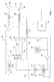
- a vehicle heating/cooling system 100 which comprises an internal combustion engine 102, a consolidated heating/cooling core 104, a refrigerant compressor 106, a refrigerant condenser 108, an inverter 110, a battery 112, a surge tank 114, a pump 116, an electronic control unit (ECU) 118, a first temperature sensor 120, a second temperature sensor 122, and a solenoid valve 124.
- ECU electronice control unit
- Engine 102 is an internal combustion engine. It may be diesel or gasoline. Engine 102 is coupled to and drives a refrigerant compressor 106. Refrigerant compressor 106 is a refrigeration compressor. Engine 102 drives compressor 106 via a belt and pulley arrangement 126 that couples the two together. A pulley 128 on the engine is coupled to a pulley 130 that is drivingly engaged to the refrigerant compressor 106. The two are joined together by a belt 132. An electrically actuated clutch 134 is coupled to and between the refrigerant compressor 106 and the pulley 130. Whenever the electrically actuated clutch 134 is engaged, the pulley 130 drives the refrigerant compressor 106. When the electrically actuated clutch 134 is disengaged, the refrigerant compressor 106 idols and is not driven and the pulley 130 turns freely.
- Engine coolant is transmitted through a closed engine coolant circuit 136 by a pump internal to the engine 102 to conduct hot engine coolant through the closed engine coolant circuit 136.
- the solenoid valve 124 is disposed in the closed engine coolant circuit 136 to regulate the flow of engine coolant through the closed engine coolant circuit 136. When the solenoid valve 124 is closed, the hot engine coolant is not conducted through the closed engine coolant circuit 136. When the solenoid valve 124 is open, hot engine coolant is conducted through the closed engine coolant circuit 136.
- the consolidated heating/cooling core 104 is disposed in the closed engine coolant circuit 136 as well to conduct heat energy from the hot engine coolant to one of the other liquid media passing through the consolidated heating/cooling core 104.
- the consolidated heating/cooling core 104 is a rigid unitary body as best shown in Figure 2 and Figure 4 .
- the consolidated heating/cooling core 104 conducts the hot engine coolant through a first closed path 138.
- the first closed path 138 is considered closed because it prevents the hot engine coolant from being mixed with the other fluid media passing through the consolidated heating/cooling core 104, while permitting heat energy contained in the hot engine coolant to be communicated to a thermally regulated fluid passing through the consolidated heating/cooling core 104.
- the now-cooler engine coolant is then conducted through the remainder of the closed engine coolant circuit 136 and back to the engine 102, thus completing the closed engine coolant circuit 136.
- Refrigerant is compressed by refrigerant compressor 106 and is transmitted through a closed refrigerant circuit 140.
- the closed refrigerant circuit 140 conducts the now-compressed refrigerant into the refrigerant condenser 108, in which the thermal energy contained in the refrigerant is removed and the refrigerant is condensed into a liquid.
- the now-condensed liquid refrigerant is then conducted further through the closed refrigerant circuit 140 and into the consolidated heating/cooling core 104.
- the liquid refrigerant vaporizes in the consolidated heating/cooling core 104 absorbing heat from the thermally regulated fluid passing through the consolidated heating/cooling core 104.
- the refrigerant Once the refrigerant has absorbed sufficient heat and has been vaporized, it is conducted further through the closed refrigerant circuit 140 back to the inlet of the refrigerant compressor 106, thus completing the closed refrigerant circuit 140.
- the consolidated heating/cooling core 104 conducts the liquid refrigerant through a second closed path 142.
- the second closed path 142 is closed because it prevents the liquid refrigerant from being mixed with the other fluid media passing through the consolidated heating/cooling core 104, while permitting heat energy contained in the thermally regulated fluid passing through the consolidated heating/cooling core 104 to be communicated to the liquid refrigerant, thereby vaporizing it.
- the consolidated heating/cooling core 104 comprises a third closed path 144 through which the thermally regulated fluid passes.
- the third closed path 144 prevents the thermally regulated fluid from being mixed with the other fluid media passing through the consolidated heating/cooling core 104, permitting heat energy contained in the thermally regulated fluid to be conveyed to the liquid refrigerant, and permitting heat energy contained in the engine coolant to be conveyed to the thermally regulated fluid over the length of the third closed path 144.
- the third closed path 144 is a part of a closed thermally regulated fluid circuit 146.
- the closed thermally regulated fluid circuit 146 includes the pump 116, which is coupled to the consolidated heating/cooling core 104 to receive the thermally regulated fluid therefrom, and to convey the thermally regulated fluid to a thermally regulated load 148.
- the thermally regulated load 148 comprises the battery 112 and the inverter 110.
- the battery 112 and the inverter 110 include internal heat exchangers to permit heat energy generated in the battery 112 and the inverter 110 to be transmitted from the thermally regulated fluid as necessary to maintain the battery 112 and the inverter 110 at a regulated temperature.
- the internal heat exchangers also permits heat energy in the thermally regulated fluid to be transmitted to the battery 112 and the inverter 110 as necessary to maintain the battery 112 and the inverter 110 at a regulated temperature.
- the surge tank 114 is coupled to the closed thermally regulated fluid circuit 146 to accommodate sudden fluctuations in the fluid flow and fluid pressure of the thermally regulated fluid within the closed thermally regulated fluid circuit 146.
- the temperature in the battery 112 and the inverter 110 are higher than the temperature of the thermally regulated fluid, then heat energy will be conducted into the thermally regulated fluid from the battery 112 and the inverter 110 and the temperature of the battery 112 and the inverter 110 will be correspondingly reduced.
- the temperatures of the battery 112 and the inverter 110 are lower than the temperature of the thermally regulated fluid, then heat energy will be conducted out of the thermally regulated fluid and into the battery 112 and the inverter 110 and the temperature of the battery 112 and the inverter 110 will be correspondingly increased.
- the temperature of the thermally regulated load 148 can be regulated by changing the temperature of the thermally regulated fluid.
- the ECU 118 is configured to monitor and control the temperature of the thermally regulated load 148 in order to maintain the temperature of the thermally regulated load 148 within a predetermined temperature range.
- the ECU 118 is a microprocessor-based electronic control unit of conventional arrangement that includes a digital microprocessor, a non-volatile memory (e.g. ROM) for storing digital instructions that control the operation of the ECU 118 according to a predetermined program, a volatile memory (e.g. RAM) that provides temporary storage of working variables used by the microprocessor in executing its digital instructions, a driver circuit for generating a signal with sufficient power to engage and disengage the electrically actuated clutch 134, and a signal conditioning circuit coupled to the first temperature sensor 120, and the second temperature sensor 122 to receive and condition signals indicative of the temperature of the inverter 110, and the battery 112, temperature sensor 120 respectively.
- a digital microprocessor e.g. ROM
- RAM volatile memory
- driver circuit for generating a signal with sufficient power to engage and disengage the electrically actuated clutch 134
- a signal conditioning circuit coupled to the first temperature sensor 120, and the second temperature sensor 122 to receive and condition signals indicative of the temperature of the in
- the temperature sensor 120 is thermally coupled to the inverter 110 to generate an electrical signal indicative of a temperature of the inverter 110.
- the temperature sensor 122 is thermally coupled to the battery 112 to generate an electrical signal indicative of a temperature of the battery 112.
- the temperature sensor 120 and the temperature sensor 122 are electrically coupled to the signal conditioning circuit of the ECU 118 thereby permitting the ECU 118 to receive signals indicative of the temperature of the inverter 110 and temperature of the battery 112.
- the electrically actuated clutch 134 is coupled to the driver circuit of the ECU 118 to permit the driver circuit to selectively engage and disengage the electrically actuated clutch 134 under the command of the ECU 118.
- the solenoid valve 124 is similarly coupled to the driver circuit of the ECU 118 to be opened and closed thereby under the command of the ECU 118.
- ECU 118 is programmed by the digital instructions to regularly and periodically monitor the signals generated by the temperature sensor 120 and temperature sensor 122.
- the ECU 118 is configured by the digital instructions to compare the temperatures indicated by these signals with a first predetermined threshold temperature and a second predetermined threshold temperature higher than the first predetermined threshold temperature.
- the ECU 118 is programmed by the digital instructions to open the solenoid valve 124, thus permitting the internal combustion engine 102 (by its internal coolant pump) to conduct hot engine coolant through the closed engine coolant circuit 136.
- the closed engine coolant circuit 136 includes the first closed path 138. Hot engine coolant passing through the first closed path 138 transfers heat energy to the thermally regulated fluid passing through the third closed path 144 which is directly thermally coupled to the first closed path 138. This heat transfer heats the thermally regulated fluid.
- the now-heated thermally regulated fluid is then conveyed through the closed thermally regulated fluid circuit 146 through the pump 116 and into the battery 112 and the inverter 110.
- This causes the battery 112 and the inverter 110 to receive thermal energy from the thermally regulated fluid and thereby raises the temperature of the battery 112 and the inverter 110.
- the increased temperature of the battery 112 and the inverter 110 is communicated to the temperature sensor 122 in the temperature sensor 120, respectively.
- the temperature sensor 122 and the temperature sensor 120 communicate this elevated temperature to the ECU 118.
- the ECU 118 senses that the temperature of the battery 112 and the inverter 110 are above the first predetermined threshold temperature, and the ECU 118 is programmed responsively to close the solenoid valve 124.
- the ECU 118 determines that the temperature from either the temperature sensor 120 or the temperature sensor 122 is above the second predetermined threshold temperature, the ECU 118 is programmed by its digital instructions to engage the electrically actuated clutch 134, thus compressing the gaseous refrigerant and conducting it into the refrigerant condenser 108, where its heat energy is removed and the refrigerant is condensed to a liquid refrigerant.
- the liquid refrigerant is then conveyed into the second closed path 142 where heat energy from the thermally regulated fluid passing through the third closed path 144 is conducted into the liquid refrigerant causing it to absorb the heat energy and vaporize. This, in turn, cools the thermally regulated fluid passing through the third closed path 144.
- the pump 116 circulates this now-cool thermally regulated fluid further through the closed thermally regulated fluid circuit 146 and through the battery 112 and the inverter 110 thereby cooling the battery 112 and the inverter 110.
- the now-cooler battery 112 and the inverter 110 communicate this reduced temperature to the temperature sensor 122 and the temperature sensor 120, respectively.
- the temperature sensor 122 and the temperature sensor 120 communicate this reduced temperature to the ECU 118.
- the ECU 118 senses that the temperature of the battery 112 and the inverter 110 are below the second predetermined threshold temperature, and the ECU 118 is programmed by its digital instructions to responsively disengage the electrically actuated clutch 134.
- the vehicle heating/cooling system 100 is thereby configured to regulate the temperature of the thermally regulated load 148 (i.e. the temperatures of the battery 112 and the inverter 110) using the consolidated heating/cooling core 104 to regulate the temperature of the thermally regulated fluid.
- Figure 2 is a schematic diagram of a first embodiment of the consolidated heating/cooling core 104.
- the first closed path 138, the second closed path 142 and the third closed path 144 conduct each of their respective fluids in parallel through the consolidated heating/cooling core 104.
- the first closed path 138, the second closed path 142, and the third closed path 144 are defined by the nested cylinders.
- a first cylinder 200 of the consolidated heating/cooling core 104 defines the first closed path 138, and has a fluid flow inlet 202 and a fluid flow outlet 204.
- the first cylinder 200 is nested inside and surrounded by a second cylinder 206 of the consolidated heating/cooling core 104.
- the space between the second cylinder 206 and a third cylinder 212 defines the third closed path 144 and has a fluid flow inlet 208 and a fluid flow outlet 210.
- the second cylinder 206 is nested inside and surrounded by the third cylinder 212 of the consolidated heating/cooling core 104.
- the space between the second cylinder 206 and the third cylinder 212 defines the second closed path 142 and has a fluid flow inlet 214 and a fluid flow outlet 216.
- heat energy is conducted through the wall of the second cylinder 206 from the thermally regulated fluid passing through the second cylinder 206 to the refrigerant passing through the third cylinder 212.
- the first cylinder 200, the second cylinder 206, and the third cylinder 212 extend longitudinally, generally parallel to a longitudinal axis 218 of the consolidated heating/cooling core 104. If all of the first cylinder 200, the second cylinder 206, and the third cylinder 212 are right circular cylinders (as shown in Figure 3 ), the preferred arrangement is that the first cylinder 200, the second cylinder 206, and the third cylinder 212 be arranged concentric about the longitudinal axis 218.
- first closed path 138 and the second closed path 142 are isolated from each other, such that no (or only a limited amount of) heat transfer can occur directly from liquid traveling through the first closed path 138 and liquid traveling through the second closed path 142.
- Figure 4 is a schematic diagram of a second embodiment of the consolidated heating/cooling core 104.
- first closed path 138, and the third closed path 144 conduct each of their respective fluids in parallel through a first section 400 of the consolidated heating/cooling core 104.
- the second closed path 142 and the third closed path 144 conduct each of their respective fluids in parallel through a second section 402 of the consolidated heating/cooling core 104.
- the first section 400 and the second section 402 are disposed in sequential longitudinal portions of
- the second closed path 142 and the third closed path 144 conduct each of their respective fluids in parallel through a second section 402 of the consolidated heating/cooling core 104.
- the second closed path 142 and the third closed path 144 are arranged as nested cylinders.
- a first cylinder 404 of the consolidated heating/cooling core 104 defines the first closed path 138 and has a fluid flow inlet 406 (202 in Figure 1 ), and a fluid flow outlet 408 (204 in Figure 1 ).
- the first cylinder 404 is nested inside and surrounded by a second cylinder 410 of the consolidated heating/cooling core 104.
- the space between the second cylinder 410 and the first cylinder 404 defines the third closed path 144 and has a fluid flow inlet 412 (208 in Figure 1 ) and a fluid flow outlet 414 (210 in Figure 1 ).
- heat energy is conducted through the wall of the first cylinder 404 from the engine coolant in the closed engine coolant circuit 136 to the thermally regulated fluid passing through the second cylinder 410.
- a third cylinder 416 of the consolidated heating/cooling core 104 defines the second closed path 142 and has a fluid flow inlet 418 (214 in Figure 1 ) and a fluid flow outlet 420 (216 in Figure 1 ).
- the first cylinder 404, the second cylinder 410 and the third cylinder 416 extend longitudinally, generally parallel to a longitudinal axis 422 of the consolidated heating/cooling core 104. If all of the first cylinder 200, the second cylinder 206, and the third cylinder 212 are right circular cylinders (as shown in Figure 5 ), the preferred arrangement is that the first cylinder 404, the second cylinder 410, and the third cylinder 416 be arranged concentric about the longitudinal axis 422.
- first closed path 138 and the second closed path 142 are isolated from each other, such that no (or only a limited amount of) heat transfer can occur directly from liquid traveling through the first closed path 138 and liquid traveling through the second the second closed path 142.
- one or more of the fluid flow inlet 406, the fluid flow inlet 412 and the fluid flow inlet 418 would become fluid flow outlets, and one or more of the fluid flow outlet 408, the fluid flow outlet 414, and the fluid flow outlet 420 would become fluid flow inlets.
- the conduit connected to its corresponding inlet (as shown in Figure 2 ) would be moved to its corresponding outlet (as shown in Figure 2 ), and the conduit that was connected to its corresponding outlet would be moved to its corresponding inlet.
- a belt and pulley drive arrangement is shown as well as an electrically actuated clutch.
- Other arrangements may comprise gears, pulleys, shafts, belts, mechanical clutches, hydraulic clutches, hydraulic motors, and hydraulic clutches.
- the thermally regulated load 148 may comprise a radiator disposed to cool and heat ambient air in an operator compartment of the vehicle.
- a tube and shell heat exchanger arrangement may be employed in which a first plurality of cylinders extending in parallel define the first closed path 138 and a second plurality of cylinders extending in parallel define the second closed path 142, and a common space inside the shell and surrounding the first plurality of cylinders and the second plurality of cylinders define the third closed path 144.
- This arrangement has the additional advantage of providing greater tubular surface area for heat transfer than would be provided with the three-cylinder embodiments illustrated in Figure 2 and Figure 4 .
Landscapes
- Engineering & Computer Science (AREA)
- Mechanical Engineering (AREA)
- Physics & Mathematics (AREA)
- Thermal Sciences (AREA)
- General Engineering & Computer Science (AREA)
- Chemical & Material Sciences (AREA)
- Sustainable Development (AREA)
- Sustainable Energy (AREA)
- Life Sciences & Earth Sciences (AREA)
- Combustion & Propulsion (AREA)
- Manufacturing & Machinery (AREA)
- Chemical Kinetics & Catalysis (AREA)
- Electrochemistry (AREA)
- General Chemical & Material Sciences (AREA)
- Cooling, Air Intake And Gas Exhaust, And Fuel Tank Arrangements In Propulsion Units (AREA)
- Air-Conditioning For Vehicles (AREA)
- Hybrid Electric Vehicles (AREA)
Abstract
Description
- This invention relates to vehicle heating/cooling systems. More particularly, it relates to heat exchangers for vehicle heating/cooling systems. Even more particularly, it relates to consolidated heating/cooling cores for such heat exchangers.
- Vehicle heating/cooling systems typically employed separate heat exchangers for heating circuits and for cooling circuits. Providing the separate heat exchangers requires additional space and plumbing, including additional valves and conduits to direct the flow to the separate heat exchangers in the system.
- This is a particular problem for vehicles such as hybrid vehicles that employ electric batteries to drive the vehicle. These electric batteries must be maintained within a narrow range of temperatures in order to keep them operating at peak efficiency and without damage.
- It is an object of this invention to provide an improved vehicle heating/cooling system in which a heat exchanger with a consolidated heating/cooling core is employed to reduce space and maintain temperatures at appropriate levels.
- It is also an object of this invention to provide a consolidated heating/cooling core for the vehicle heating/cooling system.
- A vehicle heating/cooling system for a vehicle is provided comprising an internal combustion engine coupled to a closed engine coolant circuit to recirculate engine coolant therethrough; a refrigerant compressor coupled to a closed refrigerant circuit to recirculate refrigerant therethrough, wherein the refrigerant compressor is coupled to the internal combustion engine to be driven thereby; a closed thermally regulated fluid circuit to recirculate thermally regulated fluid therethrough; and a consolidated heating/cooling core coupled to the closed engine coolant circuit, to the closed refrigerant circuit and to the closed thermally regulated fluid circuit.
- The consolidated heating/cooling core may define a first closed path for conducting the engine coolant therethrough, and the consolidated heating/cooling core may define a second closed path for conducting the refrigerant therethrough, and the consolidated heating/cooling core may define a third closed path for conducting the thermally regulated fluid therethrough.
- The first closed path, the second closed path and the third closed path may be defined by a plurality of cylinders.
- The plurality of cylinders may comprise a first cylinder, a second cylinder, and a third cylinder, and each cylinder of the plurality of cylinders may have an inner surface and an outer surface, and the first cylinder may be surrounded by the second cylinder which may be surrounded by the third cylinder.
- At least one of the first closed path and the second closed path may be defined by an inner surface of the first cylinder, and at least another of the first closed path and the second closed path may be defined by a space between the outer surface of the second cylinder and the inner surface of the third cylinder, and the third closed path may be defined by the space between the outer surface of the first cylinder and the inner surface of the second cylinder.
- The plurality of cylinders may comprise a first cylinder, a second cylinder, and a third cylinder and each cylinder of the plurality of cylinders may have an inner surface and an outer surface, and the first cylinder may be surrounded by the second cylinder and the third cylinder may be surrounded by the second cylinder.
- The first closed path may be defined by an inner surface of the first cylinder, and the second closed path may be defined by an inner surface of the third cylinder, and the third closed path may be defined by a space between the outer surface of the first cylinder and the inner surface of the second cylinder, and the third closed path may be defined by the space between the outer surface of the third cylinder and the inner surface of the second cylinder.
- The plurality of cylinders may be concentric.
- Each cylinder of the plurality of cylinders may be nested within at least another cylinder of the plurality of cylinders.
- The closed thermally regulated fluid circuit may pass through a thermally regulated load, and the thermally regulated load may comprise a battery.
- The closed thermally regulated fluid circuit may pass through a thermally regulated load, and further wherein the thermally regulated load comprises an inverter.
- The consolidated heating/cooling core may be a rigid, unitary body.
- A fluid flow direction through one of the first closed path, the second closed path and the third closed path may be opposite to a fluid flow direction through the other two of the first closed path, the second closed path and the third closed path.
- In accordance with another aspect of the invention, a consolidated heating/cooling core is provided for a vehicle heating/cooling system comprising a closed engine coolant circuit for conducting engine coolant therethrough, a closed refrigerant circuit for conducting refrigerant therethrough, and a closed thermally regulated fluid circuit for conducting thermally regulated fluid therethrough, the consolidated heating/cooling core comprising: a first closed path for conducting the engine coolant therethrough; a second closed path for conducting the refrigerant therethrough; and a third closed path for conducting the thermally regulated fluid therethrough.
- The first closed path, the second closed path and the third closed path may be defined by a plurality of cylinders.
- The plurality of cylinders may comprise a first cylinder, a second cylinder, and a third cylinder, and each cylinder of the plurality of cylinders may have an inner surface and an outer surface, and the first cylinder may be surrounded by the second cylinder which may be surrounded by the third cylinder.
- At least one of the first closed path and the second closed path may be defined by an inner surface of the first cylinder, and at least another of the first closed path and the second closed path may be defined by a space between the outer surface of the second cylinder and the inner surface of the third cylinder, and the third closed path may be defined by the space between the outer surface of the first cylinder and the inner surface of the second cylinder.
- The plurality of cylinders may comprise a first cylinder, a second cylinder, and a third cylinder and each cylinder of the plurality of cylinders may have an inner surface and an outer surface, and the first cylinder may be surrounded by the second cylinder and the third cylinder may be surrounded by the second cylinder.
- The first closed path may be defined by an inner surface of the first cylinder, and the second closed path may be defined by an inner surface of the third cylinder, and the third closed path may be defined by a space between the outer surface of the first cylinder and the inner surface of the second cylinder, and the third closed path may be defined by the space between the outer surface of the third cylinder and the inner surface of the second cylinder.
- Each cylinder of the plurality of cylinders may be concentric with another cylinder of the plurality of cylinders.
-
-
Figure 1 is a schematic diagram of a vehicle heating/cooling system employing a consolidated heating/cooling core in accordance with the present invention. -
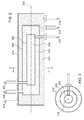
Figure 2 is a cross-sectional view of a first embodiment of the consolidated heating/cooling core for the vehicle heating/cooling system ofFigure 1 taken along its longitudinal centerline. -
Figure 3 is a cross-sectional view of the embodiment ofFigure 2 taken at section line 3-3 inFigure 2 . -
Figure 4 is a cross-sectional view of a second embodiment of the consolidated heating/cooling core for the vehicle heating/cooling system ofFigure 1 taken along its longitudinal centerline. -
Figure 5 is a cross-sectional view of the embodiment ofFigure 4 taken at section line 5-5 inFigure 4 . - In
Figure 1 , a vehicle heating/cooling system 100 is shown which comprises aninternal combustion engine 102, a consolidated heating/cooling core 104, arefrigerant compressor 106, arefrigerant condenser 108, aninverter 110, abattery 112, asurge tank 114, apump 116, an electronic control unit (ECU) 118, afirst temperature sensor 120, asecond temperature sensor 122, and asolenoid valve 124. -
Engine 102 is an internal combustion engine. It may be diesel or gasoline.Engine 102 is coupled to and drives arefrigerant compressor 106.Refrigerant compressor 106 is a refrigeration compressor.Engine 102 drivescompressor 106 via a belt andpulley arrangement 126 that couples the two together. Apulley 128 on the engine is coupled to apulley 130 that is drivingly engaged to therefrigerant compressor 106. The two are joined together by abelt 132. An electrically actuatedclutch 134 is coupled to and between therefrigerant compressor 106 and thepulley 130. Whenever the electrically actuatedclutch 134 is engaged, thepulley 130 drives therefrigerant compressor 106. When the electrically actuatedclutch 134 is disengaged, therefrigerant compressor 106 idols and is not driven and thepulley 130 turns freely. - Engine coolant is transmitted through a closed
engine coolant circuit 136 by a pump internal to theengine 102 to conduct hot engine coolant through the closedengine coolant circuit 136. Thesolenoid valve 124 is disposed in the closedengine coolant circuit 136 to regulate the flow of engine coolant through the closedengine coolant circuit 136. When thesolenoid valve 124 is closed, the hot engine coolant is not conducted through the closedengine coolant circuit 136. When thesolenoid valve 124 is open, hot engine coolant is conducted through the closedengine coolant circuit 136. - The consolidated heating/
cooling core 104 is disposed in the closedengine coolant circuit 136 as well to conduct heat energy from the hot engine coolant to one of the other liquid media passing through the consolidated heating/cooling core 104. The consolidated heating/cooling core 104 is a rigid unitary body as best shown inFigure 2 andFigure 4 . - The consolidated heating/
cooling core 104 conducts the hot engine coolant through a first closedpath 138. The first closedpath 138 is considered closed because it prevents the hot engine coolant from being mixed with the other fluid media passing through the consolidated heating/cooling core 104, while permitting heat energy contained in the hot engine coolant to be communicated to a thermally regulated fluid passing through the consolidated heating/cooling core 104. Having passed through the consolidated heating/cooling core 104, the now-cooler engine coolant is then conducted through the remainder of the closedengine coolant circuit 136 and back to theengine 102, thus completing the closedengine coolant circuit 136. - Refrigerant is compressed by
refrigerant compressor 106 and is transmitted through a closedrefrigerant circuit 140. The closedrefrigerant circuit 140 conducts the now-compressed refrigerant into therefrigerant condenser 108, in which the thermal energy contained in the refrigerant is removed and the refrigerant is condensed into a liquid. - The now-condensed liquid refrigerant is then conducted further through the closed
refrigerant circuit 140 and into the consolidated heating/cooling core 104. The liquid refrigerant vaporizes in the consolidated heating/cooling core 104 absorbing heat from the thermally regulated fluid passing through the consolidated heating/cooling core 104. Once the refrigerant has absorbed sufficient heat and has been vaporized, it is conducted further through the closedrefrigerant circuit 140 back to the inlet of therefrigerant compressor 106, thus completing the closedrefrigerant circuit 140. - The consolidated heating/
cooling core 104 conducts the liquid refrigerant through a second closedpath 142. The second closedpath 142 is closed because it prevents the liquid refrigerant from being mixed with the other fluid media passing through the consolidated heating/cooling core 104, while permitting heat energy contained in the thermally regulated fluid passing through the consolidated heating/cooling core 104 to be communicated to the liquid refrigerant, thereby vaporizing it. - The consolidated heating/
cooling core 104 comprises a thirdclosed path 144 through which the thermally regulated fluid passes. The thirdclosed path 144 prevents the thermally regulated fluid from being mixed with the other fluid media passing through the consolidated heating/cooling core 104, permitting heat energy contained in the thermally regulated fluid to be conveyed to the liquid refrigerant, and permitting heat energy contained in the engine coolant to be conveyed to the thermally regulated fluid over the length of the thirdclosed path 144. - The third
closed path 144 is a part of a closed thermally regulatedfluid circuit 146. The closed thermally regulatedfluid circuit 146 includes thepump 116, which is coupled to the consolidated heating/cooling core 104 to receive the thermally regulated fluid therefrom, and to convey the thermally regulated fluid to a thermally regulatedload 148. In this case, the thermally regulatedload 148 comprises thebattery 112 and theinverter 110. Thebattery 112 and theinverter 110 include internal heat exchangers to permit heat energy generated in thebattery 112 and theinverter 110 to be transmitted from the thermally regulated fluid as necessary to maintain thebattery 112 and theinverter 110 at a regulated temperature. The internal heat exchangers also permits heat energy in the thermally regulated fluid to be transmitted to thebattery 112 and theinverter 110 as necessary to maintain thebattery 112 and theinverter 110 at a regulated temperature. - The
surge tank 114 is coupled to the closed thermally regulatedfluid circuit 146 to accommodate sudden fluctuations in the fluid flow and fluid pressure of the thermally regulated fluid within the closed thermally regulatedfluid circuit 146. - If the temperature in the
battery 112 and theinverter 110 are higher than the temperature of the thermally regulated fluid, then heat energy will be conducted into the thermally regulated fluid from thebattery 112 and theinverter 110 and the temperature of thebattery 112 and theinverter 110 will be correspondingly reduced. - If the temperatures of the
battery 112 and theinverter 110 are lower than the temperature of the thermally regulated fluid, then heat energy will be conducted out of the thermally regulated fluid and into thebattery 112 and theinverter 110 and the temperature of thebattery 112 and theinverter 110 will be correspondingly increased. - Thus the temperature of the thermally regulated
load 148 can be regulated by changing the temperature of the thermally regulated fluid. - The
ECU 118 is configured to monitor and control the temperature of the thermally regulatedload 148 in order to maintain the temperature of the thermally regulatedload 148 within a predetermined temperature range. - The
ECU 118 is a microprocessor-based electronic control unit of conventional arrangement that includes a digital microprocessor, a non-volatile memory (e.g. ROM) for storing digital instructions that control the operation of theECU 118 according to a predetermined program, a volatile memory (e.g. RAM) that provides temporary storage of working variables used by the microprocessor in executing its digital instructions, a driver circuit for generating a signal with sufficient power to engage and disengage the electrically actuated clutch 134, and a signal conditioning circuit coupled to thefirst temperature sensor 120, and thesecond temperature sensor 122 to receive and condition signals indicative of the temperature of theinverter 110, and thebattery 112,temperature sensor 120 respectively. - The
temperature sensor 120 is thermally coupled to theinverter 110 to generate an electrical signal indicative of a temperature of theinverter 110. - The
temperature sensor 122 is thermally coupled to thebattery 112 to generate an electrical signal indicative of a temperature of thebattery 112. - The
temperature sensor 120 and thetemperature sensor 122 are electrically coupled to the signal conditioning circuit of theECU 118 thereby permitting theECU 118 to receive signals indicative of the temperature of theinverter 110 and temperature of thebattery 112. - The electrically actuated clutch 134 is coupled to the driver circuit of the
ECU 118 to permit the driver circuit to selectively engage and disengage the electrically actuated clutch 134 under the command of theECU 118. - The
solenoid valve 124 is similarly coupled to the driver circuit of theECU 118 to be opened and closed thereby under the command of theECU 118. -
ECU 118 is programmed by the digital instructions to regularly and periodically monitor the signals generated by thetemperature sensor 120 andtemperature sensor 122. TheECU 118 is configured by the digital instructions to compare the temperatures indicated by these signals with a first predetermined threshold temperature and a second predetermined threshold temperature higher than the first predetermined threshold temperature. - If either of the temperatures indicated by the
temperature sensor 120 or thetemperature sensor 122 is below the first predetermined threshold temperature, theECU 118 is programmed by the digital instructions to open thesolenoid valve 124, thus permitting the internal combustion engine 102 (by its internal coolant pump) to conduct hot engine coolant through the closedengine coolant circuit 136. The closedengine coolant circuit 136 includes the firstclosed path 138. Hot engine coolant passing through the firstclosed path 138 transfers heat energy to the thermally regulated fluid passing through the thirdclosed path 144 which is directly thermally coupled to the firstclosed path 138. This heat transfer heats the thermally regulated fluid. The now-heated thermally regulated fluid is then conveyed through the closed thermally regulatedfluid circuit 146 through thepump 116 and into thebattery 112 and theinverter 110. This causes thebattery 112 and theinverter 110 to receive thermal energy from the thermally regulated fluid and thereby raises the temperature of thebattery 112 and theinverter 110. The increased temperature of thebattery 112 and theinverter 110 is communicated to thetemperature sensor 122 in thetemperature sensor 120, respectively. Thetemperature sensor 122 and thetemperature sensor 120 communicate this elevated temperature to theECU 118. Eventually, theECU 118 senses that the temperature of thebattery 112 and theinverter 110 are above the first predetermined threshold temperature, and theECU 118 is programmed responsively to close thesolenoid valve 124. - If the
ECU 118 determines that the temperature from either thetemperature sensor 120 or thetemperature sensor 122 is above the second predetermined threshold temperature, theECU 118 is programmed by its digital instructions to engage the electrically actuated clutch 134, thus compressing the gaseous refrigerant and conducting it into therefrigerant condenser 108, where its heat energy is removed and the refrigerant is condensed to a liquid refrigerant. The liquid refrigerant is then conveyed into the secondclosed path 142 where heat energy from the thermally regulated fluid passing through the thirdclosed path 144 is conducted into the liquid refrigerant causing it to absorb the heat energy and vaporize. This, in turn, cools the thermally regulated fluid passing through the thirdclosed path 144. Thepump 116 circulates this now-cool thermally regulated fluid further through the closed thermally regulatedfluid circuit 146 and through thebattery 112 and theinverter 110 thereby cooling thebattery 112 and theinverter 110. The now-cooler battery 112 and theinverter 110 communicate this reduced temperature to thetemperature sensor 122 and thetemperature sensor 120, respectively. Thetemperature sensor 122 and thetemperature sensor 120 communicate this reduced temperature to theECU 118. Eventually, theECU 118 senses that the temperature of thebattery 112 and theinverter 110 are below the second predetermined threshold temperature, and theECU 118 is programmed by its digital instructions to responsively disengage the electrically actuatedclutch 134. - The vehicle heating/
cooling system 100 is thereby configured to regulate the temperature of the thermally regulated load 148 (i.e. the temperatures of thebattery 112 and the inverter 110) using the consolidated heating/cooling core 104 to regulate the temperature of the thermally regulated fluid. -
Figure 2 is a schematic diagram of a first embodiment of the consolidated heating/cooling core 104. In this embodiment, the firstclosed path 138, the secondclosed path 142 and the thirdclosed path 144 conduct each of their respective fluids in parallel through the consolidated heating/cooling core 104. In this arrangement, the firstclosed path 138, the secondclosed path 142, and the thirdclosed path 144 are defined by the nested cylinders. - A
first cylinder 200 of the consolidated heating/cooling core 104 defines the firstclosed path 138, and has afluid flow inlet 202 and afluid flow outlet 204. - The
first cylinder 200 is nested inside and surrounded by asecond cylinder 206 of the consolidated heating/cooling core 104. The space between thesecond cylinder 206 and athird cylinder 212 defines the thirdclosed path 144 and has afluid flow inlet 208 and afluid flow outlet 210. - By this arrangement, heat energy is conducted through the wall of the
first cylinder 200 from the engine coolant to the thermally regulated fluid passing through thesecond cylinder 206. - The
second cylinder 206 is nested inside and surrounded by thethird cylinder 212 of the consolidated heating/cooling core 104. The space between thesecond cylinder 206 and thethird cylinder 212 defines the secondclosed path 142 and has afluid flow inlet 214 and afluid flow outlet 216. - By this arrangement, heat energy is conducted through the wall of the
second cylinder 206 from the thermally regulated fluid passing through thesecond cylinder 206 to the refrigerant passing through thethird cylinder 212. - The
first cylinder 200, thesecond cylinder 206, and thethird cylinder 212 extend longitudinally, generally parallel to alongitudinal axis 218 of the consolidated heating/cooling core 104. If all of thefirst cylinder 200, thesecond cylinder 206, and thethird cylinder 212 are right circular cylinders (as shown inFigure 3 ), the preferred arrangement is that thefirst cylinder 200, thesecond cylinder 206, and thethird cylinder 212 be arranged concentric about thelongitudinal axis 218. - In the arrangement of
Figure 2 , the firstclosed path 138 and the secondclosed path 142 are isolated from each other, such that no (or only a limited amount of) heat transfer can occur directly from liquid traveling through the firstclosed path 138 and liquid traveling through the secondclosed path 142. - In the arrangement of
Figure 2 , all flow through the cylinders is in the same direction. Depending upon the size and spacing of the cylinders and the cooling and heating requirements of the thermally regulatedload 148, one, two, or all of the flows can be reversed in flow direction to provide a counter flow regime for improved heat transfer. In such an arrangement, one or more of thefluid flow inlet 202, thefluid flow inlet 208, and thefluid flow inlet 214 would become fluid flow outlets, and one or more of thefluid flow outlet 204, thefluid flow outlet 210, and thefluid flow outlet 216 would become fluid flow inlets. -
Figure 4 is a schematic diagram of a second embodiment of the consolidated heating/cooling core 104. - In this embodiment, the first
closed path 138, and the thirdclosed path 144 conduct each of their respective fluids in parallel through afirst section 400 of the consolidated heating/cooling core 104. The secondclosed path 142 and the thirdclosed path 144 conduct each of their respective fluids in parallel through asecond section 402 of the consolidated heating/cooling core 104. Thefirst section 400 and thesecond section 402 are disposed in sequential longitudinal portions of - In this embodiment also, the second
closed path 142 and the thirdclosed path 144 conduct each of their respective fluids in parallel through asecond section 402 of the consolidated heating/cooling core 104. In thesecond section 402, the secondclosed path 142 and the thirdclosed path 144 are arranged as nested cylinders. - In the
first section 400, afirst cylinder 404 of the consolidated heating/cooling core 104 defines the firstclosed path 138 and has a fluid flow inlet 406 (202 inFigure 1 ), and a fluid flow outlet 408 (204 inFigure 1 ). - The
first cylinder 404 is nested inside and surrounded by asecond cylinder 410 of the consolidated heating/cooling core 104. The space between thesecond cylinder 410 and thefirst cylinder 404 defines the thirdclosed path 144 and has a fluid flow inlet 412 (208 inFigure 1 ) and a fluid flow outlet 414 (210 inFigure 1 ). - By this arrangement, heat energy is conducted through the wall of the
first cylinder 404 from the engine coolant in the closedengine coolant circuit 136 to the thermally regulated fluid passing through thesecond cylinder 410. - In the
second section 402, athird cylinder 416 of the consolidated heating/cooling core 104 defines the secondclosed path 142 and has a fluid flow inlet 418 (214 inFigure 1 ) and a fluid flow outlet 420 (216 inFigure 1 ). - The
first cylinder 404, thesecond cylinder 410 and thethird cylinder 416 extend longitudinally, generally parallel to alongitudinal axis 422 of the consolidated heating/cooling core 104. If all of thefirst cylinder 200, thesecond cylinder 206, and thethird cylinder 212 are right circular cylinders (as shown inFigure 5 ), the preferred arrangement is that thefirst cylinder 404, thesecond cylinder 410, and thethird cylinder 416 be arranged concentric about thelongitudinal axis 422. - In the arrangement of
Figure 4 , the firstclosed path 138 and the secondclosed path 142 are isolated from each other, such that no (or only a limited amount of) heat transfer can occur directly from liquid traveling through the firstclosed path 138 and liquid traveling through the second the secondclosed path 142. - In the arrangement of
Figure 4 , all fluid flows through the firstclosed path 138, the secondclosed path 142, and the thirdclosed path 144 are in the same flow direction. Depending upon the size and spacing of the cylinders and the cooling and heating requirements of the thermally regulatedload 148, one of the fluid flows can be reversed in flow direction to provide a counter flow regime for improved heat transfer. - In such an arrangement, one or more of the fluid flow inlet 406, the fluid flow inlet 412 and the
fluid flow inlet 418 would become fluid flow outlets, and one or more of thefluid flow outlet 408, thefluid flow outlet 414, and thefluid flow outlet 420 would become fluid flow inlets. To reverse the flow direction for any one of the firstclosed path 138, the secondclosed path 142, and the thirdclosed path 144 as shown inFigure 2 , the conduit connected to its corresponding inlet (as shown inFigure 2 ) would be moved to its corresponding outlet (as shown inFigure 2 ), and the conduit that was connected to its corresponding outlet would be moved to its corresponding inlet. - It should be understood that the particular embodiments shown and discussed herein are not the only ways in which the invention can exist. They are merely current preferred embodiments of the invention. One skilled in the art of vehicle heating/cooling system design and manufacture can readily see other variations that would also fall within the scope of the appended claims.
- For example, a belt and pulley drive arrangement is shown as well as an electrically actuated clutch. Other arrangements may comprise gears, pulleys, shafts, belts, mechanical clutches, hydraulic clutches, hydraulic motors, and hydraulic clutches.
- As another example, the thermally regulated
load 148 may comprise a radiator disposed to cool and heat ambient air in an operator compartment of the vehicle. - As another arrangement, rather than single concentric cylinders defining the first
closed path 138, the secondclosed path 142, and the thirdclosed path 144, a tube and shell heat exchanger arrangement may be employed in which a first plurality of cylinders extending in parallel define the firstclosed path 138 and a second plurality of cylinders extending in parallel define the secondclosed path 142, and a common space inside the shell and surrounding the first plurality of cylinders and the second plurality of cylinders define the thirdclosed path 144. This arrangement has the additional advantage of providing greater tubular surface area for heat transfer than would be provided with the three-cylinder embodiments illustrated inFigure 2 andFigure 4 .
Claims (15)
- A vehicle heating/cooling system (100) for a vehicle comprising:an internal combustion engine (102) coupled to a closed engine coolant circuit (136) to recirculate engine coolant therethrough;a refrigerant compressor (106) coupled to a closed refrigerant circuit (140) to recirculate refrigerant therethrough, wherein the refrigerant compressor is coupled to the internal combustion engine (102) to be driven thereby;a closed thermally regulated fluid circuit (146) to recirculate thermally regulated fluid therethrough; anda consolidated heating/cooling core (104) coupled to the closed engine coolant circuit (136), to the closed refrigerant circuit (140) and to the closed thermally regulated fluid circuit (146).
- The vehicle heating/cooling system (100) of Claim 1, wherein the consolidated heating/cooling core (104) defines a first closed path (138) for conducting the engine coolant therethrough, wherein the consolidated heating/cooling core (104) defines a second closed path (142) for conducting the refrigerant therethrough, and wherein the consolidated heating/cooling core (104) defines a third closed path (144) for conducting the thermally regulated fluid therethrough.
- The vehicle heating/cooling system (100) of Claim 2, wherein the first closed path (138), the second closed path (142) and the third closed path (144) are defined by a plurality of cylinders (200, 206, 212, 404, 410, 416).
- The vehicle heating/cooling system (100) of Claim 3, wherein the plurality of cylinders (200, 206, 212) comprises a first cylinder (200), a second cylinder (206), and a third cylinder (212), and further wherein each cylinder of the plurality of cylinders (200, 206, 212) has an inner surface and an outer surface, and further wherein the first cylinder (200) is surrounded by the second cylinder (206) which is surrounded by the third cylinder (212).
- The vehicle heating/cooling system (100) of Claim 4, wherein at least one of the first closed path (138) and the second closed path (142) is defined by an inner surface of the first cylinder (200), and further wherein at least another of the first closed path (138) and the second closed path (142) is defined by a space between the outer surface of the second cylinder (206) and the inner surface of the third cylinder (212), and further wherein the third closed path (144) is defined by the space between the outer surface of the first cylinder (200) and the inner surface of the second cylinder (206).
- The vehicle heating/cooling system (100) of Claim 3, wherein the plurality of cylinders (404, 416, 410) comprises a first cylinder (404), a second cylinder (410), and a third cylinder (416), and further wherein each cylinder of the plurality of cylinders (404, 416, 410) has an inner surface and an outer surface, and further wherein the first cylinder (404) is surrounded by the second cylinder (410) and the third cylinder (416) is surrounded by the second cylinder (410).
- The vehicle heating/cooling system (100) of Claim 6, wherein the first closed path (138) is defined by an inner surface of the first cylinder (404), and further wherein the second closed path (142) is defined by an inner surface of the third cylinder (416), and further wherein the third closed path (144) is defined by a space between the outer surface of the first cylinder (404) and the inner surface of the second cylinder (410), and further wherein the third closed path (144) is defined by the space between the outer surface of the third cylinder (416) and the inner surface of the second cylinder (410).
- The vehicle heating/cooling system (100) of Claim 3, wherein the plurality of cylinders (200, 206, 212, 404, 410, 416) is concentric.
- The vehicle heating/cooling system (100) of Claim 3, wherein each cylinder of the plurality of cylinders (200, 206, 404, 416) is nested within at least another cylinder of the plurality of cylinders (206, 212, 410).
- The vehicle heating/cooling system (100) of Claim 1, wherein the closed thermally regulated fluid circuit (146) passes through a thermally regulated load (148), and further wherein the thermally regulated load (148) comprises a battery (112).
- The vehicle heating/cooling system (100) of Claim 10, wherein the closed thermally regulated fluid circuit (146) passes through a thermally regulated load (148), and further wherein the thermally regulated load (148) comprises an inverter (110).
- The vehicle heating/cooling system (100) of Claim 1, wherein the consolidated heating/cooling core (104) is a rigid, unitary body.
- The vehicle heating/cooling system (100) of Claim 2, wherein a fluid flow direction through one of the first closed path (138), the second closed path (142) and the third closed path (144) is opposite to a fluid flow direction through the other two of the first closed path (138), the second closed path (142) and the third closed path (144).
- A consolidated heating/cooling core (104) for a vehicle heating/cooling system (100) of a vehicle, the vehicle heating/cooling system (100) comprising a closed engine coolant circuit (136) for conducting engine coolant therethrough, a closed refrigerant circuit (140) for conducting refrigerant therethrough, and a closed thermally regulated fluid circuit (146) for conducting thermally regulated fluid therethrough, the consolidated heating/cooling core (104) comprising:a first closed path (138) for conducting the engine coolant therethrough;a second closed path (142) for conducting the refrigerant therethrough; anda third closed path (144) for conducting the thermally regulated fluid therethrough.
- The consolidated heating/cooling core (104) of Claim 14, wherein the first closed path (138), the second closed path (142) and the third closed path (144) are defined by a plurality of cylinders (200, 206, 212, 404, 410, 416).
Applications Claiming Priority (1)
| Application Number | Priority Date | Filing Date | Title |
|---|---|---|---|
| US13/890,814 US9786963B2 (en) | 2013-05-09 | 2013-05-09 | Vehicle heating/cooling system with consolidated heating/cooling core |
Publications (3)
| Publication Number | Publication Date |
|---|---|
| EP2801492A2 true EP2801492A2 (en) | 2014-11-12 |
| EP2801492A3 EP2801492A3 (en) | 2015-03-04 |
| EP2801492B1 EP2801492B1 (en) | 2020-05-20 |
Family
ID=50513152
Family Applications (1)
| Application Number | Title | Priority Date | Filing Date |
|---|---|---|---|
| EP14165610.8A Active EP2801492B1 (en) | 2013-05-09 | 2014-04-23 | Vehicle heating/cooling system with consolidated heating/cooling core |
Country Status (6)
| Country | Link |
|---|---|
| US (1) | US9786963B2 (en) |
| EP (1) | EP2801492B1 (en) |
| CN (1) | CN104139681B (en) |
| AU (1) | AU2014202381B2 (en) |
| BR (1) | BR102014011121B1 (en) |
| RU (1) | RU2652365C2 (en) |
Cited By (1)
| Publication number | Priority date | Publication date | Assignee | Title |
|---|---|---|---|---|
| EP3689647A4 (en) * | 2017-09-29 | 2021-06-23 | Aiways Automobile (Shanghai) Co., Ltd | Automobile thermal management system, and automobile having same |
Families Citing this family (12)
| Publication number | Priority date | Publication date | Assignee | Title |
|---|---|---|---|---|
| DE102015101186B4 (en) * | 2015-01-28 | 2024-04-18 | Dr. Ing. H.C. F. Porsche Aktiengesellschaft | Air conditioning circuit for an electrically driven motor vehicle, and method for preheating a traction battery of an electrically driven motor vehicle |
| CN110481267B (en) * | 2015-06-17 | 2021-06-18 | 杭州三花研究院有限公司 | Vehicle energy management system and control method thereof |
| JP6607137B2 (en) * | 2016-04-21 | 2019-11-20 | 株式会社デンソー | Power storage device |
| CN106004338B (en) * | 2016-07-27 | 2019-06-25 | 宁波吉利汽车研究开发有限公司 | Automotive thermal tube manages system and automobile |
| KR102399618B1 (en) * | 2017-05-30 | 2022-05-18 | 현대자동차주식회사 | Hvac system of vehicle |
| US10252597B2 (en) * | 2017-08-01 | 2019-04-09 | Gm Global Technology Llc | Joint active thermal management system and control logic for hybrid and electric vehicles |
| JP6952199B2 (en) * | 2018-01-24 | 2021-10-20 | プラナフ ヴィカス(インディア)プライベート リミテッドPranav Vikas (India) Pvt. Ltd. | Electric vehicle heat management system suitable for hot climate areas |
| JP6992668B2 (en) * | 2018-04-25 | 2022-01-13 | トヨタ自動車株式会社 | Vehicle drive system cooling system |
| EP3875263A1 (en) | 2020-03-06 | 2021-09-08 | TI Automotive (Fuldabrück) GmbH | Tube construct |
| JP7327221B2 (en) * | 2020-03-10 | 2023-08-16 | トヨタ自動車株式会社 | In-vehicle temperature control system |
| US11541719B1 (en) | 2021-07-14 | 2023-01-03 | GM Global Technology Operations LLC | Active thermal management systems and control logic for heat exchanger storage of refrigerant |
| DE102022122052A1 (en) | 2022-08-31 | 2024-02-29 | Claas Industrietechnik Gmbh | Agricultural working machine |
Family Cites Families (10)
| Publication number | Priority date | Publication date | Assignee | Title |
|---|---|---|---|---|
| GB692885A (en) | 1949-12-28 | 1953-06-17 | Brown Fintube Co | Improvements in the manufacture of heat exchangers |
| US3700165A (en) * | 1971-01-11 | 1972-10-24 | Gen Motors Corp | Thumbwheel vacuum thermostat |
| DE4235217C2 (en) * | 1992-10-14 | 1994-12-01 | Hagenuk Fahrzeugklima Gmbh | Process for heating or cooling a room |
| DE19860057C5 (en) * | 1998-12-23 | 2009-03-05 | Valeo Klimasysteme Gmbh | Air conditioning for a vehicle with a cold storage |
| JP3616005B2 (en) * | 2000-12-20 | 2005-02-02 | 本田技研工業株式会社 | Hybrid vehicle cooling system |
| JP2003097857A (en) * | 2001-07-12 | 2003-04-03 | Calsonic Kansei Corp | Air conditioning cycle |
| US6655163B1 (en) * | 2002-11-19 | 2003-12-02 | Delphi Technologies, Inc. | Dual evaporator air conditioning system and method of use |
| JP2007278624A (en) | 2006-04-07 | 2007-10-25 | Denso Corp | Heat pump cycle |
| DE602007001587D1 (en) | 2007-05-10 | 2009-08-27 | Fiat Ricerche | Air conditioning system for a motor vehicle and motor vehicle equipped with the system |
| DE102010060230B4 (en) * | 2010-10-28 | 2024-05-02 | Dr. Ing. H.C. F. Porsche Aktiengesellschaft | Tempering system for a drive device of a motor vehicle, method for operating such a tempering system and motor vehicle with such a tempering system |
-
2013
- 2013-05-09 US US13/890,814 patent/US9786963B2/en active Active
-
2014
- 2014-04-23 EP EP14165610.8A patent/EP2801492B1/en active Active
- 2014-04-30 RU RU2014117697A patent/RU2652365C2/en active
- 2014-05-01 AU AU2014202381A patent/AU2014202381B2/en not_active Ceased
- 2014-05-08 CN CN201410192758.XA patent/CN104139681B/en active Active
- 2014-05-08 BR BR102014011121-2A patent/BR102014011121B1/en active IP Right Grant
Non-Patent Citations (1)
| Title |
|---|
| None |
Cited By (1)
| Publication number | Priority date | Publication date | Assignee | Title |
|---|---|---|---|---|
| EP3689647A4 (en) * | 2017-09-29 | 2021-06-23 | Aiways Automobile (Shanghai) Co., Ltd | Automobile thermal management system, and automobile having same |
Also Published As
| Publication number | Publication date |
|---|---|
| BR102014011121A2 (en) | 2015-10-13 |
| RU2014117697A (en) | 2015-11-10 |
| US20140332179A1 (en) | 2014-11-13 |
| US9786963B2 (en) | 2017-10-10 |
| EP2801492B1 (en) | 2020-05-20 |
| AU2014202381A1 (en) | 2014-11-27 |
| CN104139681B (en) | 2018-02-09 |
| CN104139681A (en) | 2014-11-12 |
| EP2801492A3 (en) | 2015-03-04 |
| AU2014202381B2 (en) | 2018-07-26 |
| RU2652365C2 (en) | 2018-04-25 |
| BR102014011121B1 (en) | 2022-06-21 |
Similar Documents
| Publication | Publication Date | Title |
|---|---|---|
| EP2801492B1 (en) | Vehicle heating/cooling system with consolidated heating/cooling core | |
| CN110884318B (en) | System for thermal management of hybrid vehicle components | |
| US9771853B2 (en) | Waste heat accumulator/distributor system | |
| CN103946043B (en) | The chiller of electrical equipment | |
| KR101656583B1 (en) | Air conditioning system for a motor vehicle | |
| EP2678175B1 (en) | Vehicle cooling system | |
| US9238994B2 (en) | Cooling device for a hybrid vehicle | |
| US9925845B2 (en) | Heat exchange system | |
| US20170267063A1 (en) | Accumulating/receiving device and heat pump system | |
| US8499869B2 (en) | Cooling system for a vehicle with hybrid propulsion | |
| US20130067910A1 (en) | Waste heat recovery system | |
| US10807441B2 (en) | Drive train for a vehicle | |
| DE102016108571A1 (en) | HEAT MANAGEMENT SYSTEM FOR A VEHICLE | |
| CN102686423A (en) | Motor vehicle cooling system | |
| CN108138703A (en) | Vehicle heat management device | |
| DE112012003690B4 (en) | Control device and control method for cooling system | |
| CN110267834B (en) | Air conditioning device for a motor vehicle | |
| CN107084032B (en) | Heat exchanger for the rankine cycle in a muffler for a vehicle | |
| WO2015080659A1 (en) | Cooling system | |
| CN103958234A (en) | Device for cooling electrical apparatus | |
| CN102795095A (en) | Combined heat exchanger system | |
| KR20180116382A (en) | Thermal management systems, especially thermal management systems for hybrid vehicles | |
| US10253679B2 (en) | Vehicle thermal management system, and methods of use and manufacture thereof | |
| CN111094799B (en) | Assembly of cooling circuits for heat engines and gearboxes | |
| KR20140105429A (en) | Evaporator heat exchanger unit |
Legal Events
| Date | Code | Title | Description |
|---|---|---|---|
| PUAI | Public reference made under article 153(3) epc to a published international application that has entered the european phase |
Free format text: ORIGINAL CODE: 0009012 |
|
| 17P | Request for examination filed |
Effective date: 20140423 |
|
| AK | Designated contracting states |
Kind code of ref document: A2 Designated state(s): AL AT BE BG CH CY CZ DE DK EE ES FI FR GB GR HR HU IE IS IT LI LT LU LV MC MK MT NL NO PL PT RO RS SE SI SK SM TR |
|
| AX | Request for extension of the european patent |
Extension state: BA ME |
|
| PUAL | Search report despatched |
Free format text: ORIGINAL CODE: 0009013 |
|
| AK | Designated contracting states |
Kind code of ref document: A3 Designated state(s): AL AT BE BG CH CY CZ DE DK EE ES FI FR GB GR HR HU IE IS IT LI LT LU LV MC MK MT NL NO PL PT RO RS SE SI SK SM TR |
|
| AX | Request for extension of the european patent |
Extension state: BA ME |
|
| RIC1 | Information provided on ipc code assigned before grant |
Ipc: H01M 10/613 20140101ALI20150127BHEP Ipc: B60H 1/00 20060101AFI20150127BHEP Ipc: F28D 7/10 20060101ALI20150127BHEP |
|
| R17P | Request for examination filed (corrected) |
Effective date: 20150904 |
|
| RBV | Designated contracting states (corrected) |
Designated state(s): AL AT BE BG CH CY CZ DE DK EE ES FI FR GB GR HR HU IE IS IT LI LT LU LV MC MK MT NL NO PL PT RO RS SE SI SK SM TR |
|
| STAA | Information on the status of an ep patent application or granted ep patent |
Free format text: STATUS: EXAMINATION IS IN PROGRESS |
|
| 17Q | First examination report despatched |
Effective date: 20171025 |
|
| RIC1 | Information provided on ipc code assigned before grant |
Ipc: B60H 1/00 20060101AFI20191018BHEP Ipc: H01M 10/613 20140101ALI20191018BHEP Ipc: F28D 7/10 20060101ALI20191018BHEP Ipc: F28D 7/00 20060101ALI20191018BHEP Ipc: B60H 1/32 20060101ALI20191018BHEP Ipc: F28D 21/00 20060101ALI20191018BHEP Ipc: F01P 3/20 20060101ALI20191018BHEP |
|
| GRAP | Despatch of communication of intention to grant a patent |
Free format text: ORIGINAL CODE: EPIDOSNIGR1 |
|
| STAA | Information on the status of an ep patent application or granted ep patent |
Free format text: STATUS: GRANT OF PATENT IS INTENDED |
|
| INTG | Intention to grant announced |
Effective date: 20191210 |
|
| RIN1 | Information on inventor provided before grant (corrected) |
Inventor name: BEALS, ADAM J Inventor name: VANDIKE, NATHAN R |
|
| GRAS | Grant fee paid |
Free format text: ORIGINAL CODE: EPIDOSNIGR3 |
|
| GRAA | (expected) grant |
Free format text: ORIGINAL CODE: 0009210 |
|
| STAA | Information on the status of an ep patent application or granted ep patent |
Free format text: STATUS: THE PATENT HAS BEEN GRANTED |
|
| AK | Designated contracting states |
Kind code of ref document: B1 Designated state(s): AL AT BE BG CH CY CZ DE DK EE ES FI FR GB GR HR HU IE IS IT LI LT LU LV MC MK MT NL NO PL PT RO RS SE SI SK SM TR |
|
| REG | Reference to a national code |
Ref country code: GB Ref legal event code: FG4D |
|
| REG | Reference to a national code |
Ref country code: CH Ref legal event code: EP |
|
| REG | Reference to a national code |
Ref country code: DE Ref legal event code: R096 Ref document number: 602014065642 Country of ref document: DE |
|
| REG | Reference to a national code |
Ref country code: AT Ref legal event code: REF Ref document number: 1272374 Country of ref document: AT Kind code of ref document: T Effective date: 20200615 |
|
| REG | Reference to a national code |
Ref country code: LT Ref legal event code: MG4D |
|
| REG | Reference to a national code |
Ref country code: NL Ref legal event code: MP Effective date: 20200520 |
|
| PG25 | Lapsed in a contracting state [announced via postgrant information from national office to epo] |
Ref country code: LT Free format text: LAPSE BECAUSE OF FAILURE TO SUBMIT A TRANSLATION OF THE DESCRIPTION OR TO PAY THE FEE WITHIN THE PRESCRIBED TIME-LIMIT Effective date: 20200520 Ref country code: SE Free format text: LAPSE BECAUSE OF FAILURE TO SUBMIT A TRANSLATION OF THE DESCRIPTION OR TO PAY THE FEE WITHIN THE PRESCRIBED TIME-LIMIT Effective date: 20200520 Ref country code: FI Free format text: LAPSE BECAUSE OF FAILURE TO SUBMIT A TRANSLATION OF THE DESCRIPTION OR TO PAY THE FEE WITHIN THE PRESCRIBED TIME-LIMIT Effective date: 20200520 Ref country code: PT Free format text: LAPSE BECAUSE OF FAILURE TO SUBMIT A TRANSLATION OF THE DESCRIPTION OR TO PAY THE FEE WITHIN THE PRESCRIBED TIME-LIMIT Effective date: 20200921 Ref country code: IS Free format text: LAPSE BECAUSE OF FAILURE TO SUBMIT A TRANSLATION OF THE DESCRIPTION OR TO PAY THE FEE WITHIN THE PRESCRIBED TIME-LIMIT Effective date: 20200920 Ref country code: GR Free format text: LAPSE BECAUSE OF FAILURE TO SUBMIT A TRANSLATION OF THE DESCRIPTION OR TO PAY THE FEE WITHIN THE PRESCRIBED TIME-LIMIT Effective date: 20200821 Ref country code: NO Free format text: LAPSE BECAUSE OF FAILURE TO SUBMIT A TRANSLATION OF THE DESCRIPTION OR TO PAY THE FEE WITHIN THE PRESCRIBED TIME-LIMIT Effective date: 20200820 |
|
| PG25 | Lapsed in a contracting state [announced via postgrant information from national office to epo] |
Ref country code: RS Free format text: LAPSE BECAUSE OF FAILURE TO SUBMIT A TRANSLATION OF THE DESCRIPTION OR TO PAY THE FEE WITHIN THE PRESCRIBED TIME-LIMIT Effective date: 20200520 Ref country code: LV Free format text: LAPSE BECAUSE OF FAILURE TO SUBMIT A TRANSLATION OF THE DESCRIPTION OR TO PAY THE FEE WITHIN THE PRESCRIBED TIME-LIMIT Effective date: 20200520 Ref country code: BG Free format text: LAPSE BECAUSE OF FAILURE TO SUBMIT A TRANSLATION OF THE DESCRIPTION OR TO PAY THE FEE WITHIN THE PRESCRIBED TIME-LIMIT Effective date: 20200820 Ref country code: HR Free format text: LAPSE BECAUSE OF FAILURE TO SUBMIT A TRANSLATION OF THE DESCRIPTION OR TO PAY THE FEE WITHIN THE PRESCRIBED TIME-LIMIT Effective date: 20200520 |
|
| REG | Reference to a national code |
Ref country code: AT Ref legal event code: MK05 Ref document number: 1272374 Country of ref document: AT Kind code of ref document: T Effective date: 20200520 |
|
| PG25 | Lapsed in a contracting state [announced via postgrant information from national office to epo] |
Ref country code: NL Free format text: LAPSE BECAUSE OF FAILURE TO SUBMIT A TRANSLATION OF THE DESCRIPTION OR TO PAY THE FEE WITHIN THE PRESCRIBED TIME-LIMIT Effective date: 20200520 Ref country code: AL Free format text: LAPSE BECAUSE OF FAILURE TO SUBMIT A TRANSLATION OF THE DESCRIPTION OR TO PAY THE FEE WITHIN THE PRESCRIBED TIME-LIMIT Effective date: 20200520 |
|
| PG25 | Lapsed in a contracting state [announced via postgrant information from national office to epo] |
Ref country code: CZ Free format text: LAPSE BECAUSE OF FAILURE TO SUBMIT A TRANSLATION OF THE DESCRIPTION OR TO PAY THE FEE WITHIN THE PRESCRIBED TIME-LIMIT Effective date: 20200520 Ref country code: RO Free format text: LAPSE BECAUSE OF FAILURE TO SUBMIT A TRANSLATION OF THE DESCRIPTION OR TO PAY THE FEE WITHIN THE PRESCRIBED TIME-LIMIT Effective date: 20200520 Ref country code: ES Free format text: LAPSE BECAUSE OF FAILURE TO SUBMIT A TRANSLATION OF THE DESCRIPTION OR TO PAY THE FEE WITHIN THE PRESCRIBED TIME-LIMIT Effective date: 20200520 Ref country code: IT Free format text: LAPSE BECAUSE OF FAILURE TO SUBMIT A TRANSLATION OF THE DESCRIPTION OR TO PAY THE FEE WITHIN THE PRESCRIBED TIME-LIMIT Effective date: 20200520 Ref country code: SM Free format text: LAPSE BECAUSE OF FAILURE TO SUBMIT A TRANSLATION OF THE DESCRIPTION OR TO PAY THE FEE WITHIN THE PRESCRIBED TIME-LIMIT Effective date: 20200520 Ref country code: AT Free format text: LAPSE BECAUSE OF FAILURE TO SUBMIT A TRANSLATION OF THE DESCRIPTION OR TO PAY THE FEE WITHIN THE PRESCRIBED TIME-LIMIT Effective date: 20200520 Ref country code: EE Free format text: LAPSE BECAUSE OF FAILURE TO SUBMIT A TRANSLATION OF THE DESCRIPTION OR TO PAY THE FEE WITHIN THE PRESCRIBED TIME-LIMIT Effective date: 20200520 Ref country code: DK Free format text: LAPSE BECAUSE OF FAILURE TO SUBMIT A TRANSLATION OF THE DESCRIPTION OR TO PAY THE FEE WITHIN THE PRESCRIBED TIME-LIMIT Effective date: 20200520 |
|
| REG | Reference to a national code |
Ref country code: DE Ref legal event code: R097 Ref document number: 602014065642 Country of ref document: DE |
|
| PG25 | Lapsed in a contracting state [announced via postgrant information from national office to epo] |
Ref country code: SK Free format text: LAPSE BECAUSE OF FAILURE TO SUBMIT A TRANSLATION OF THE DESCRIPTION OR TO PAY THE FEE WITHIN THE PRESCRIBED TIME-LIMIT Effective date: 20200520 Ref country code: PL Free format text: LAPSE BECAUSE OF FAILURE TO SUBMIT A TRANSLATION OF THE DESCRIPTION OR TO PAY THE FEE WITHIN THE PRESCRIBED TIME-LIMIT Effective date: 20200520 |
|
| PLBE | No opposition filed within time limit |
Free format text: ORIGINAL CODE: 0009261 |
|
| STAA | Information on the status of an ep patent application or granted ep patent |
Free format text: STATUS: NO OPPOSITION FILED WITHIN TIME LIMIT |
|
| 26N | No opposition filed |
Effective date: 20210223 |
|
| PG25 | Lapsed in a contracting state [announced via postgrant information from national office to epo] |
Ref country code: SI Free format text: LAPSE BECAUSE OF FAILURE TO SUBMIT A TRANSLATION OF THE DESCRIPTION OR TO PAY THE FEE WITHIN THE PRESCRIBED TIME-LIMIT Effective date: 20200520 |
|
| PG25 | Lapsed in a contracting state [announced via postgrant information from national office to epo] |
Ref country code: MC Free format text: LAPSE BECAUSE OF FAILURE TO SUBMIT A TRANSLATION OF THE DESCRIPTION OR TO PAY THE FEE WITHIN THE PRESCRIBED TIME-LIMIT Effective date: 20200520 |
|
| GBPC | Gb: european patent ceased through non-payment of renewal fee |
Effective date: 20210423 |
|
| PG25 | Lapsed in a contracting state [announced via postgrant information from national office to epo] |
Ref country code: LU Free format text: LAPSE BECAUSE OF NON-PAYMENT OF DUE FEES Effective date: 20210423 |
|
| REG | Reference to a national code |
Ref country code: BE Ref legal event code: MM Effective date: 20210430 |
|
| PG25 | Lapsed in a contracting state [announced via postgrant information from national office to epo] |
Ref country code: GB Free format text: LAPSE BECAUSE OF NON-PAYMENT OF DUE FEES Effective date: 20210423 Ref country code: FR Free format text: LAPSE BECAUSE OF NON-PAYMENT OF DUE FEES Effective date: 20210430 Ref country code: LI Free format text: LAPSE BECAUSE OF NON-PAYMENT OF DUE FEES Effective date: 20210430 Ref country code: CH Free format text: LAPSE BECAUSE OF NON-PAYMENT OF DUE FEES Effective date: 20210430 |
|
| PG25 | Lapsed in a contracting state [announced via postgrant information from national office to epo] |
Ref country code: IE Free format text: LAPSE BECAUSE OF NON-PAYMENT OF DUE FEES Effective date: 20210423 |
|
| PG25 | Lapsed in a contracting state [announced via postgrant information from national office to epo] |
Ref country code: BE Free format text: LAPSE BECAUSE OF NON-PAYMENT OF DUE FEES Effective date: 20210430 |
|
| PG25 | Lapsed in a contracting state [announced via postgrant information from national office to epo] |
Ref country code: HU Free format text: LAPSE BECAUSE OF FAILURE TO SUBMIT A TRANSLATION OF THE DESCRIPTION OR TO PAY THE FEE WITHIN THE PRESCRIBED TIME-LIMIT; INVALID AB INITIO Effective date: 20140423 |
|
| PG25 | Lapsed in a contracting state [announced via postgrant information from national office to epo] |
Ref country code: CY Free format text: LAPSE BECAUSE OF FAILURE TO SUBMIT A TRANSLATION OF THE DESCRIPTION OR TO PAY THE FEE WITHIN THE PRESCRIBED TIME-LIMIT Effective date: 20200520 |
|
| PG25 | Lapsed in a contracting state [announced via postgrant information from national office to epo] |
Ref country code: MK Free format text: LAPSE BECAUSE OF FAILURE TO SUBMIT A TRANSLATION OF THE DESCRIPTION OR TO PAY THE FEE WITHIN THE PRESCRIBED TIME-LIMIT Effective date: 20200520 |
|
| PGFP | Annual fee paid to national office [announced via postgrant information from national office to epo] |
Ref country code: DE Payment date: 20240320 Year of fee payment: 11 |