EP2801409B1 - Liquid line with an associated nozzle body - Google Patents
Liquid line with an associated nozzle body Download PDFInfo
- Publication number
- EP2801409B1 EP2801409B1 EP14401050.1A EP14401050A EP2801409B1 EP 2801409 B1 EP2801409 B1 EP 2801409B1 EP 14401050 A EP14401050 A EP 14401050A EP 2801409 B1 EP2801409 B1 EP 2801409B1
- Authority
- EP
- European Patent Office
- Prior art keywords
- liquid
- line
- nozzle body
- shut
- liquid line
- Prior art date
- Legal status (The legal status is an assumption and is not a legal conclusion. Google has not performed a legal analysis and makes no representation as to the accuracy of the status listed.)
- Active
Links
- 239000007788 liquid Substances 0.000 title claims description 81
- 239000011324 bead Substances 0.000 claims description 4
- 239000002245 particle Substances 0.000 description 5
- 230000008021 deposition Effects 0.000 description 2
- 238000005192 partition Methods 0.000 description 2
- 238000007789 sealing Methods 0.000 description 2
- 230000006835 compression Effects 0.000 description 1
- 238000007906 compression Methods 0.000 description 1
- 230000000414 obstructive effect Effects 0.000 description 1
- 239000000575 pesticide Substances 0.000 description 1
- 239000011814 protection agent Substances 0.000 description 1
Images


Classifications
-
- B—PERFORMING OPERATIONS; TRANSPORTING
- B05—SPRAYING OR ATOMISING IN GENERAL; APPLYING FLUENT MATERIALS TO SURFACES, IN GENERAL
- B05B—SPRAYING APPARATUS; ATOMISING APPARATUS; NOZZLES
- B05B1/00—Nozzles, spray heads or other outlets, with or without auxiliary devices such as valves, heating means
- B05B1/14—Nozzles, spray heads or other outlets, with or without auxiliary devices such as valves, heating means with multiple outlet openings; with strainers in or outside the outlet opening
- B05B1/16—Nozzles, spray heads or other outlets, with or without auxiliary devices such as valves, heating means with multiple outlet openings; with strainers in or outside the outlet opening having selectively- effective outlets
- B05B1/1609—Nozzles, spray heads or other outlets, with or without auxiliary devices such as valves, heating means with multiple outlet openings; with strainers in or outside the outlet opening having selectively- effective outlets with a selecting mechanism comprising a lift valve
-
- B—PERFORMING OPERATIONS; TRANSPORTING
- B05—SPRAYING OR ATOMISING IN GENERAL; APPLYING FLUENT MATERIALS TO SURFACES, IN GENERAL
- B05B—SPRAYING APPARATUS; ATOMISING APPARATUS; NOZZLES
- B05B1/00—Nozzles, spray heads or other outlets, with or without auxiliary devices such as valves, heating means
- B05B1/14—Nozzles, spray heads or other outlets, with or without auxiliary devices such as valves, heating means with multiple outlet openings; with strainers in or outside the outlet opening
- B05B1/16—Nozzles, spray heads or other outlets, with or without auxiliary devices such as valves, heating means with multiple outlet openings; with strainers in or outside the outlet opening having selectively- effective outlets
- B05B1/169—Nozzles, spray heads or other outlets, with or without auxiliary devices such as valves, heating means with multiple outlet openings; with strainers in or outside the outlet opening having selectively- effective outlets having three or more selectively effective outlets
-
- B—PERFORMING OPERATIONS; TRANSPORTING
- B05—SPRAYING OR ATOMISING IN GENERAL; APPLYING FLUENT MATERIALS TO SURFACES, IN GENERAL
- B05B—SPRAYING APPARATUS; ATOMISING APPARATUS; NOZZLES
- B05B1/00—Nozzles, spray heads or other outlets, with or without auxiliary devices such as valves, heating means
- B05B1/14—Nozzles, spray heads or other outlets, with or without auxiliary devices such as valves, heating means with multiple outlet openings; with strainers in or outside the outlet opening
- B05B1/20—Arrangements of several outlets along elongated bodies, e.g. perforated pipes or troughs, e.g. spray booms; Outlet elements therefor
-
- B—PERFORMING OPERATIONS; TRANSPORTING
- B05—SPRAYING OR ATOMISING IN GENERAL; APPLYING FLUENT MATERIALS TO SURFACES, IN GENERAL
- B05B—SPRAYING APPARATUS; ATOMISING APPARATUS; NOZZLES
- B05B1/00—Nozzles, spray heads or other outlets, with or without auxiliary devices such as valves, heating means
- B05B1/30—Nozzles, spray heads or other outlets, with or without auxiliary devices such as valves, heating means designed to control volume of flow, e.g. with adjustable passages
- B05B1/3013—Nozzles, spray heads or other outlets, with or without auxiliary devices such as valves, heating means designed to control volume of flow, e.g. with adjustable passages the controlling element being a lift valve
- B05B1/302—Nozzles, spray heads or other outlets, with or without auxiliary devices such as valves, heating means designed to control volume of flow, e.g. with adjustable passages the controlling element being a lift valve with a ball-shaped valve member
-
- B—PERFORMING OPERATIONS; TRANSPORTING
- B05—SPRAYING OR ATOMISING IN GENERAL; APPLYING FLUENT MATERIALS TO SURFACES, IN GENERAL
- B05B—SPRAYING APPARATUS; ATOMISING APPARATUS; NOZZLES
- B05B15/00—Details of spraying plant or spraying apparatus not otherwise provided for; Accessories
- B05B15/50—Arrangements for cleaning; Arrangements for preventing deposits, drying-out or blockage; Arrangements for detecting improper discharge caused by the presence of foreign matter
-
- F—MECHANICAL ENGINEERING; LIGHTING; HEATING; WEAPONS; BLASTING
- F16—ENGINEERING ELEMENTS AND UNITS; GENERAL MEASURES FOR PRODUCING AND MAINTAINING EFFECTIVE FUNCTIONING OF MACHINES OR INSTALLATIONS; THERMAL INSULATION IN GENERAL
- F16K—VALVES; TAPS; COCKS; ACTUATING-FLOATS; DEVICES FOR VENTING OR AERATING
- F16K11/00—Multiple-way valves, e.g. mixing valves; Pipe fittings incorporating such valves
- F16K11/10—Multiple-way valves, e.g. mixing valves; Pipe fittings incorporating such valves with two or more closure members not moving as a unit
- F16K11/14—Multiple-way valves, e.g. mixing valves; Pipe fittings incorporating such valves with two or more closure members not moving as a unit operated by one actuating member, e.g. a handle
- F16K11/16—Multiple-way valves, e.g. mixing valves; Pipe fittings incorporating such valves with two or more closure members not moving as a unit operated by one actuating member, e.g. a handle which only slides, or only turns, or only swings in one plane
- F16K11/163—Multiple-way valves, e.g. mixing valves; Pipe fittings incorporating such valves with two or more closure members not moving as a unit operated by one actuating member, e.g. a handle which only slides, or only turns, or only swings in one plane only turns
- F16K11/166—Multiple-way valves, e.g. mixing valves; Pipe fittings incorporating such valves with two or more closure members not moving as a unit operated by one actuating member, e.g. a handle which only slides, or only turns, or only swings in one plane only turns with the rotating spindles at right angles to the closure members
-
- F—MECHANICAL ENGINEERING; LIGHTING; HEATING; WEAPONS; BLASTING
- F16—ENGINEERING ELEMENTS AND UNITS; GENERAL MEASURES FOR PRODUCING AND MAINTAINING EFFECTIVE FUNCTIONING OF MACHINES OR INSTALLATIONS; THERMAL INSULATION IN GENERAL
- F16K—VALVES; TAPS; COCKS; ACTUATING-FLOATS; DEVICES FOR VENTING OR AERATING
- F16K31/00—Actuating devices; Operating means; Releasing devices
- F16K31/44—Mechanical actuating means
- F16K31/52—Mechanical actuating means with crank, eccentric, or cam
- F16K31/524—Mechanical actuating means with crank, eccentric, or cam with a cam
- F16K31/52408—Mechanical actuating means with crank, eccentric, or cam with a cam comprising a lift valve
- F16K31/52416—Mechanical actuating means with crank, eccentric, or cam with a cam comprising a lift valve comprising a multiple-way lift valve
-
- F—MECHANICAL ENGINEERING; LIGHTING; HEATING; WEAPONS; BLASTING
- F16—ENGINEERING ELEMENTS AND UNITS; GENERAL MEASURES FOR PRODUCING AND MAINTAINING EFFECTIVE FUNCTIONING OF MACHINES OR INSTALLATIONS; THERMAL INSULATION IN GENERAL
- F16K—VALVES; TAPS; COCKS; ACTUATING-FLOATS; DEVICES FOR VENTING OR AERATING
- F16K31/00—Actuating devices; Operating means; Releasing devices
- F16K31/44—Mechanical actuating means
- F16K31/52—Mechanical actuating means with crank, eccentric, or cam
- F16K31/524—Mechanical actuating means with crank, eccentric, or cam with a cam
- F16K31/52408—Mechanical actuating means with crank, eccentric, or cam with a cam comprising a lift valve
- F16K31/52425—Mechanical actuating means with crank, eccentric, or cam with a cam comprising a lift valve with a ball-shaped valve member
Definitions
- the invention relates to a liquid line with an associated nozzle body according to the preamble of patent claim 1.
- Such a liquid line with an associated nozzle body is in the DE 10 2010 036 437 A1 described.
- a branch line branches off from the liquid line in a branch area to the at least one discharge nozzle of the nozzle body.
- the branch line is assigned at least one shut-off valve.
- a portion of the liquid flow branches off to the dispensing nozzle.
- the shut-off element is essentially only washed around if the shut-off element releases the flow in the branch line to the dispensing nozzle.
- particles present in the liquid, such as pesticide solutions are deposited. The deposition of the particles, in particular in the shut-off area of the shut-off elements, leads to changes in the application rate and to problems when the branch line is shut off by the shut-off elements.
- the object of the invention is to avoid, in a simple manner, at least when the branch line is shut off by the shut-off elements, an obstructive deposition of particles present in the liquid to be dispensed, such as, for example, crop protection agent solutions.
- shut-off elements lie in a region of the liquid flow and are flowed around and / or washed around by a liquid flow which is larger than the quantity of liquid applied via the dispensing nozzle.
- the flow of the liquid flow in the area of the shut-off elements is increased to such an extent that there is always one in all applications there is sufficient flow of the liquid flow in the shut-off area so that no particles from the liquid flow can deposit in a manner which impedes the functioning of the shut-off element.
- the shut-off elements can even protrude into the main liquid flow of the liquid line.
- At least one intermediate wall protruding into the free cross section of the liquid line and having at least one front separating edge is arranged in the branch area, between the at least one separating edge and the line wall of the liquid line is at least one opening leading to the at least one branch line, that at least one further opening connecting the branch line to the liquid line is arranged on the end of the intermediate wall facing away from the end separating edge.
- the liquid flow is arranged in the branch line.
- a gap area through which the liquid flow can flow is arranged between the two side surfaces of the actuating disc and the respectively adjacent housing walls is that the openings on the end face and the end of the intermediate wall are connected to one another by the gap region between the two side surfaces of the actuating disk and the respectively adjacent housing walls. This ensures that no particles from the liquid flow can deposit in the gap area either.
- the liquid flow can be conducted to the at least one dispensing nozzle arranged on the nozzle body through the at least one guide wall guiding the liquid flow.
- the guide wall is designed as a bead which, on the side of the intermediate wall facing away from the branch line, preferably extends in a curve-like manner in the direction of the dispensing nozzle.
- the liquid flow is divided by the bead and directed to the respective dispensing nozzle.
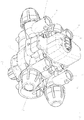
- the multiple nozzle body according to the 1 to 10 has the housing 1.
- the fastening means 2, with which the multiple nozzle body can be fastened to frame elements, distributor rods, etc., is arranged on the housing.
- the liquid to be dispensed is to be fed to the respective multiple nozzle body via this liquid line, which is arranged, for example, on a distributor linkage of an agricultural field sprayer.
- the liquid line 3 is connected to the branch line 5 arranged in the housing 1 in a branch region 4.
- the branch line 5 opens into the distributor space 6 arranged in the housing 1. From this distribution room 6 lead, according to the embodiment, four connecting lines 7, which form the extension of the branch line 5, to discharge lines 8 arranged in the housing 1, at the ends 9 of which discharge nozzles are arranged in a manner not shown by means of union nuts in a known manner.
- the connecting lines 7 are to be shut off in the area of the distributor space 6 by means of shut-off valves 11 having shut-off elements 10. Via these shut-off elements 10, the connecting lines 7 can optionally be connected to the feed line 5 and / or shut off from them.
- the shut-off elements 10 can be actuated via switchable actuating elements 12 and can thus be brought into the respective shut-off or flow position.
- the shut-off valves 11 each have a valve seat 13 arranged in the housing 1, to which a sealing ring 14 is assigned.
- the shut-off elements 10 are spherical, designed as spheres in the exemplary embodiment. If the balls 10 are in the valve seat 13, they cooperate with the sealing ring 14 of the valve seat 13 in this shut-off position.
- the balls 10 are assigned compression springs 15, by means of which they are pressed in the direction of the valve seat 13.
- the switchable actuating element 12 is disc-shaped and non-rotatably connected to a switching shaft 16 mounted in the housing 1.
- the actuating element 12 has a plurality of switching cams 17, 18, such as the 9 and 10 point to. According to the exemplary embodiment, the actuating element 12 has two switching cams 17, 18.
- the control shaft 16 of the actuating element 12 is connected in a rotationally fixed manner to a motorized actuating element 19, which is designed as an electric motor, and can thus be rotated about its axis of rotation by the motorized actuating element.
- One of the two switching cams 17 is designed such that it can only press a valve element designed as a ball 10 out of the valve seat 13, so that the flow to a connecting line 7 is released.
- the other of the two switching cams 18 is designed in such a way that it simultaneously shuts off two shut-off elements which are arranged as balls 10 and which flow into one another can move respective connecting lines 7 releasing position, that is, he can simultaneously press two valve elements designed as balls 10 out of their valve seats 13.
- the actuating element 11 with the two switching cams 19, 20 can be rotated into different positions, as is the case for some possible positions in the 9 and 10 is shown. As can be seen from this, depending on the switching position of the actuating element 12, the flow for none, one or more connecting lines 7 leading to the application nozzles application lines 8 are released. Thus, optionally, none, one or more connecting lines 7 and thus dispensing nozzles can be supplied in different combinations to the liquid to be dispensed.
- an intermediate wall 22 which projects into the free cross section of the liquid line 3 and has the end separating edge 21. Between the separating edge 21 and the line wall 23 of the liquid line 3 there is an opening 24 leading to the branch line 5. Furthermore, an additional opening 26 connecting the branch line 26 to the liquid line 3 is arranged on the end 25 of the intermediate wall 22 facing away from the end separating edge 21 . The opening 27 at the end separating edge 21 of the intermediate wall 22 is in flow connection with the further opening 24 at the end 25 of the intermediate wall 22.
- a further intermediate line 28, which is connected to the liquid line 3 and has an opening 24 to the liquid line 3, is thus assigned from the branch line 5 in the area of the shut-off elements 10.
- a guide wall 29 Arranged in the branch line 5 is a guide wall 29 which begins at the front separating edge 21 and leads to the respective flow nozzle of the nozzle body and guides the liquid flow.
- the guide wall 29 is designed as a bead 30 running on the side of the intermediate wall 22 facing away from the branch line 5 and extending in a curve in the direction of the dispensing nozzle.
- a gap region 32 through which the liquid flow can flow is arranged between the two side surfaces of the actuating disc 12 and the respectively adjacent housing walls.
- the openings 24 and 28 on the end face and the end of the intermediate wall 22 are connected to one another by the gap region 32 between the two side surfaces of the actuating disk 12 and the respectively adjacent housing walls.
- the liquid flow is fed to the dispensing nozzle arranged on the nozzle body.
- shut-off elements 10 Due to the arrangement of the shut-off elements 10 described above, they lie in the area of the liquid flow and are flowed around and / or washed around by a liquid flow which is greater than the quantity of liquid applied via the dispensing nozzle.
- the multiple nozzle body according to Fig. 11 differs in another embodiment of the arrangement of the intermediate wall 33 and the branch line 34 from the liquid line 3 and the additional connecting line 35 from the branch line 34 to the liquid line 3.
- the arrangement of the shut-off elements 10 via the actuating sheath 12 corresponds to the previous exemplary embodiment.
- the multiple nozzle body according to Fig. 12 differs by a different arrangement and position of the shut-off elements 10.
- the shut-off elements 10 are located directly within the liquid line 3 and here the liquid stream flows directly around and around them.
- the shut-off elements 10 are thus arranged in a region of the liquid flow which is larger than the amount of liquid applied via the dispensing nozzle.
- the shut-off elements 10 are actuated via the actuating disk 12, as described for the first exemplary embodiment.
Landscapes
- Engineering & Computer Science (AREA)
- General Engineering & Computer Science (AREA)
- Mechanical Engineering (AREA)
- Nozzles (AREA)
Description
Die Erfindung betrifft eine Flüssigkeitsleitung mit zugeordnetem Düsenkörper gemäß des Oberbegriffes des Patentanspruches 1.The invention relates to a liquid line with an associated nozzle body according to the preamble of patent claim 1.
Eine derartige Flüssigkeitsleitung mit zugeordnetem Düsenkörper ist in der
Der Erfindung liegt die Aufgabe zugrunde, in einfacher Weise zumindest bei der Absperrung der Zweigleitung durch die Absperrelemente eine behindernde Ablagerung von sich in der auszubringenden Flüssigkeit, wie beispielsweise Pflanzenschutzmittellösungen, befindliche Partikel, zu vermeiden.The object of the invention is to avoid, in a simple manner, at least when the branch line is shut off by the shut-off elements, an obstructive deposition of particles present in the liquid to be dispensed, such as, for example, crop protection agent solutions.
Diese Aufgabe wird erfindungsgemäß durch die Merkmale des Anspruchs 1 gelöst. Erfindungsgemäß ist unter anderem vorgesehen, dass die Absperrelemente in einem Bereich des Flüssigkeitsstromes liegen und von einem Flüssigkeitsstrom umströmt und/oder umspült werden, der größer als die über die Ausbringdüse ausgebrachte Flüssigkeitsmenge ist.This object is achieved by the features of claim 1. According to the invention, it is provided, inter alia, that the shut-off elements lie in a region of the liquid flow and are flowed around and / or washed around by a liquid flow which is larger than the quantity of liquid applied via the dispensing nozzle.
Infolge dieser Maßnahme wird die Strömung des Flüssigkeitsstromes im Bereich der Absperrelemente soweit erhöht, dass in allen Einsatzfällen immer eine ausreichende Strömung des Flüssigkeitsstromes im Absperrbereich herrscht, damit sich keine Partikel aus dem Flüssigkeitsstrom in die Funktionsweise des Absperrelementes behindernder Weise ablagern können. Hierbei können die Absperrelemente sogar bis in den Hauptflüssigkeitsstrom der Flüssigkeitsleitung hineinragen.As a result of this measure, the flow of the liquid flow in the area of the shut-off elements is increased to such an extent that there is always one in all applications there is sufficient flow of the liquid flow in the shut-off area so that no particles from the liquid flow can deposit in a manner which impedes the functioning of the shut-off element. The shut-off elements can even protrude into the main liquid flow of the liquid line.
Um sicherzustellen, dass immer eine ausreichend große Flüssigkeitsströmung im Absperrbereich herrscht, ist erfindungsgemäß vorgesehen, dass von der Abzweigleitung in dem Bereich der Absperrelemente eine weitere mit der Flüssigkeitsleitung verbundene und eine Öffnung zur Flüssigkeitsleitung aufweisende Zwischenleitung zugeordnet ist.In order to ensure that there is always a sufficiently large liquid flow in the shut-off area, it is provided according to the invention that from the branch line in the area of the shut-off elements a further intermediate line connected to the liquid line and having an opening to the liquid line is assigned.
Um einen ausreichend großen Flüssigkeitsstrom in sicherer Weise zu entfernt von dem Abzweigbereich angeordneten Absperrelementen zu erreichen, ist vorgesehen, dass in dem Abzweigungsbereich zumindest eine in den freien Querschnitt der Flüssigkeitsleitung hineinragende und zumindest eine stirnseitige Trennkante aufweisende Zwischenwand angeordnet ist, dass zwischen der zumindest einen Trennkante und der Leitungswand der Flüssigkeitsleitung zumindest eine zu der zumindest einen Abzweigleitung führende Öffnung sich befindet, dass auf dem der stirnseitigen Trennkante abgewandten Ende der Zwischenwand zumindest eine weitere die Abzweigleitung mit der Flüssigkeitsleitung verbindende Öffnung angeordnet ist. Hierdurch wird quasi ein Teilstrom durch die eine Trendkante aufweisende Zwischenwand vom Flüssigkeitsstrom abgeschnitten und zwangsweise in die Zweigleitung abgezweigt.In order to reliably achieve a sufficiently large liquid flow too far from the branch area, it is provided that at least one intermediate wall protruding into the free cross section of the liquid line and having at least one front separating edge is arranged in the branch area, between the at least one separating edge and the line wall of the liquid line is at least one opening leading to the at least one branch line, that at least one further opening connecting the branch line to the liquid line is arranged on the end of the intermediate wall facing away from the end separating edge. As a result, a partial flow is cut off from the liquid flow through the partition wall which has a trend edge and is forcibly branched off into the branch line.
Um eine gezielte Führung des Flüssigkeitsstromes in der Abzweigleitung zu der jeweiligen Ausbringdüse zu erreichen, ist vorgesehen, dass in der Abzweigleitung zumindest eine an der stirnseitigen Trennkante beginnende und zu der zu der jeweiligen Ausbringdüse des Düsenkörpers den Flüssigkeitsstrom leitende Führungswand angeordnet ist.In order to achieve a targeted guidance of the liquid flow in the branch line to the respective dispensing nozzle, it is provided that at least one guide wall starting at the separating edge at the end and leading to the respective dispensing nozzle of the nozzle body, the liquid flow is arranged in the branch line.
Damit der überschüssige Flüssigkeitsstrom, welcher nicht der Ausbringdüse zugeführt wird, wieder in die Flüssigkeitsleitung zurückleiten zu können, ist vorgesehen, dass zumindest eine Öffnung an der stirnseitigen Trennkante der Zwischenwand mit zumindest einer weiteren Öffnung an dem Ende der Zwischenwand in Durchflussverbindung steht. Hierdurch wird eine zwangsweise Umspülung der Absperrelemente sichergestellt.So that the excess liquid flow, which is not supplied to the dispensing nozzle, can be returned to the liquid line provided that at least one opening at the end separating edge of the intermediate wall with at least one further opening at the end of the The partition is in flow connection. In this way, a forced rinsing of the shut-off elements is ensured.
Bei einem als Mehrfachdüsenkörper ausgebildeten Düsenkörper, der über an einer Betätigungsscheibe angeordnete Schaltnocken betätigbare und den an dem Gehäuse des Mehrfachdüsenkörpers angeordnete Ausbringdüsen zugeordnete Absperrventile aufweist, ist vorgesehen, dass zwischen den beiden Seitenflächen der Betätigungsscheibe und den jeweils benachbarten Gehäusewandungen ein von dem Flüssigkeitsstrom durchströmbarer Spaltbereich angeordnet ist, dass die Öffnungen an der Stirnseite und dem Ende der Zwischenwand durch den Spaltbereich zwischen den beiden Seitenflächen der Betätigungsscheibe und den jeweils benachbarten Gehäusewandungen miteinander verbunden sind. Hierdurch wird sichergestellt, dass sich auch in dem Spaltbereich keine Partikel aus dem Flüssigkeitsstrom ablagern können.In the case of a nozzle body designed as a multiple nozzle body, which has shut-off valves which can be actuated via switching cams arranged on an actuating disc and which are assigned to the dispensing nozzles arranged on the housing of the multiple nozzle body, it is provided that a gap area through which the liquid flow can flow is arranged between the two side surfaces of the actuating disc and the respectively adjacent housing walls is that the openings on the end face and the end of the intermediate wall are connected to one another by the gap region between the two side surfaces of the actuating disk and the respectively adjacent housing walls. This ensures that no particles from the liquid flow can deposit in the gap area either.
Um den auszubringende Flüssigkeitsstrom in gezielter Weise zu der Ausbringdüse zuleiten, ist vorgesehen, dass durch die zumindest eine den Flüssigkeitsstrom leitende Führungswand der Flüssigkeitsstrom zu der zumindest einen an dem Düsenkörper angeordneten Ausbringdüse leitbar ist.In order to direct the liquid flow to be discharged to the dispensing nozzle in a targeted manner, it is provided that the liquid flow can be conducted to the at least one dispensing nozzle arranged on the nozzle body through the at least one guide wall guiding the liquid flow.
Bei einem Mehrfachdüsenkörper ist vorgesehen, dass die Führungswand als auf der der Abzweigleitung abgewandten Seite der Zwischenwand vorzugsweise kurvenartig verlaufend in Richtung der Ausbringdüse verlaufende Wulst ausgebildet ist. Durch die Wulst wird der Flüssigkeitsstrom aufgeteilt und der jeweiligen Ausbringdüse gezielt zugeleitet.In the case of a multiple nozzle body, it is provided that the guide wall is designed as a bead which, on the side of the intermediate wall facing away from the branch line, preferably extends in a curve-like manner in the direction of the dispensing nozzle. The liquid flow is divided by the bead and directed to the respective dispensing nozzle.
Weitere Einzelheiten der Erfindung sind der Beispielsbeschreibung und den Zeichnungen zu entnehmen. Hierbei zeigen
- Fig. 1
- den Mehrfachdüsenkörper in perspektivischer Ansicht,
- Fig. 2
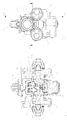
- den Mehrfachdüsenkörper in der Seitenansicht,
- Fig. 3
- den Mehrfachdüsenkörper im Bereich der Flüssigkeitsleitung in der Ansicht III - III,
- Fig. 4
- den Mehrfachdüsenkörper im Bereich der Flüssigkeitsleitung und im Abzweigbereich der Abzweigleitung in der Ansicht IV - IV,
- Fig. 5
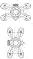
- den Mehrfachdüsenkörper in der Vorderansicht,
- Fig. 6
- den Mehrfachdüsenkörper in der Ansicht VI - VI,
- Fig. 7
- den Mehrfachdüsenkörper in der Seitenansicht,
- Fig. 8
- den Mehrfachdüsenkörper in der Ansicht VIII - VIII,
- Fig. 9
- den Mehrfachdüsenkörper in der Ansicht IX - IX,
- Fig. 10
- den Mehrfachdüsenkörper in der Ansicht X - X mit einer anderen Schaltstellung der Betätigungsscheibe,
- Fig. 11
- einen weiteren Mehrfachdüsenkörper in der Ansicht IV - IV und
- Fig. 12
- einen weiteren Mehrfachdüsenkörper in der Ansicht IV - IV.
- Fig. 1
- the multiple nozzle body in perspective view,
- Fig. 2
- the multiple nozzle body in side view,
- Fig. 3
- the multiple nozzle body in the area of the liquid line in view III - III,
- Fig. 4
- the multiple nozzle body in the area of the liquid line and in the branch area of the branch line in the view IV - IV,
- Fig. 5
- the multiple nozzle body in the front view,
- Fig. 6
- the multiple nozzle body in view VI - VI,
- Fig. 7
- the multiple nozzle body in side view,
- Fig. 8
- the multiple nozzle body in the view VIII - VIII,
- Fig. 9
- the multiple nozzle body in the view IX - IX,
- Fig. 10
- the multiple nozzle body in the view X - X with a different switching position of the actuating disc,
- Fig. 11
- a further multiple nozzle body in the view IV - IV and
- Fig. 12
- another multiple nozzle body in the view IV - IV.
Der Mehrfachdüsenkörper gemäß den
Die Flüssigkeitsleitung 3 ist mit der in dem Gehäuse 1 in einem Abzweigbereich 4 angeordneten Abzweigleitung 5 verbunden. Die Abzweigleitung 5 mündet in dem in dem Gehäuse 1 angeordneten Verteilerraum 6 aus. Von diesem Verteilerraum 6 führen, gemäß des Ausführungsbeispiels, vier Verbindungsleitungen 7, die die Verlängerung der Abzweigleitung 5 bilden, zu in dem Gehäuse 1 angeordneten Ausbringleitungen 8, an deren Enden 9 in nicht dargestellter Weise mittels Überwurfmuttern Ausbringdüsen in bekannter Weise angeordnet sind.The
Die Verbindungsleitungen 7 sind im Bereich des Verteilerraumes 6 mittels als Absperrelemente 10 aufweisende Absperrventile 11 abzusperren. Über diese Absperrelemente 10 sind die Verbindungsleitungen 7 mit der Zuleitung 5 wahlweise verbindbar und/oder ihr gegenüber absperrbar. Die Absperrelemente 10 sind über schaltbare Betätigungselemente 12 betätigbar und somit in die jeweilige Absperr- oder Durchflussposition zu bringen.The connecting
Die Absperrventile 11 weisen jeweils einen in dem Gehäuse 1 angeordneten Ventilsitz 13, dem jeweils ein Dichtring 14 zugeordnet ist, auf. Die Absperrelemente 10 sind kugelartig, im Ausführungsbeispiel als Kugeln ausgebildet. Wenn die Kugeln 10 sich im Ventilsitz 13 befinden, wirken sie in dieser Absperrstellung mit dem Dichtring 14 des Ventilsitzes 13 abdichtend zusammen. Den Kugeln 10 sind Druckfedern 15 zugeordnet, mittels welchem sie in Richtung des Ventilsitzes 13 gedrückt werden.The shut-off
Das schaltbare Betätigungselement 12 ist scheibenartig ausgebildet und drehfest mit einer in dem Gehäuse 1 gelagerten Schaltwelle 16 verbunden. Das Betätigungselement 12 weist mehrere Schaltnocken 17, 18, wie die
Einer der beiden Schaltnocken 17 ist so ausgestaltet, dass er nur ein als Kugel 10 ausgebildetes Ventilelement aus dem Ventilsitz 13 drücken kann, so dass der Durchfluss zu einer Verbindungsleitung 7 frei gegeben ist. Der andere der beiden Schaltnocken 18 ist so ausgestaltet, dass er zwei nebeneinander angeordnete als Kugeln 10 ausgebildete Absperrelemente gleichzeitig in eine den Durchfluss in die jeweiligen Verbindungsleitungen 7 freigebenden Stellung bewegen kann, das heißt, dass er gleichzeitig zwei als Kugeln 10 ausgebildete Ventilelemente aus ihren Ventilsitzen 13 drücken kann.One of the two switching
Das Betätigungselement 11 mit den beiden Schaltnocken 19, 20 ist in unterschiedliche Positionen verdrehbar, wie dies für einige mögliche Positionen in den
In dem Abzweigungsbereich 4 ist eine in den freien Querschnitt der Flüssigkeitsleitung 3 hineinragende und die stirnseitige Trennkante 21 aufweisende Zwischenwand 22 angeordnet. Zwischen der Trennkante 21 und der Leitungswand 23 der Flüssigkeitsleitung 3 befindet sich eine zu der Abzweigleitung 5 führende Öffnung 24. Des Weiteren ist auf dem der stirnseitigen Trennkante 21 abgewandten Ende 25 der Zwischenwand 22 eine weitere die Abzweigleitung 26 mit der Flüssigkeitsleitung 3 verbindende Öffnung 26 angeordnet. Die Öffnung 27 an der stirnseitigen Trennkante 21 der Zwischenwand 22 steht mit der weiteren Öffnung 24 an dem Ende 25 der Zwischenwand 22 in Durchflussverbindung. Somit ist von der Abzweigleitung 5 in dem Bereich der Absperrelemente 10 eine weitere mit der Flüssigkeitsleitung 3 verbundene und eine Öffnung 24 zur Flüssigkeitsleitung 3 aufweisende Zwischenleitung 28 zugeordnet.In the branching area 4 there is an
In der Abzweigleitung 5 ist eine an der stirnseitigen Trennkante 21 beginnende und zu der zu der jeweiligen Ausbringdüse des Düsenkörpers den Flüssigkeitsstrom leitende Führungswand 29 angeordnet. Die Führungswand 29 ist als auf der der Abzweigleitung 5 abgewandten Seite der Zwischenwand 22 kurvenartig verlaufend in Richtung der Ausbringdüse verlaufender Wulst 30 ausgebildet.Arranged in the
Zwischen den beiden Seitenflächen der Betätigungsscheibe 12 und den jeweils benachbarten Gehäusewandungen ist ein von dem Flüssigkeitsstrom durchströmbarer Spaltbereich 32 angeordnet. Die Öffnungen 24 und 28 an der Stirnseite und dem Ende der Zwischenwand 22 sind durch den Spaltbereich 32 zwischen den beiden Seitenflächen der Betätigungsscheibe 12 und den jeweils benachbarten Gehäusewandungen miteinander verbunden.A gap region 32 through which the liquid flow can flow is arranged between the two side surfaces of the
Durch die den Flüssigkeitsstrom leitende Führungswand 30 wird der Flüssigkeitsstrom zu den an dem Düsenkörper angeordneten Ausbringdüse zugeleitet.Through the
Durch die vorbeschriebene Anordnung der Absperrelemente 10 liegen diese im Bereich des Flüssigkeitsstromes und werden von einem Flüssigkeitsstrom umströmt und/oder umspült, der größer als die über die Ausbringdüse ausgebrachte Flüssigkeitsmenge ist.Due to the arrangement of the shut-off
Der Mehrfachdüsenkörper gemäß
Der Mehrfachdüsenkörper gemäß
Claims (7)
- Liquid line (3) having an associated nozzle body, wherein a branch line (5, 34) to the at least one dispensing nozzle of the nozzle body branches off in a branching region (4) from the liquid line (3), which liquid line has at least one line wall, wherein the branch line (5) is assigned a shut-off valve (11) having shut-off elements (10), wherein a partial quantity of the liquid stream (3) in the liquid line branches off into the branch line (5, 34) to the dispensing nozzle, characterized in that the shut-off elements (10) are situated in a region of the liquid stream and are flowed around and/or flushed around by a liquid stream which is greater than the quantity of liquid dispensed via the dispensing nozzle, and in that, from the branch line (5, 34), a further intermediate line (28, 35) which is connected to the liquid line (3) and has an opening to the liquid line (3) is assigned in the region of the shut-off elements (10) .
- Liquid line according to Claim 1, characterized in that at least one intermediate wall (22) projecting into the free cross section of the liquid line (3) and having at least one end-side separating edge (21) is arranged in the branching region (4), in that at least one opening leading to the at least one branch line (5) is situated between the at least one separating edge (21) and the line wall (23) of the liquid line (3), and in that at least one further opening (26) connecting the branch line (5) to the liquid line (3) is arranged at that end (25) of the intermediate wall (22) which faces away from the end-side separating edge (21).
- Liquid line according to Claim 2, characterized in that at least one guide wall (29), which begins at the end-side separating edge (21) and guides the liquid stream to the respective dispensing nozzle of the nozzle body, is arranged in the branch line (5) .
- Liquid line according to at least one of Claims 2 and/or 3, characterized in that at least one opening (27) at the end-side separating edge (21) of the intermediate wall (22) is in throughflow connection with at least one further opening (24) at the end (25) of the intermediate wall (22).
- Liquid line according to at least one of Claims 2 to 4, wherein the nozzle body is designed as a multiple-nozzle body and has shut-off valves which are actuable via switching cams arranged on an actuating disc and which are assigned to the dispensing nozzles arranged on the housing of the multiple-nozzle body, characterized in that a gap region (31) through which the liquid stream is able to flow is arranged between the two side surfaces of the actuating disc (12) and the in each case adjacent housing walls, and in that the openings at the end side and the end of the intermediate wall (22) are connected to one another by way of the gap region (31) between the two side surfaces of the actuating disc (12) and the in each case adjacent housing walls.
- Liquid line according to Claim 3, characterized in that, by way of the at least one guide wall (29) guiding the liquid stream, the liquid stream is able to be guided to the at least one dispensing nozzle arranged on the nozzle body.
- Liquid line according to Claim 3 or 6, characterized in that the guide wall (29) is formed as a bead (30) which runs in the direction of the dispensing nozzle so as to run preferably in a curved manner at that side of the intermediate wall (22) which faces away from the branch line (5, 34).
Applications Claiming Priority (1)
| Application Number | Priority Date | Filing Date | Title |
|---|---|---|---|
| DE102013104670.3A DE102013104670A1 (en) | 2013-05-07 | 2013-05-07 | Liquid line with associated nozzle body |
Publications (2)
| Publication Number | Publication Date |
|---|---|
| EP2801409A1 EP2801409A1 (en) | 2014-11-12 |
| EP2801409B1 true EP2801409B1 (en) | 2020-04-08 |
Family
ID=50884843
Family Applications (1)
| Application Number | Title | Priority Date | Filing Date |
|---|---|---|---|
| EP14401050.1A Active EP2801409B1 (en) | 2013-05-07 | 2014-05-05 | Liquid line with an associated nozzle body |
Country Status (3)
| Country | Link |
|---|---|
| EP (1) | EP2801409B1 (en) |
| DE (1) | DE102013104670A1 (en) |
| DK (1) | DK2801409T3 (en) |
Citations (3)
| Publication number | Priority date | Publication date | Assignee | Title |
|---|---|---|---|---|
| US4123006A (en) * | 1975-06-20 | 1978-10-31 | Osamu Shiina | Spray pipe for use in a pipe line |
| WO2007100247A2 (en) * | 2006-02-28 | 2007-09-07 | Color Wings B.V. | Spray head and device for printing or spraving textile materials |
| EP2002898A1 (en) * | 2007-06-14 | 2008-12-17 | J. Zimmer Maschinenbau Gesellschaft m.b.H. | Application device for applying a fluid onto a substrate with valve devices, method for cleaning the application device and valve device for application device |
Family Cites Families (3)
| Publication number | Priority date | Publication date | Assignee | Title |
|---|---|---|---|---|
| US2461617A (en) * | 1944-07-31 | 1949-02-15 | Carl F Gerlinger | Rotary ball valve |
| DE102008032933A1 (en) * | 2008-07-12 | 2010-01-14 | Sms Siemag Aktiengesellschaft | Apparatus and method for spraying pickling and / or rinsing liquid on a metallic material to be treated |
| DE102010036437A1 (en) | 2010-07-16 | 2012-01-19 | Amazonen-Werke H. Dreyer Gmbh & Co. Kg | Multiple nozzle body |
-
2013
- 2013-05-07 DE DE102013104670.3A patent/DE102013104670A1/en not_active Withdrawn
-
2014
- 2014-05-05 EP EP14401050.1A patent/EP2801409B1/en active Active
- 2014-05-05 DK DK14401050.1T patent/DK2801409T3/en active
Patent Citations (3)
| Publication number | Priority date | Publication date | Assignee | Title |
|---|---|---|---|---|
| US4123006A (en) * | 1975-06-20 | 1978-10-31 | Osamu Shiina | Spray pipe for use in a pipe line |
| WO2007100247A2 (en) * | 2006-02-28 | 2007-09-07 | Color Wings B.V. | Spray head and device for printing or spraving textile materials |
| EP2002898A1 (en) * | 2007-06-14 | 2008-12-17 | J. Zimmer Maschinenbau Gesellschaft m.b.H. | Application device for applying a fluid onto a substrate with valve devices, method for cleaning the application device and valve device for application device |
Also Published As
| Publication number | Publication date |
|---|---|
| DE102013104670A1 (en) | 2014-11-13 |
| EP2801409A1 (en) | 2014-11-12 |
| DK2801409T3 (en) | 2020-07-13 |
Similar Documents
| Publication | Publication Date | Title |
|---|---|---|
| EP2593235B1 (en) | Multiple nozzle head with multiport valve | |
| EP2462795B1 (en) | Pneumatic distribution machine | |
| DE2224320A1 (en) | Output head for irrigation systems or the like | |
| WO2002087779A1 (en) | Spray device for spraying liquids, especially for use in farming | |
| EP3706568A1 (en) | Spraying device and method | |
| DE102016218531A1 (en) | Distribution tower of a agricultural distributor | |
| EP3698614B1 (en) | Device for a distributor tower of an agricultural machine for applying a granular material with assistance of fluid flow, distributor tower and agricultural machine | |
| DE102007054673B4 (en) | Belt lubricating device and / or cleaning disinfection system | |
| WO2011160780A1 (en) | Switching apparatus for a fluid flow | |
| DE102018006660A1 (en) | Dosing unit for powder or particulate material to be distributed and distribution machine with such a dosing unit | |
| DE102006008612A1 (en) | Agricultural field sprayer | |
| DE102005038216A1 (en) | Distributor head for a pneumatic sowing machine receives seeds from a container via a feeder for compressed air to distribute over a deflector onto branching holes running into seed-discharge pipes | |
| EP3175923A1 (en) | Shower head | |
| EP2801409B1 (en) | Liquid line with an associated nozzle body | |
| EP3618891A1 (en) | Drip chamber arrangement for a medical infusion system | |
| EP2801408B1 (en) | Liquid line with an associated nozzle body | |
| EP2899147B1 (en) | Switch for bulk material | |
| DE102004056074A1 (en) | Jet outlet element for sanitary fittings | |
| DE102015101877A1 (en) | Lubricant distribution system and lubricant pump | |
| EP3643410B1 (en) | Nozzle body for an agricultural crop protection sprayer | |
| EP3542906A1 (en) | Nozzle assembly for a field sprayer | |
| EP2995184B1 (en) | Sowing machine | |
| EP3403497B1 (en) | Multiple nozzle body | |
| EP2801410B1 (en) | Multiple nozzle body | |
| WO2020089171A1 (en) | Injection nozzle |
Legal Events
| Date | Code | Title | Description |
|---|---|---|---|
| PUAI | Public reference made under article 153(3) epc to a published international application that has entered the european phase |
Free format text: ORIGINAL CODE: 0009012 |
|
| 17P | Request for examination filed |
Effective date: 20140505 |
|
| AK | Designated contracting states |
Kind code of ref document: A1 Designated state(s): AL AT BE BG CH CY CZ DE DK EE ES FI FR GB GR HR HU IE IS IT LI LT LU LV MC MK MT NL NO PL PT RO RS SE SI SK SM TR |
|
| AX | Request for extension of the european patent |
Extension state: BA ME |
|
| R17P | Request for examination filed (corrected) |
Effective date: 20150508 |
|
| RBV | Designated contracting states (corrected) |
Designated state(s): AL AT BE BG CH CY CZ DE DK EE ES FI FR GB GR HR HU IE IS IT LI LT LU LV MC MK MT NL NO PL PT RO RS SE SI SK SM TR |
|
| STAA | Information on the status of an ep patent application or granted ep patent |
Free format text: STATUS: EXAMINATION IS IN PROGRESS |
|
| 17Q | First examination report despatched |
Effective date: 20180618 |
|
| RIC1 | Information provided on ipc code assigned before grant |
Ipc: F16K 11/16 20060101ALI20190418BHEP Ipc: B05B 15/50 20180101ALI20190418BHEP Ipc: F16K 31/524 20060101ALI20190418BHEP Ipc: B05B 1/30 20060101ALI20190418BHEP Ipc: B05B 1/16 20060101AFI20190418BHEP Ipc: B05B 1/20 20060101ALI20190418BHEP |
|
| GRAP | Despatch of communication of intention to grant a patent |
Free format text: ORIGINAL CODE: EPIDOSNIGR1 |
|
| STAA | Information on the status of an ep patent application or granted ep patent |
Free format text: STATUS: GRANT OF PATENT IS INTENDED |
|
| INTG | Intention to grant announced |
Effective date: 20200115 |
|
| GRAS | Grant fee paid |
Free format text: ORIGINAL CODE: EPIDOSNIGR3 |
|
| GRAA | (expected) grant |
Free format text: ORIGINAL CODE: 0009210 |
|
| STAA | Information on the status of an ep patent application or granted ep patent |
Free format text: STATUS: THE PATENT HAS BEEN GRANTED |
|
| AK | Designated contracting states |
Kind code of ref document: B1 Designated state(s): AL AT BE BG CH CY CZ DE DK EE ES FI FR GB GR HR HU IE IS IT LI LT LU LV MC MK MT NL NO PL PT RO RS SE SI SK SM TR |
|
| REG | Reference to a national code |
Ref country code: CH Ref legal event code: EP Ref country code: AT Ref legal event code: REF Ref document number: 1253631 Country of ref document: AT Kind code of ref document: T Effective date: 20200415 |
|
| REG | Reference to a national code |
Ref country code: IE Ref legal event code: FG4D Free format text: LANGUAGE OF EP DOCUMENT: GERMAN |
|
| REG | Reference to a national code |
Ref country code: DE Ref legal event code: R096 Ref document number: 502014013936 Country of ref document: DE |
|
| REG | Reference to a national code |
Ref country code: NL Ref legal event code: FP |
|
| REG | Reference to a national code |
Ref country code: DK Ref legal event code: T3 Effective date: 20200708 |
|
| REG | Reference to a national code |
Ref country code: LT Ref legal event code: MG4D |
|
| PG25 | Lapsed in a contracting state [announced via postgrant information from national office to epo] |
Ref country code: PT Free format text: LAPSE BECAUSE OF FAILURE TO SUBMIT A TRANSLATION OF THE DESCRIPTION OR TO PAY THE FEE WITHIN THE PRESCRIBED TIME-LIMIT Effective date: 20200817 Ref country code: LT Free format text: LAPSE BECAUSE OF FAILURE TO SUBMIT A TRANSLATION OF THE DESCRIPTION OR TO PAY THE FEE WITHIN THE PRESCRIBED TIME-LIMIT Effective date: 20200408 Ref country code: NO Free format text: LAPSE BECAUSE OF FAILURE TO SUBMIT A TRANSLATION OF THE DESCRIPTION OR TO PAY THE FEE WITHIN THE PRESCRIBED TIME-LIMIT Effective date: 20200708 Ref country code: GR Free format text: LAPSE BECAUSE OF FAILURE TO SUBMIT A TRANSLATION OF THE DESCRIPTION OR TO PAY THE FEE WITHIN THE PRESCRIBED TIME-LIMIT Effective date: 20200709 Ref country code: IS Free format text: LAPSE BECAUSE OF FAILURE TO SUBMIT A TRANSLATION OF THE DESCRIPTION OR TO PAY THE FEE WITHIN THE PRESCRIBED TIME-LIMIT Effective date: 20200808 Ref country code: SE Free format text: LAPSE BECAUSE OF FAILURE TO SUBMIT A TRANSLATION OF THE DESCRIPTION OR TO PAY THE FEE WITHIN THE PRESCRIBED TIME-LIMIT Effective date: 20200408 Ref country code: FI Free format text: LAPSE BECAUSE OF FAILURE TO SUBMIT A TRANSLATION OF THE DESCRIPTION OR TO PAY THE FEE WITHIN THE PRESCRIBED TIME-LIMIT Effective date: 20200408 |
|
| PG25 | Lapsed in a contracting state [announced via postgrant information from national office to epo] |
Ref country code: HR Free format text: LAPSE BECAUSE OF FAILURE TO SUBMIT A TRANSLATION OF THE DESCRIPTION OR TO PAY THE FEE WITHIN THE PRESCRIBED TIME-LIMIT Effective date: 20200408 Ref country code: RS Free format text: LAPSE BECAUSE OF FAILURE TO SUBMIT A TRANSLATION OF THE DESCRIPTION OR TO PAY THE FEE WITHIN THE PRESCRIBED TIME-LIMIT Effective date: 20200408 Ref country code: BG Free format text: LAPSE BECAUSE OF FAILURE TO SUBMIT A TRANSLATION OF THE DESCRIPTION OR TO PAY THE FEE WITHIN THE PRESCRIBED TIME-LIMIT Effective date: 20200708 Ref country code: LV Free format text: LAPSE BECAUSE OF FAILURE TO SUBMIT A TRANSLATION OF THE DESCRIPTION OR TO PAY THE FEE WITHIN THE PRESCRIBED TIME-LIMIT Effective date: 20200408 |
|
| PG25 | Lapsed in a contracting state [announced via postgrant information from national office to epo] |
Ref country code: AL Free format text: LAPSE BECAUSE OF FAILURE TO SUBMIT A TRANSLATION OF THE DESCRIPTION OR TO PAY THE FEE WITHIN THE PRESCRIBED TIME-LIMIT Effective date: 20200408 |
|
| REG | Reference to a national code |
Ref country code: DE Ref legal event code: R097 Ref document number: 502014013936 Country of ref document: DE |
|
| PG25 | Lapsed in a contracting state [announced via postgrant information from national office to epo] |
Ref country code: MC Free format text: LAPSE BECAUSE OF FAILURE TO SUBMIT A TRANSLATION OF THE DESCRIPTION OR TO PAY THE FEE WITHIN THE PRESCRIBED TIME-LIMIT Effective date: 20200408 Ref country code: LI Free format text: LAPSE BECAUSE OF NON-PAYMENT OF DUE FEES Effective date: 20200531 Ref country code: SM Free format text: LAPSE BECAUSE OF FAILURE TO SUBMIT A TRANSLATION OF THE DESCRIPTION OR TO PAY THE FEE WITHIN THE PRESCRIBED TIME-LIMIT Effective date: 20200408 Ref country code: CH Free format text: LAPSE BECAUSE OF NON-PAYMENT OF DUE FEES Effective date: 20200531 Ref country code: EE Free format text: LAPSE BECAUSE OF FAILURE TO SUBMIT A TRANSLATION OF THE DESCRIPTION OR TO PAY THE FEE WITHIN THE PRESCRIBED TIME-LIMIT Effective date: 20200408 Ref country code: RO Free format text: LAPSE BECAUSE OF FAILURE TO SUBMIT A TRANSLATION OF THE DESCRIPTION OR TO PAY THE FEE WITHIN THE PRESCRIBED TIME-LIMIT Effective date: 20200408 Ref country code: CZ Free format text: LAPSE BECAUSE OF FAILURE TO SUBMIT A TRANSLATION OF THE DESCRIPTION OR TO PAY THE FEE WITHIN THE PRESCRIBED TIME-LIMIT Effective date: 20200408 Ref country code: ES Free format text: LAPSE BECAUSE OF FAILURE TO SUBMIT A TRANSLATION OF THE DESCRIPTION OR TO PAY THE FEE WITHIN THE PRESCRIBED TIME-LIMIT Effective date: 20200408 |
|
| PLBE | No opposition filed within time limit |
Free format text: ORIGINAL CODE: 0009261 |
|
| STAA | Information on the status of an ep patent application or granted ep patent |
Free format text: STATUS: NO OPPOSITION FILED WITHIN TIME LIMIT |
|
| PG25 | Lapsed in a contracting state [announced via postgrant information from national office to epo] |
Ref country code: SK Free format text: LAPSE BECAUSE OF FAILURE TO SUBMIT A TRANSLATION OF THE DESCRIPTION OR TO PAY THE FEE WITHIN THE PRESCRIBED TIME-LIMIT Effective date: 20200408 Ref country code: PL Free format text: LAPSE BECAUSE OF FAILURE TO SUBMIT A TRANSLATION OF THE DESCRIPTION OR TO PAY THE FEE WITHIN THE PRESCRIBED TIME-LIMIT Effective date: 20200408 |
|
| 26N | No opposition filed |
Effective date: 20210112 |
|
| REG | Reference to a national code |
Ref country code: BE Ref legal event code: MM Effective date: 20200531 |
|
| GBPC | Gb: european patent ceased through non-payment of renewal fee |
Effective date: 20200708 |
|
| PG25 | Lapsed in a contracting state [announced via postgrant information from national office to epo] |
Ref country code: LU Free format text: LAPSE BECAUSE OF NON-PAYMENT OF DUE FEES Effective date: 20200505 |
|
| PG25 | Lapsed in a contracting state [announced via postgrant information from national office to epo] |
Ref country code: IE Free format text: LAPSE BECAUSE OF NON-PAYMENT OF DUE FEES Effective date: 20200505 Ref country code: GB Free format text: LAPSE BECAUSE OF NON-PAYMENT OF DUE FEES Effective date: 20200708 |
|
| REG | Reference to a national code |
Ref country code: DE Ref legal event code: R081 Ref document number: 502014013936 Country of ref document: DE Owner name: AMAZONEN-WERKE H. DREYER SE & CO. KG, DE Free format text: FORMER OWNER: AMAZONEN-WERKE H. DREYER GMBH & CO. KG, 49205 HASBERGEN, DE |
|
| PG25 | Lapsed in a contracting state [announced via postgrant information from national office to epo] |
Ref country code: BE Free format text: LAPSE BECAUSE OF NON-PAYMENT OF DUE FEES Effective date: 20200531 Ref country code: SI Free format text: LAPSE BECAUSE OF FAILURE TO SUBMIT A TRANSLATION OF THE DESCRIPTION OR TO PAY THE FEE WITHIN THE PRESCRIBED TIME-LIMIT Effective date: 20200408 |
|
| REG | Reference to a national code |
Ref country code: AT Ref legal event code: MM01 Ref document number: 1253631 Country of ref document: AT Kind code of ref document: T Effective date: 20200505 |
|
| PG25 | Lapsed in a contracting state [announced via postgrant information from national office to epo] |
Ref country code: AT Free format text: LAPSE BECAUSE OF NON-PAYMENT OF DUE FEES Effective date: 20200505 |
|
| PG25 | Lapsed in a contracting state [announced via postgrant information from national office to epo] |
Ref country code: TR Free format text: LAPSE BECAUSE OF FAILURE TO SUBMIT A TRANSLATION OF THE DESCRIPTION OR TO PAY THE FEE WITHIN THE PRESCRIBED TIME-LIMIT Effective date: 20200408 Ref country code: MT Free format text: LAPSE BECAUSE OF FAILURE TO SUBMIT A TRANSLATION OF THE DESCRIPTION OR TO PAY THE FEE WITHIN THE PRESCRIBED TIME-LIMIT Effective date: 20200408 Ref country code: CY Free format text: LAPSE BECAUSE OF FAILURE TO SUBMIT A TRANSLATION OF THE DESCRIPTION OR TO PAY THE FEE WITHIN THE PRESCRIBED TIME-LIMIT Effective date: 20200408 |
|
| PG25 | Lapsed in a contracting state [announced via postgrant information from national office to epo] |
Ref country code: MK Free format text: LAPSE BECAUSE OF FAILURE TO SUBMIT A TRANSLATION OF THE DESCRIPTION OR TO PAY THE FEE WITHIN THE PRESCRIBED TIME-LIMIT Effective date: 20200408 |
|
| PGFP | Annual fee paid to national office [announced via postgrant information from national office to epo] |
Ref country code: FR Payment date: 20230309 Year of fee payment: 10 |
|
| P01 | Opt-out of the competence of the unified patent court (upc) registered |
Effective date: 20230523 |
|
| PGFP | Annual fee paid to national office [announced via postgrant information from national office to epo] |
Ref country code: IT Payment date: 20230412 Year of fee payment: 10 Ref country code: DK Payment date: 20230511 Year of fee payment: 10 Ref country code: DE Payment date: 20230307 Year of fee payment: 10 |
|
| PGFP | Annual fee paid to national office [announced via postgrant information from national office to epo] |
Ref country code: NL Payment date: 20240315 Year of fee payment: 11 |