EP2800860B1 - Déconnexion sans fil d'un train de tiges - Google Patents
Déconnexion sans fil d'un train de tiges Download PDFInfo
- Publication number
- EP2800860B1 EP2800860B1 EP13700792.8A EP13700792A EP2800860B1 EP 2800860 B1 EP2800860 B1 EP 2800860B1 EP 13700792 A EP13700792 A EP 13700792A EP 2800860 B1 EP2800860 B1 EP 2800860B1
- Authority
- EP
- European Patent Office
- Prior art keywords
- section
- drill string
- well bore
- uphole
- downhole
- Prior art date
- Legal status (The legal status is an assumption and is not a legal conclusion. Google has not performed a legal analysis and makes no representation as to the accuracy of the status listed.)
- Active
Links
- 238000000034 method Methods 0.000 claims description 59
- 239000012530 fluid Substances 0.000 claims description 47
- 239000004215 Carbon black (E152) Substances 0.000 claims description 6
- 230000015572 biosynthetic process Effects 0.000 claims description 6
- 229930195733 hydrocarbon Natural products 0.000 claims description 6
- 239000007787 solid Substances 0.000 claims description 6
- 125000001183 hydrocarbyl group Chemical group 0.000 claims description 5
- 230000005540 biological transmission Effects 0.000 claims description 4
- 238000003780 insertion Methods 0.000 claims 1
- 230000037431 insertion Effects 0.000 claims 1
- 230000008878 coupling Effects 0.000 description 16
- 238000010168 coupling process Methods 0.000 description 16
- 238000005859 coupling reaction Methods 0.000 description 16
- 238000005553 drilling Methods 0.000 description 15
- 238000012544 monitoring process Methods 0.000 description 9
- 238000004891 communication Methods 0.000 description 4
- 238000011084 recovery Methods 0.000 description 4
- 230000000694 effects Effects 0.000 description 3
- 230000005484 gravity Effects 0.000 description 3
- 230000000712 assembly Effects 0.000 description 2
- 238000000429 assembly Methods 0.000 description 2
- 235000019282 butylated hydroxyanisole Nutrition 0.000 description 2
- 238000004519 manufacturing process Methods 0.000 description 2
- 238000005259 measurement Methods 0.000 description 2
- 230000037361 pathway Effects 0.000 description 2
- 230000004044 response Effects 0.000 description 2
- 230000007704 transition Effects 0.000 description 2
- 102000004190 Enzymes Human genes 0.000 description 1
- 108090000790 Enzymes Proteins 0.000 description 1
- 238000009825 accumulation Methods 0.000 description 1
- 239000002253 acid Substances 0.000 description 1
- 230000001154 acute effect Effects 0.000 description 1
- 239000000853 adhesive Substances 0.000 description 1
- 230000001070 adhesive effect Effects 0.000 description 1
- 238000006243 chemical reaction Methods 0.000 description 1
- 238000007796 conventional method Methods 0.000 description 1
- 238000013480 data collection Methods 0.000 description 1
- 230000001934 delay Effects 0.000 description 1
- 238000013461 design Methods 0.000 description 1
- 238000007599 discharging Methods 0.000 description 1
- 230000007717 exclusion Effects 0.000 description 1
- 239000002360 explosive Substances 0.000 description 1
- 150000002430 hydrocarbons Chemical class 0.000 description 1
- 238000012423 maintenance Methods 0.000 description 1
- 230000007246 mechanism Effects 0.000 description 1
- 239000002184 metal Substances 0.000 description 1
- 238000012986 modification Methods 0.000 description 1
- 230000004048 modification Effects 0.000 description 1
- 239000003208 petroleum Substances 0.000 description 1
- 239000011148 porous material Substances 0.000 description 1
- 230000008569 process Effects 0.000 description 1
- 238000012545 processing Methods 0.000 description 1
- 239000004576 sand Substances 0.000 description 1
- 230000035939 shock Effects 0.000 description 1
- 239000003381 stabilizer Substances 0.000 description 1
- 238000012546 transfer Methods 0.000 description 1
- XLYOFNOQVPJJNP-UHFFFAOYSA-N water Substances O XLYOFNOQVPJJNP-UHFFFAOYSA-N 0.000 description 1
Images


Classifications
-
- E—FIXED CONSTRUCTIONS
- E21—EARTH DRILLING; MINING
- E21B—EARTH DRILLING, e.g. DEEP DRILLING; OBTAINING OIL, GAS, WATER, SOLUBLE OR MELTABLE MATERIALS OR A SLURRY OF MINERALS FROM WELLS
- E21B23/00—Apparatus for displacing, setting, locking, releasing, or removing tools, packers or the like in the boreholes or wells
-
- E—FIXED CONSTRUCTIONS
- E21—EARTH DRILLING; MINING
- E21B—EARTH DRILLING, e.g. DEEP DRILLING; OBTAINING OIL, GAS, WATER, SOLUBLE OR MELTABLE MATERIALS OR A SLURRY OF MINERALS FROM WELLS
- E21B17/00—Drilling rods or pipes; Flexible drill strings; Kellies; Drill collars; Sucker rods; Cables; Casings; Tubings
- E21B17/02—Couplings; joints
- E21B17/04—Couplings; joints between rod or the like and bit or between rod and rod or the like
- E21B17/06—Releasing-joints, e.g. safety joints
-
- E—FIXED CONSTRUCTIONS
- E21—EARTH DRILLING; MINING
- E21B—EARTH DRILLING, e.g. DEEP DRILLING; OBTAINING OIL, GAS, WATER, SOLUBLE OR MELTABLE MATERIALS OR A SLURRY OF MINERALS FROM WELLS
- E21B47/00—Survey of boreholes or wells
- E21B47/12—Means for transmitting measuring-signals or control signals from the well to the surface, or from the surface to the well, e.g. for logging while drilling
Definitions
- the field of invention relates to a drill string device and method of use. More specifically, the field relates to disconnecting and reconnecting a drill string and method of use.
- An in-line mechanical jar, hydraulic drilling jar or hydromechanical jar can provide an acute physical "shock" along the drill string axis.
- the force of the discharging jar suddenly shifts or pulls the drill string along the length of the well bore, dislodging it.
- Increasing drilling fluid circulation can provide fluid lift to the drill string and can erode solids that have blocked off drill string movement. "Pulsing" the drill string with rapid, successive rotational turns can shift obstructions and free the string.
- Such intervention can run from a few hours to weeks of drilling and completions time, with idle work crews, delays in scheduled production of hydrocarbon fluid and the loss of expensive downhole tools, including the drill bit, hundreds if not thousands of feet of drill pipe, collars and the borehole assemblies (BHA).
- BHA borehole assemblies
- Disconnection tools have a long history in the petroleum drilling service industry. Several types have come to prominence over the years, including those having shear-release, pressure-release and electrically controlled mechanisms. Shear and pressure disconnectors activate by either a build-up in pressure caused by introducing a restriction inside the throat of the tool, for example, a ball, dart or plug, or by using a redefined overfull or drill string turn sequence that initiates a mechanical release. Electrical disconnectors use wires from the surface through the drill string or by wireline or coiled tube. All of these disconnectors are "one-use": once they disconnect two sections of drill string they cannot be recombined.
- Disconnect tools have several inherent problems related to horizontal, ERW, multilateral and multi-tier well bore drilling.
- Conventional methods of freeing at least a portion of a stuck drill string are less appropriate in long-reaching horizontal well bores and in multi-lateral wells.
- the main problems are friction and gravity over the long horizontal leg.
- the designs of many tools are for operation in vertical environments and only over short distances - a few thousand feet.
- these tools and methods are very difficult if not impossible to use.
- Disconnector subs in downhole applications are described in US2008/041597 , US2011226482 and US2011/088903 .
- a disconnector drill string has an uphole section and a downhole section coupled together by a disconnection sub.
- the disconnector drill string has an operative length and an internal fluid conduit that extends along its operative length.
- the uphole section is positioned uphole of the downhole section along the operative length of the disconnector drill string.
- the disconnection sub is operable to receive wirelessly a pre-designated command signal.
- the disconnection sub is also operable to selectively couple the uphole section and the downhole section together.
- the disconnection sub is also operable to selectively uncouple the uphole section and the downhole section from one another.
- An embodiment of the disconnector drill string includes a borehole assembly (BHA) as part of the downhole section.
- the BHA is operable when it couples to the uphole section and is not operable when it does not couple to the uphole section.
- a method for using the disconnector drill string in a well bore includes the step of introducing the disconnector drill string into the well bore.
- the well bore is defined by a well bore wall extending from the surface into a hydrocarbon-bearing formation and contains a well bore fluid.
- the method of use also includes the step of transmitting wirelessly the pre-designated command signal to the disconnection sub such that the disconnection sub selectively operates to uncouple the uphole section of the disconnector drill string from the downhole section of the disconnector drill string. When this occurs, the internal fluid conduit of the disconnector drill string is severed.
- the method of use also includes the step of removing the uphole section of the disconnector drill string from the well bore. Upon removal of the uphole section, the disconnected downhole section of the disconnector drill string remains in the well bore.
- An embodiment of the method includes the step of introducing a second uphole section into the well bore.
- the second uphole section has a disconnection sub.
- a further embodiment of the method includes the step of wirelessly transmitting a pre-designated command signal to the disconnection sub to selectively couple the second uphole section to the downhole section.
- a second disconnector drill string forms having an internal fluid conduit along its operative length.
- a further embodiment of the method includes the step of operating the second disconnector drill string to extend the length of the horizontal length of the well bore.
- a further embodiment of the method includes the step of removing the second disconnector drill string from the well bore.
- An embodiment of the method includes the step of introducing a second uphole section into the well bore.
- the second uphole section includes downhole tool, a first disconnection sub and a second disconnection sub.
- a further embodiment of the method includes the steps of transmitting a pre-designated command signal to the first disconnection sub to couple the second uphole section to the downhole section and transmitting a pre-designated command signal to the second disconnection sub to uncouple the second uphole section from the downhole section. The combination of transmissions results in coupling the downhole tool to the downhole section.
- the segmented and modular nature of pipe, collars and tools allows configuration of the disconnector drill string to support other well bore maintenance activities.
- the disconnector drill string can provide support for installing casing, cementing operations, water jetting, circulating drilling mud and other fluids, injecting acid or enzymes into the well bore for mud cake treatment, data collection and fishing for broken or abandoned equipment in the well bore.
- the variety of tasks possible with the disconnector drill string is only limited by the time required to round-trip the disconnector drill string, including reconfiguration time; the tools available; the needs of operations and the imagination of those skilled in the art.
- Coupling together separate drill string sections is useful for performing several types of well bore activities, including fishing, swapping tools, and extending the reach of a drill string in horizontal, ERWs, multilateral, and multi-tier wells.
- the ability to easily disconnect and connect downhole portions of the drill string from uphole sections of the drill string expands operational flexibility.
- Temporary abandonment and recovery of the heavy, expensive and sometimes fragile assemblies and tools during horizontal, ERW, multilateral and multi-tier operation saves both time and money, and thereby improves operational reliability.
- Disconnecting easily and cleanly from a trapped or stuck section of drill string provides additional options for handling lost equipment and troubled well bores versus harsh and permanent disconnection.
- Locating disconnection subs downstring from a heavy drill string section permits active position management of the heavy components of a drill string. Uncoupling and removing the heavy portion of the drill string (that is, drill collars and HWDP) before those portions of the drill string enter the horizontal run of the well bore can reduce overall drill string friction. Round tripping the uphole section allows for reconfiguration of the string with lighter components that are to enter the horizontal run. Such reconfiguration and readjustments of the weighted portions of the drill string helps with running tools such as sand control screens, slotted liners and in performing complex completion operations where the drill string should not rotate.
- the coupling of a modified uphole section to the downhole section of the disconnector drill string forms a new drill string that is longer in reach than the original disconnector drill string.
- the coupling of the uphole section to the previously abandoned downhole section of drill string can render the equipment on the previously abandoned section operable.
- the abandoned section of drill string includes a borehole assembly
- establishing new control and power connections for the BHA provides the necessary means for freeing the drill string from the obstructions in the well bore holding it in place. This can prevent one of the most expensive components in the drill string - the BHA - from being lost.
- Disconnection subs can render the tool attachable to other objects, including immobile object, in the well bore.
- immobile well bore objects include previously abandoned portion of drill string and broken BHAs.
- Tools like whipstocks, which are channeled wedges typically made of metal, once secured in the well bore can expedite circumvention drilling around an obstruction that would otherwise require premediation.
- Disconnection subs can connect to the immobile object and disconnect from the delivering drill string.
- Figures 1-3 are general schematics of several embodiments of the disconnector drill string and their methods of use. Figures 1-3 and their description facilitate a better understanding of the disconnector drill string and its methods of use. In no way should the Figures limit or define the scope of the invention.
- Spatial terms describe the relative position of an object or a group of objects relative to another object or group of objects.
- the spatial relationships apply along vertical and horizontal axes.
- Orientation and relational words including “uphole” and “downhole”; “above” and “below”; “up” and “down” and other like terms are for descriptive convenience and are not limiting unless otherwise indicated.
- the "inclination angle" of a well bore is the measure of deviation in angle from true vertical from the perspective of traversing downward through the well bore from the surface.
- An angle of 0° degree downward is “true vertical”.
- An angle of 90° from true vertical is “true horizontal”.
- a "horizontale run”, “leg”, or “section” is a portion of the well bore where the inclination angle of the well bore is equal to or greater than 65° from true vertical, including values above true horizontal up to 115° from true vertical.
- a “horizontal well” is a well that has a well bore with a horizontal run for a portion of the well bore length. Horizontal wells have other portions of the well bore that are less than 65° in angle, including the vertical run that connects the well bore with the surface through the surface entry point.
- the "well bore length” is the length of the fluid flow pathway, representing the long dimension of the well bore versus its diameter or width, internal to the well bore from the surface entry point to the face of the well bore.
- An “extended reach well” is defined as a horizontal well having a well bore length along the horizontal run at least twice as long as the true vertical depth (TVD) of the well bore.
- Tripping describes the act of moving the drill string or segments of the drill string into and out of the well bore.
- Tripping in refers to introducing the drill string into the well bore.
- Tripping out refers to removing the drill string from the well bore.
- Relief tripping refers to removing the drill string from the well bore and then reintroducing the drill string into the well bore after a short interval of time. Modification to the drill string through the addition or subtraction of a tool or specialized equipment usually occurs when a drill string is being round-tripped.
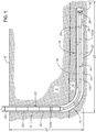
- Figure 1 shows well bore 2 as a space defined by well bore wall 4.
- Well bore 2 is a fluid pathway that extends from surface 6, through non-hydrocarbon bearing formation 8 into hydrocarbon-bearing formation 10.
- Well bore 2 has several sections, including vertical run 12, transition zone 14 and horizontal run 16.
- Horizontal run 16 extends in a generally horizontal direction from transition zone 14 until reaching the distal end of well bore 2, which is well bore face 18.
- Well bore 2 contains well bore fluid 20.
- Well bore 2 has horizontal run length 22 that is much longer than its total vertical depth (TVD) 24. Both horizontal run length 22 and TVD 24 are useful for determining the operative length of well bore 2.
- TVD total vertical depth
- FIG. 1 also shows disconnector drill string 30 previously introduced into well bore 2.
- Disconnector drill string 30 mainly comprises Drill pipes 32 and drill collars 33 couple to form the majority of disconnector drill string 30.
- Disconnector drill string 30 also includes borehole assembly (BHA) connector 34, BHA 36 and drill bit 38 proximate to well bore face 18. Connectors are also referred to as "subs" because they are much shorter than drill pipe and drill collars.
- BHA 36 can contain downhole motors, rotary steerable systems, jars, stabilizers, measurement while drilling (MWD) and logging while drilling (LWD) tools and sensors.
- MWD measurement while drilling
- LWD logging while drilling
- Disconnector drill string 30 has an internal fluid conduit (not shown) that permits fluid communication between surface 6 and well bore 2.
- the internal fluid conduit of disconnector drill string 30 is accessible at drill bit 38.
- the exterior surface of disconnector drill string 30 and well bore wall 4 define well bore annulus 40.
- Well bore fluid 20 circulates (represented by arrows 42) within well bore 2 through the interior fluid conduit (not shown) of disconnector drill string 30 and well bore annulus 40.
- disconnector drill string 30 couples to a wireless telemetry system.
- An operator monitoring system is in two-way signal communication with disconnector drill string 30 through the wireless telemetry system. Based upon its configuration, the operator monitoring system receives downhole condition data through the wireless telemetry system for human or computer interpretation, including conversion into borehole condition data.
- the wireless telemetry system provides the communication interface for receiving downhole condition information and transmitting pro-designated command signals to tools and equipment in well bore 2, including those on BHA 36 and along the operative length of disconnector drill string 30.
- Figure 1 also shows disconnector drill string 30 including disconnection sub 100 along its operative length.
- Disconnection sub 100 can have various physical configurations, including disconnection sub 100a for fitting two drill pipes 32 together and disconnection sub 100b for fitting between two drill collars 33.
- a disconnection sub can enhance the ability to free a portion of the drill string, reconfigure it and then attempt to free and extract the trapped portion from the well bore.
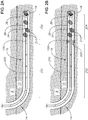
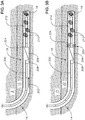
- FIG. 2A shows disconnector drill string 200 in well bore 2.
- Disconnector drill string 200 has disconnection sub 100 coupling uphole section 202 to downhole section 204.
- Debris 210 immobilizes disconnector drill string 200.
- Debris 210 is downhole of disconnection sub 100.
- Figure 2B shows disconnection sub 100 receiving a transmitted wireless pre-designated command signal (represented by inbound ellipses 220) from the surface (not shown).
- the wireless pre-designated command signal includes instructions for disconnection sub 100 to uncouple disconnector drill string 200.
- Disconnection sub 100 in response, uncouples uphole section 202 from downhole section 204 upon receipt of the pre-designated command signal.
- Figure 2C shows uphole section 202 of disconnector drill string 200 tripping out (arrow 230) of well bore 2.
- Downhole section 204 which includes BHA 36, remains in well bore 2, abandoned and inoperable.
- Figure 2D shows the introduction (arrow 250) of second uphole section 240, which includes second disconnection sub 242 and motor 244, into well bore 2.
- the introduction positions second disconnection sub 242 proximate to downhole section such that second disconnection sub 242 is operable to couple second uphole section 240 and downhole section 204.
- Figure 2E shows second disconnection sub 242 receiving (inbound ellipses 260) a wireless pre-designated command signal transmitted from the surface.
- the pre-designated command signal instructs second disconnection sub 242 to couple second uphole section 240 to downhole section 204 in well bore 2.
- Second disconnector drill string 270 with an internal fluid conduit along its operative length (not shown).
- Motor 244 is operable to provide power to drill bit 38 and BHA 36 upon coupling downhole section 204 to second uphole section 240 and introduction of fluid through the internal fluid conduit.
- Figure 2F shows second disconnector drill string 270 tripping out (arrow 280) from well bore 2 having its downhole section 204 freed from debris 210.
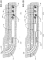
- Figures 3A-C show part of a method of securing a well bore tool to an immobilized object in the well bore.
- Figure 3A shows immobilized downhole section 310 in well bore 2.
- Disconnector drill string with well bore tool 300 introduces (arrow 302) well bore tool 306 into well bore 2, which couples to first disconnection sub 304 and second disconnection sub 308.
- the introduction of disconnector drill string with well bore tool 300 is such that first disconnection sub 304 is operable to couple well bore tool 306 to immobilized downhole section 310.
- Figure 3B shows first disconnection sub 304 receiving (inbound ellipses 320) a transmitted wireless pre-designated command signal from the surface that contains instructions to couple disconnector drill string with well bore tool 300 to immobilized downhole section 310 using first disconnection sub 304.
- Figure 3C shows second disconnection sub 308 receiving (inbound ellipses 330) a transmitted wireless pre-designated command signal from the surface that contains instructions to uncouple disconnector drill string with well bore tool 300 from immobilized downhole section 310.
- Well bore tool 306 affixes to immobilized downhole section 310.
- the combination of coupling and uncoupling steps forms an immobilized downhole section with well bore tool 336 and disconnector- drill string 334.
- Disconnector drill string 334 can trip out of well bore 2, leaving well bore tool 306 in position for later use.
- a surface monitoring and control system acts as an interface between the operator and a sub that is operable to receive pre-designated command signals.
- the surface monitoring and control system acts as the interface for the operator to designate actions for the subs to take in the form of command signals.
- the surface system converts operator instructions into pre-designated commands for the subs to perform.
- the surface monitoring system passes the pre-designated command to a wireless telemetry system for transmission into the well bore.
- the wireless telemetry system converts the pre-designated command into a wireless pre-designated command signal and transmits the pre-designed commande signal into the well bore such that the disconnection sub receives and acts upon the instructions.
- the surface monitoring and control system is in two-way data communications with the wireless telemetry system.
- the wireless telemetry system operates to receive the pre-designated command from the surface monitoring and control system, convert the pre-designated command into a pre-designated command signal, modulate the command signal for the intended recipient device and transmit wirelessly the pre-designated command signal downhole.
- the two systems work in the other way upon receiving a signal from a device downhole.
- the wireless telemetry controller is operable to receive a data or status signal conveyed from the sub downhole, convert the signal into data and pass the data to the surface monitoring and control system for automated or manual processing.
- the surface monitoring and control system displays information related to received downhole conditions and calculated borehole conditions into human-interpretable information for the operator.
- EM electromagnetic
- acoustic telemetry especially solid acoustic telemetry.
- an acoustic telemetry system can transmit a pre-designated command signal from the surface into the well bore while an EM telemetry system transmits a second, parallel signal downhole.
- a wireless telemetry system can transmit a pre-designated command signal via solid acoustic telemetry downhole while a sub transmits a data or status signal uphole using EM telemetry.
- the disconnector drill string includes at least one disconnection sub.
- the disconnection sub of the disconnector drill string is operable to receive a wireless pre-designated command signal.
- the receiving sub correlates the instructions contained in the pre-designated command signal with an associated function.
- the sub operates to perform the necessary steps to execute the associated function.
- a transmitted pre-designated command signal can instruct one or more subs to enter a non-dormant or "operational readiness'' state; another pre-designed command signal can instruct a sub to power down.
- a pre-designed command signal can request operational status information from one or more subs or to convey back uphole previously collected data.
- the pre-designated command signal can instruct more than one sub that normally operate independently of one another to act in concert in executing later-transmitted pre-designed command signals.
- the receiving device is operable to demodulate, decompress or decode the wireless signal.
- the disconnection sub can be located anywhere along the operative length of the disconnector drill string.
- the location of a disconnection sub can be between segments of drill pipes, collars and tools of similar or different gauge or type.
- the disconnector drill string can include multiple disconnection subs.
- the disconnector drill string has a disconnection sub that is operable to selectively decouple an uphole portion of the drill string from the downhole portion of the drill string.
- the disconnector drill string is operable to selective couple the uphole portion of a drill string to the downhole portion of a drill string, forming a disconnector drill string.
- An embodiment includes a disconnector drill string having more than one disconnection sub located along the operative length of the disconnector drill string.
- Each disconnection sub couples and decouples uphole and downhole sections relative to each disconnector while the disconnector drill string is in the well bore.
- the disconnection sub while coupling an uphole and downhole section together efficiently transfers rotational energy as an integral part of the drill string as well as conveys fluid through the disconnector drill string internal fluid conduit.
- the disconnection sub is operable to decouple an uphole section from a downhole section of drill string upon receipt of a pre-designated command signal associated with disconnection. Decoupling the disconnector drill string breaks the internal fluid conduit at the point of disconnection. Downhole equipment and tools, including the BHA, are inoperable without electrical, hydraulic or mud fluid flow from the surface. The unconnected downhole section is unable to function and cannot be removed from the well bore without mechanical assistance. The uphole section remains connected to the surface and is operable for removal and operation.
- the disconnection sub is operable to couple an uphole section of the drill string with the downhole section of the drill string upon receipt of a pre-designated command signal associated with connection. Coupling the uphole section of drill string with the downhole section of drill string forms a new disconnector drill string with an internal fluid conduit along the operative length of the formed drill string.
- Downhole equipment and tools, including the BHA, are enabled and operable with electrical, hydraulic or mud fluid flow from the surface upon coupling.
- An embodiment of the disconnector drill string includes a disconnection sub that affixes to the uphole section of the disconnector drill string.
- the disconnection sub affixes to a section of the disconnection sub through known connection means, including threaded, frictional, flange, latch or adhesive connection.
- connection means including threaded, frictional, flange, latch or adhesive connection.
- An embodiment of the disconnector drill string includes a disconnection sub affixed to the downhole section of the disconnector drill string. Upon decoupling, such a disconnection sub attached to the downhole section of the disconnector drill string loses power and control from the surface.
- An embodiment of the disconnector drill string includes a disconnection sub where a first portion of the disconnection sub affixes to the uphole section and a second portion affixes to the downhole section.
- a disconnection sub where a first portion of the disconnection sub affixes to the uphole section and a second portion affixes to the downhole section.
- Such a configuration is preferable for a matching or "key-lock" configuration to ensure proper orientation of the uphole and downhole sections upon coupling, where the first portion and the second portion couple together to form the coupling between the uphole section and the downhole section.
- the disconnector drill string which includes a disconnection sub, is useful for temporarily abandoning a portion of the drill string in the well bore and later reconnecting to the previously abandoned section for continued operations or recovery.
- the disconnector drill string includes an uphole section, which is the portion of the disconnector drill string uphole of the disconnection sub, and the downhole section, which is the potion downhole of the disconnection sub.
- the method includes introducing the disconnector drill string into a pre-formed well bore.
- the well bore wall defines the well bore and extends from the surface into the hydrocarbon-bearing formation.
- Well bore fluid fills the well bore.
- the introduction of the disconnector drill string forms a well bore annulus between the exterior of the disconnector drill string and the well bore wall.
- the method includes transmitting wirelessly a pre-designated command signal directed to a disconnection sub positioned in the well bore along the operative length of the disconnector drill string.
- An embodiment of the method includes transmitting the pre-designated command signal in response to a detected downhole condition.
- the surface wireless telemetry system transmits the pre-designated command signal wirelessly such that the wireless signal reaches the disconnection sub downhole.
- the disconnection sub Upon receiving the pre-designated command signal, the disconnection sub selectively operates to uncouple the uphole section from the downhole section.
- the uphole section of remains connected with the surface; the downhole section of the drill string does not. Separating the uphole section from the downhole section of the disconnector drill string severs the internal fluid conduit of the disconnector drill string. Decoupling the disconnector drill string renders downhole equipment and tools, including BHAs, inoperable. Downhole instruments and tools require some form of power and instruction from the surface to operate.
- the method includes tripping the uphole section of the drill string out of the well bore. Removing the uphole section from the downhole section abandons the downhole section in the well bore.
- the abandonment can be temporary or permanent.
- An embodiment of the method includes introducing a second uphole section of a disconnector drill string into the well bore such that the leading element (that is, the downhole end) of the second uphole section is proximate to the downhole section.
- the second uphole section tripped in can have a similar or different configuration than the uphole section tripped out of the well bore.
- the second uphole section also includes a fishing tool.
- the second uphole section includes a hydraulic motor.
- the second uphole section includes a well bore bypass tool.
- the second uphole section has a longer operable length than the uphole section tripped out.
- the second uphole section has a fewer number of drill collars at the same operable length than the uphole section tripped out.
- An embodiment of the method includes transmitting a second pre-designated command signal to the disconnection sub of the second uphole section such that second uphole section and the downhole section couple and form a second disconnector drill string. Coupling two separate drill string sections forms a new, second disconnector drill string.
- the second disconnector drill string has an internal fluid conduit along the length of the second disconnector drill string between the surface and the distal end of the downhole section.
- the coupling of the second uphole section and the downhole section renders equipment on the downhole section operable.
- the BHA upon re-establishing power and control with the surface, is operable to perform activities that require mudflow, including directing fluids, taking measurements and rotating the drill bit.
- the second disconnector drill string is operable to continue drilling operations as a fully functional drill string.
- An embodiment of the method includes introducing a fluid into the well bore through the internal fluid conduit of the second disconnector drill string.
- An embodiment of the method includes operating the second disconnector drill string such that the well bore debris in the well bore annulus releases it.
- An embodiment of the method includes operating the second disconnector drill string such that it extends the horizontal length of the well bore.
- An embodiment of the method includes tripping out the second disconnector drill string. The recovery of the second disconnector drill string occurs upon re-establishing fluid flow and functionality to the previously disconnected downhole section.
- An embodiment of the method includes introducing a second uphole section of a disconnector drill string into the well bore where that the leading element of the second uphole section is proximate to the downhole section.
- the leading element is a first disconnection sub.
- a downhole tool couples to the first disconnection sub and a second disconnection sub couples to the downhole tool uphole.
- transmitting a pre-designated command signal to the first disconnection sub of the second uphole section couples the second uphole section and the downhole section of the disconnector drill string.
- a fluid conduit forms along the length of the formed drill string.
- transmitting a pre-designated command signal to the second disconnection sub of the second uphole section decouples the downhole tool from the second uphole section, forming both a second uphole section without the downhole tool and a downhole section coupled with the downhole tool.
- the first disconnection sub secures the downhole tool to the downhole section.
- An embodiment of the method includes tripping out the second uphole section without the downhole tool.
- the downhole tool can be a well bore diversion tool, including a whipstock.
Claims (14)
- Procédé permettant d'utiliser un train de tiges de déconnexion dans un puits de forage, comprenant les étapes consistant à :introduire le train de tiges de déconnexion dans le puits de forage, dans lequel le train de tiges de déconnexion présente un raccord de déconnexion, un conduit de fluide interne, une longueur fonctionnelle, une première section haute et une section de fond de trou qui sont couplées ensemble grâce au raccord de déconnexion, la première section haute étant positionnée au-dessus de la section de fond de trou le long de la longueur fonctionnelle du train de tiges de déconnexion, et dans lequel le puits de forage est défini grâce à une paroi de puits de forage s'étendant à partir de la surface jusque dans une formation pétrolifère et contient un fluide de puits de forage ;transmettre sans fil un signal de commande prédéfini vers le raccord de déconnexion de telle manière que le raccord de déconnexion fonctionne de manière sélective pour découpler la première section haute du train de tiges de déconnexion par rapport à la section de fond de trou du train de tiges de déconnexion, ce qui coupe le conduit de fluide interne du train de tiges de déconnexion ; etretirer la première section haute du train de tiges de déconnexion hors du puits de forage de sorte que la section de fond de trou du train de tiges de déconnexion reste dans le puits de forage ; etcaractérisé par l'étape consistant àintroduire une deuxième section haute dans le puits de forage, dans lequel la deuxième section haute présente un raccord de déconnexion sur une extrémité distale de la deuxième section haute, de sorte que le raccord de déconnexion est positionné à proximité de la section de fond de trou.
- Procédé selon la revendication 1, dans lequel le puits de forage est un puits de forage horizontal.
- Procédé selon la revendication 1 ou 2, dans lequel la section de fond de trou du train de tiges de déconnexion comprend en outre un ensemble pour trou de forage, dans lequel l'ensemble pour trou de forage peut être utilisé pendant qu'il est couplé à la première section haute.
- Procédé selon l'une quelconque des revendications 1 à 3, dans lequel le signal de commande prédéfini est transmis en utilisant une télémétrie acoustique en milieu solide ou une télémétrie électromagnétique.
- Procédé selon l'une quelconque des revendications 1 à 4, dans lequel le raccord de déconnexion est situé dans une section non horizontale du puits de forage au moment de la transmission du signal de commande prédéfini.
- Procédé selon la revendication 1, dans lequel :(i) la deuxième section haute présente une configuration différente de celle de la première section haute retirée ; et/ou(ii) dans lequel la deuxième section haute comprend un moteur hydraulique ; et/ou(iii) dans lequel la deuxième section haute comprend un outil de repêchage ; et/ou(iv) dans lequel la deuxième section haute comprend un outil de dérivation de puits de forage ; et/ou(v) dans lequel la deuxième section haute présente une longueur fonctionnelle plus longue que la section haute retirée.
- Procédé selon l'une quelconque des revendications précédentes, dans lequel la deuxième section haute présente un nombre de masses-tiges inférieur à celui de la première section haute retirée.
- Procédé selon l'une quelconque des revendications précédentes, comprenant en outre l'étape consistant à transmettre sans fil un deuxième signal de commande prédéfini vers le raccord de déconnexion de sorte que le raccord de déconnexion fonctionne de manière sélective pour coupler la deuxième section haute à la section de fond de trou, ce qui forme un deuxième train de tiges de déconnexion, dans lequel le deuxième train de tiges de déconnexion présente un conduit de fluide interne pour sa longueur fonctionnelle.
- Procédé selon la revendication 8 :(i) dans lequel la section de fond de trou du deuxième train de tiges de déconnexion comprend en outre un ensemble pour trou de forage, dans lequel l'ensemble pour trou de forage peut être utilisé pendant qu'il est couplé à la deuxième section haute ; et/ou(ii) comprenant en outre l'étape consistant à introduire un fluide dans le puits de forage à travers le conduit de fluide interne du deuxième train de tiges de déconnexion ; et/ou(iii) comprenant en outre l'étape consistant à faire fonctionner le deuxième train de tiges de déconnexion pour enlever des débris en provenance d'un espace annulaire de puits de forage, dans lequel l'espace annulaire de puits de forage est défini comme étant l'espace situé entre une surface externe du deuxième train de tiges de déconnexion et la paroi de puits de forage ; et/ou(iv) comprenant en outre l'étape consistant à faire fonctionner le deuxième train de tiges de déconnexion pour étendre la longueur horizontale du puits de forage ; et/ou(v) comprenant en outre l'étape consistant à retirer le deuxième train de tiges de déconnexion hors du puits de forage.
- Procédé selon l'une quelconque des revendications 1 à 5, dans lequel la deuxième section haute comprend un premier raccord de déconnexion, un deuxième raccord de déconnexion et un outil de fond de trou, dans lequel le premier raccord de déconnexion et le deuxième raccord de déconnexion se couplent à des extrémités opposées de l'outil de fond de trou et le premier raccord de déconnexion est le raccord de déconnexion situé sur l'extrémité distale de la deuxième section haute.
- Procédé selon la revendication 10, comprenant en outre les étapes consistant à :transmettre sans fil un deuxième signal de commande prédéfini vers le premier raccord de déconnexion de sorte que le raccord de déconnexion fonctionne de manière sélective pour coupler la deuxième section haute à la section de fond de trou, ettransmettre sans fil un troisième signal de commande prédéfini vers le deuxième raccord de déconnexion de sorte que le deuxième raccord de déconnexion fonctionne de manière sélective pour découpler la deuxième section haute par rapport à la section de fond de trou,de sorte que l'outil de fond de trou se couple à la section de fond de trou et ne se couple pas à la deuxième section haute.
- Procédé selon la revendication 11, dans lequel l'outil de fond de trou est un outil de déviation de puits de forage.
- Train de tiges de déconnexion dans un puits comprenant une première section haute ; une section de fond de trou couplée ensemble par un raccord de déconnexion, dans lequel le train de tiges de déconnexion présente une longueur fonctionnelle et un conduit de fluide interne qui s'étend le long de sa longueur fonctionnelle, dans lequel la première section haute est positionnée au-dessus de la section de fond de trou le long de la longueur fonctionnelle, et dans lequel le raccord de déconnexion peut servir à recevoir sans fil un signal de commande prédéfini, afin de coupler ensemble de manière sélective la première section haute et la section de fond de trou, et afin de découpler de manière sélective la première section haute et la section de fond de trou l'une par rapport à l'autre de sorte que la première section haute peut être retirée du puits pendant que la section de fond de trou reste dans le puits ;
caractérisé par
une deuxième section haute avec un deuxième raccord de déconnexion situé sur une extrémité distale de la deuxième section haute, de sorte que le raccord de déconnexion est positionné à proximité de la section de fond de trou, la deuxième section haute permettant une insertion dans le puits après retrait de la première section haute hors du puits. - Train de tiges de déconnexion selon la revendication 13, dans lequel :(i) la section de fond de trou du train de tiges de déconnexion comprend en outre un ensemble pour trou de forage, dans lequel l'ensemble pour trou de forage peut être utilisé pendant qu'il est couplé à la première section haute du train de tiges de déconnexion ; et/ou(ii) dans lequel le raccord de déconnexion est fixé sur la première section haute du train de tiges de déconnexion ; et/ou(iii) dans lequel le train de tiges de déconnexion peut servir à recevoir le signal de commande prédéfini en utilisant une télémétrie acoustique en milieu solide.
Applications Claiming Priority (2)
| Application Number | Priority Date | Filing Date | Title |
|---|---|---|---|
| US201261582879P | 2012-01-04 | 2012-01-04 | |
| PCT/US2013/020221 WO2013103766A2 (fr) | 2012-01-04 | 2013-01-04 | Déconnexion sans fil d'un train de tiges |
Publications (2)
| Publication Number | Publication Date |
|---|---|
| EP2800860A2 EP2800860A2 (fr) | 2014-11-12 |
| EP2800860B1 true EP2800860B1 (fr) | 2017-09-20 |
Family
ID=47595061
Family Applications (1)
| Application Number | Title | Priority Date | Filing Date |
|---|---|---|---|
| EP13700792.8A Active EP2800860B1 (fr) | 2012-01-04 | 2013-01-04 | Déconnexion sans fil d'un train de tiges |
Country Status (5)
| Country | Link |
|---|---|
| US (1) | US9068415B2 (fr) |
| EP (1) | EP2800860B1 (fr) |
| CA (1) | CA2861621C (fr) |
| NO (1) | NO2800860T3 (fr) |
| WO (1) | WO2013103766A2 (fr) |
Families Citing this family (2)
| Publication number | Priority date | Publication date | Assignee | Title |
|---|---|---|---|---|
| EP2537058A1 (fr) * | 2010-02-21 | 2012-12-26 | Teraspan Networks Inc. | Composants d'installation pour réseau de guides d'onde optiques |
| US10533393B2 (en) | 2016-12-06 | 2020-01-14 | Saudi Arabian Oil Company | Modular thru-tubing subsurface completion unit |
Family Cites Families (19)
| Publication number | Priority date | Publication date | Assignee | Title |
|---|---|---|---|---|
| US2824718A (en) | 1954-03-18 | 1958-02-25 | Borg Warner | Mud decoupler |
| FR2101091A2 (en) | 1970-08-19 | 1972-03-31 | Geoservices | Automatic depth meter - for a borehole |
| NO180552C (no) | 1994-06-09 | 1997-05-07 | Bakke Oil Tools As | Hydraulisk utlösbar frakoplingsanordning |
| US5995449A (en) | 1995-10-20 | 1999-11-30 | Baker Hughes Inc. | Method and apparatus for improved communication in a wellbore utilizing acoustic signals |
| US5718291A (en) | 1996-03-07 | 1998-02-17 | Baker Hughes Incorporated | Downhole disconnect tool |
| US5967231A (en) | 1997-10-31 | 1999-10-19 | Halliburton Energy Services, Inc. | Plug release indication method |
| US6186249B1 (en) | 1998-01-14 | 2001-02-13 | Thor Bjornstad | Release equipment for a drill string |
| US6349767B2 (en) | 1998-05-13 | 2002-02-26 | Halliburton Energy Services, Inc. | Disconnect tool |
| US7086481B2 (en) * | 2002-10-11 | 2006-08-08 | Weatherford/Lamb | Wellbore isolation apparatus, and method for tripping pipe during underbalanced drilling |
| US7349833B2 (en) | 2004-10-01 | 2008-03-25 | Seiko Epson Corporation | 2D central difference level set projection method for ink-jet simulations |
| EP1915506B8 (fr) | 2005-08-02 | 2013-04-10 | Tesco Corporation | Procede d'extraction d'ensemble de fond de sondage d'une colonne de tubage |
| US9109439B2 (en) * | 2005-09-16 | 2015-08-18 | Intelliserv, Llc | Wellbore telemetry system and method |
| US7681642B2 (en) | 2006-08-21 | 2010-03-23 | Weatherford/Lamb, Inc. | Method for logging after drilling |
| US8016053B2 (en) | 2007-01-19 | 2011-09-13 | Halliburton Energy Services, Inc. | Drill bit configurations for parked-bit or through-the-bit-logging |
| FR2946998A1 (fr) * | 2009-06-17 | 2010-12-24 | Geoservices Equipements | Outil intermediaire de deconnexion destine a etre place dans une navette descendue dans un puits d'exploitation de fluide, navette et procede associes. |
| US8851175B2 (en) | 2009-10-20 | 2014-10-07 | Schlumberger Technology Corporation | Instrumented disconnecting tubular joint |
| US20110168389A1 (en) | 2010-01-08 | 2011-07-14 | Meijs Raymund J | Surface Controlled Downhole Shut-In Valve |
| WO2011097055A2 (fr) | 2010-02-02 | 2011-08-11 | Conocophillips Company | Résolveur d'agrégation-percolation multi-niveau pour simulations de réservoir de pétrole |
| US8393397B2 (en) * | 2010-03-17 | 2013-03-12 | Halliburton Energy Services, Inc. | Apparatus and method for separating a tubular string from a subsea well installation |
-
2013
- 2013-01-04 CA CA2861621A patent/CA2861621C/fr active Active
- 2013-01-04 EP EP13700792.8A patent/EP2800860B1/fr active Active
- 2013-01-04 NO NO13700792A patent/NO2800860T3/no unknown
- 2013-01-04 US US13/734,662 patent/US9068415B2/en active Active
- 2013-01-04 WO PCT/US2013/020221 patent/WO2013103766A2/fr active Application Filing
Non-Patent Citations (1)
| Title |
|---|
| None * |
Also Published As
| Publication number | Publication date |
|---|---|
| NO2800860T3 (fr) | 2018-02-17 |
| WO2013103766A2 (fr) | 2013-07-11 |
| EP2800860A2 (fr) | 2014-11-12 |
| US9068415B2 (en) | 2015-06-30 |
| CA2861621C (fr) | 2016-08-23 |
| US20130213640A1 (en) | 2013-08-22 |
| WO2013103766A3 (fr) | 2014-03-20 |
| CA2861621A1 (fr) | 2013-07-11 |
Similar Documents
| Publication | Publication Date | Title |
|---|---|---|
| US8347964B2 (en) | Releasing and recovering tool | |
| US8791832B2 (en) | Apparatus, system, and method for communicating while logging with wired drill pipe | |
| US10036234B2 (en) | Lateral wellbore completion apparatus and method | |
| CA2502591C (fr) | Appareil et methodes d'installation d'une ligne d'instrumentation dans un puits de forage | |
| EP2078820A2 (fr) | Forage et surveillance d'un puits avec un tubage enroulé utilisant un appareil traversant le trépan | |
| US10900305B2 (en) | Instrument line for insertion in a drill string of a drilling system | |
| US9976371B2 (en) | Pipe conveyed logging while fishing | |
| US10443325B2 (en) | Method and system for pipe conveyed logging | |
| US20010027879A1 (en) | Combined logging and drilling system | |
| EP2800860B1 (fr) | Déconnexion sans fil d'un train de tiges | |
| US11702932B2 (en) | Wired pipe with telemetry adapter | |
| US11952842B2 (en) | Sophisticated contour for downhole tools | |
| US20160298398A1 (en) | Multi-segment instrument line for instrument in drill string | |
| CA2593416A1 (fr) | Systeme et methode de telemetrie hybride pour puits de forage | |
| WO2017105402A1 (fr) | Mécanisme de déviation interactive de puits de forage |
Legal Events
| Date | Code | Title | Description |
|---|---|---|---|
| PUAI | Public reference made under article 153(3) epc to a published international application that has entered the european phase |
Free format text: ORIGINAL CODE: 0009012 |
|
| 17P | Request for examination filed |
Effective date: 20140619 |
|
| AK | Designated contracting states |
Kind code of ref document: A2 Designated state(s): AL AT BE BG CH CY CZ DE DK EE ES FI FR GB GR HR HU IE IS IT LI LT LU LV MC MK MT NL NO PL PT RO RS SE SI SK SM TR |
|
| DAX | Request for extension of the european patent (deleted) | ||
| GRAP | Despatch of communication of intention to grant a patent |
Free format text: ORIGINAL CODE: EPIDOSNIGR1 |
|
| INTG | Intention to grant announced |
Effective date: 20170531 |
|
| GRAS | Grant fee paid |
Free format text: ORIGINAL CODE: EPIDOSNIGR3 |
|
| GRAA | (expected) grant |
Free format text: ORIGINAL CODE: 0009210 |
|
| AK | Designated contracting states |
Kind code of ref document: B1 Designated state(s): AL AT BE BG CH CY CZ DE DK EE ES FI FR GB GR HR HU IE IS IT LI LT LU LV MC MK MT NL NO PL PT RO RS SE SI SK SM TR |
|
| REG | Reference to a national code |
Ref country code: GB Ref legal event code: FG4D |
|
| REG | Reference to a national code |
Ref country code: CH Ref legal event code: EP |
|
| REG | Reference to a national code |
Ref country code: AT Ref legal event code: REF Ref document number: 930281 Country of ref document: AT Kind code of ref document: T Effective date: 20171015 |
|
| REG | Reference to a national code |
Ref country code: IE Ref legal event code: FG4D |
|
| REG | Reference to a national code |
Ref country code: DE Ref legal event code: R096 Ref document number: 602013026814 Country of ref document: DE |
|
| REG | Reference to a national code |
Ref country code: FR Ref legal event code: PLFP Year of fee payment: 6 |
|
| REG | Reference to a national code |
Ref country code: NL Ref legal event code: MP Effective date: 20170920 |
|
| PG25 | Lapsed in a contracting state [announced via postgrant information from national office to epo] |
Ref country code: LT Free format text: LAPSE BECAUSE OF FAILURE TO SUBMIT A TRANSLATION OF THE DESCRIPTION OR TO PAY THE FEE WITHIN THE PRESCRIBED TIME-LIMIT Effective date: 20170920 Ref country code: FI Free format text: LAPSE BECAUSE OF FAILURE TO SUBMIT A TRANSLATION OF THE DESCRIPTION OR TO PAY THE FEE WITHIN THE PRESCRIBED TIME-LIMIT Effective date: 20170920 Ref country code: HR Free format text: LAPSE BECAUSE OF FAILURE TO SUBMIT A TRANSLATION OF THE DESCRIPTION OR TO PAY THE FEE WITHIN THE PRESCRIBED TIME-LIMIT Effective date: 20170920 Ref country code: SE Free format text: LAPSE BECAUSE OF FAILURE TO SUBMIT A TRANSLATION OF THE DESCRIPTION OR TO PAY THE FEE WITHIN THE PRESCRIBED TIME-LIMIT Effective date: 20170920 |
|
| REG | Reference to a national code |
Ref country code: LT Ref legal event code: MG4D |
|
| REG | Reference to a national code |
Ref country code: AT Ref legal event code: MK05 Ref document number: 930281 Country of ref document: AT Kind code of ref document: T Effective date: 20170920 |
|
| REG | Reference to a national code |
Ref country code: NO Ref legal event code: T2 Effective date: 20170920 |
|
| PG25 | Lapsed in a contracting state [announced via postgrant information from national office to epo] |
Ref country code: BG Free format text: LAPSE BECAUSE OF FAILURE TO SUBMIT A TRANSLATION OF THE DESCRIPTION OR TO PAY THE FEE WITHIN THE PRESCRIBED TIME-LIMIT Effective date: 20171220 Ref country code: RS Free format text: LAPSE BECAUSE OF FAILURE TO SUBMIT A TRANSLATION OF THE DESCRIPTION OR TO PAY THE FEE WITHIN THE PRESCRIBED TIME-LIMIT Effective date: 20170920 Ref country code: GR Free format text: LAPSE BECAUSE OF FAILURE TO SUBMIT A TRANSLATION OF THE DESCRIPTION OR TO PAY THE FEE WITHIN THE PRESCRIBED TIME-LIMIT Effective date: 20171221 Ref country code: LV Free format text: LAPSE BECAUSE OF FAILURE TO SUBMIT A TRANSLATION OF THE DESCRIPTION OR TO PAY THE FEE WITHIN THE PRESCRIBED TIME-LIMIT Effective date: 20170920 |
|
| PG25 | Lapsed in a contracting state [announced via postgrant information from national office to epo] |
Ref country code: NL Free format text: LAPSE BECAUSE OF FAILURE TO SUBMIT A TRANSLATION OF THE DESCRIPTION OR TO PAY THE FEE WITHIN THE PRESCRIBED TIME-LIMIT Effective date: 20170920 |
|
| PG25 | Lapsed in a contracting state [announced via postgrant information from national office to epo] |
Ref country code: PL Free format text: LAPSE BECAUSE OF FAILURE TO SUBMIT A TRANSLATION OF THE DESCRIPTION OR TO PAY THE FEE WITHIN THE PRESCRIBED TIME-LIMIT Effective date: 20170920 Ref country code: CZ Free format text: LAPSE BECAUSE OF FAILURE TO SUBMIT A TRANSLATION OF THE DESCRIPTION OR TO PAY THE FEE WITHIN THE PRESCRIBED TIME-LIMIT Effective date: 20170920 Ref country code: ES Free format text: LAPSE BECAUSE OF FAILURE TO SUBMIT A TRANSLATION OF THE DESCRIPTION OR TO PAY THE FEE WITHIN THE PRESCRIBED TIME-LIMIT Effective date: 20170920 Ref country code: RO Free format text: LAPSE BECAUSE OF FAILURE TO SUBMIT A TRANSLATION OF THE DESCRIPTION OR TO PAY THE FEE WITHIN THE PRESCRIBED TIME-LIMIT Effective date: 20170920 |
|
| PG25 | Lapsed in a contracting state [announced via postgrant information from national office to epo] |
Ref country code: IT Free format text: LAPSE BECAUSE OF FAILURE TO SUBMIT A TRANSLATION OF THE DESCRIPTION OR TO PAY THE FEE WITHIN THE PRESCRIBED TIME-LIMIT Effective date: 20170920 Ref country code: IS Free format text: LAPSE BECAUSE OF FAILURE TO SUBMIT A TRANSLATION OF THE DESCRIPTION OR TO PAY THE FEE WITHIN THE PRESCRIBED TIME-LIMIT Effective date: 20180120 Ref country code: SM Free format text: LAPSE BECAUSE OF FAILURE TO SUBMIT A TRANSLATION OF THE DESCRIPTION OR TO PAY THE FEE WITHIN THE PRESCRIBED TIME-LIMIT Effective date: 20170920 Ref country code: SK Free format text: LAPSE BECAUSE OF FAILURE TO SUBMIT A TRANSLATION OF THE DESCRIPTION OR TO PAY THE FEE WITHIN THE PRESCRIBED TIME-LIMIT Effective date: 20170920 Ref country code: EE Free format text: LAPSE BECAUSE OF FAILURE TO SUBMIT A TRANSLATION OF THE DESCRIPTION OR TO PAY THE FEE WITHIN THE PRESCRIBED TIME-LIMIT Effective date: 20170920 Ref country code: AT Free format text: LAPSE BECAUSE OF FAILURE TO SUBMIT A TRANSLATION OF THE DESCRIPTION OR TO PAY THE FEE WITHIN THE PRESCRIBED TIME-LIMIT Effective date: 20170920 |
|
| REG | Reference to a national code |
Ref country code: DE Ref legal event code: R097 Ref document number: 602013026814 Country of ref document: DE |
|
| PLBE | No opposition filed within time limit |
Free format text: ORIGINAL CODE: 0009261 |
|
| STAA | Information on the status of an ep patent application or granted ep patent |
Free format text: STATUS: NO OPPOSITION FILED WITHIN TIME LIMIT |
|
| PG25 | Lapsed in a contracting state [announced via postgrant information from national office to epo] |
Ref country code: DK Free format text: LAPSE BECAUSE OF FAILURE TO SUBMIT A TRANSLATION OF THE DESCRIPTION OR TO PAY THE FEE WITHIN THE PRESCRIBED TIME-LIMIT Effective date: 20170920 |
|
| 26N | No opposition filed |
Effective date: 20180621 |
|
| REG | Reference to a national code |
Ref country code: CH Ref legal event code: PL |
|
| PG25 | Lapsed in a contracting state [announced via postgrant information from national office to epo] |
Ref country code: LU Free format text: LAPSE BECAUSE OF NON-PAYMENT OF DUE FEES Effective date: 20180104 |
|
| REG | Reference to a national code |
Ref country code: IE Ref legal event code: MM4A |
|
| REG | Reference to a national code |
Ref country code: BE Ref legal event code: MM Effective date: 20180131 |
|
| PG25 | Lapsed in a contracting state [announced via postgrant information from national office to epo] |
Ref country code: SI Free format text: LAPSE BECAUSE OF FAILURE TO SUBMIT A TRANSLATION OF THE DESCRIPTION OR TO PAY THE FEE WITHIN THE PRESCRIBED TIME-LIMIT Effective date: 20170920 Ref country code: CH Free format text: LAPSE BECAUSE OF NON-PAYMENT OF DUE FEES Effective date: 20180131 Ref country code: LI Free format text: LAPSE BECAUSE OF NON-PAYMENT OF DUE FEES Effective date: 20180131 Ref country code: BE Free format text: LAPSE BECAUSE OF NON-PAYMENT OF DUE FEES Effective date: 20180131 |
|
| PG25 | Lapsed in a contracting state [announced via postgrant information from national office to epo] |
Ref country code: IE Free format text: LAPSE BECAUSE OF NON-PAYMENT OF DUE FEES Effective date: 20180104 |
|
| PG25 | Lapsed in a contracting state [announced via postgrant information from national office to epo] |
Ref country code: MC Free format text: LAPSE BECAUSE OF FAILURE TO SUBMIT A TRANSLATION OF THE DESCRIPTION OR TO PAY THE FEE WITHIN THE PRESCRIBED TIME-LIMIT Effective date: 20170920 |
|
| PG25 | Lapsed in a contracting state [announced via postgrant information from national office to epo] |
Ref country code: MT Free format text: LAPSE BECAUSE OF NON-PAYMENT OF DUE FEES Effective date: 20180104 |
|
| PG25 | Lapsed in a contracting state [announced via postgrant information from national office to epo] |
Ref country code: TR Free format text: LAPSE BECAUSE OF FAILURE TO SUBMIT A TRANSLATION OF THE DESCRIPTION OR TO PAY THE FEE WITHIN THE PRESCRIBED TIME-LIMIT Effective date: 20170920 |
|
| PG25 | Lapsed in a contracting state [announced via postgrant information from national office to epo] |
Ref country code: HU Free format text: LAPSE BECAUSE OF FAILURE TO SUBMIT A TRANSLATION OF THE DESCRIPTION OR TO PAY THE FEE WITHIN THE PRESCRIBED TIME-LIMIT; INVALID AB INITIO Effective date: 20130104 Ref country code: PT Free format text: LAPSE BECAUSE OF FAILURE TO SUBMIT A TRANSLATION OF THE DESCRIPTION OR TO PAY THE FEE WITHIN THE PRESCRIBED TIME-LIMIT Effective date: 20170920 |
|
| PG25 | Lapsed in a contracting state [announced via postgrant information from national office to epo] |
Ref country code: CY Free format text: LAPSE BECAUSE OF FAILURE TO SUBMIT A TRANSLATION OF THE DESCRIPTION OR TO PAY THE FEE WITHIN THE PRESCRIBED TIME-LIMIT Effective date: 20170920 Ref country code: MK Free format text: LAPSE BECAUSE OF NON-PAYMENT OF DUE FEES Effective date: 20170920 |
|
| PG25 | Lapsed in a contracting state [announced via postgrant information from national office to epo] |
Ref country code: AL Free format text: LAPSE BECAUSE OF FAILURE TO SUBMIT A TRANSLATION OF THE DESCRIPTION OR TO PAY THE FEE WITHIN THE PRESCRIBED TIME-LIMIT Effective date: 20170920 |
|
| PGFP | Annual fee paid to national office [announced via postgrant information from national office to epo] |
Ref country code: DE Payment date: 20211230 Year of fee payment: 10 |
|
| PGFP | Annual fee paid to national office [announced via postgrant information from national office to epo] |
Ref country code: FR Payment date: 20220118 Year of fee payment: 10 |
|
| PGFP | Annual fee paid to national office [announced via postgrant information from national office to epo] |
Ref country code: NO Payment date: 20230110 Year of fee payment: 11 |
|
| PGFP | Annual fee paid to national office [announced via postgrant information from national office to epo] |
Ref country code: GB Payment date: 20230105 Year of fee payment: 11 |
|
| P01 | Opt-out of the competence of the unified patent court (upc) registered |
Effective date: 20230526 |
|
| REG | Reference to a national code |
Ref country code: DE Ref legal event code: R119 Ref document number: 602013026814 Country of ref document: DE |
|
| PG25 | Lapsed in a contracting state [announced via postgrant information from national office to epo] |
Ref country code: DE Free format text: LAPSE BECAUSE OF NON-PAYMENT OF DUE FEES Effective date: 20230801 |
|
| PG25 | Lapsed in a contracting state [announced via postgrant information from national office to epo] |
Ref country code: FR Free format text: LAPSE BECAUSE OF NON-PAYMENT OF DUE FEES Effective date: 20230131 |