EP2800331B1 - Eingabe-lag-schätzung für wi-fi-anzeigesenken - Google Patents
Eingabe-lag-schätzung für wi-fi-anzeigesenken Download PDFInfo
- Publication number
- EP2800331B1 EP2800331B1 EP13166511.9A EP13166511A EP2800331B1 EP 2800331 B1 EP2800331 B1 EP 2800331B1 EP 13166511 A EP13166511 A EP 13166511A EP 2800331 B1 EP2800331 B1 EP 2800331B1
- Authority
- EP
- European Patent Office
- Prior art keywords
- sink device
- input
- display
- data
- sink
- Prior art date
- Legal status (The legal status is an assumption and is not a legal conclusion. Google has not performed a legal analysis and makes no representation as to the accuracy of the status listed.)
- Active
Links
Images



Classifications
-
- H—ELECTRICITY
- H04—ELECTRIC COMMUNICATION TECHNIQUE
- H04L—TRANSMISSION OF DIGITAL INFORMATION, e.g. TELEGRAPHIC COMMUNICATION
- H04L65/00—Network arrangements, protocols or services for supporting real-time applications in data packet communication
- H04L65/80—Responding to QoS
-
- H—ELECTRICITY
- H04—ELECTRIC COMMUNICATION TECHNIQUE
- H04L—TRANSMISSION OF DIGITAL INFORMATION, e.g. TELEGRAPHIC COMMUNICATION
- H04L65/00—Network arrangements, protocols or services for supporting real-time applications in data packet communication
- H04L65/60—Network streaming of media packets
- H04L65/75—Media network packet handling
- H04L65/762—Media network packet handling at the source
-
- H—ELECTRICITY
- H04—ELECTRIC COMMUNICATION TECHNIQUE
- H04N—PICTORIAL COMMUNICATION, e.g. TELEVISION
- H04N21/00—Selective content distribution, e.g. interactive television or video on demand [VOD]
- H04N21/20—Servers specifically adapted for the distribution of content, e.g. VOD servers; Operations thereof
- H04N21/23—Processing of content or additional data; Elementary server operations; Server middleware
- H04N21/234—Processing of video elementary streams, e.g. splicing of video streams or manipulating encoded video stream scene graphs
- H04N21/2343—Processing of video elementary streams, e.g. splicing of video streams or manipulating encoded video stream scene graphs involving reformatting operations of video signals for distribution or compliance with end-user requests or end-user device requirements
-
- H—ELECTRICITY
- H04—ELECTRIC COMMUNICATION TECHNIQUE
- H04N—PICTORIAL COMMUNICATION, e.g. TELEVISION
- H04N21/00—Selective content distribution, e.g. interactive television or video on demand [VOD]
- H04N21/20—Servers specifically adapted for the distribution of content, e.g. VOD servers; Operations thereof
- H04N21/25—Management operations performed by the server for facilitating the content distribution or administrating data related to end-users or client devices, e.g. end-user or client device authentication, learning user preferences for recommending movies
- H04N21/266—Channel or content management, e.g. generation and management of keys and entitlement messages in a conditional access system, merging a VOD unicast channel into a multicast channel
- H04N21/2662—Controlling the complexity of the video stream, e.g. by scaling the resolution or bitrate of the video stream based on the client capabilities
Definitions
- This specification relates generally to mobile devices and display systems, and more particularly to a method and apparatus for estimating input lag in Wi-Fi display systems.
- Wi-Fi Alliance has developed the MiracastTM standard, which uses Wi-Fi DirectTM interconnect supported devices without the need for a wireless access point.
- a real-time digital video screen capture from the source device is streamed via a WLAN (wireless local area network) for display via the sink device.
- a WLAN wireless local area network
- the content in the display buffer of the source device is in raw format (e.g. YUV colour space)
- the content must be compressed by an encoder (e.g. x264 encoder), taking into account the display device capabilities and network conditions in order to optimize transmission over the Wi-Fi interface.
- the display device (sink) receives the content, decodes it, and then displays the content.
- the compression introduced by encoding comes at the expense of image quality and/or latency.
- a minimum level of video quality must be provided.
- the output bit rate can be constrained using VBV (video buffer verifier) encoding, and encoder latency can be adjusted by varying the number of frames held by the x264 internal buffer.
- VBV video buffer verifier
- the required level of compression is dictated by the type and quality of the WLAN link, including supported rates and network conditions. For example, a 2x2 spatial multiplexing WLAN link provides an over-the-air (OTA) throughput of 130Mbps whereas a 1x1 WLAN link provides only 65Mbps.
- OTA over-the-air
- the latency requirement of the encoder is an integrant of the end-to-end latency (or glass-to-glass latency, which captures the time elapsed between the first pixel appearing on the source device and appearing on the sink device).
- the latency requirement dictates the class of supported applications over a given link. For example, a 100msec end-to-end latency budget may be sufficient to support a web browsing application whereas heavy interactive gaming may require a less than 50msec end-to-end budget.
- a significant portion of the end-to-end latency budget may be consumed by the input lag of the sink device, which is defined as the difference between the time that a signal is input into the sink device and the time that it is shown by the display.
- This input lag time has been measured as high as 68ms or the equivalent of 3- 4 frames on a 60 Hz display.
- the greater the input lag of the sink device the less compression that can be provided to the signal. Since the input lag is often unknown, it is customary to assume a conservative input lag contribution to the end-to-end latency when choosing the compression level during source encoding.
- the WFA maintains a current list of Miracast Certified devices for which the input lag is known. Therefore, in some implementations the input lag is stored as part of the extended display identification data message (display_edid), and can be used in calculating the level of compression to be applied at the source device for a particular application. However, there are many implementations where this information is not known.
- U.S. Patent Publication No. 2005/0210515 discloses a server system for performing moving picture data communication with a client device over a wireless network, and an operating method thereof.
- a server device compresses the moving picture data received from an external medium at a variably controlled compression rate according to transmission bandwidth of the current wireless network and an image quality level set by a user in response to a request of the client device.
- the server device transmits the compressed moving picture data to the client device in a wireless fashion. Therefore, transmission delay and playback delay can be avoided and data loss is avoided during a data transmission operation, such that stable data communication can be performed.
- WO 2013/056031 A1 concerns transport and playback of media data.
- An aspect of the specification provides a mobile handheld device comprising, a processor and a Wi-Fi module for communicating with a sink device to stream audio/video data from a real-time digital video screen capture thereto, wherein the sink device is a receiving device having a display for rendering content to a user .
- the processor may be configured to identify manufacturer and model of the sink device, retrieve input lag data for the sink device from a database indexed by manufacturer and model of the sink device, and optimize encoding of the audio/video data by adjusting transmission parameters based on the input lag data, wherein the input lag of the sink device is defined as the difference between the time that a signal is input into the sink device and the time that it is shown by the display of the sink device.
- the processor can be further configured to identify the manufacturer and model of the sink device by reading extended display identification data from the sink device.
- the processor can be further configured to identify the manufacturer and model of the sink device by receiving data input thereof via an input device.
- the source device can further include a memory for storing the database.
- the source device can further include a communication interface, wherein the database is a remote central database and the processor can be further configured to transmit the extended display identification data to the central database as an index and retrieve the input lag data for the sink device via the communication interface.
- the signal may be a perceptible signal
- the signal can comprise an image having minimal compression latency and transmission bandwidth, such as a black square on a white background, a QR code or a series of color bands.
- the source device can further include an input device and a display, and the processor can be configured to detect the signal reproduced at the sink device and estimate the input lag by i) generating at least one more image at the display, ii) measuring a delay (d1) between generation of the image at the display and activation of the input device, iii) reproducing the image at the sink device, iv) measuring a delay (d2) between reproduction of the image at the sink device and activation of the input device, and v) subtracting d1 from d2.
- the processor can be configured to detect the signal reproduced at the sink device and estimate the input lag by i) generating at least one more image at the display, ii) measuring a delay (d1) between generation of the image at the display and activation of the input device, iii) reproducing the image at the sink device, iv) measuring a delay (d2) between reproduction of the image at the sink device and activation of the input device, and v) subtracting d1 from d2.
- the processor can be configured to repeat i) generating the image at the display and ii) measure the delay (d1) multiple times, and average d1 to reduce variations therein.
- the signal can comprise a sound and the source device can further include a microphone, wherein the processor can be configured to generate the sound and measure a time delay (d) between generation of the sound and detection of the sound reproduced at the sink device via the microphone.
- the estimation of input lag can also be configured to take into account the processing delay of sound detection (capture) at the source device.
- the image can comprise a graphical representation of a timer and the source device can further include a camera, wherein the processor can be configured to detect the signal reproduced at the sink device and estimate the input lag by i) generating the graphical representation of the timer, ii) reproducing the graphical representation of the timer at the sink device, iii) measuring a delay (d) between the time indicated by the graphical representation of the timer and the time as reproduced by the graphical representation of the timer at the sink device.
- the estimation of input lag can also be configured to take into account the processing delay of sound detection (capture) at the source device.
- Another aspect of the specification provides a method of transmitting audio/video data from a real-time digital video screen capture from a mobile handheld device to a sink device, comprising i) identifying manufacturer and model of the sink device; ii) retrieving input lag data for the sink device from a database indexed by manufacturer and model of the sink device; and iii) optimizing encoding of the audio/video data by adjusting transmission parameters based on the input lag data, wherein the sink device is a receiving device having a display for rendering content to a user, and wherein the input lag of the sink device is defined as the difference between the time that a signal is input into the sink device and the time that it is shown by the display of the sink device.
- the manufacturer and model of the sink device can be identified by reading extended display identification data from the sink device.
- the manufacturer and model of the sink device can be identified by receiving data input thereof via an input device.
- the method can further include transmitting the extended display identification data to a central database as an index and retrieving the input lag data for the sink device from the central database.
- the signal can comprise an image having minimal compression latency and transmission bandwidth, such as a black square on a white background.
- the method can further include generating the image at a display on the source device, measuring a delay (d1) between generation of the image at the display and activation of an input device, reproducing the image at the sink device, measuring a delay (d2) between reproduction of the image at the sink device and activation of the input device, and subtracting d1 from d2 to estimate the input lag.
- the signal can comprise a sound and the method can further include generating the sound and measure a time delay (d) between generation of the sound and detection of the sound reproduced at the sink device.
- the image can comprise a graphical representation of a timer
- the method can further include generating the graphical representation of the timer at the source device, reproducing the graphical representation of the timer at the sink device, measuring a delay (d) between the time indicated by the graphical representation of the timer at the source device and the time as reproduced by the graphical representation of the timer at the sink device to estimate the input lag.
- elements may be described as “configured to” perform one or more functions or “configured for” such functions.
- an element that is configured to perform or configured for performing a function comprises structure for performing the function, or is enabled to perform the function, or is suitable for performing the function, or is adapted to perform the function, or is operable to perform the function, or is otherwise capable of performing the function.
- elements may be described as configured to "capture” an image.
- an element that is configured to capture an image is configured to acquire an electronic image, or obtain an electronic image, and the like.
- Fig. 1A depicts a peer-to-peer wireless technology for securely and wirelessly sending video and audio from a source device 100 to a sink device 110, according to the prior art.
- Wi-Fi display source device 100 may comprise a mobile handheld device, electronic gaming device, laptop or tablet computer, or other device having the capability to exchange data over a wireless local area network (WLAN) using the Institute of Electrical and Electronics Engineers' (IEEE) 802.11 or similar standards or proprietary protocols.
- Wi-Fi display sink device 110 may comprise a display that incorporates a decoder and a Wi-Fi adapter, as shown in Fig. 1B , or may comprise a decoder and a Wi-Fi adapter that are connected to a conventional display 120, as shown in Fig. 1C .
- the source device 100 and sink device 110 communicate via the Wi-Fi Direct communication standard to deliver an audio/video payload from the source device to the sink device.
- Wi-Fi Protected Setup WPS
- WPS Wi-Fi Protected Setup
- Setup generally consists of bringing the source and sink devices into proximity with each other and then triggering a "pairing" between them, using a button on one of the devices, or using near field communication (NFC).
- the audio and video content on the source device 100 is then packetized using Moving Picture Experts Group 2 Transport Stream (MPEG2-TS) coding and encapsulated by Real-Time Protocol (RTP) User Datagram Protocol (UDP) and Internet Protocol (IP).
- MPEG2-TS Moving Picture Experts Group 2 Transport Stream
- RTP Real-Time Protocol
- UDP User Datagram Protocol
- IP Internet Protocol
- IEEE 802.11 packetization enables the source device 100 to send the content payload to the sink device 110.
- user input may be transmitted from source device 100 to control sink device 110 via a User Interface Back Channel (UIBC).
- UIBC User Interface Back Channel
- transmission parameters may be adapted on the basis of channel conditions, such as input lag.
- Adaptation can be achieved by: compression ratio change and macroblock skipping (using the x264 standard), and encoder latency can be adjusted by varying the number of frames in the x264 internal buffer.
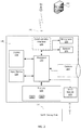
- Fig. 2 depicts source device 100 according to non-limiting implementations, comprising: a processor 220 connected to a camera 221, a memory 222, a display 224, an input device 226, a microphone 230, a speaker 232, optional communication interface 228 and Wi-Fi module 233, which is configured to operate in accordance with the MiracastTM standard for streaming audio and video to the sink device 110.
- source device 100 is capable of communicating via optional communication interface 228 with a remote central database 240, either wirelessly (as shown) or via a wired connection such as the Internet (not shown).
- Source device 100 can be any type of mobile electronic device that can be used to stream audio and video over a Wi-Fi link, including but not limited to, any combination of digital cameras, personal computers, laptop computers, mobile computing devices, portable computing devices, tablet computing devices, laptop computing devices, desktop phones, telephones, PDAs (personal digital assistants), cellphones, smartphones, e-readers, gaming devices, internet-configured appliances and the like.
- Fig. 2 depicts a schematic diagram of source device 100 according to non-limiting implementations. It should be emphasized that the structure of source device 100 in Fig. 2 is purely an example of a device having functionality to estimate input lag, as described in further detail below, but may also be used for wireless voice (e.g. telephony) and wireless data communications (e.g. email, web browsing, text, and the like), as well as other suitable specialized functions, including but not limited to one or more of camera functionality, telephony, computing, appliance, and/or entertainment related functions.
- wireless voice e.g. telephony
- wireless data communications e.g. email, web browsing, text, and the like
- suitable specialized functions including but not limited to one or more of camera functionality, telephony, computing, appliance, and/or entertainment related functions.
- Source device 100 comprises at least one input device 226 generally configured to receive input data, and can comprise any suitable combination of input devices, including but not limited to a keyboard, a keypad, a pointing device, a mouse, a track wheel, a trackball, a touchpad, a touch screen and the like. Other suitable input devices are within the scope of present implementations.
- processor 220 which can be implemented as a plurality of processors, including but not limited to one or more central processors (CPUs)).
- Processor 220 is configured to communicate with memory 222 comprising a non-volatile storage unit (e.g. Erasable Electronic Programmable Read Only Memory (“EEPROM”), Flash Memory) and a volatile storage unit (e.g. random access memory (“RAM”).
- EEPROM Erasable Electronic Programmable Read Only Memory
- RAM random access memory
- Programming instructions that implement the functionality of device 201 as described herein are typically maintained, persistently, in memory 222 and used by processor 220, which makes appropriate utilization of volatile storage during the execution of such programming instructions.
- memory 222 is an example of computer readable media that can store programming instructions executable on processor 220.
- memory 222 is also an example of a memory unit and/or memory module.
- memory 222 stores at least one application 250 that, when processed by processor 220, enables processor 220 to estimate input lag between source device 100 and sink device 110.
- memory 222 also stores at least one application 260 that, when processed by processor 220, encodes the audio/video payload according to the MiracastTM specification.
- Processor 220 can also be configured to communicate with display 224, microphone 230 and speaker 232.
- Display 224 comprises any suitable one of or combination of CRT (cathode ray tube) and/or flat panel displays (e.g. LCD (liquid crystal display), plasma, OLED (organic light emitting diode), capacitive or resistive touch screens, and the like).
- LCD liquid crystal display
- OLED organic light emitting diode
- Processor 220 can also be configured to communicate with display 224, microphone 230 and speaker 232.
- Display 224 comprises any suitable one of or combination of CRT (cathode ray tube) and/or flat panel displays (e.g. LCD (liquid crystal display), plasma, OLED (organic light emitting diode), capacitive or resistive touch screens, and the like).
- LCD liquid crystal display
- OLED organic light emitting diode
- Processor 220 can also be configured to communicate with display 224, microphone 230 and speaker 232.
- Display 224 comprises any suitable one of or
- processor 220 also connects to communication interface 228, which is implemented as one or more radios and/or connectors and/or network adaptors, configured to wirelessly communicate with central database 240 via one or more communication networks.
- communication interface 228 can be configured to correspond with the network architecture that is used to implement one or more communication links to the one or more communication networks, including but not limited to any suitable combination of USB (universal serial bus) cables, serial cables, wireless links, cell-phone links, cellular network links (including but not limited to 2G, 2.5G, 3G, 4G+, UMTS (Universal Mobile Telecommunications System), CDMA (Code division multiple access), WCDMA (Wideband CDMA), FDD (frequency division duplexing), TDD (time division duplexing), TDD-LTE (TDD-Long Term Evolution), TD-SCDMA (Time Division Synchronous Code Division Multiple Access) and the like, wireless data, Bluetooth links, NFC (near field communication) links, WiFi
- source device 100 further comprises one or more power sources, including but not limited to a battery and/or a connection to an external power source, including, but not limited to, a main power supply.
- power sources including but not limited to a battery and/or a connection to an external power source, including, but not limited to, a main power supply.
- source device 100 In any event, it should be understood that in general a wide variety of configurations for source device 100 are contemplated.
- memory 222 stores an input lag estimation application 250 which, when processed by processor 220, enables source device 100 to estimate the input lag between source device 100 and sink device 110.
- the input lag is estimated based on information relating to the manufacturer and model of the source device 100.
- the input lag is estimated based on a measurement of time delay between perceptible outputs at the source device 100 and sink device 110.
- application 250 starts at 300 and, at 310, the manufacturer and model of sink device 110 are identified.
- the source device 100 reads the display_edid message generated by sink device 110 for identifying manufacturer and model of sink device 110.
- the manufacturer and model of sink device 110 are entered into source device 100 via input device 226.
- the input lag information is pre-loaded as a table into memory 222 of source device 100, in which case the display_edid message is used at 330 as an index for locating the associated input lag. If the source device has not been pre-loaded with input lag data (i.e.
- the display_edid message is transmitted via communication interface 228, at 335, to central database 240, which contains the input lag information.
- the display_edid message is used within database 240 as an index for locating the associated input lag, which is then retrieved by source device 100 from database 240 at 340, using communication interface 228.
- the encoding of the audio/video payload, by application 260 is optimized using the input lag estimated by application 250 in order to adjust transmission parameters, as discussed above.
- input lag may be estimated using calibration techniques, as set forth in Fig. 4 , where the application 250 starts at 400 and then, at 410, generates a signal at source device 100; followed at 420 by detection of the resulting signal reproduced at sink device 110; measurement of a time delay, at 430, as an estimated input lag between the signals at the source device 100 and sink device 110; and, at 440, optimizing encoding of the audio/video payload by application 260 using the input lag estimated by application 250 in order to adjust transmission parameters as discussed above.
- the signal is a simple image.
- a simple image may be generated at 410 via display 224.
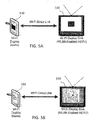
- the image may, for example, be a black square on white background, as shown in Fig. 5A , or other image having minimal compression latency and transmission bandwidth (e.g. a QR code or a series of color bands).
- a user activates input device 226 and the time delay (d1) between generation of the image and activation of the input device is measured.
- the procedure of measuring the delay between generating the image and detecting the input may be repeated multiple times and d1 may be averaged to reduce the impact of variations in user reaction time.
- the image is streamed to the sink device 110 in the usual manner and, at 420, in response to generation of the image at the sink device, the user activates input device 226 and the time delay (d2) between generation of the image at sink device 110 and activation of the input device is measured.
- the delay d2 includes the time it takes application 260 to encode the image, the time it takes to transmit the image from source device 100 to sink device 110, the input lag, , and the user response delay.
- the user response delay may be removed by subtracting d1 from d2, such that the remainder (d2 - d1- encoding, transmission and capture processing times) represents an accurate estimate of the input lag at the sink device 110.
- the signal is a discrete sound.
- a simple 'ping' sound may be generated at 410 via speaker 232.
- the audio is streamed to the sink device 110 in the usual manner and, at 420, in response to reproduction of the sound at the sink device the sound is detected by microphone 230 at the source device 100.
- the time delay (d) between generation of the sound at sink device 110 and detection at the source device 100 is measured at 430.
- the delay d includes the time it takes application 260 to encode the audio, the time it takes to transmit the audio from source device 100 to sink device 110, the input lag, the processing delay of sound detection (capture) at the input device 226, and the time for the audio to be transmitted from sink device 110 to source device 100 for detection by microphone 230.
- the time for the audio to be transmitted from sink device 110 to source device 100 may be assumed to be negligible and the encoding and transmission times are calculable as is the processing delay of sound detection (capture), and may be subtracted from d, such that the remainder represents an accurate estimate of the input lag at the sink device 110.
- the signal is a graphical representation of a timer, as shown in Fig. 5B .
- the video image of the timer is generated by application 250 on the display 224, and streamed to the sink device 110 in the usual manner.
- camera 221 captures the image at source device 100 and the input lag between the time appearing at the sink device 110 and the time appearing on the display 224 is measured at 430.
- the camera 221 may be pointed at the sink device 110 and the input device 226 activated to trigger the source device 100 to begin synchronization with the sink device 110.
- the source device 100 then transmits at least one simple image that require minimal encoding and compression, and source device 100 then measures d1 (the time of the transmission of the image) and d2 (the time when the image appearing on the screen of the sink device 110 is detected using the camera 221).
- d1 the time of the transmission of the image
- d2 the time when the image appearing on the screen of the sink device 110 is detected using the camera 221.
- the manufacturer of the source device 100 can also subtract the further delay that is measured between the time of display and the time of capture on the camera 221.
- source device 100 can be implemented using pre-programmed hardware or firmware elements (e.g., application specific integrated circuits (ASICs), electrically erasable programmable read-only memories (EEPROMs), etc.), or other related components.
- ASICs application specific integrated circuits
- EEPROMs electrically erasable programmable read-only memories
- the functionality of source device 100 can be achieved using a computing apparatus that has access to a code memory (not shown) which stores computer-readable program code for operation of the computing apparatus.
- the computer-readable program code could be stored on a computer readable storage medium which is fixed, tangible and readable directly by these components, (e.g., removable diskette, CD-ROM, ROM, fixed disk, USB drive).
- the computer-readable program can be stored as a computer program product comprising a computer usable medium.
- a persistent storage device can comprise the computer readable program code.
- the computer-readable program code and/or computer usable medium can comprise a non-transitory computer-readable program code and/or non-transitory computer usable medium.
- the computer-readable program code could be stored remotely but transmittable to these components via a modem or other interface device connected to a network (including, without limitation, the Internet) over a transmission medium.
- the transmission medium can be either a non-mobile medium (e.g., optical and/or digital and/or analog communications lines) or a mobile medium (e.g., microwave, infrared, free-space optical or other transmission schemes) or a combination thereof.
Landscapes
- Engineering & Computer Science (AREA)
- Multimedia (AREA)
- Computer Networks & Wireless Communication (AREA)
- Signal Processing (AREA)
- Two-Way Televisions, Distribution Of Moving Picture Or The Like (AREA)
Claims (6)
- Mobile tragbare Vorrichtung (100), umfassend:einen Prozessor (220) und ein WLAN-Modul (232) zum Kommunizieren mit einer Senkenvorrichtung (110), um Audio-/Videodaten aus einer Digitalvideobildschirm-Echtzeiterfassung darauf zu streamen;wobei die Senkenvorrichtung (110) eine Empfangsvorrichtung ist, die eine Anzeige zum Darstellen von Inhalt an einen Benutzer aufweist,der Prozessor (220) konfiguriert ist, um:den Hersteller und das Modell der Senkenvorrichtung (110) zu identifizieren (310),Eingabeverzögerungsdaten für die Senkenvorrichtung (110) aus einer Datenbank abzurufen (330, 340), die anhand des Herstellers und des Modells der Senkenvorrichtung (110) indiziert wird, unddas Verschlüsseln der Audio-/Videodaten durch Anpassen von Übertragungsparametern basierend auf den Eingabeverzögerungsdaten zu optimieren (350),wobei die Eingabeverzögerung der Senkenvorrichtung (110) als Differenz zwischen dem Zeitpunkt, an dem ein Signal in die Senkenvorrichtung (110) eingegeben wird, und dem Zeitpunkt, an dem es durch die Anzeige der Senkenvorrichtung (110) gezeigt wird, definiert ist.
- Mobile tragbare Vorrichtung nach Anspruch 1, wobei der Prozessor (220) konfiguriert ist, um den Hersteller und das Modell der Senkenvorrichtung (110) durch Lesen erweiterter Anzeige-Identifikationsdaten von der Senkenvorrichtung (110) zu identifizieren (310); und/oder die mobile tragbare Vorrichtung (100) ferner eine Eingabevorrichtung (226) beinhaltet und der Prozessor (220) ferner konfiguriert ist, um den Hersteller und das Modell der Senkenvorrichtung (110) durch Empfangen einer Dateneingabe davon über die Eingabevorrichtung (226) zu identifizieren (310).
- Mobile tragbare Vorrichtung nach einem der vorhergehenden Ansprüche, ferner beinhaltend einen Speicher (222) zum Speichern der Datenbank.
- Mobile tragbare Vorrichtung nach Anspruch 2, ferner beinhaltend eine Kommunikationsschnittstelle (228), wobei die Datenbank eine entfernte zentrale Datenbank (240) ist und der Prozessor (220) ferner konfiguriert ist, um die erweiterten Anzeige-Identifikationsdaten an die zentrale Datenbank (240) als Index zu senden und die Eingabeverzögerungsdaten für die Senkenvorrichtung (110) über die Kommunikationsschnittstelle (228) abzurufen.
- Verfahren zum Senden von Audio-/Videodaten von einer Digitalvideobildschirm-Echtzeiterfassung von einer mobilen tragbaren Vorrichtung (100) an eine Senkenvorrichtung (110), umfassend:i) Identifizieren (310) des Herstellers und des Modells der Senkenvorrichtung (110);ii) Abrufen (330, 340) von Eingabeverzögerungsdaten für die Senkenvorrichtung (110) aus einer Datenbank, die anhand des Herstellers und des Modells der Senkenvorrichtung (110) indiziert wird; undiii) Optimieren (350) des Verschlüsselns der Audio-/Videodaten durch Anpassen von Übertragungsparametern basierend auf den Eingabeverzögerungsdaten,wobei die Senkenvorrichtung (110) eine Empfangsvorrichtung ist, die eine Anzeige zum Darstellen von Inhalt an einen Benutzer aufweist, und
wobei die Eingabeverzögerung der Senkenvorrichtung (110) als Differenz zwischen dem Zeitpunkt, an dem ein Signal in die Senkenvorrichtung (110) eingegeben wird, und dem Zeitpunkt, an dem es durch die Anzeige gezeigt wird, definiert ist. - Verfahren nach Anspruch 5, ferner beinhaltend das Senden (335) der erweiterten Anzeige-Identifikationsdaten an eine zentrale Datenbank (240) als Index und Abrufen (340) der Eingabeverzögerungsdaten für die Senkenvorrichtung (110) von der zentralen Datenbank (240).
Priority Applications (1)
| Application Number | Priority Date | Filing Date | Title |
|---|---|---|---|
| EP13166511.9A EP2800331B1 (de) | 2013-05-03 | 2013-05-03 | Eingabe-lag-schätzung für wi-fi-anzeigesenken |
Applications Claiming Priority (1)
| Application Number | Priority Date | Filing Date | Title |
|---|---|---|---|
| EP13166511.9A EP2800331B1 (de) | 2013-05-03 | 2013-05-03 | Eingabe-lag-schätzung für wi-fi-anzeigesenken |
Publications (2)
| Publication Number | Publication Date |
|---|---|
| EP2800331A1 EP2800331A1 (de) | 2014-11-05 |
| EP2800331B1 true EP2800331B1 (de) | 2019-08-14 |
Family
ID=48326145
Family Applications (1)
| Application Number | Title | Priority Date | Filing Date |
|---|---|---|---|
| EP13166511.9A Active EP2800331B1 (de) | 2013-05-03 | 2013-05-03 | Eingabe-lag-schätzung für wi-fi-anzeigesenken |
Country Status (1)
| Country | Link |
|---|---|
| EP (1) | EP2800331B1 (de) |
Families Citing this family (1)
| Publication number | Priority date | Publication date | Assignee | Title |
|---|---|---|---|---|
| CN106210708B (zh) | 2015-04-30 | 2019-02-01 | 杭州海康威视数字技术股份有限公司 | 一种图像延迟的检测方法和系统 |
Citations (3)
| Publication number | Priority date | Publication date | Assignee | Title |
|---|---|---|---|---|
| US20030233461A1 (en) * | 2002-06-12 | 2003-12-18 | Telefonaktiebolaget Lm Ericsson (Publ) | Method, system and apparatus for handling terminal capabilities |
| US20100161804A1 (en) * | 2008-12-18 | 2010-06-24 | Electronics And Telecommunications Research Institute | System and method for providing device file using device identifier |
| WO2013056031A1 (en) * | 2011-10-14 | 2013-04-18 | Qualcomm Incorporated | Feedback channel for wireless display devices |
Family Cites Families (2)
| Publication number | Priority date | Publication date | Assignee | Title |
|---|---|---|---|---|
| KR100550567B1 (ko) * | 2004-03-22 | 2006-02-10 | 엘지전자 주식회사 | 무선 네트워크망을 통해 통신하는 서버 시스템 및 그동작방법 |
| US8599235B2 (en) * | 2009-07-27 | 2013-12-03 | Cisco Technology, Inc. | Automatic display latency measurement system for video conferencing |
-
2013
- 2013-05-03 EP EP13166511.9A patent/EP2800331B1/de active Active
Patent Citations (3)
| Publication number | Priority date | Publication date | Assignee | Title |
|---|---|---|---|---|
| US20030233461A1 (en) * | 2002-06-12 | 2003-12-18 | Telefonaktiebolaget Lm Ericsson (Publ) | Method, system and apparatus for handling terminal capabilities |
| US20100161804A1 (en) * | 2008-12-18 | 2010-06-24 | Electronics And Telecommunications Research Institute | System and method for providing device file using device identifier |
| WO2013056031A1 (en) * | 2011-10-14 | 2013-04-18 | Qualcomm Incorporated | Feedback channel for wireless display devices |
Non-Patent Citations (6)
| Title |
|---|
| ADEEL SOOMRO, FOUR WUDE: "What is Input Lag: The Breakdown", INTERNET ARCHIVE WAYBACK MACHINE, 24 February 2013 (2013-02-24), Internet Archive Wayback Machine, Retrieved from the Internet <URL:https://web.archive.org/web/20130224022856/https://displaylag.com/what-is-input-lag-the-breakdown/> [retrieved on 20170718] * |
| ADEEL SOOMRO: "What is Input Lag: The Breakdown | DisplayLag", DISPLAY LAG, 3 February 2013 (2013-02-03), XP055271243, Retrieved from the Internet <URL:http://www.displaylag.com/what-is-input-lag-the-breakdown/> [retrieved on 20160509] * |
| DALE NORTH: "This HDTV Monitor Lag database could be handy - Destructoid", 19 February 2013 (2013-02-19), XP055391882, Retrieved from the Internet <URL:https://web.archive.org/web/20130219010924/http:/www.destructoid.com/this-hdtv-monitor-lag-database-could-be-handy-245068.phtml> [retrieved on 20170718] * |
| DALE NORTH: "This HDTV Monitor Lag Database could be handy", 15 February 2013 (2013-02-15), pages 1, XP055271264, Retrieved from the Internet <URL:http://www.destructoid.com/this-hdtv-monitor-lag-database-could-be-handy-245068.phtml> [retrieved on 20160509] * |
| DISPLAY LAG: "Input Lag Database for the Best Gaming Monitors & HDTVs | Display Lag", 24 February 2013 (2013-02-24), INTERNET ARCHIVE WAYBACK MACHINE, pages 1 - 7, XP055391875, Retrieved from the Internet <URL:https://web.archive.org/web/20130224022754/http://www.displaylag.com:80/display-database/> [retrieved on 20170718] * |
| WI-FI ALLIANCE: "Wi-Fi Alliance Technical Committee Wi-Fi Display Technical Task Group Wi-Fi Display Technical Specification", 1 January 2012 (2012-01-01), XP055320680, Retrieved from the Internet <URL:http://www.wi-fi.org/> [retrieved on 20161117] * |
Also Published As
| Publication number | Publication date |
|---|---|
| EP2800331A1 (de) | 2014-11-05 |
Similar Documents
| Publication | Publication Date | Title |
|---|---|---|
| US9497506B2 (en) | Input lag estimation for Wi-Fi display sinks | |
| US11477316B2 (en) | Information processing system, wireless terminal, and information processing method | |
| US9913301B2 (en) | Content sharing method and device | |
| US8300079B2 (en) | Apparatus and method for transferring video | |
| EP3028498B1 (de) | Drahtlose übertragung von echtzeit-medien | |
| US10098080B2 (en) | Device, method and computer readable medium | |
| RU2656230C2 (ru) | Устройство обработки информации и способ обработки информации | |
| US10805613B2 (en) | Systems and methods for optimization and testing of wireless devices | |
| US10268436B2 (en) | Communication apparatus, control method therefor, and non-transitory computer-readable storage medium | |
| EP2986020B1 (de) | Verfahren und vorrichtung zur einstellung der videoqualität basierend auf der netzwerkumgebung | |
| US10285035B2 (en) | Communication apparatus and control method therefor | |
| US10237318B2 (en) | Electronic device and method for encoding image data thereof | |
| US20130058593A1 (en) | System and method for calibrating display overscan using a mobile device | |
| KR20130097336A (ko) | 전자 장치 사이의 스트림 전송 방법 및 그 방법을 처리하는 전자 장치 | |
| CN104657099A (zh) | 屏幕投射方法、装置及系统 | |
| US9344678B2 (en) | Information processing apparatus, information processing method and computer-readable storage medium | |
| CN107197320B (zh) | 视频直播方法、装置和系统 | |
| US11435973B2 (en) | Communication apparatus, communication method, and storage medium | |
| CN111245854B (zh) | 一种媒体传输方法、媒体控制方法及装置 | |
| US10582376B2 (en) | Information processing apparatus, information processing method, and source apparatus | |
| JP6139297B2 (ja) | 電子機器、表示データの送信方法およびプログラム | |
| US9332308B2 (en) | Image communication apparatus and control method therefor | |
| EP2800331B1 (de) | Eingabe-lag-schätzung für wi-fi-anzeigesenken | |
| JP6455121B2 (ja) | 情報処理装置、情報処理方法およびプログラム | |
| US20130097648A1 (en) | Internet-enabled smart television |
Legal Events
| Date | Code | Title | Description |
|---|---|---|---|
| PUAI | Public reference made under article 153(3) epc to a published international application that has entered the european phase |
Free format text: ORIGINAL CODE: 0009012 |
|
| 17P | Request for examination filed |
Effective date: 20130503 |
|
| AK | Designated contracting states |
Kind code of ref document: A1 Designated state(s): AL AT BE BG CH CY CZ DE DK EE ES FI FR GB GR HR HU IE IS IT LI LT LU LV MC MK MT NL NO PL PT RO RS SE SI SK SM TR |
|
| AX | Request for extension of the european patent |
Extension state: BA ME |
|
| 17Q | First examination report despatched |
Effective date: 20160517 |
|
| STAA | Information on the status of an ep patent application or granted ep patent |
Free format text: STATUS: EXAMINATION IS IN PROGRESS |
|
| GRAP | Despatch of communication of intention to grant a patent |
Free format text: ORIGINAL CODE: EPIDOSNIGR1 |
|
| STAA | Information on the status of an ep patent application or granted ep patent |
Free format text: STATUS: GRANT OF PATENT IS INTENDED |
|
| INTG | Intention to grant announced |
Effective date: 20190301 |
|
| GRAS | Grant fee paid |
Free format text: ORIGINAL CODE: EPIDOSNIGR3 |
|
| GRAA | (expected) grant |
Free format text: ORIGINAL CODE: 0009210 |
|
| STAA | Information on the status of an ep patent application or granted ep patent |
Free format text: STATUS: THE PATENT HAS BEEN GRANTED |
|
| AK | Designated contracting states |
Kind code of ref document: B1 Designated state(s): AL AT BE BG CH CY CZ DE DK EE ES FI FR GB GR HR HU IE IS IT LI LT LU LV MC MK MT NL NO PL PT RO RS SE SI SK SM TR |
|
| REG | Reference to a national code |
Ref country code: GB Ref legal event code: FG4D |
|
| REG | Reference to a national code |
Ref country code: CH Ref legal event code: EP Ref country code: AT Ref legal event code: REF Ref document number: 1168366 Country of ref document: AT Kind code of ref document: T Effective date: 20190815 |
|
| REG | Reference to a national code |
Ref country code: IE Ref legal event code: FG4D |
|
| REG | Reference to a national code |
Ref country code: DE Ref legal event code: R096 Ref document number: 602013059054 Country of ref document: DE |
|
| REG | Reference to a national code |
Ref country code: NL Ref legal event code: MP Effective date: 20190814 |
|
| REG | Reference to a national code |
Ref country code: LT Ref legal event code: MG4D |
|
| PG25 | Lapsed in a contracting state [announced via postgrant information from national office to epo] |
Ref country code: FI Free format text: LAPSE BECAUSE OF FAILURE TO SUBMIT A TRANSLATION OF THE DESCRIPTION OR TO PAY THE FEE WITHIN THE PRESCRIBED TIME-LIMIT Effective date: 20190814 Ref country code: NO Free format text: LAPSE BECAUSE OF FAILURE TO SUBMIT A TRANSLATION OF THE DESCRIPTION OR TO PAY THE FEE WITHIN THE PRESCRIBED TIME-LIMIT Effective date: 20191114 Ref country code: HR Free format text: LAPSE BECAUSE OF FAILURE TO SUBMIT A TRANSLATION OF THE DESCRIPTION OR TO PAY THE FEE WITHIN THE PRESCRIBED TIME-LIMIT Effective date: 20190814 Ref country code: LT Free format text: LAPSE BECAUSE OF FAILURE TO SUBMIT A TRANSLATION OF THE DESCRIPTION OR TO PAY THE FEE WITHIN THE PRESCRIBED TIME-LIMIT Effective date: 20190814 Ref country code: BG Free format text: LAPSE BECAUSE OF FAILURE TO SUBMIT A TRANSLATION OF THE DESCRIPTION OR TO PAY THE FEE WITHIN THE PRESCRIBED TIME-LIMIT Effective date: 20191114 Ref country code: SE Free format text: LAPSE BECAUSE OF FAILURE TO SUBMIT A TRANSLATION OF THE DESCRIPTION OR TO PAY THE FEE WITHIN THE PRESCRIBED TIME-LIMIT Effective date: 20190814 Ref country code: NL Free format text: LAPSE BECAUSE OF FAILURE TO SUBMIT A TRANSLATION OF THE DESCRIPTION OR TO PAY THE FEE WITHIN THE PRESCRIBED TIME-LIMIT Effective date: 20190814 Ref country code: PT Free format text: LAPSE BECAUSE OF FAILURE TO SUBMIT A TRANSLATION OF THE DESCRIPTION OR TO PAY THE FEE WITHIN THE PRESCRIBED TIME-LIMIT Effective date: 20191216 |
|
| REG | Reference to a national code |
Ref country code: AT Ref legal event code: MK05 Ref document number: 1168366 Country of ref document: AT Kind code of ref document: T Effective date: 20190814 |
|
| PG25 | Lapsed in a contracting state [announced via postgrant information from national office to epo] |
Ref country code: AL Free format text: LAPSE BECAUSE OF FAILURE TO SUBMIT A TRANSLATION OF THE DESCRIPTION OR TO PAY THE FEE WITHIN THE PRESCRIBED TIME-LIMIT Effective date: 20190814 Ref country code: GR Free format text: LAPSE BECAUSE OF FAILURE TO SUBMIT A TRANSLATION OF THE DESCRIPTION OR TO PAY THE FEE WITHIN THE PRESCRIBED TIME-LIMIT Effective date: 20191115 Ref country code: IS Free format text: LAPSE BECAUSE OF FAILURE TO SUBMIT A TRANSLATION OF THE DESCRIPTION OR TO PAY THE FEE WITHIN THE PRESCRIBED TIME-LIMIT Effective date: 20191214 Ref country code: RS Free format text: LAPSE BECAUSE OF FAILURE TO SUBMIT A TRANSLATION OF THE DESCRIPTION OR TO PAY THE FEE WITHIN THE PRESCRIBED TIME-LIMIT Effective date: 20190814 Ref country code: LV Free format text: LAPSE BECAUSE OF FAILURE TO SUBMIT A TRANSLATION OF THE DESCRIPTION OR TO PAY THE FEE WITHIN THE PRESCRIBED TIME-LIMIT Effective date: 20190814 Ref country code: ES Free format text: LAPSE BECAUSE OF FAILURE TO SUBMIT A TRANSLATION OF THE DESCRIPTION OR TO PAY THE FEE WITHIN THE PRESCRIBED TIME-LIMIT Effective date: 20190814 |
|
| PG25 | Lapsed in a contracting state [announced via postgrant information from national office to epo] |
Ref country code: TR Free format text: LAPSE BECAUSE OF FAILURE TO SUBMIT A TRANSLATION OF THE DESCRIPTION OR TO PAY THE FEE WITHIN THE PRESCRIBED TIME-LIMIT Effective date: 20190814 |
|
| PG25 | Lapsed in a contracting state [announced via postgrant information from national office to epo] |
Ref country code: IT Free format text: LAPSE BECAUSE OF FAILURE TO SUBMIT A TRANSLATION OF THE DESCRIPTION OR TO PAY THE FEE WITHIN THE PRESCRIBED TIME-LIMIT Effective date: 20190814 Ref country code: PL Free format text: LAPSE BECAUSE OF FAILURE TO SUBMIT A TRANSLATION OF THE DESCRIPTION OR TO PAY THE FEE WITHIN THE PRESCRIBED TIME-LIMIT Effective date: 20190814 Ref country code: AT Free format text: LAPSE BECAUSE OF FAILURE TO SUBMIT A TRANSLATION OF THE DESCRIPTION OR TO PAY THE FEE WITHIN THE PRESCRIBED TIME-LIMIT Effective date: 20190814 Ref country code: DK Free format text: LAPSE BECAUSE OF FAILURE TO SUBMIT A TRANSLATION OF THE DESCRIPTION OR TO PAY THE FEE WITHIN THE PRESCRIBED TIME-LIMIT Effective date: 20190814 Ref country code: EE Free format text: LAPSE BECAUSE OF FAILURE TO SUBMIT A TRANSLATION OF THE DESCRIPTION OR TO PAY THE FEE WITHIN THE PRESCRIBED TIME-LIMIT Effective date: 20190814 Ref country code: RO Free format text: LAPSE BECAUSE OF FAILURE TO SUBMIT A TRANSLATION OF THE DESCRIPTION OR TO PAY THE FEE WITHIN THE PRESCRIBED TIME-LIMIT Effective date: 20190814 |
|
| PG25 | Lapsed in a contracting state [announced via postgrant information from national office to epo] |
Ref country code: CZ Free format text: LAPSE BECAUSE OF FAILURE TO SUBMIT A TRANSLATION OF THE DESCRIPTION OR TO PAY THE FEE WITHIN THE PRESCRIBED TIME-LIMIT Effective date: 20190814 Ref country code: SM Free format text: LAPSE BECAUSE OF FAILURE TO SUBMIT A TRANSLATION OF THE DESCRIPTION OR TO PAY THE FEE WITHIN THE PRESCRIBED TIME-LIMIT Effective date: 20190814 Ref country code: SK Free format text: LAPSE BECAUSE OF FAILURE TO SUBMIT A TRANSLATION OF THE DESCRIPTION OR TO PAY THE FEE WITHIN THE PRESCRIBED TIME-LIMIT Effective date: 20190814 Ref country code: IS Free format text: LAPSE BECAUSE OF FAILURE TO SUBMIT A TRANSLATION OF THE DESCRIPTION OR TO PAY THE FEE WITHIN THE PRESCRIBED TIME-LIMIT Effective date: 20200224 |
|
| REG | Reference to a national code |
Ref country code: DE Ref legal event code: R097 Ref document number: 602013059054 Country of ref document: DE |
|
| PLBE | No opposition filed within time limit |
Free format text: ORIGINAL CODE: 0009261 |
|
| STAA | Information on the status of an ep patent application or granted ep patent |
Free format text: STATUS: NO OPPOSITION FILED WITHIN TIME LIMIT |
|
| PG2D | Information on lapse in contracting state deleted |
Ref country code: IS |
|
| 26N | No opposition filed |
Effective date: 20200603 |
|
| PG25 | Lapsed in a contracting state [announced via postgrant information from national office to epo] |
Ref country code: SI Free format text: LAPSE BECAUSE OF FAILURE TO SUBMIT A TRANSLATION OF THE DESCRIPTION OR TO PAY THE FEE WITHIN THE PRESCRIBED TIME-LIMIT Effective date: 20190814 |
|
| PG25 | Lapsed in a contracting state [announced via postgrant information from national office to epo] |
Ref country code: MC Free format text: LAPSE BECAUSE OF FAILURE TO SUBMIT A TRANSLATION OF THE DESCRIPTION OR TO PAY THE FEE WITHIN THE PRESCRIBED TIME-LIMIT Effective date: 20190814 Ref country code: LI Free format text: LAPSE BECAUSE OF NON-PAYMENT OF DUE FEES Effective date: 20200531 Ref country code: CH Free format text: LAPSE BECAUSE OF NON-PAYMENT OF DUE FEES Effective date: 20200531 |
|
| REG | Reference to a national code |
Ref country code: BE Ref legal event code: MM Effective date: 20200531 |
|
| PG25 | Lapsed in a contracting state [announced via postgrant information from national office to epo] |
Ref country code: LU Free format text: LAPSE BECAUSE OF NON-PAYMENT OF DUE FEES Effective date: 20200503 |
|
| PG25 | Lapsed in a contracting state [announced via postgrant information from national office to epo] |
Ref country code: IE Free format text: LAPSE BECAUSE OF NON-PAYMENT OF DUE FEES Effective date: 20200503 |
|
| PG25 | Lapsed in a contracting state [announced via postgrant information from national office to epo] |
Ref country code: BE Free format text: LAPSE BECAUSE OF NON-PAYMENT OF DUE FEES Effective date: 20200531 |
|
| REG | Reference to a national code |
Ref country code: DE Ref legal event code: R079 Ref document number: 602013059054 Country of ref document: DE Free format text: PREVIOUS MAIN CLASS: H04L0029060000 Ipc: H04L0065000000 |
|
| PG25 | Lapsed in a contracting state [announced via postgrant information from national office to epo] |
Ref country code: MT Free format text: LAPSE BECAUSE OF FAILURE TO SUBMIT A TRANSLATION OF THE DESCRIPTION OR TO PAY THE FEE WITHIN THE PRESCRIBED TIME-LIMIT Effective date: 20190814 Ref country code: CY Free format text: LAPSE BECAUSE OF FAILURE TO SUBMIT A TRANSLATION OF THE DESCRIPTION OR TO PAY THE FEE WITHIN THE PRESCRIBED TIME-LIMIT Effective date: 20190814 |
|
| PG25 | Lapsed in a contracting state [announced via postgrant information from national office to epo] |
Ref country code: MK Free format text: LAPSE BECAUSE OF FAILURE TO SUBMIT A TRANSLATION OF THE DESCRIPTION OR TO PAY THE FEE WITHIN THE PRESCRIBED TIME-LIMIT Effective date: 20190814 |
|
| REG | Reference to a national code |
Ref country code: DE Ref legal event code: R082 Ref document number: 602013059054 Country of ref document: DE Ref country code: DE Ref legal event code: R081 Ref document number: 602013059054 Country of ref document: DE Owner name: MALIKIE INNOVATIONS LTD., IE Free format text: FORMER OWNER: BLACKBERRY LTD., WATERLOO, ONTARIO, CA |
|
| REG | Reference to a national code |
Ref country code: GB Ref legal event code: 732E Free format text: REGISTERED BETWEEN 20240620 AND 20240627 |
|
| PGFP | Annual fee paid to national office [announced via postgrant information from national office to epo] |
Ref country code: DE Payment date: 20250528 Year of fee payment: 13 |
|
| PGFP | Annual fee paid to national office [announced via postgrant information from national office to epo] |
Ref country code: FR Payment date: 20250526 Year of fee payment: 13 |
|
| PGFP | Annual fee paid to national office [announced via postgrant information from national office to epo] |
Ref country code: GB Payment date: 20260319 Year of fee payment: 14 |