EP2800233A1 - Circuit arrangement with a resonance converter and method for operating a resonance converter - Google Patents
Circuit arrangement with a resonance converter and method for operating a resonance converter Download PDFInfo
- Publication number
- EP2800233A1 EP2800233A1 EP20140157472 EP14157472A EP2800233A1 EP 2800233 A1 EP2800233 A1 EP 2800233A1 EP 20140157472 EP20140157472 EP 20140157472 EP 14157472 A EP14157472 A EP 14157472A EP 2800233 A1 EP2800233 A1 EP 2800233A1
- Authority
- EP
- European Patent Office
- Prior art keywords
- controller
- resonant converter
- primary
- circuit arrangement
- idle detection
- Prior art date
- Legal status (The legal status is an assumption and is not a legal conclusion. Google has not performed a legal analysis and makes no representation as to the accuracy of the status listed.)
- Granted
Links
Images


Classifications
-
- H—ELECTRICITY
- H02—GENERATION; CONVERSION OR DISTRIBUTION OF ELECTRIC POWER
- H02J—CIRCUIT ARRANGEMENTS OR SYSTEMS FOR SUPPLYING OR DISTRIBUTING ELECTRIC POWER; SYSTEMS FOR STORING ELECTRIC ENERGY
- H02J7/00—Circuit arrangements for charging or depolarising batteries or for supplying loads from batteries
- H02J7/007—Regulation of charging or discharging current or voltage
- H02J7/00712—Regulation of charging or discharging current or voltage the cycle being controlled or terminated in response to electric parameters
-
- B—PERFORMING OPERATIONS; TRANSPORTING
- B60—VEHICLES IN GENERAL
- B60L—PROPULSION OF ELECTRICALLY-PROPELLED VEHICLES; SUPPLYING ELECTRIC POWER FOR AUXILIARY EQUIPMENT OF ELECTRICALLY-PROPELLED VEHICLES; ELECTRODYNAMIC BRAKE SYSTEMS FOR VEHICLES IN GENERAL; MAGNETIC SUSPENSION OR LEVITATION FOR VEHICLES; MONITORING OPERATING VARIABLES OF ELECTRICALLY-PROPELLED VEHICLES; ELECTRIC SAFETY DEVICES FOR ELECTRICALLY-PROPELLED VEHICLES
- B60L3/00—Electric devices on electrically-propelled vehicles for safety purposes; Monitoring operating variables, e.g. speed, deceleration or energy consumption
- B60L3/0023—Detecting, eliminating, remedying or compensating for drive train abnormalities, e.g. failures within the drive train
- B60L3/0069—Detecting, eliminating, remedying or compensating for drive train abnormalities, e.g. failures within the drive train relating to the isolation, e.g. ground fault or leak current
-
- B—PERFORMING OPERATIONS; TRANSPORTING
- B60—VEHICLES IN GENERAL
- B60L—PROPULSION OF ELECTRICALLY-PROPELLED VEHICLES; SUPPLYING ELECTRIC POWER FOR AUXILIARY EQUIPMENT OF ELECTRICALLY-PROPELLED VEHICLES; ELECTRODYNAMIC BRAKE SYSTEMS FOR VEHICLES IN GENERAL; MAGNETIC SUSPENSION OR LEVITATION FOR VEHICLES; MONITORING OPERATING VARIABLES OF ELECTRICALLY-PROPELLED VEHICLES; ELECTRIC SAFETY DEVICES FOR ELECTRICALLY-PROPELLED VEHICLES
- B60L3/00—Electric devices on electrically-propelled vehicles for safety purposes; Monitoring operating variables, e.g. speed, deceleration or energy consumption
- B60L3/04—Cutting off the power supply under fault conditions
-
- B—PERFORMING OPERATIONS; TRANSPORTING
- B60—VEHICLES IN GENERAL
- B60L—PROPULSION OF ELECTRICALLY-PROPELLED VEHICLES; SUPPLYING ELECTRIC POWER FOR AUXILIARY EQUIPMENT OF ELECTRICALLY-PROPELLED VEHICLES; ELECTRODYNAMIC BRAKE SYSTEMS FOR VEHICLES IN GENERAL; MAGNETIC SUSPENSION OR LEVITATION FOR VEHICLES; MONITORING OPERATING VARIABLES OF ELECTRICALLY-PROPELLED VEHICLES; ELECTRIC SAFETY DEVICES FOR ELECTRICALLY-PROPELLED VEHICLES
- B60L50/00—Electric propulsion with power supplied within the vehicle
- B60L50/50—Electric propulsion with power supplied within the vehicle using propulsion power supplied by batteries or fuel cells
- B60L50/52—Electric propulsion with power supplied within the vehicle using propulsion power supplied by batteries or fuel cells characterised by DC-motors
-
- B—PERFORMING OPERATIONS; TRANSPORTING
- B60—VEHICLES IN GENERAL
- B60L—PROPULSION OF ELECTRICALLY-PROPELLED VEHICLES; SUPPLYING ELECTRIC POWER FOR AUXILIARY EQUIPMENT OF ELECTRICALLY-PROPELLED VEHICLES; ELECTRODYNAMIC BRAKE SYSTEMS FOR VEHICLES IN GENERAL; MAGNETIC SUSPENSION OR LEVITATION FOR VEHICLES; MONITORING OPERATING VARIABLES OF ELECTRICALLY-PROPELLED VEHICLES; ELECTRIC SAFETY DEVICES FOR ELECTRICALLY-PROPELLED VEHICLES
- B60L53/00—Methods of charging batteries, specially adapted for electric vehicles; Charging stations or on-board charging equipment therefor; Exchange of energy storage elements in electric vehicles
- B60L53/10—Methods of charging batteries, specially adapted for electric vehicles; Charging stations or on-board charging equipment therefor; Exchange of energy storage elements in electric vehicles characterised by the energy transfer between the charging station and the vehicle
- B60L53/12—Inductive energy transfer
- B60L53/126—Methods for pairing a vehicle and a charging station, e.g. establishing a one-to-one relation between a wireless power transmitter and a wireless power receiver
-
- B—PERFORMING OPERATIONS; TRANSPORTING
- B60—VEHICLES IN GENERAL
- B60L—PROPULSION OF ELECTRICALLY-PROPELLED VEHICLES; SUPPLYING ELECTRIC POWER FOR AUXILIARY EQUIPMENT OF ELECTRICALLY-PROPELLED VEHICLES; ELECTRODYNAMIC BRAKE SYSTEMS FOR VEHICLES IN GENERAL; MAGNETIC SUSPENSION OR LEVITATION FOR VEHICLES; MONITORING OPERATING VARIABLES OF ELECTRICALLY-PROPELLED VEHICLES; ELECTRIC SAFETY DEVICES FOR ELECTRICALLY-PROPELLED VEHICLES
- B60L53/00—Methods of charging batteries, specially adapted for electric vehicles; Charging stations or on-board charging equipment therefor; Exchange of energy storage elements in electric vehicles
- B60L53/20—Methods of charging batteries, specially adapted for electric vehicles; Charging stations or on-board charging equipment therefor; Exchange of energy storage elements in electric vehicles characterised by converters located in the vehicle
- B60L53/22—Constructional details or arrangements of charging converters specially adapted for charging electric vehicles
-
- B—PERFORMING OPERATIONS; TRANSPORTING
- B60—VEHICLES IN GENERAL
- B60L—PROPULSION OF ELECTRICALLY-PROPELLED VEHICLES; SUPPLYING ELECTRIC POWER FOR AUXILIARY EQUIPMENT OF ELECTRICALLY-PROPELLED VEHICLES; ELECTRODYNAMIC BRAKE SYSTEMS FOR VEHICLES IN GENERAL; MAGNETIC SUSPENSION OR LEVITATION FOR VEHICLES; MONITORING OPERATING VARIABLES OF ELECTRICALLY-PROPELLED VEHICLES; ELECTRIC SAFETY DEVICES FOR ELECTRICALLY-PROPELLED VEHICLES
- B60L53/00—Methods of charging batteries, specially adapted for electric vehicles; Charging stations or on-board charging equipment therefor; Exchange of energy storage elements in electric vehicles
- B60L53/60—Monitoring or controlling charging stations
- B60L53/65—Monitoring or controlling charging stations involving identification of vehicles or their battery types
-
- B—PERFORMING OPERATIONS; TRANSPORTING
- B60—VEHICLES IN GENERAL
- B60L—PROPULSION OF ELECTRICALLY-PROPELLED VEHICLES; SUPPLYING ELECTRIC POWER FOR AUXILIARY EQUIPMENT OF ELECTRICALLY-PROPELLED VEHICLES; ELECTRODYNAMIC BRAKE SYSTEMS FOR VEHICLES IN GENERAL; MAGNETIC SUSPENSION OR LEVITATION FOR VEHICLES; MONITORING OPERATING VARIABLES OF ELECTRICALLY-PROPELLED VEHICLES; ELECTRIC SAFETY DEVICES FOR ELECTRICALLY-PROPELLED VEHICLES
- B60L58/00—Methods or circuit arrangements for monitoring or controlling batteries or fuel cells, specially adapted for electric vehicles
- B60L58/10—Methods or circuit arrangements for monitoring or controlling batteries or fuel cells, specially adapted for electric vehicles for monitoring or controlling batteries
- B60L58/12—Methods or circuit arrangements for monitoring or controlling batteries or fuel cells, specially adapted for electric vehicles for monitoring or controlling batteries responding to state of charge [SoC]
-
- H—ELECTRICITY
- H02—GENERATION; CONVERSION OR DISTRIBUTION OF ELECTRIC POWER
- H02J—CIRCUIT ARRANGEMENTS OR SYSTEMS FOR SUPPLYING OR DISTRIBUTING ELECTRIC POWER; SYSTEMS FOR STORING ELECTRIC ENERGY
- H02J50/00—Circuit arrangements or systems for wireless supply or distribution of electric power
- H02J50/10—Circuit arrangements or systems for wireless supply or distribution of electric power using inductive coupling
- H02J50/12—Circuit arrangements or systems for wireless supply or distribution of electric power using inductive coupling of the resonant type
-
- H—ELECTRICITY
- H02—GENERATION; CONVERSION OR DISTRIBUTION OF ELECTRIC POWER
- H02J—CIRCUIT ARRANGEMENTS OR SYSTEMS FOR SUPPLYING OR DISTRIBUTING ELECTRIC POWER; SYSTEMS FOR STORING ELECTRIC ENERGY
- H02J50/00—Circuit arrangements or systems for wireless supply or distribution of electric power
- H02J50/80—Circuit arrangements or systems for wireless supply or distribution of electric power involving the exchange of data, concerning supply or distribution of electric power, between transmitting devices and receiving devices
-
- H—ELECTRICITY
- H02—GENERATION; CONVERSION OR DISTRIBUTION OF ELECTRIC POWER
- H02J—CIRCUIT ARRANGEMENTS OR SYSTEMS FOR SUPPLYING OR DISTRIBUTING ELECTRIC POWER; SYSTEMS FOR STORING ELECTRIC ENERGY
- H02J7/00—Circuit arrangements for charging or depolarising batteries or for supplying loads from batteries
- H02J7/0029—Circuit arrangements for charging or depolarising batteries or for supplying loads from batteries with safety or protection devices or circuits
- H02J7/00304—Overcurrent protection
-
- H—ELECTRICITY
- H02—GENERATION; CONVERSION OR DISTRIBUTION OF ELECTRIC POWER
- H02M—APPARATUS FOR CONVERSION BETWEEN AC AND AC, BETWEEN AC AND DC, OR BETWEEN DC AND DC, AND FOR USE WITH MAINS OR SIMILAR POWER SUPPLY SYSTEMS; CONVERSION OF DC OR AC INPUT POWER INTO SURGE OUTPUT POWER; CONTROL OR REGULATION THEREOF
- H02M3/00—Conversion of dc power input into dc power output
- H02M3/22—Conversion of dc power input into dc power output with intermediate conversion into ac
- H02M3/24—Conversion of dc power input into dc power output with intermediate conversion into ac by static converters
- H02M3/28—Conversion of dc power input into dc power output with intermediate conversion into ac by static converters using discharge tubes with control electrode or semiconductor devices with control electrode to produce the intermediate ac
- H02M3/325—Conversion of dc power input into dc power output with intermediate conversion into ac by static converters using discharge tubes with control electrode or semiconductor devices with control electrode to produce the intermediate ac using devices of a triode or a transistor type requiring continuous application of a control signal
- H02M3/335—Conversion of dc power input into dc power output with intermediate conversion into ac by static converters using discharge tubes with control electrode or semiconductor devices with control electrode to produce the intermediate ac using devices of a triode or a transistor type requiring continuous application of a control signal using semiconductor devices only
- H02M3/33507—Conversion of dc power input into dc power output with intermediate conversion into ac by static converters using discharge tubes with control electrode or semiconductor devices with control electrode to produce the intermediate ac using devices of a triode or a transistor type requiring continuous application of a control signal using semiconductor devices only with automatic control of the output voltage or current, e.g. flyback converters
- H02M3/33515—Conversion of dc power input into dc power output with intermediate conversion into ac by static converters using discharge tubes with control electrode or semiconductor devices with control electrode to produce the intermediate ac using devices of a triode or a transistor type requiring continuous application of a control signal using semiconductor devices only with automatic control of the output voltage or current, e.g. flyback converters with digital control
-
- B—PERFORMING OPERATIONS; TRANSPORTING
- B60—VEHICLES IN GENERAL
- B60L—PROPULSION OF ELECTRICALLY-PROPELLED VEHICLES; SUPPLYING ELECTRIC POWER FOR AUXILIARY EQUIPMENT OF ELECTRICALLY-PROPELLED VEHICLES; ELECTRODYNAMIC BRAKE SYSTEMS FOR VEHICLES IN GENERAL; MAGNETIC SUSPENSION OR LEVITATION FOR VEHICLES; MONITORING OPERATING VARIABLES OF ELECTRICALLY-PROPELLED VEHICLES; ELECTRIC SAFETY DEVICES FOR ELECTRICALLY-PROPELLED VEHICLES
- B60L2210/00—Converter types
- B60L2210/40—DC to AC converters
-
- B—PERFORMING OPERATIONS; TRANSPORTING
- B60—VEHICLES IN GENERAL
- B60L—PROPULSION OF ELECTRICALLY-PROPELLED VEHICLES; SUPPLYING ELECTRIC POWER FOR AUXILIARY EQUIPMENT OF ELECTRICALLY-PROPELLED VEHICLES; ELECTRODYNAMIC BRAKE SYSTEMS FOR VEHICLES IN GENERAL; MAGNETIC SUSPENSION OR LEVITATION FOR VEHICLES; MONITORING OPERATING VARIABLES OF ELECTRICALLY-PROPELLED VEHICLES; ELECTRIC SAFETY DEVICES FOR ELECTRICALLY-PROPELLED VEHICLES
- B60L2240/00—Control parameters of input or output; Target parameters
- B60L2240/40—Drive Train control parameters
- B60L2240/52—Drive Train control parameters related to converters
- B60L2240/526—Operating parameters
-
- B—PERFORMING OPERATIONS; TRANSPORTING
- B60—VEHICLES IN GENERAL
- B60L—PROPULSION OF ELECTRICALLY-PROPELLED VEHICLES; SUPPLYING ELECTRIC POWER FOR AUXILIARY EQUIPMENT OF ELECTRICALLY-PROPELLED VEHICLES; ELECTRODYNAMIC BRAKE SYSTEMS FOR VEHICLES IN GENERAL; MAGNETIC SUSPENSION OR LEVITATION FOR VEHICLES; MONITORING OPERATING VARIABLES OF ELECTRICALLY-PROPELLED VEHICLES; ELECTRIC SAFETY DEVICES FOR ELECTRICALLY-PROPELLED VEHICLES
- B60L2240/00—Control parameters of input or output; Target parameters
- B60L2240/40—Drive Train control parameters
- B60L2240/52—Drive Train control parameters related to converters
- B60L2240/527—Voltage
-
- B—PERFORMING OPERATIONS; TRANSPORTING
- B60—VEHICLES IN GENERAL
- B60L—PROPULSION OF ELECTRICALLY-PROPELLED VEHICLES; SUPPLYING ELECTRIC POWER FOR AUXILIARY EQUIPMENT OF ELECTRICALLY-PROPELLED VEHICLES; ELECTRODYNAMIC BRAKE SYSTEMS FOR VEHICLES IN GENERAL; MAGNETIC SUSPENSION OR LEVITATION FOR VEHICLES; MONITORING OPERATING VARIABLES OF ELECTRICALLY-PROPELLED VEHICLES; ELECTRIC SAFETY DEVICES FOR ELECTRICALLY-PROPELLED VEHICLES
- B60L2240/00—Control parameters of input or output; Target parameters
- B60L2240/40—Drive Train control parameters
- B60L2240/52—Drive Train control parameters related to converters
- B60L2240/529—Current
-
- B—PERFORMING OPERATIONS; TRANSPORTING
- B60—VEHICLES IN GENERAL
- B60L—PROPULSION OF ELECTRICALLY-PROPELLED VEHICLES; SUPPLYING ELECTRIC POWER FOR AUXILIARY EQUIPMENT OF ELECTRICALLY-PROPELLED VEHICLES; ELECTRODYNAMIC BRAKE SYSTEMS FOR VEHICLES IN GENERAL; MAGNETIC SUSPENSION OR LEVITATION FOR VEHICLES; MONITORING OPERATING VARIABLES OF ELECTRICALLY-PROPELLED VEHICLES; ELECTRIC SAFETY DEVICES FOR ELECTRICALLY-PROPELLED VEHICLES
- B60L2270/00—Problem solutions or means not otherwise provided for
- B60L2270/10—Emission reduction
- B60L2270/14—Emission reduction of noise
- B60L2270/147—Emission reduction of noise electro magnetic [EMI]
-
- Y—GENERAL TAGGING OF NEW TECHNOLOGICAL DEVELOPMENTS; GENERAL TAGGING OF CROSS-SECTIONAL TECHNOLOGIES SPANNING OVER SEVERAL SECTIONS OF THE IPC; TECHNICAL SUBJECTS COVERED BY FORMER USPC CROSS-REFERENCE ART COLLECTIONS [XRACs] AND DIGESTS
- Y02—TECHNOLOGIES OR APPLICATIONS FOR MITIGATION OR ADAPTATION AGAINST CLIMATE CHANGE
- Y02T—CLIMATE CHANGE MITIGATION TECHNOLOGIES RELATED TO TRANSPORTATION
- Y02T10/00—Road transport of goods or passengers
- Y02T10/60—Other road transportation technologies with climate change mitigation effect
- Y02T10/70—Energy storage systems for electromobility, e.g. batteries
-
- Y—GENERAL TAGGING OF NEW TECHNOLOGICAL DEVELOPMENTS; GENERAL TAGGING OF CROSS-SECTIONAL TECHNOLOGIES SPANNING OVER SEVERAL SECTIONS OF THE IPC; TECHNICAL SUBJECTS COVERED BY FORMER USPC CROSS-REFERENCE ART COLLECTIONS [XRACs] AND DIGESTS
- Y02—TECHNOLOGIES OR APPLICATIONS FOR MITIGATION OR ADAPTATION AGAINST CLIMATE CHANGE
- Y02T—CLIMATE CHANGE MITIGATION TECHNOLOGIES RELATED TO TRANSPORTATION
- Y02T10/00—Road transport of goods or passengers
- Y02T10/60—Other road transportation technologies with climate change mitigation effect
- Y02T10/7072—Electromobility specific charging systems or methods for batteries, ultracapacitors, supercapacitors or double-layer capacitors
-
- Y—GENERAL TAGGING OF NEW TECHNOLOGICAL DEVELOPMENTS; GENERAL TAGGING OF CROSS-SECTIONAL TECHNOLOGIES SPANNING OVER SEVERAL SECTIONS OF THE IPC; TECHNICAL SUBJECTS COVERED BY FORMER USPC CROSS-REFERENCE ART COLLECTIONS [XRACs] AND DIGESTS
- Y02—TECHNOLOGIES OR APPLICATIONS FOR MITIGATION OR ADAPTATION AGAINST CLIMATE CHANGE
- Y02T—CLIMATE CHANGE MITIGATION TECHNOLOGIES RELATED TO TRANSPORTATION
- Y02T10/00—Road transport of goods or passengers
- Y02T10/60—Other road transportation technologies with climate change mitigation effect
- Y02T10/72—Electric energy management in electromobility
-
- Y—GENERAL TAGGING OF NEW TECHNOLOGICAL DEVELOPMENTS; GENERAL TAGGING OF CROSS-SECTIONAL TECHNOLOGIES SPANNING OVER SEVERAL SECTIONS OF THE IPC; TECHNICAL SUBJECTS COVERED BY FORMER USPC CROSS-REFERENCE ART COLLECTIONS [XRACs] AND DIGESTS
- Y02—TECHNOLOGIES OR APPLICATIONS FOR MITIGATION OR ADAPTATION AGAINST CLIMATE CHANGE
- Y02T—CLIMATE CHANGE MITIGATION TECHNOLOGIES RELATED TO TRANSPORTATION
- Y02T90/00—Enabling technologies or technologies with a potential or indirect contribution to GHG emissions mitigation
- Y02T90/10—Technologies relating to charging of electric vehicles
- Y02T90/12—Electric charging stations
-
- Y—GENERAL TAGGING OF NEW TECHNOLOGICAL DEVELOPMENTS; GENERAL TAGGING OF CROSS-SECTIONAL TECHNOLOGIES SPANNING OVER SEVERAL SECTIONS OF THE IPC; TECHNICAL SUBJECTS COVERED BY FORMER USPC CROSS-REFERENCE ART COLLECTIONS [XRACs] AND DIGESTS
- Y02—TECHNOLOGIES OR APPLICATIONS FOR MITIGATION OR ADAPTATION AGAINST CLIMATE CHANGE
- Y02T—CLIMATE CHANGE MITIGATION TECHNOLOGIES RELATED TO TRANSPORTATION
- Y02T90/00—Enabling technologies or technologies with a potential or indirect contribution to GHG emissions mitigation
- Y02T90/10—Technologies relating to charging of electric vehicles
- Y02T90/14—Plug-in electric vehicles
-
- Y—GENERAL TAGGING OF NEW TECHNOLOGICAL DEVELOPMENTS; GENERAL TAGGING OF CROSS-SECTIONAL TECHNOLOGIES SPANNING OVER SEVERAL SECTIONS OF THE IPC; TECHNICAL SUBJECTS COVERED BY FORMER USPC CROSS-REFERENCE ART COLLECTIONS [XRACs] AND DIGESTS
- Y02—TECHNOLOGIES OR APPLICATIONS FOR MITIGATION OR ADAPTATION AGAINST CLIMATE CHANGE
- Y02T—CLIMATE CHANGE MITIGATION TECHNOLOGIES RELATED TO TRANSPORTATION
- Y02T90/00—Enabling technologies or technologies with a potential or indirect contribution to GHG emissions mitigation
- Y02T90/10—Technologies relating to charging of electric vehicles
- Y02T90/16—Information or communication technologies improving the operation of electric vehicles
- Y02T90/167—Systems integrating technologies related to power network operation and communication or information technologies for supporting the interoperability of electric or hybrid vehicles, i.e. smartgrids as interface for battery charging of electric vehicles [EV] or hybrid vehicles [HEV]
-
- Y—GENERAL TAGGING OF NEW TECHNOLOGICAL DEVELOPMENTS; GENERAL TAGGING OF CROSS-SECTIONAL TECHNOLOGIES SPANNING OVER SEVERAL SECTIONS OF THE IPC; TECHNICAL SUBJECTS COVERED BY FORMER USPC CROSS-REFERENCE ART COLLECTIONS [XRACs] AND DIGESTS
- Y04—INFORMATION OR COMMUNICATION TECHNOLOGIES HAVING AN IMPACT ON OTHER TECHNOLOGY AREAS
- Y04S—SYSTEMS INTEGRATING TECHNOLOGIES RELATED TO POWER NETWORK OPERATION, COMMUNICATION OR INFORMATION TECHNOLOGIES FOR IMPROVING THE ELECTRICAL POWER GENERATION, TRANSMISSION, DISTRIBUTION, MANAGEMENT OR USAGE, i.e. SMART GRIDS
- Y04S30/00—Systems supporting specific end-user applications in the sector of transportation
- Y04S30/10—Systems supporting the interoperability of electric or hybrid vehicles
- Y04S30/14—Details associated with the interoperability, e.g. vehicle recognition, authentication, identification or billing
Definitions
- the invention relates to a circuit arrangement with a resonant converter, in particular for wireless charging of an electric vehicle, and a method for operating a resonant converter.
- a resonant converter is a DC-DC converter, which operates with a resonant circuit and converts a DC voltage into a single-phase or multi-phase AC voltage. If no rectification takes place at the output of the resonant converter, this is also referred to as an inverter.
- a method for operating a resonant circuit with at least two electronic switches is known.
- the resonant circuit which is formed within a resonant converter, should be switched off when, during switching off or after switching off one of the switches, a current through this switch reaches or falls below a predetermined threshold value.
- the resonant converter is used for power transmission between a power unit and a galvanically separate consumer part by means of a transformer, power unit and consumer part may be part of a household appliance system.
- a coffee machine As an example, in the DE 10 2008 027 126 A1 called a coffee machine.
- a traction battery charging system with inductive coupling known. This charging energy is transferred from a charging station to an electric vehicle as AC in the range of 10 kHz up to 200 kHz and rectified in the electric vehicle.
- the traction battery charging system should be particularly suitable for vehicles equipped with a battery energy management system (BEMS).
- BEMS battery energy management system
- An on-board battery-specific charging control module, which is present in the electric vehicle makes decisions and sends signals regarding the size and timing of the charging current to the charging station.
- the charging station is in the EP 0 820 653 B1 as universal in the sense that a variety of different electric vehicles should be connectable.
- the invention has for its object to make a resonant converter, which is suitable for use in a wireless battery charging system, especially for electric vehicles, particularly robust against possible interference during the charging process.
- the invention is based on the consideration that during the wireless charging of a rechargeable battery, parameters which are relevant for the charging process can change in an unforeseeable way. This applies, for example, to a rapid change in the position of the accumulator to be charged in relation to the charging station or when introducing material into a gap between the charging station and the object in which the accumulator to be charged is located.
- the invention provides primary-side monitoring of the charging process, which relates both to a short-circuit monitoring and to an open-circuit monitoring.
- the short circuit monitoring is formed in the simplest case exclusively for blocking the resonant converter in a short circuit in the strictest sense.
- the short-circuit monitoring unit comprises several, with different inertia responsive to changes in current, preferably independently acting as safety devices modules.
- a very fast-reacting short-circuit monitoring unit a comparatively sluggish, but already reacting at smaller changes in current resonance error monitoring unit is present, which detects fault conditions of the resonant converter and this switches off, if necessary.
- the monitoring unit is therefore designed in particular as a short circuit and resonance error monitoring unit, hereinafter referred to as short circuit monitoring unit.
- a resonance trend detection unit is optionally provided, which acts in comparison to the resonance error monitoring unit with even reduced reaction rate, but even a long-term, creeping drifting of operating parameters involved in the monitoring and optionally triggers a shutdown of the resonant converter.
- each case in addition to one or more modules constructed short circuit monitoring unit provided, arranged on the primary side idle detection unit comprises in a preferred embodiment, a cascaded sample and hold circuit.
- the sample and hold circuit is preferably connected to an input of a controller provided for driving the resonant converter.
- the same controller controls in an advantageous embodiment, the frequency generator, which is attributable to the drive circuit and holds the resonant converter during the charging in over-resonant operation.
- the detection takes place exclusively on the primary side and thus galvanically separated from the components directly affected by the idling.
- the controller receives from the sample and hold circuit an analog input signal and thus a measure of a relationship between an idle mode and a load operation. Via the frequency generator or an H-bridge drive signal, the controller ensures a shutdown of the resonant converter.
- the controller has its own internal switching threshold, which is determined, for example, by software technology. In this way, a first, controller-dependent chain of action idle monitoring is realized.
- the sample and hold circuit are optionally a comparator and a flip-flop, in particular an RS flip-flop, connected downstream, wherein a reference input of the comparator via a PWM unit (pulse width modulation unit) downstream filter with the controller while the second input of the comparator is connected to the output of the cascaded sample and hold circuit.
- Inputs of the flip-flop are on the one hand to the output of the comparator and on the other hand connected to a reset interface of the controller provided for driving the resonant converter.
- An output of the flip-flop is preferably connected directly to an input of a gate driver intended for feeding power into the primary-side winding of the transformer, which is a component of the resonant converter.
- a gate driver intended for feeding power into the primary-side winding of the transformer, which is a component of the resonant converter.
- the asynchronicity in this context refers to an operating frequency of a power electronic bridge circuit of the resonant converter in relation to the operating frequency of the controller.
- An asynchronous triggering of the idle detection by means of the flip-flop would also be given in case of a malfunction of the controller.
- a further output of the flip-flop is connected directly to the controller provided for driving the resonant converter.
- the entire circuit arrangement is characterized by a simple structure, in particular the elimination of complex sensors for detecting the idling operation from.
- an additional idle detection takes place with the involvement of the controller.
- the idle detection using the controller preferably reacts more slowly than the idle detection independent of the controller.
- the relatively sluggishly responsive idle detection by the controller has the advantage that even with slow and constantly changing load in the battery charging system, if this could lead to an overload of components, especially power electronic elements, the resonant converter is switched off or changed in its mode.
- the idle detection is preferably carried out with at least one adjustable switching threshold. If a plurality of shutdown mechanisms that intervene at idle or other impermissible load changes, are present, different parameters of the idle detection can be set independently in an advantageous embodiment, the term idle detection is to be understood in a broad sense and includes slow load changes.
- a primary-side current signal For fast response idle detection, it is preferable during each full period of a primary-side current signal recorded a current reading several times and kept stable at least in a sub-period until the detection of the next measured current value. For example, measured current values are detected twice during each full period of the primary-side current signal, in particular at 90 ° and 270 °.
- the detection at 90 ° and 270 ° has the advantage that at these cycle times, the total primary side current including magnetizing current in the normal charging mode is at or near maximum, while at the same cycle times in idle the magnetizing current is at zero crossing and no additional current is, so that the total idle case is very well detectable.
- Each measured current value that is, in particular both the measured current value at 90 ° and at 270 °, is converted into a preferably analog output signal, which is kept constant in a particularly preferred manner at least until the next current measured value is detected.
- each output signal preferably remains unchanged over at least 180 °.
- FIG. 1 A generally designated by the reference numeral 1, in FIG. 1 in the form of a block diagram illustrated battery charging system 1 is composed of a primary side 2, which is stationary, and a secondary side 3, which is located on board a not-shown electric vehicle to be charged with battery 4.
- the interface between the primary side 2 and the secondary side 3 is formed by a transformer 5 with a primary-side winding 6, that is to say a primary coil, and a secondary-side winding 7.
- PFC Power Factor Correction
- the resonant converter 12 operates at frequencies above 50 kHz and is controlled by means of a controller 13, which is also located on the primary side 2 of the battery charging system 1 is located.
- the controller 13 plays an essential role in the detection of an idle situation, that is, the sudden unintentional disconnection of the battery 4, as will be explained in detail below.
- a primary-side current sensor 14 and a primary-side voltage sensor 15 are present on the primary side 2.
- a communication unit 16 is provided for the exchange of data, such as with a higher-level controller.
- An additional communication element 17 can be used for calibration and control purposes, in particular in cooperation with a corresponding communication unit 25 on the secondary side 3. Communication takes place wirelessly, for example via WLAN.
- Further components of the primary side 2 are a voltage supply 18 and a fan control 19.
- the secondary side 3 On the secondary side 3 are located downstream of the secondary-side winding 7, a capacitor 20 and a rectifier 21. Similar to the primary side 2, the secondary side 3 has a controller 22, a current sensor 23, and a voltage sensor 24. Analogous to the primary-side communication element 17, the already mentioned communication element 25 is provided on the secondary side 3, in particular for the purposes of calibration and control. Instead of a communication unit 16, a vehicle communication element 26 built into the vehicle is present on the secondary side 3. Instead of a voltage supply 18 supplying an alternating voltage, as provided on the primary side 2, the secondary side 3 has only one auxiliary voltage supply 27.
- FIG. 3 illustrates, in a simplified representation, the arrangement according to FIG. 1 shows.
- Recognizable is a primary-side power control loop RL.
- a current control on the secondary side 3 is not provided.
- a data feedback DR from the secondary side 3 to the primary side 2 relates to calibration data which is present on the secondary side 3 for power calibration of the battery charging system 1 are detected. Due to the relatively constant battery voltage thereby indirectly a battery current control is possible and preferably also realized.
- FIG. 3 is the battery charging system 1 compared to FIG. 1 and FIG. 2 , in particular as regards the secondary side 3, again shown in simplified form, wherein the capacitance 20 and the secondary-side rectifier 21 are visualized in this case as a single component.
- a possible idle situation is in FIG. 3 outlined by a line of interruption between the rectifier 21 and the battery 4.
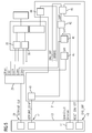
- FIG. 4 shows in greater detail a section of the arrangement FIG. 1 , namely a circuit arrangement 28 which comprises the primary-side controller 13 and the resonant converter 12.
- the controller 13 together with three modules 29,30,31, which will be discussed in more detail below, a drive circuit 34 for driving the resonant converter 12.
- the resonant converter 12 includes a plurality of power electronics components, namely gate driver 35,36, Gates a H-bridge 37 and current transformer 38.
- the individual modules 29, 30, 31, which interact with the controller 13, are a frequency generator 29, a short circuit and resonance error monitoring unit 30, and an idle detection unit 31.
- the short circuit and resonance error monitoring unit 30 is referred to below as a short circuit monitoring unit 30.
- VCO voltage controlled oscillator
- the frequency of the frequency generator 29 is controlled at sufficiently fine intervals and adjustable to reliably be able to prevent a sub-resonant operation of the resonant converter 12 with a change in frequency.
- the short circuit monitoring unit 30 is used to monitor the current flowing through components of the resonant converter 12 current to short circuit.
- the short-circuit monitoring unit 30 is designed as a fast short-circuit responsive module and includes two other relatively slow modules, namely a resonant fault monitoring unit 32 and a resonant trend detection unit 33, so that a total of triple protection against short circuit or medium or long term components of the battery charging system 1 potentially damaging Current changes is given.
- the idle detection unit 31 will be described below FIG. 5 explained in more detail. While the frequency generator 29, which includes a clock generator, connected to a clock terminal 39 of the controller 13 (in FIG. 5 compared to FIG. 4 reduced in size), the short-circuit monitoring unit 30 and its individual modules are 32, 33 in FIG FIG. 5 not shown.
- the idle detection unit 31 As the details of the idle detection unit 31 are in FIG. 5 a filter 40 connected to a PWM terminal 41 of the controller 13, a comparator 42, an RS flip-flop 43, and another filter 44, which is electrically connected to the current transformer 38, recognizable.
- the idle detection unit 31, as shown FIG. 5 shows a cascaded sample and hold circuit 45,46 on.
- the sample and hold circuit 45, 46 is connected to the filter 44 and to the frequency generator 29.
- a signal SH 2 is available, which is applied to the input of an analog-to-digital converter (ADC) 47 of the controller 13.
- ADC analog-to-digital converter
- the controller 13 performs an evaluation, which indicates a possible idling situation of the battery charging system 1 recognizes how using the FIG. 6 and 7 will be described in more detail.
- idling detects the controller 13 stops by a corresponding signal output to the frequency generator 29 and to the gates of the H-bridge 37, the supply of energy in the primary-side winding 6 of the transformer 5.
- This signal flow represents a first, controller-dependent chain of action Idle detection is.
- Another, independent controller chain of action of the shutdown of the battery charging system 1 at idle is constructed in that the output signal SH2 of the sample and hold circuit 45,46 via the comparator 42 to the RS flip-flop 43 is supplied.
- a filtered reference signal SETPOINT_COMP_FLT of a pulse width modulation is applied to the reference input of the comparator 42, which is obtained by means of the filter 40 from an unfiltered reference signal SETPOINT_COMP supplied by the controller 13.
- the shutdown of the resonant converter at idle is effected in this case by a signal directly from the RS flip-flop 43 to the resonant converter 12 signal and is particularly relevant if the first, the controller 13 involving effect chain does not act or not fast enough.
- the interface 48 is also available for resetting the RS flip-flop 43 and therefore referred to as a reset interface.
- the signal SH2 present at the output of the sample and hold circuit 45, 46 is determined at defined times during the clock cycle.
- the current measurement which supplies the signal SH2 is carried out at 90 ° and 270 °.
- a measurement at the end of the clock cycle of the frequency generator 29, that is, at 360 °, on the other hand would provide no useful for the distinction between load and idle case signal.
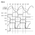
- the FIG. 6 refers to the regular operation, ie charging operation, of the resonant converter 12.
- the total current I_BRIDGE flowing in the resonant converter 12 includes a magnetizing current I_MAGNET, which can not be measured separately and in the top diagram in FIG FIG. 6 outlined in the form of a dashed line.
- Gradients of CGS1, CGS2, CSH1 and CSH2 plotted below the course of the current relate to output signals of the frequency generator 29 FIG. 6 the course of an intermediate signal SH1 transmitted within the sample and hold circuit 45, 46 and the course of the already mentioned output signal SH2 are shown.
- the intermediate signal SH1 is determined at the clock instants 90 ° and 270 °, at which the total current I_BRIDGE is very significantly different from zero, namely near its absolute maximum or minimum.
- the course of SH1 to 90 ° follows the course of the total current I_BRIDGE and is frozen at this time.
- the intermediate signal SH1 held constant up to this point in time is replaced by the current, negative value of I_BRIDGE, which in turn is kept constant.
- the intermediate signal SH1 thus works, triggered by the clock-controlled measurement, as in FIG. 6 is indicated by curved, dashed lines between different parts of the diagram, continuously after every half a cycle between a positive and a negative value.
- the output signal SH2 is kept in the positive range, as from the lowermost portion of FIG. 6 is apparent.
- This positive value of the output signal SH2 becomes permanent to the comparator 42, as shown FIG. 5 already explained, provided.
- the circuit shown can be integrated, for example, in a CPLD (Complex Programmable Logic Device). At least one switching threshold of the idle detection unit 31 can be parameterized in this case, whereby a shutdown of the resonant converter 12 can be triggered.
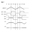
- FIG. 7 which contrary to FIG. 6 illustrates the idle case, clearly the elimination of beyond the magnetizing current I_MAGNET beyond total current I_BRIDGE and the resulting effect on the intermediate signal SH1 and the output signal SH2 recognizable. While the intermediate signal SH1 does not reach the positive range at any one clock time, the output signal SH2 remains constant at zero. The detectable by the idle detection unit 31 difference from regular charging operation ( FIG. 6 ) is thus extremely significant.
- the output signal SH2 is not yet evaluated by the controller 13 until a stable operating state has been reached or, as a prerequisite, the switching threshold of a comparator of the controller 13 for determining a switching criterion is set as a function of the input signal provided to the controller 13.
- the resonant converter 12 stable, diversely operating safety mechanisms against improper operating conditions, both as to high currents, especially short-circuit currents, as well as an open circuit on the secondary side of the transformer 5, available without measurement signals to measure on the secondary side or resort to such ,
Abstract
Eine Schaltungsanordnung (28) umfasst einen in eine primärseitige Wicklung eines Transformators (5) Energie einspeisenden Resonanzwandler (12), sowie eine zu dessen Ansteuerung vorgesehene Ansteuerschaltung (34), welche mehrere Module (29,30,31), nämlich - einen mit variabler Frequenz steuerbaren Frequenzgenerator (29), - eine zum Schutz von Bauteilen des Resonanzwandlers ausgebildete Kurzschlussüberwachungseinheit (30), - eine Leerlauferkennungseinheit (31) aufweist, wobei die Leerlauferkennungseinheit (31) dazu ausgebildet ist, bei Leerlauf einer mit der primärseitigen Wicklung (6) des Transformators (5) zusammenwirkenden Sekundärseite (3) den Resonanzwandler (12) abzuschalten, ohne Informationen von der Sekundärseite (3)zur Verfügung zu haben.A circuit arrangement (28) comprises a resonant converter (12) which feeds energy into a primary-side winding of a transformer (5), and a drive circuit (34) provided for its control, which has a plurality of modules (29, 30, 31) a variable frequency controllable frequency generator (29), a short-circuit monitoring unit (30) designed to protect components of the resonant converter, an idle detection unit (31) having, the idle detection unit (31) is designed to switch off the resonance converter (12) during idling of a secondary side (3) interacting with the primary-side winding (6) of the transformer (5) without having information from the secondary side (3).
Description
Die Erfindung betrifft eine Schaltungsanordnung mit einem Resonanzwandler, insbesondere zum kabellosen Laden eines Elektrofahrzeugs, sowie ein Verfahren zum Betreiben eines Resonanzwandlers.The invention relates to a circuit arrangement with a resonant converter, in particular for wireless charging of an electric vehicle, and a method for operating a resonant converter.
Ein Resonanzwandler ist ein Gleichspannungswandler, welcher mit einem Schwingkreis arbeitet und eine Gleichspannung in eine ein- oder mehrphasige Wechselspannung wandelt. Sofern am Ausgang des Resonanzwandlers keine Gleichrichtung erfolgt, wird dieser auch als Inverter bezeichnet.A resonant converter is a DC-DC converter, which operates with a resonant circuit and converts a DC voltage into a single-phase or multi-phase AC voltage. If no rectification takes place at the output of the resonant converter, this is also referred to as an inverter.
Einfache Bauformen von Invertern, welche jeweils mit einem Paar an Transistoren als Schaltelementen arbeiten, sind beispielsweise aus der
Aus der
Aus der
Der Erfindung liegt die Aufgabe zugrunde, einen Resonanzwandler, welcher zum Einsatz in einem kabellosen Batterieladesystem, insbesondere für Elektrofahrzeuge, geeignet ist, besonders robust gegenüber möglichen Störungen während des Ladevorgangs zu gestalten.The invention has for its object to make a resonant converter, which is suitable for use in a wireless battery charging system, especially for electric vehicles, particularly robust against possible interference during the charging process.
Diese Aufgabe wird erfindungsgemäß gelöst durch eine einen Resonanzwandler umfassende Schaltungsanordnung mit den Merkmalen des Anspruchs 1 sowie durch ein Verfahren zum Betreiben eines Resonanzwandlers mit den Merkmalen des Anspruchs 13. Im Folgenden im Zusammenhang mit der Schaltungsanordnung erläuterte Ausgestaltungen und Vorteile gelten sinngemäß auch für das Verfahren und umgekehrt.This object is achieved by a circuit comprising a resonant converter with the features of claim 1 and by a method for operating a resonant converter with the features of
Die Schaltungsanordnung umfasst einen in eine primärseitige Wicklung eines Transformators Energie einspeisenden Resonanzwandler, sowie eine zu dessen Ansteuerung vorgesehene Ansteuerschaltung, welche mehrere Module, nämlich
- einen mit variabler Frequenz steuerbaren Frequenzgenerator,
- eine zum Schutz von Bauteilen des Resonanzwandlers ausgebildete Kurzschlussüberwachungseinheit, in die bevorzugt auch eine Resonanzfehlerüberwachungseinheit insbesondere zur Erkennung einer Unterresonanz integriert ist, sowie
- eine Leerlauferkennungseinheit, welche dazu ausgebildet ist, bei Leerlauf einer mit der primärseitigen Wicklung des Transformators zusammenwirkenden Sekundärseite ohne Rückmeldung von dieser Sekundärseite den Resonanzwandler abzuschalten. Die Sekundärseite ist in bevorzugter Ausgestaltung mechanisch mit der primärseitigen Wicklung nicht verbunden.
- a variable frequency controllable frequency generator,
- a designed for the protection of components of the resonant converter short circuit monitoring unit, in which preferably also a resonance error monitoring unit is integrated, in particular for detecting a lower resonance, and
- an idle detection unit, which is designed to idle a cooperating with the primary-side winding of the transformer secondary side without feedback from this secondary side of the resonant converter off. In a preferred embodiment, the secondary side is not mechanically connected to the primary-side winding.
Die Erfindung geht von der Überlegung aus, dass sich während des kabellosen Ladens eines Akkumulators Parameter, welche für den Ladevorgang relevant sind, in nicht vorgesehener Weise ändern können. Dies gilt beispielsweise bei einer raschen Änderung der Position des zu ladenden Akkumulators in Relation zur Ladestation oder beim Einbringen von Material in einen Spalt zwischen der Ladestation und demjenigen Objekt, in dem sich der zu ladende Akkumulator befindet.The invention is based on the consideration that during the wireless charging of a rechargeable battery, parameters which are relevant for the charging process can change in an unforeseeable way. This applies, for example, to a rapid change in the position of the accumulator to be charged in relation to the charging station or when introducing material into a gap between the charging station and the object in which the accumulator to be charged is located.
Der ideale Betrieb einer Ladestation, in welchem sich der zu ladende Akkumulator sowie eine im selben Objekt angeordnete sekundärseitige Wicklung in geometrisch exakt bestimmter Relation zur primärseitigen, das heißt Ladestation-seitigen Wicklung befinden, kann somit in der Praxis, insbesondere beim Laden von Elektrofahrzeugen, nur mit speziellen Sicherungsvorkehrungen gewährleistet werden. Solche Sicherungsvorkehrungen könnten zum Beispiel in Form von Fixierungsmechanismen, die Primär- und Sekundärseite des beim Ladevorgang verwendeten Transformators relativ zueinander in unveränderlicher Position halten, bereitgestellt werden.The ideal operation of a charging station, in which the accumulator to be charged as well as a arranged in the same object secondary winding in geometrically exactly determined relation to the primary side, that is charging station side winding, can thus in practice, especially when charging electric vehicles, only be guaranteed with special security measures. Such securing arrangements could be provided, for example, in the form of fixing mechanisms that hold the primary and secondary sides of the transformer used in the charging process in fixed position relative to each other.
Ein anderer Ansatz, Abweichungen vom bestimmungsgemäßen Ladevorgang zu vermeiden oder zumindest rechtzeitig zu detektieren, um Maßnahmen zur Vermeidung unzulässiger Betriebszustände einleiten zu können, liegt in einer permanenten Überwachung sekundärseitiger Betriebsparameter. Beim kabellosen Laden könnte zu diesem Zweck eine Funkverbindung zwischen der Sekundärseite und der Primärseite der gesamten, den Transformator sowie einen diesen mit Energie versorgenden Resonanzwandler umfassenden Anordnung aufgebaut werden. Eine solche Funkverbindung ließe sich mit Komponenten, welche in der Mobilfunktechnik weit verbreitet sind, in rationeller Weise herstellen.Another approach, to avoid deviations from the intended charging process or at least to detect in time to initiate measures to avoid inadmissible operating conditions, lies in a permanent monitoring of secondary operating parameters. In wireless charging, for this purpose, a radio link between the secondary side and the primary side of the entire, the transformer and a comprehensive supplying them with energy resonant converter assembly could be constructed. Such a radio link could be made in a rational manner with components which are widely used in mobile radio technology.
Eine weitere Möglichkeit zum Schutz von sekundärseitigen Komponenten der den Transformator zur Energieübertragung nutzenden, das heißt induktiven, Ladevorrichtung vor Überlastung, insbesondere bei Leerlauf, ist grundsätzlich in Form einer permanenten sekundärseitigen Last zusätzlich zur zu ladenden Batterie gegeben. Auch bei dieser denkbaren Sicherungsmaßnahme wird somit eventuellen sekundärseitigen Betriebsstörungen während des Ladens mit ebenfalls sekundärseitigen Sicherungseinrichtungen begegnet.Another way to protect the secondary components of the transformer for energy transmission, that is inductive, charging device from overload, especially at idle, is basically given in the form of a permanent secondary load in addition to the battery to be charged. Even with this conceivable safety measure, therefore, any secondary-side malfunctioning during charging is also countered with secondary-side safety devices.
Die Erfindung sieht dagegen eine primärseitige Überwachung des Ladevorgangs vor, was sich sowohl auf eine Kurzschlussüberwachung als auch auf eine Leerlaufüberwachung bezieht.By contrast, the invention provides primary-side monitoring of the charging process, which relates both to a short-circuit monitoring and to an open-circuit monitoring.
Die Kurzschlussüberwachung ist im einfachsten Fall ausschließlich zur Sperrung des Resonanzwandlers bei einem Kurzschluss im engsten Sinn ausgebildet. In komplexeren, bevorzugten Ausgestaltungen umfasst die Kurzschlussüberwachungseinheit mehrere, mit unterschiedlicher Trägheit auf Stromänderungen ansprechende, vorzugsweise unabhängig voneinander als Sicherheitseinrichtungen wirksame Module. Insbesondere ist zusätzlich zu einer sehr schnell reagierenden Kurzschlussüberwachungseinheit eine vergleichsweise träge, jedoch bereits bei kleineren Stromänderungen reagierende Resonanzfehlerüberwachungseinheit vorhanden, welche Fehlerzustände des Resonanzwandlers detektiert und diesen gegebenenfalls abschaltet. Die Überwachungseinheit ist daher insbesondere als Kurzschluss- und Resonanzfehlerüberwachungseinheit ausgebildet, nachfolgend kurz als Kurzschlussüberwachungseinheit bezeichnet.The short circuit monitoring is formed in the simplest case exclusively for blocking the resonant converter in a short circuit in the strictest sense. In more complex, preferred embodiments, the short-circuit monitoring unit comprises several, with different inertia responsive to changes in current, preferably independently acting as safety devices modules. In particular, in addition to a very fast-reacting short-circuit monitoring unit, a comparatively sluggish, but already reacting at smaller changes in current resonance error monitoring unit is present, which detects fault conditions of the resonant converter and this switches off, if necessary. The monitoring unit is therefore designed in particular as a short circuit and resonance error monitoring unit, hereinafter referred to as short circuit monitoring unit.
Als drittes Modul, welches im weitesten Sinne der Kurzschlussüberwachungseinheit zugerechnet wird, ist optional eine Resonanztrenderkennungseinheit vorgesehen, welche im Vergleich zur Resonanzfehlerüberwachungseinheit mit nochmals verminderter Reaktionsgeschwindigkeit agiert, jedoch selbst ein langfristiges, schleichendes Abdriften von Betriebsparametern in die Überwachung einbezieht und gegebenenfalls eine Abschaltung des Resonanzwandlers auslöst.As a third module, which is attributed in the broadest sense of the short-circuit monitoring unit, a resonance trend detection unit is optionally provided, which acts in comparison to the resonance error monitoring unit with even reduced reaction rate, but even a long-term, creeping drifting of operating parameters involved in the monitoring and optionally triggers a shutdown of the resonant converter.
Die in jedem Fall zusätzlich zur aus einem oder mehreren Modulen aufgebauten Kurzschlussüberwachungseinheit vorgesehene, primärseitig angeordnete Leerlauferkennungseinheit umfasst in bevorzugter Ausgestaltung eine kaskadierte Sample- und Hold-Schaltung.The in each case in addition to one or more modules constructed short circuit monitoring unit provided, arranged on the primary side idle detection unit comprises in a preferred embodiment, a cascaded sample and hold circuit.
Die Sample- und Hold-Schaltung ist ausgangsseitig vorzugsweise mit einem Eingang eines zur Ansteuerung des Resonanzwandlers vorgesehenen Controllers verbunden. Derselbe Controller steuert in vorteilhafter Ausführungsform auch den Frequenzgenerator an, welcher der Ansteuerschaltung zuzurechnen ist und den Resonanzwandler während des Ladevorgangs im überresonanten Betrieb hält. Im Fall eines detektierten, auf der Sekundärseite auftretenden Leerlaufs erfolgt die Detektion ausschließlich auf der Primärseite und damit galvanisch getrennt von den vom Leerlauf direkt betroffenen Bauteilen. Der Controller erhält hierbei von der Sample- und Hold-Schaltung ein analoges Eingangssignal und damit eine Maßzahl für ein Verhältnis zwischen einem Leerlaufbetrieb und einem Lastbetrieb. Über den Frequenzgenerator bzw. ein H-Brücken Ansteuersignal sorgt der Controller für eine Abschaltung des Resonanzwandlers. Der Controller weist hierzu eine eigene interne Schaltschwelle auf, die beispielsweise softwaretechnisch festgelegt ist. Auf diese Weise ist eine erste, Controller-abhängige Wirkkette der Leerlaufüberwachung realisiert.On the output side, the sample and hold circuit is preferably connected to an input of a controller provided for driving the resonant converter. The same controller controls in an advantageous embodiment, the frequency generator, which is attributable to the drive circuit and holds the resonant converter during the charging in over-resonant operation. In the case of a detected idling occurring on the secondary side, the detection takes place exclusively on the primary side and thus galvanically separated from the components directly affected by the idling. The controller receives from the sample and hold circuit an analog input signal and thus a measure of a relationship between an idle mode and a load operation. Via the frequency generator or an H-bridge drive signal, the controller ensures a shutdown of the resonant converter. For this purpose, the controller has its own internal switching threshold, which is determined, for example, by software technology. In this way, a first, controller-dependent chain of action idle monitoring is realized.
Der Sample- und Hold-Schaltung sind optional ein Komparator sowie ein Flip-Flop, insbesondere ein RS-Flip-Flop, nachgeschaltet, wobei ein Referenzeingang des Komparators über einen einer PWM-Einheit (Pulsweiten-Modulations- Einheit) nachgeschalteten Filter mit dem Controller verbunden ist, während der zweite Eingang des Komparators mit dem Ausgang der kaskadierten Sample- und Hold-Schaltung verbunden ist. Eingänge des Flip-Flops sind hierbei zum einen an den Ausgang des Komparators und zum anderen an eine Reset-Schnittstelle des zur Ansteuerung des Resonanzwandlers vorgesehenen Controllers angeschlossen.The sample and hold circuit are optionally a comparator and a flip-flop, in particular an RS flip-flop, connected downstream, wherein a reference input of the comparator via a PWM unit (pulse width modulation unit) downstream filter with the controller while the second input of the comparator is connected to the output of the cascaded sample and hold circuit. Inputs of the flip-flop are on the one hand to the output of the comparator and on the other hand connected to a reset interface of the controller provided for driving the resonant converter.
Ein Ausgang des Flip-Flops ist vorzugsweise direkt mit einem Eingang eines zur Einspeisung von Leistung in die primärseitige Wicklung des Transformators vorgesehenen Gate-Treibers, welcher eine Komponente des Resonanzwandlers ist, verbunden. Auf diese Weise ist mittels des Flip-Flops eine vom Controller unabhängig auslösende Abschaltung des Resonanzwandlers ermöglicht. Zur Unterscheidung von der zuvor genannten Controller-abhängigen Wirkkette wird im Fall einer solchen Abschaltung über das Flip-Flop von einer Controller-unabhängigen Wirkkette gesprochen. Die das Flip-Flop umfassende Leerlauferkennungseinheit überwacht hierbei, nachdem sie einmalig mittels des Controllers parametriert wurde, selbsttätig den Leerlaufpunkt und arbeitet hierbei asynchron zum Controller. Anders ausgedrückt: Die verschiedenen Wirkketten der Leerlauferkennung unterscheiden sich hinsichtlich ihrer Taktung voneinander. Die Asynchronität bezieht sich in diesem Zusammenhang auf eine Arbeitsfrequenz einer leistungselektronischen Brückenschaltung des Resonanzwandlers im Verhältnis zur Arbeitsfrequenz des Controllers. Ein asynchrones Auslösen der Leerlaufdetektion mittels des Flip-Flops wäre außerdem auch bei einer eventuellen Fehlfunktion des Controllers gegeben.An output of the flip-flop is preferably connected directly to an input of a gate driver intended for feeding power into the primary-side winding of the transformer, which is a component of the resonant converter. In this way, by means of the flip-flop independent triggering of the controller shutdown of the resonant converter allows. In order to distinguish from the aforementioned controller-dependent chain of action in the case of such a shutdown on the flip-flop is spoken by a controller-independent chain of action. The idling recognition unit comprising the flip-flop automatically monitors the idling point after it has been parameterized once by means of the controller and works asynchronously with the controller. In other words, the different chains of action of idle detection differ from each other in terms of their timing. The asynchronicity in this context refers to an operating frequency of a power electronic bridge circuit of the resonant converter in relation to the operating frequency of the controller. An asynchronous triggering of the idle detection by means of the flip-flop would also be given in case of a malfunction of the controller.
In vorteilhafter Ausgestaltung ist ein weiterer Ausgang des Flip-Flops direkt mit dem zur Ansteuerung des Resonanzwandlers vorgesehenen Controller verbunden. Mit dieser Rückmeldung des Flip-Flops an den Controller ist eine Funktionskontrolle von Komponenten der Leerlauferkennungseinheit gegeben.In an advantageous embodiment, a further output of the flip-flop is connected directly to the controller provided for driving the resonant converter. With this feedback of the flip-flop to the controller is a function control of components of the idle detection unit is given.
Selbst mit dieser Zusatzfunktion zeichnet sich die gesamte Schaltungsanordnung durch einen einfachen Aufbau, insbesondere den Entfall aufwändiger Sensorik zur Erkennung des Leerlauf-Betriebs, aus.Even with this additional function, the entire circuit arrangement is characterized by a simple structure, in particular the elimination of complex sensors for detecting the idling operation from.
Das Verfahren zum Betreiben eines Resonanzwandlers, welcher in eine primärseitige Wicklung eines Transformators, insbesondere einer Ladestation zum kabellosen Laden eines elektrisch angetriebenen Fahrzeugs, Energie einspeist, umfasst in vorteilhafter Weise folgende Merkmale:
- Der Resonanzwandler wird im überresonanten Bereich betrieben und bevorzugt hinsichtlich Resonanzpunkt sowie Strom zur Vermeidung eines Unterresonanzbetriebes überwacht,
- die Ansteuerung des Resonanzwandlers erfolgt mittels eines Controllers,
- ein sekundärseitiger Leerlauf des Transformators wird primärseitig asynchron zum Controller überwacht, wobei bei Leerlaufdetektion eine Controller-unabhängige Abschaltung des Resonanzwandlers erfolgt.
- The resonant converter is operated in the over-resonant range and preferably monitored with respect to the resonance point and current to avoid a low-resonance operation,
- the control of the resonant converter by means of a controller,
- a secondary-side idling of the transformer is monitored asynchronously to the primary side of the controller, wherein at idle detection is a controller-independent shutdown of the resonant converter.
Gemäß einer vorteilhaften Weiterbildung des Verfahrens erfolgt eine zusätzliche Leerlaufdetektion unter Einbeziehung des Controllers. Hierbei reagiert die den Controller nutzende Leerlaufdetektion vorzugsweise träger als die vom Controller unabhängige Leerlaufdetektion. Die vergleichsweise träge ansprechende Leerlauferkennung durch den Controller hat den Vorteil, dass auch bei langsam und sich stetig ändernder Last im Batterieladesystem, sofern dies zu einer Überlastung von Komponenten, insbesondere leistungselektronischen Elementen, führen könnte, der Resonanzwandler abgeschaltet bzw. in seiner Betriebsart verändert wird.According to an advantageous embodiment of the method, an additional idle detection takes place with the involvement of the controller. In this case, the idle detection using the controller preferably reacts more slowly than the idle detection independent of the controller. The relatively sluggishly responsive idle detection by the controller has the advantage that even with slow and constantly changing load in the battery charging system, if this could lead to an overload of components, especially power electronic elements, the resonant converter is switched off or changed in its mode.
Die Leerlaufdetektion erfolgt vorzugsweise mit mindestens einer einstellbaren Schaltschwelle. Sofern mehrere Abschaltmechanismen, die bei Leerlauf oder anderen unzulässigen Laständerungen greifen, vorhanden sind, können in vorteilhafter Ausgestaltung unterschiedliche Parameter der Leerlaufdetektion unabhängig voneinander eingestellt werden, wobei der Begriff Leerlaufdetektion in einem weiten Sinne zu verstehen ist und auch langsame Laständerungen einschließt.The idle detection is preferably carried out with at least one adjustable switching threshold. If a plurality of shutdown mechanisms that intervene at idle or other impermissible load changes, are present, different parameters of the idle detection can be set independently in an advantageous embodiment, the term idle detection is to be understood in a broad sense and includes slow load changes.
Zur schnell ansprechenden Leerlaufdetektion wird während jeder vollen Periode eines primärseitigen Stromsignals vorzugsweise mehrfach ein Strommesswert erfasst und zumindest in einem Teilzeitraum bis zur Erfassung des nächsten Strommesswertes stabil gehalten. Beispielsweise werden Strommesswerte zweifach während jeder vollen Periode des primärseitigen Stromsignals, insbesondere bei 90° und 270°, erfasst. Die Erfassung bei 90° und 270° hat den Vorteil, dass zu diesen Taktzeitpunkten der gesamte primärseitige Strom einschließlich Magnetisierungsstrom im bestimmungsgemäßen Ladebetrieb maximal oder zumindest nahe am Maximum ist, während zu denselben Taktzeitpunkten im Leerlauffall der Magnetisierungsstrom jeweils im Nulldurchgang ist und kein zusätzlicher Strom gegeben ist, so dass insgesamt der Leerlauffall sehr gut detektierbar ist.For fast response idle detection, it is preferable during each full period of a primary-side current signal recorded a current reading several times and kept stable at least in a sub-period until the detection of the next measured current value. For example, measured current values are detected twice during each full period of the primary-side current signal, in particular at 90 ° and 270 °. The detection at 90 ° and 270 ° has the advantage that at these cycle times, the total primary side current including magnetizing current in the normal charging mode is at or near maximum, while at the same cycle times in idle the magnetizing current is at zero crossing and no additional current is, so that the total idle case is very well detectable.
Jeder Strommesswert, das heißt insbesondere sowohl der bei 90° als auch der bei 270° erfasste Strommesswert, wird in ein vorzugsweise analoges Ausgangssignal gewandelt, welches in besonders bevorzugter Weise mindestens solange konstant gehalten wird, bis der nächste Strommesswert erfasst wird. Somit liegt jedes derartige Ausgangssignal vorzugsweise unverändert über mindestens 180° an.Each measured current value, that is, in particular both the measured current value at 90 ° and at 270 °, is converted into a preferably analog output signal, which is kept constant in a particularly preferred manner at least until the next current measured value is detected. Thus, each such output signal preferably remains unchanged over at least 180 °.
Nachfolgend wird ein Ausführungsbeispiel der Erfindung anhand einer Zeichnung näher erläutert. Hierin zeigen, teilweise in grober Vereinfachung:
- FIG 1
- in einem Blockdiagramm ein Batterieladesystem zum kabellosen Laden einer Batterie mit einem Resonanzwandler,
- FIG 2
- in einer vereinfachten Darstellung das Batterieladesystem nach
FIG 1 mit veranschaulichtem Regelkreis, - FIG 3
- eine weitere vereinfachte Darstellung des Batterieladesystems nach
FIG 1 , wobei hier die zu detektierende Leerlaufsituation verdeutlicht ist, - FIG 4
- eine innerhalb des Batterieladesystems nach
FIG 1 vorgesehene Schaltungsanordnung, welche den Resonanzwandler sowie eine Ansteuerschaltung zu dessen Ansteuerung umfasst, inklusive der Schutz- und Überwachungsmechanismen, - FIG 5
- die Schaltungsanordnung nach
FIG 4 mit im Vergleich zuFIG 4 detaillierterer Darstellung eines Moduls, nämlich einer Leerlauferkennungseinheit, - FIG 6
- in Diagrammform Spannungs-, Strom- sowie SignalVerläufe im bestimmungsgemäßen Betrieb des Batterieladesystems nach
FIG 1 , - FIG 7
- in einer Darstellung analog
FIG 6 den Leerlaufbetrieb des Batterieladesystems nachFIG 1 .
- FIG. 1
- in a block diagram a battery charging system for wireless charging of a battery with a resonant converter,
- FIG. 2
- in a simplified representation of the battery charging system
FIG. 1 with illustrated control loop, - FIG. 3
- a further simplified illustration of the battery charging system according to
FIG. 1 , where the idling situation to be detected is illustrated here, - FIG. 4
- one within the battery charging system
FIG. 1 provided circuit arrangement which the resonant converter and a drive circuit for its control includes, including the protection and monitoring mechanisms, - FIG. 5
- the circuit according to
FIG. 4 with compared toFIG. 4 a more detailed representation of a module, namely an idle detection unit, - FIG. 6
- in diagram form voltage, current and signal waveforms during normal operation of the battery charging system
FIG. 1 . - FIG. 7
- in a representation analog
FIG. 6 idle operation of the battery charging systemFIG. 1 ,
Einander entsprechende Teile oder Parameter sind in allen Figuren mit den gleichen Bezugszeichen gekennzeichnet.Corresponding parts or parameters are identified in all figures with the same reference numerals.
Ein insgesamt mit dem Bezugszeichen 1 gekennzeichnetes, in
Die Schnittstelle zwischen der Primärseite 2 und der Sekundärseite 3 ist gebildet durch einen Transformator 5 mit einer primärseitigen Wicklung 6, das heißt Primärspule, und einer sekundärseitigen Wicklung 7.The interface between the
Die Primärseite 2 des Batterieladesystems 1 umfasst weiter einen Gleichrichter 8, einen Leistungsfaktorkorrekturfilter 9 (PFC = Power Factor Correction), einen Zwischenkreis 10 (DC-Link), sowie einen Verstärker 11, welcher elektrische Leistung einem Resonanzwandler 12 zuführt, der mit einem Schwingkreis arbeitet, dessen Resonanzfrequenz unter anderem von der Induktivität und der (Kompensations-)Kapazität der primärseitigen Wicklung 6 des Transformators 5 abhängt.The
Der Resonanzwandler 12 arbeitet mit Frequenzen oberhalb von 50 kHz und wird angesteuert mit Hilfe eines Controllers 13, welcher sich ebenfalls auf der Primärseite 2 des Batterieladesystems 1 befindet. Der Controller 13 spielt eine wesentliche Rolle bei der Erkennung einer Leerlaufsituation, das heißt des plötzlichen unbeabsichtigten Abklemmens der Batterie 4, wie im Folgenden noch im Detail erläutert wird. Auf der Primärseite 2 sind weiterhin sind ein primärseitiger Stromsensor 14 sowie ein primärseitiger Spannungssensor 15 vorhanden. Eine Kommunikationseinheit 16 ist zum Austausch von Daten, etwa mit einem übergeordneten Controller, vorgesehen. Ein zusätzliches, Kommunikationselement 17 ist für Kalibrierungs- und Kontrollzwecke insbesondere in Zusammenarbeit mit einer entsprechenden Kommunikationseinheit 25 auf der Sekundärseite 3 verwendbar. Die Kommunikation erfolgt drahtlos, beispielsweise über WLAN. Weitere Komponenten der Primärseite 2 sind eine Spannungsversorgung 18 und eine Lüftersteuerung 19.The
Auf der Sekundärseite 3 befinden sich, der sekundärseitigen Wicklung 7 nachgeschaltet, eine Kapazität 20 sowie ein Gleichrichter 21. Ähnlich wie die Primärseite 2 weist auch die Sekundärseite 3 einen Controller 22, einen Stromsensor 23, sowie einen Spannungssensor 24 auf. Analog zum primärseitigen Kommunikationselement 17 ist auf der Sekundärseite 3 das bereits erwähnte Kommunikationselement 25 insbesondere für die Kalibrierungs- und Kontrollzwecke vorgesehen. Statt einer Kommunikationseinheit 16 ist auf der Sekundärseite 3 ein in das Fahrzeug eingebautes Fahrzeugkommunikationselement 26 vorhanden. Anstelle einer eine Wechselspannung liefernden Spannungsversorgung 18, wie auf der Primärseite 2 vorgesehen, weist die Sekundärseite 3 lediglich eine Hilfsspannungsversorgung 27 auf.On the
Grundzüge der Regelung des Batterieladesystems 1 sind in
In
Die
Bei den einzelnen Modulen 29,30,31, welche mit dem Controller 13 zusammenwirken, handelt es sich um einen Frequenzgenerator 29, eine Kurzschluss- und Resonanzfehlerüberwachungseinheit 30, sowie eine Leerlauferkennungseinheit 31. Die Kurzschlussund Resonanzfehlerüberwachungseinheit 30 wird nachfolgend vereinfacht als Kurzschlussüberwachungseinheit 30 bezeichnet.The
Der Frequenzgenerator 29 (Dual Phase Frequency Generator) ist für den Betrieb des Resonanzwandlers 12 erforderlich und umfasst einen vom Controller 13 aus gesteuerten, digital oder analog aufgebauten, in der Frequenz steuerbaren Generator, welcher als spannungsgesteuerter Oszillator (VCO = voltage controlled oscillator) oder als digitaler Frequenzteiler ausgebildet ist, auf. Die Frequenz des Frequenzgenerators 29 ist in hinreichend feinen Intervallen steuer- und regelbar, um zuverlässig einen unterresonanten Betrieb des Resonanzwandlers 12 bei einer Änderung der Frequenz verhindern zu können.The frequency generator 29 (Dual Phase Frequency Generator) is required for the operation of the
Die Kurzschlussüberwachungseinheit 30 dient der Überwachung des durch Komponenten des Resonanzwandlers 12 fließenden Stromes auf Kurzschluss. Die Kurzschlussüberwachungseinheit 30 ist als schnell auf Kurzschluss ansprechendes Modul ausgebildet und schließt zwei weitere, relativ träge Module, nämlich eine Resonanzfehlerüberwachungseinheit 32und eine Resonanztrenderkennungseinheit 33, ein, so dass insgesamt eine dreifache Absicherung gegen Kurzschluss oder mittel- beziehungsweise langfristige, Komponenten des Batterieladesystems 1 potentiell schädigende Stromänderungen gegeben ist.The short
Die Leerlauferkennungseinheit 31 wird im Folgenden anhand
Als Einzelheiten der Leerlauferkennungseinheit 31 sind in
Eingangsseitig ist die Sample&Hold-Schaltung 45,46 mit dem Filter 44 sowie mit dem Frequenzgenerator 29 verbunden. Am Ausgang der kaskadierten Sample&Hold-Schaltung 45,46 steht ein Signal SH2 zur Verfügung, welches an den Eingang eines Analog-Digital-Wandlers (ADC) 47 des Controllers 13 gelegt wird. Mit Hilfe des durch den Analog-Digital-Wandler 47 digitalisierten Signals nimmt der Controller 13 eine Auswertung vor, die eine eventuelle Leerlaufsituation des Batterieladesystems 1 erkennt, wie anhand der
Eine weitere, Controller-unabhängige Wirkkette der Abschaltung des Batterieladesystems 1 bei Leerlauf ist dadurch aufgebaut, dass das Ausgangssignal SH2 der Sample&Hold-Schaltung 45,46 über den Komparator 42 dem RS-Flip-Flop 43 zugeführt wird. An den Referenzeingang des Komparators 42 ist hierbei ein gefiltertes Referenzsignal SETPOINT_COMP_FLT einer Pulsweitenmodulation gelegt, welches mittels des Filters 40 aus einem vom Controller 13 gelieferten ungefilterten Referenzsignal SETPOINT_COMP gewonnen wird. Die Abschaltung des Resonanzwandlers bei Leerlauf wird in diesem Fall durch ein direkt vom RS-Flip-Flop 43 an den Resonanzwandler 12 geleitetes Signal bewirkt und kommt insbesondere dann zum Tragen, wenn die erste, den Controller 13 einbeziehende Wirkkette nicht oder nicht schnell genug wirkt.Another, independent controller chain of action of the shutdown of the battery charging system 1 at idle is constructed in that the output signal SH2 of the sample and hold
Zusätzlich ist ein Ausgang des RS-Flip-Flops 43 mit einer Schnittstelle 48 (GPIO = General Purpose Input/Output) des Controllers 13 verbunden. Mit dieser Rückmeldung des RS-Flip-Flops 43 an den Controller 13 ist eine ergänzende Kontrollfunktion gegeben. Die Schnittstelle 48 ist darüber hinaus auch zur Rücksetzung des RS-Flip-Flops 43 nutzbar und deshalb als Reset-Schnittstelle bezeichnet.In addition, an output of the RS flip-
Das am Ausgang der Sample&Hold-Schaltung 45,46 anliegende Signal SH2 wird zu definierten Zeitpunkten während des Taktzyklus ermittelt. Um den Leerlauf des Transformators 5, bei welchem nur ein Magnetisierungsstrom auftritt, bestmöglich vom Lastfall, in dem zusätzlich ein Laststrom gegeben ist, unterscheiden zu können, wird die Strommessung, welche das Signal SH2 liefert, bei 90° und 270° durchgeführt. Eine Messung am Ende des Taktzyklus des Frequenzgenerators 29, das heißt bei 360°, würde dagegen kein für die Unterscheidung zwischen Last- und Leerlauffall nutzbares Signal liefern.The signal SH2 present at the output of the sample and hold
Zur weiteren Erläuterung der im Rahmen der Leerlaufdetektion durchgeführten Messungen wird im Folgenden auf die
Die
Das Zwischensignals SH1 wird zu den Taktzeitpunkten 90° und 270°, zu welchen der Gesamtstrom I_BRIDGE jeweils sehr signifikant ungleich Null, nämlich nahe seines absoluten Maximums beziehungsweise Minimums, ist, ermittelt. Hierbei folgt der Verlauf von SH1 bis 90° dem Verlauf des Gesamtstroms I_BRIDGE und wird zu diesem Zeitpunkt eingefroren. Zum Taktzeitpunkt 270° wird das bis zu diesem Zeitpunkt konstant gehaltene Zwischensignal SH1 durch den aktuellen, negativen Wert von I_BRIDGE ersetzt, welcher wiederum konstant gehalten wird. Das Zwischensignal SH1 klappt somit, ausgelöst durch die taktgesteuerte Messung, wie in
Dieser positive Wert des Ausgangssignals SH2 wird permanent dem Komparator 42, wie anhand
In
Insgesamt stellt der Resonanzwandler 12 stabile, diversitär arbeitende Sicherungsmechanismen gegen unzulässige Betriebszustände, sowohl was zu hohe Ströme, insbesondere Kurzschlussströme, als auch einen Leerlauf auf der Sekundärseite des Transformators 5 betrifft, zur Verfügung ohne hierzu Messsignale auf der Sekundärseite zu messen bzw. auf solche zurückzugreifen.Overall, the
Claims (19)
die Leerlauferkennungseinheit (31) dazu ausgebildet ist, bei Leerlauf einer mit der primärseitigen Wicklung (6) des Transformators (5) zusammenwirkenden Sekundärseite (3) ohne Rückmeldung von der Sekundärseite (3) den Resonanzwandler (12) abzuschalten.Circuit arrangement (28), in particular for a cordless battery charging system (1), preferably of an electric vehicle, comprising a resonant converter (12) feeding energy into a primary-side winding of a transformer (5), and a drive circuit (34) provided for its control, which has a plurality of modules (29 , 30,31), namely
the idle detection unit (31) is designed to switch off the resonant converter (12) during idling of a secondary side (3) cooperating with the primary-side winding (6) of the transformer (5) without feedback from the secondary side (3).
dadurch gekennzeichnet, dass die Leerlauferkennungseinheit (31) eine kaskadierte Sample- und Hold-Schaltung (45,46) umfasst.Circuit arrangement (28) according to Claim 1,
characterized in that the idle detection unit (31) comprises a cascaded sample and hold circuit (45,46).
dadurch gekennzeichnet, dass die Sample- und Hold-Schaltung (45,46) ausgangsseitig mit einem Eingang eines zur Ansteuerung des Resonanzwandlers (12) vorgesehenen Controllers (13) verbunden ist.Circuit arrangement (28) according to Claim 2,
characterized in that the sample and hold circuit (45, 46) is connected on the output side to an input of a controller (13) provided for driving the resonant converter (12).
dadurch gekennzeichnet, dass die Leerlauferkennungseinheit (31), der Sample- und Hold-Schaltung nachgeschaltet, einen Komparator (42) sowie ein Flip-Flop (43) aufweist.Circuit arrangement (28) according to Claim 2 or 3,
characterized in that the idle detection unit (31), the sample and hold circuit connected downstream, a comparator (42) and a flip-flop (43).
dadurch gekennzeichnet, dass das Flip-Flop (43) als RS-Flip-Flop ausgebildet ist.Circuit arrangement (28) according to Claim 4,
characterized in that the flip-flop (43) is designed as an RS flip-flop.
dadurch gekennzeichnet, dass ein Ausgang des Flip-Flops (43) direkt mit einem Eingang eines zur Einspeisung von Leistung in die primärseitige Wicklung (6) des Transformators vorgesehenen Gate-Treibers (35,36) verbunden ist.Circuit arrangement (28) according to Claim 4 or 5, characterized
characterized in that an output of the flip-flop (43) is connected directly to an input of a gate driver (35, 36) provided for supplying power to the primary-side winding (6) of the transformer.
dadurch gekennzeichnet, dass ein weiterer Ausgang des Flip-Flops (43) direkt mit dem zur Ansteuerung des Resonanzwandlers (12) vorgesehenen Controller (13) verbunden ist.Circuit arrangement (28) according to Claim 6,
characterized in that a further output of the flip-flop (43) is connected directly to the controller (13) provided for driving the resonant converter (12).
dadurch gekennzeichnet, dass ein Eingang des Flip-Flops mit einer Schnittstelle (48) des zur Ansteuerung des Resonanzwandlers (12) vorgesehenen Controllers (13) verbunden ist.Circuit arrangement (28) according to one of Claims 4 to 7,
characterized in that an input of the flip-flop with an interface (48) of the intended for driving the resonant converter (12) controller (13) is connected.
dadurch gekennzeichnet, dass die Leerlauferkennungseinheit (31) mehrere, sich hinsichtlich ihrer Taktung voneinander unterscheidende Wirkketten umfasst.Circuit arrangement (28) according to one of Claims 1 to 8,
characterized in that the idle detection unit (31) comprises a plurality of mutually different with respect to their timing chains of action.
dadurch gekennzeichnet, dass die Kurzschlussüberwachungseinheit (30) mehrere, mit unterschiedlicher Trägheit auf Stromänderungen ansprechende Module (32,33) umfasst.Circuit arrangement (28) according to one of Claims 1 to 9,
characterized in that the short circuit monitoring unit (30) comprises a plurality of modules (32, 33) responsive to current changes with different inertia.
dadurch gekennzeichnet, dass eine zusätzliche Leerlaufdetektion unter Nutzung des Controllers (13) erfolgt.Method according to claim 13,
characterized in that an additional idle detection using the controller (13) takes place.
dadurch gekennzeichnet, dass die den Controller (13) nutzende Leerlaufdetektion träger als die Controller-unabhängige Leerlaufdetektion erfolgt.Method according to claim 14,
characterized in that the controller (13) using idle detection carrier is carried out as the controller-independent idle detection.
dadurch gekennzeichnet, dass die Leerlaufdetektion mit mindestens einer einstellbare Schaltschwelle erfolgt.Method according to one of claims 13 to 15,
characterized in that the idle detection is carried out with at least one adjustable switching threshold.
dadurch gekennzeichnet, dass zur Leerlaufdetektion während jeder vollen Periode eines primärseitigen Stromsignals (I_BRIDGE) mehrfach ein Strommesswert erfasst und hieraus ein Signal (SH1,SH2) generiert wird, welches zumindest in einem Teilzeitraum bis zur Erfassung des nächsten Strommesswertes stabil gehalten wird.Method according to one of claims 13 to 16,
characterized in that for idle detection during each full period of a primary-side current signal (I_BRIDGE) several times a current reading is detected and from this a signal (SH1, SH2) is generated, which is kept stable at least in a sub-period until detection of the next current reading.
dadurch gekennzeichnet, dass Strommesswerte zweifach während jeder vollen Periode des primärseitigen Stromsignals (I_BRIDGE), insbesondere bei 90° und 270°, erfasst und hieraus ein Zwischensignal (SH1) sowie ein Ausgangssignal (SH2) generiert werden.Method according to claim 17,
characterized in that current readings are detected twice during each full period of the primary-side current signal (I_BRIDGE), in particular at 90 ° and 270 °, and from this an intermediate signal (SH1) and an output signal (SH2) are generated.
dadurch gekennzeichnet, dass das aus dem Strommesswert (I_BRIDGE) generierte Ausgangssignal (SH2) zumindest solange konstant gehalten wird, bis der nächste Strommesswert (I_BRIDGE) erfasst wird.Method according to claim 18,
characterized in that the output signal (SH2) generated from the current measurement value (I_BRIDGE) is kept constant at least until the next current measurement value (I_BRIDGE) is detected.
Applications Claiming Priority (1)
| Application Number | Priority Date | Filing Date | Title |
|---|---|---|---|
| DE102013207883.8A DE102013207883A1 (en) | 2013-04-30 | 2013-04-30 | Circuit arrangement with a resonant converter and method for operating a resonant converter |
Publications (2)
| Publication Number | Publication Date |
|---|---|
| EP2800233A1 true EP2800233A1 (en) | 2014-11-05 |
| EP2800233B1 EP2800233B1 (en) | 2016-11-16 |
Family
ID=50189594
Family Applications (1)
| Application Number | Title | Priority Date | Filing Date |
|---|---|---|---|
| EP14157472.3A Not-in-force EP2800233B1 (en) | 2013-04-30 | 2014-03-03 | Circuit arrangement with a resonance converter and method for operating a resonance converter |
Country Status (4)
| Country | Link |
|---|---|
| US (1) | US9608530B2 (en) |
| EP (1) | EP2800233B1 (en) |
| CN (1) | CN104134969B (en) |
| DE (1) | DE102013207883A1 (en) |
Cited By (1)
| Publication number | Priority date | Publication date | Assignee | Title |
|---|---|---|---|---|
| NL2020659B1 (en) * | 2018-03-23 | 2019-10-02 | Prodrive Tech Bv | Contactless power transfer system with safety feature and operating method thereof |
Families Citing this family (10)
| Publication number | Priority date | Publication date | Assignee | Title |
|---|---|---|---|---|
| CN104081625B (en) * | 2012-02-03 | 2017-09-22 | 株式会社村田制作所 | Switching power unit |
| CN106558999B (en) * | 2015-09-30 | 2020-02-14 | 株式会社村田制作所 | DC/DC converter |
| US20170117813A1 (en) * | 2015-10-21 | 2017-04-27 | Quanta Computer Inc. | Method and system for testing a power supply unit |
| GB2546787A (en) * | 2016-01-29 | 2017-08-02 | Bombardier Primove Gmbh | A system and a method for deactivating an inductive power transfer and a secondary unit |
| EP3220505B8 (en) * | 2016-03-16 | 2018-10-31 | Blue Inductive GmbH | Inductive power transfer control |
| US10245960B2 (en) | 2016-03-17 | 2019-04-02 | Denso International America, Inc. | Electric power converter device |
| US10427532B2 (en) * | 2017-04-05 | 2019-10-01 | Ford Global Technologies, Llc | On-board and wireless vehicle charging systems with shared components |
| DE102017208595A1 (en) | 2017-05-22 | 2018-11-22 | Audi Ag | Contactless motor vehicle charging device, component of a contactless motor vehicle charging device, method for controlling a contactless motor vehicle charging device and a motor vehicle with a contactless motor vehicle charging device |
| US10763751B2 (en) * | 2018-06-12 | 2020-09-01 | Sanken Electric Co., Ltd. | Device and method for converting input voltage to output voltage |
| US20210268920A1 (en) * | 2018-06-29 | 2021-09-02 | Brusa Elektronik Ag | Inductive Charging of Vehicles with Secondary-Side Voltage Measurement and Feedback from the Secondary Side to the Primary Side |
Citations (12)
| Publication number | Priority date | Publication date | Assignee | Title |
|---|---|---|---|---|
| US2783384A (en) | 1954-04-06 | 1957-02-26 | Westinghouse Electric Corp | Electrical inverter circuits |
| WO1994028560A1 (en) * | 1993-05-21 | 1994-12-08 | Era Patents Limited | Power coupling |
| EP0758153A2 (en) * | 1995-08-07 | 1997-02-12 | Aspro Technology Ag | Circuit device for disconnecting a transformer not under load |
| EP0820653B1 (en) | 1995-04-10 | 1999-06-02 | Norvik Traction Inc. | Traction battery charging with inductive coupling |
| EP0982831A2 (en) * | 1998-08-19 | 2000-03-01 | NOKIA TECHNOLOGY GmbH | Charging arrangement using inductive energy transfer for batteries in a mobile device |
| EP1432097A1 (en) * | 2003-10-06 | 2004-06-23 | Siemens Aktiengesellschaft | Charging apparatus and method for contactless charging of a mobile unit |
| JP2006230032A (en) * | 2005-02-15 | 2006-08-31 | Noboru Daiho | Power transmitter and power transmissison method |
| EP1962403A2 (en) * | 2007-02-20 | 2008-08-27 | Seiko Epson Corporation | Power transmission control device, power transmission system, electronic instrument, and non-contact power transmission system |
| EP2079144A2 (en) * | 2008-01-09 | 2009-07-15 | Seiko Epson Corporation | Power transmission control device, power transmitting device, non-contact power transmission system, electronic instrument, and power transmission control method |
| DE102008027126A1 (en) | 2008-06-06 | 2009-12-10 | BSH Bosch und Siemens Hausgeräte GmbH | Method for operating a resonant circuit with at least two electronic switches and resonant circuit |
| US20110074346A1 (en) * | 2009-09-25 | 2011-03-31 | Hall Katherine L | Vehicle charger safety system and method |
| WO2012058466A1 (en) * | 2010-10-29 | 2012-05-03 | Qualcomm Incorporated | Wireless energy transfer via coupled parasitic resonators |
Family Cites Families (9)
| Publication number | Priority date | Publication date | Assignee | Title |
|---|---|---|---|---|
| US5315496A (en) * | 1990-01-29 | 1994-05-24 | Kabushiki Kaisha Toshiba | Current resonance converter having overload detecting function |
| US6807070B2 (en) * | 2001-12-12 | 2004-10-19 | International Rectifier Corporation | Resonant converter with phase delay control |
| WO2005106901A2 (en) * | 2004-05-04 | 2005-11-10 | Philips Intellectual Property & Standards Gmbh | A wireless powering device, an energizable load, a wireless system and a method for a wireless energy transfer |
| US7561452B2 (en) * | 2005-11-28 | 2009-07-14 | Supertex, Inc. | Transformer-isolated flyback converters and methods for regulating output current thereof |
| JP4752484B2 (en) * | 2005-12-14 | 2011-08-17 | サンケン電気株式会社 | DC-DC converter |
| JP5544705B2 (en) * | 2008-01-09 | 2014-07-09 | セイコーエプソン株式会社 | Power transmission control device, power transmission device, non-contact power transmission system, electronic device, and power transmission control method |
| CA2718901C (en) * | 2008-03-17 | 2018-10-16 | Powermat Ltd. | Inductive transmission system |
| US9350252B2 (en) * | 2008-10-21 | 2016-05-24 | On-Bright Electronics (Shanghai) Co., Ltd. | Systems and methods for protecting power conversion systems based on at least feedback signals |
| DE102012007449B4 (en) * | 2012-04-13 | 2024-02-22 | Tridonic Gmbh & Co Kg | Method for operating an LLC resonant converter for a lamp, converter and LED converter |
-
2013
- 2013-04-30 DE DE102013207883.8A patent/DE102013207883A1/en not_active Withdrawn
-
2014
- 2014-03-03 EP EP14157472.3A patent/EP2800233B1/en not_active Not-in-force
- 2014-04-28 CN CN201410175570.4A patent/CN104134969B/en not_active Expired - Fee Related
- 2014-04-30 US US14/265,565 patent/US9608530B2/en not_active Expired - Fee Related
Patent Citations (12)
| Publication number | Priority date | Publication date | Assignee | Title |
|---|---|---|---|---|
| US2783384A (en) | 1954-04-06 | 1957-02-26 | Westinghouse Electric Corp | Electrical inverter circuits |
| WO1994028560A1 (en) * | 1993-05-21 | 1994-12-08 | Era Patents Limited | Power coupling |
| EP0820653B1 (en) | 1995-04-10 | 1999-06-02 | Norvik Traction Inc. | Traction battery charging with inductive coupling |
| EP0758153A2 (en) * | 1995-08-07 | 1997-02-12 | Aspro Technology Ag | Circuit device for disconnecting a transformer not under load |
| EP0982831A2 (en) * | 1998-08-19 | 2000-03-01 | NOKIA TECHNOLOGY GmbH | Charging arrangement using inductive energy transfer for batteries in a mobile device |
| EP1432097A1 (en) * | 2003-10-06 | 2004-06-23 | Siemens Aktiengesellschaft | Charging apparatus and method for contactless charging of a mobile unit |
| JP2006230032A (en) * | 2005-02-15 | 2006-08-31 | Noboru Daiho | Power transmitter and power transmissison method |
| EP1962403A2 (en) * | 2007-02-20 | 2008-08-27 | Seiko Epson Corporation | Power transmission control device, power transmission system, electronic instrument, and non-contact power transmission system |
| EP2079144A2 (en) * | 2008-01-09 | 2009-07-15 | Seiko Epson Corporation | Power transmission control device, power transmitting device, non-contact power transmission system, electronic instrument, and power transmission control method |
| DE102008027126A1 (en) | 2008-06-06 | 2009-12-10 | BSH Bosch und Siemens Hausgeräte GmbH | Method for operating a resonant circuit with at least two electronic switches and resonant circuit |
| US20110074346A1 (en) * | 2009-09-25 | 2011-03-31 | Hall Katherine L | Vehicle charger safety system and method |
| WO2012058466A1 (en) * | 2010-10-29 | 2012-05-03 | Qualcomm Incorporated | Wireless energy transfer via coupled parasitic resonators |
Cited By (1)
| Publication number | Priority date | Publication date | Assignee | Title |
|---|---|---|---|---|
| NL2020659B1 (en) * | 2018-03-23 | 2019-10-02 | Prodrive Tech Bv | Contactless power transfer system with safety feature and operating method thereof |
Also Published As
| Publication number | Publication date |
|---|---|
| CN104134969A (en) | 2014-11-05 |
| CN104134969B (en) | 2018-11-13 |
| US9608530B2 (en) | 2017-03-28 |
| DE102013207883A1 (en) | 2014-10-30 |
| US20140321169A1 (en) | 2014-10-30 |
| EP2800233B1 (en) | 2016-11-16 |
Similar Documents
| Publication | Publication Date | Title |
|---|---|---|
| EP2800233B1 (en) | Circuit arrangement with a resonance converter and method for operating a resonance converter | |
| EP1909368B1 (en) | Switching assembly and method for insulation monitoring for converter applications | |
| EP2962380B1 (en) | Circuit arrangement for inline voltage supply, use of such a circuit arrangement and device having such a circuit arrangement | |
| DE102015116397A1 (en) | Charging system and associated charging method, battery pack | |
| EP2578876B1 (en) | Pitch system for a wind energy assembly and method for operating the same | |
| EP2909911B1 (en) | Method and apparatus for electrical power transfer | |
| DE112018007053T5 (en) | Vehicle Mounted Charger and Control Method for a Vehicle Mounted Charger | |
| EP2011218A2 (en) | Boost power factor correction circuit (boost pfc) | |
| EP2601534A2 (en) | Recording a feed energy amount of a photovoltaic system that was possible but not in fact fed | |
| DE112012006861B4 (en) | Battery charging system and method for wirelessly charging a battery | |
| WO2020002223A1 (en) | Primary measuring device for measuring a current effective power | |
| EP2713470A1 (en) | Circuit arrangement with a resonance converter and method for operating a resonance converter | |
| DE102009036608A1 (en) | Rechargeable battery for use in e.g. mobile electrical device in electrical system, has digital signal unit connected with communication connections to send and receive information in form digital signal by connections | |
| DE102018121729B4 (en) | Safety device and method for securing an electrical connection | |
| WO2020002240A1 (en) | Primary circuit device, secondary circuit device and system for inductive charging | |
| DE102008032317A1 (en) | Power supply device for control electronics of converter, has switching unit switching reversibly between primary circuits of transformer according to voltage, such that one of primary circuit is activated | |
| WO2020002219A1 (en) | Base station for a power transmission system | |
| EP3894874A1 (en) | Circuit assembly for fault detection in an ungrounded high-voltage system | |
| EP2130412B1 (en) | Error detector in an operating device for lighting devices | |
| DE102013111287A1 (en) | A vehicle-mounted rotary electric machine having a rectifier module provided with an error detection function | |
| AT409803B (en) | METHOD FOR DETECTING A LOAD THAT CAN BE CONNECTED TO AN INVERTER, AND A CORRESPONDING LOAD DETECTION SYSTEM | |
| EP2128959A1 (en) | Voltage adapter | |
| EP3541650A1 (en) | Hybrid energy storage system | |
| CN217623149U (en) | Abnormity detection circuit, battery management system and electric automobile | |
| DE102013107770A1 (en) | Power converter with digital controller |
Legal Events
| Date | Code | Title | Description |
|---|---|---|---|
| PUAI | Public reference made under article 153(3) epc to a published international application that has entered the european phase |
Free format text: ORIGINAL CODE: 0009012 |
|
| 17P | Request for examination filed |
Effective date: 20140303 |
|
| AK | Designated contracting states |
Kind code of ref document: A1 Designated state(s): AL AT BE BG CH CY CZ DE DK EE ES FI FR GB GR HR HU IE IS IT LI LT LU LV MC MK MT NL NO PL PT RO RS SE SI SK SM TR |
|
| AX | Request for extension of the european patent |
Extension state: BA ME |
|
| R17P | Request for examination filed (corrected) |
Effective date: 20150504 |
|
| RBV | Designated contracting states (corrected) |
Designated state(s): AL AT BE BG CH CY CZ DE DK EE ES FI FR GB GR HR HU IE IS IT LI LT LU LV MC MK MT NL NO PL PT RO RS SE SI SK SM TR |
|
| 17Q | First examination report despatched |
Effective date: 20151028 |
|
| REG | Reference to a national code |
Ref country code: DE Ref legal event code: R079 Ref document number: 502014001946 Country of ref document: DE Free format text: PREVIOUS MAIN CLASS: H02J0007020000 Ipc: B60L0003000000 |
|
| GRAP | Despatch of communication of intention to grant a patent |
Free format text: ORIGINAL CODE: EPIDOSNIGR1 |
|
| RIC1 | Information provided on ipc code assigned before grant |
Ipc: B60L 3/04 20060101ALI20160601BHEP Ipc: B60L 11/18 20060101ALI20160601BHEP Ipc: H02J 7/02 20060101ALI20160601BHEP Ipc: B60L 3/00 20060101AFI20160601BHEP Ipc: H02M 3/335 20060101ALI20160601BHEP Ipc: H02J 5/00 20160101ALI20160601BHEP |
|
| INTG | Intention to grant announced |
Effective date: 20160617 |
|
| GRAS | Grant fee paid |
Free format text: ORIGINAL CODE: EPIDOSNIGR3 |
|
| GRAA | (expected) grant |
Free format text: ORIGINAL CODE: 0009210 |
|
| AK | Designated contracting states |
Kind code of ref document: B1 Designated state(s): AL AT BE BG CH CY CZ DE DK EE ES FI FR GB GR HR HU IE IS IT LI LT LU LV MC MK MT NL NO PL PT RO RS SE SI SK SM TR |
|
| REG | Reference to a national code |
Ref country code: GB Ref legal event code: FG4D Free format text: NOT ENGLISH |
|
| REG | Reference to a national code |
Ref country code: CH Ref legal event code: EP |
|
| REG | Reference to a national code |
Ref country code: IE Ref legal event code: FG4D Free format text: LANGUAGE OF EP DOCUMENT: GERMAN |
|
| REG | Reference to a national code |
Ref country code: AT Ref legal event code: REF Ref document number: 845558 Country of ref document: AT Kind code of ref document: T Effective date: 20161215 |
|
| REG | Reference to a national code |
Ref country code: DE Ref legal event code: R096 Ref document number: 502014001946 Country of ref document: DE |
|
| PG25 | Lapsed in a contracting state [announced via postgrant information from national office to epo] |
Ref country code: LV Free format text: LAPSE BECAUSE OF FAILURE TO SUBMIT A TRANSLATION OF THE DESCRIPTION OR TO PAY THE FEE WITHIN THE PRESCRIBED TIME-LIMIT Effective date: 20161116 |
|
| REG | Reference to a national code |
Ref country code: NL Ref legal event code: MP Effective date: 20161116 |
|
| REG | Reference to a national code |
Ref country code: LT Ref legal event code: MG4D |
|
| PG25 | Lapsed in a contracting state [announced via postgrant information from national office to epo] |
Ref country code: LT Free format text: LAPSE BECAUSE OF FAILURE TO SUBMIT A TRANSLATION OF THE DESCRIPTION OR TO PAY THE FEE WITHIN THE PRESCRIBED TIME-LIMIT Effective date: 20161116 Ref country code: NO Free format text: LAPSE BECAUSE OF FAILURE TO SUBMIT A TRANSLATION OF THE DESCRIPTION OR TO PAY THE FEE WITHIN THE PRESCRIBED TIME-LIMIT Effective date: 20170216 Ref country code: NL Free format text: LAPSE BECAUSE OF FAILURE TO SUBMIT A TRANSLATION OF THE DESCRIPTION OR TO PAY THE FEE WITHIN THE PRESCRIBED TIME-LIMIT Effective date: 20161116 Ref country code: GR Free format text: LAPSE BECAUSE OF FAILURE TO SUBMIT A TRANSLATION OF THE DESCRIPTION OR TO PAY THE FEE WITHIN THE PRESCRIBED TIME-LIMIT Effective date: 20170217 Ref country code: SE Free format text: LAPSE BECAUSE OF FAILURE TO SUBMIT A TRANSLATION OF THE DESCRIPTION OR TO PAY THE FEE WITHIN THE PRESCRIBED TIME-LIMIT Effective date: 20161116 |
|
| PG25 | Lapsed in a contracting state [announced via postgrant information from national office to epo] |
Ref country code: FI Free format text: LAPSE BECAUSE OF FAILURE TO SUBMIT A TRANSLATION OF THE DESCRIPTION OR TO PAY THE FEE WITHIN THE PRESCRIBED TIME-LIMIT Effective date: 20161116 Ref country code: PT Free format text: LAPSE BECAUSE OF FAILURE TO SUBMIT A TRANSLATION OF THE DESCRIPTION OR TO PAY THE FEE WITHIN THE PRESCRIBED TIME-LIMIT Effective date: 20170316 Ref country code: PL Free format text: LAPSE BECAUSE OF FAILURE TO SUBMIT A TRANSLATION OF THE DESCRIPTION OR TO PAY THE FEE WITHIN THE PRESCRIBED TIME-LIMIT Effective date: 20161116 Ref country code: ES Free format text: LAPSE BECAUSE OF FAILURE TO SUBMIT A TRANSLATION OF THE DESCRIPTION OR TO PAY THE FEE WITHIN THE PRESCRIBED TIME-LIMIT Effective date: 20161116 Ref country code: RS Free format text: LAPSE BECAUSE OF FAILURE TO SUBMIT A TRANSLATION OF THE DESCRIPTION OR TO PAY THE FEE WITHIN THE PRESCRIBED TIME-LIMIT Effective date: 20161116 Ref country code: HR Free format text: LAPSE BECAUSE OF FAILURE TO SUBMIT A TRANSLATION OF THE DESCRIPTION OR TO PAY THE FEE WITHIN THE PRESCRIBED TIME-LIMIT Effective date: 20161116 |
|
| PG25 | Lapsed in a contracting state [announced via postgrant information from national office to epo] |
Ref country code: DK Free format text: LAPSE BECAUSE OF FAILURE TO SUBMIT A TRANSLATION OF THE DESCRIPTION OR TO PAY THE FEE WITHIN THE PRESCRIBED TIME-LIMIT Effective date: 20161116 Ref country code: SK Free format text: LAPSE BECAUSE OF FAILURE TO SUBMIT A TRANSLATION OF THE DESCRIPTION OR TO PAY THE FEE WITHIN THE PRESCRIBED TIME-LIMIT Effective date: 20161116 Ref country code: EE Free format text: LAPSE BECAUSE OF FAILURE TO SUBMIT A TRANSLATION OF THE DESCRIPTION OR TO PAY THE FEE WITHIN THE PRESCRIBED TIME-LIMIT Effective date: 20161116 Ref country code: CZ Free format text: LAPSE BECAUSE OF FAILURE TO SUBMIT A TRANSLATION OF THE DESCRIPTION OR TO PAY THE FEE WITHIN THE PRESCRIBED TIME-LIMIT Effective date: 20161116 Ref country code: RO Free format text: LAPSE BECAUSE OF FAILURE TO SUBMIT A TRANSLATION OF THE DESCRIPTION OR TO PAY THE FEE WITHIN THE PRESCRIBED TIME-LIMIT Effective date: 20161116 |
|
| REG | Reference to a national code |
Ref country code: DE Ref legal event code: R097 Ref document number: 502014001946 Country of ref document: DE |
|
| RAP2 | Party data changed (patent owner data changed or rights of a patent transferred) |
Owner name: SIEMENS AKTIENGESELLSCHAFT |
|
| PG25 | Lapsed in a contracting state [announced via postgrant information from national office to epo] |
Ref country code: BG Free format text: LAPSE BECAUSE OF FAILURE TO SUBMIT A TRANSLATION OF THE DESCRIPTION OR TO PAY THE FEE WITHIN THE PRESCRIBED TIME-LIMIT Effective date: 20170216 Ref country code: IT Free format text: LAPSE BECAUSE OF FAILURE TO SUBMIT A TRANSLATION OF THE DESCRIPTION OR TO PAY THE FEE WITHIN THE PRESCRIBED TIME-LIMIT Effective date: 20161116 Ref country code: SM Free format text: LAPSE BECAUSE OF FAILURE TO SUBMIT A TRANSLATION OF THE DESCRIPTION OR TO PAY THE FEE WITHIN THE PRESCRIBED TIME-LIMIT Effective date: 20161116 |
|
| PLBE | No opposition filed within time limit |
Free format text: ORIGINAL CODE: 0009261 |
|
| STAA | Information on the status of an ep patent application or granted ep patent |
Free format text: STATUS: NO OPPOSITION FILED WITHIN TIME LIMIT |
|
| REG | Reference to a national code |
Ref country code: CH Ref legal event code: NV Representative=s name: SIEMENS SCHWEIZ AG, CH Ref country code: CH Ref legal event code: PCOW Free format text: NEW ADDRESS: WERNER-VON-SIEMENS-STRASSE 1, 80333 MUENCHEN (DE) |
|
| 26N | No opposition filed |
Effective date: 20170817 |
|
| REG | Reference to a national code |
Ref country code: CH Ref legal event code: PL |
|
| PG25 | Lapsed in a contracting state [announced via postgrant information from national office to epo] |
Ref country code: SI Free format text: LAPSE BECAUSE OF FAILURE TO SUBMIT A TRANSLATION OF THE DESCRIPTION OR TO PAY THE FEE WITHIN THE PRESCRIBED TIME-LIMIT Effective date: 20161116 Ref country code: MC Free format text: LAPSE BECAUSE OF FAILURE TO SUBMIT A TRANSLATION OF THE DESCRIPTION OR TO PAY THE FEE WITHIN THE PRESCRIBED TIME-LIMIT Effective date: 20161116 |
|
| REG | Reference to a national code |
Ref country code: IE Ref legal event code: MM4A |
|
| REG | Reference to a national code |
Ref country code: FR Ref legal event code: ST Effective date: 20171130 |
|
| PG25 | Lapsed in a contracting state [announced via postgrant information from national office to epo] |
Ref country code: FR Free format text: LAPSE BECAUSE OF NON-PAYMENT OF DUE FEES Effective date: 20170331 Ref country code: LU Free format text: LAPSE BECAUSE OF NON-PAYMENT OF DUE FEES Effective date: 20170303 |
|
| PG25 | Lapsed in a contracting state [announced via postgrant information from national office to epo] |
Ref country code: IE Free format text: LAPSE BECAUSE OF NON-PAYMENT OF DUE FEES Effective date: 20170303 Ref country code: CH Free format text: LAPSE BECAUSE OF NON-PAYMENT OF DUE FEES Effective date: 20170331 Ref country code: LI Free format text: LAPSE BECAUSE OF NON-PAYMENT OF DUE FEES Effective date: 20170331 |
|
| REG | Reference to a national code |
Ref country code: BE Ref legal event code: MM Effective date: 20170331 |
|
| PG25 | Lapsed in a contracting state [announced via postgrant information from national office to epo] |
Ref country code: BE Free format text: LAPSE BECAUSE OF NON-PAYMENT OF DUE FEES Effective date: 20170331 |
|
| PG25 | Lapsed in a contracting state [announced via postgrant information from national office to epo] |
Ref country code: MT Free format text: LAPSE BECAUSE OF FAILURE TO SUBMIT A TRANSLATION OF THE DESCRIPTION OR TO PAY THE FEE WITHIN THE PRESCRIBED TIME-LIMIT Effective date: 20161116 |
|
| GBPC | Gb: european patent ceased through non-payment of renewal fee |
Effective date: 20180303 |
|
| PG25 | Lapsed in a contracting state [announced via postgrant information from national office to epo] |
Ref country code: GB Free format text: LAPSE BECAUSE OF NON-PAYMENT OF DUE FEES Effective date: 20180303 |
|
| PG25 | Lapsed in a contracting state [announced via postgrant information from national office to epo] |
Ref country code: HU Free format text: LAPSE BECAUSE OF FAILURE TO SUBMIT A TRANSLATION OF THE DESCRIPTION OR TO PAY THE FEE WITHIN THE PRESCRIBED TIME-LIMIT; INVALID AB INITIO Effective date: 20140303 |
|
| PGFP | Annual fee paid to national office [announced via postgrant information from national office to epo] |
Ref country code: DE Payment date: 20190517 Year of fee payment: 6 |
|
| PG25 | Lapsed in a contracting state [announced via postgrant information from national office to epo] |
Ref country code: CY Free format text: LAPSE BECAUSE OF FAILURE TO SUBMIT A TRANSLATION OF THE DESCRIPTION OR TO PAY THE FEE WITHIN THE PRESCRIBED TIME-LIMIT Effective date: 20161116 |
|
| PG25 | Lapsed in a contracting state [announced via postgrant information from national office to epo] |
Ref country code: MK Free format text: LAPSE BECAUSE OF FAILURE TO SUBMIT A TRANSLATION OF THE DESCRIPTION OR TO PAY THE FEE WITHIN THE PRESCRIBED TIME-LIMIT Effective date: 20161116 |
|
| PG25 | Lapsed in a contracting state [announced via postgrant information from national office to epo] |
Ref country code: TR Free format text: LAPSE BECAUSE OF FAILURE TO SUBMIT A TRANSLATION OF THE DESCRIPTION OR TO PAY THE FEE WITHIN THE PRESCRIBED TIME-LIMIT Effective date: 20161116 |
|
| PG25 | Lapsed in a contracting state [announced via postgrant information from national office to epo] |
Ref country code: AL Free format text: LAPSE BECAUSE OF FAILURE TO SUBMIT A TRANSLATION OF THE DESCRIPTION OR TO PAY THE FEE WITHIN THE PRESCRIBED TIME-LIMIT Effective date: 20161116 Ref country code: IS Free format text: LAPSE BECAUSE OF FAILURE TO SUBMIT A TRANSLATION OF THE DESCRIPTION OR TO PAY THE FEE WITHIN THE PRESCRIBED TIME-LIMIT Effective date: 20170316 |
|
| REG | Reference to a national code |
Ref country code: AT Ref legal event code: MM01 Ref document number: 845558 Country of ref document: AT Kind code of ref document: T Effective date: 20190303 |
|
| REG | Reference to a national code |
Ref country code: DE Ref legal event code: R119 Ref document number: 502014001946 Country of ref document: DE |
|
| PG25 | Lapsed in a contracting state [announced via postgrant information from national office to epo] |
Ref country code: AT Free format text: LAPSE BECAUSE OF NON-PAYMENT OF DUE FEES Effective date: 20190303 |
|
| PG25 | Lapsed in a contracting state [announced via postgrant information from national office to epo] |
Ref country code: DE Free format text: LAPSE BECAUSE OF NON-PAYMENT OF DUE FEES Effective date: 20201001 |