EP2800067B1 - Lesevorrichtung und zugehöriges verfahren - Google Patents
Lesevorrichtung und zugehöriges verfahren Download PDFInfo
- Publication number
- EP2800067B1 EP2800067B1 EP14164004.5A EP14164004A EP2800067B1 EP 2800067 B1 EP2800067 B1 EP 2800067B1 EP 14164004 A EP14164004 A EP 14164004A EP 2800067 B1 EP2800067 B1 EP 2800067B1
- Authority
- EP
- European Patent Office
- Prior art keywords
- configuration
- reader device
- electronic
- key
- data
- Prior art date
- Legal status (The legal status is an assumption and is not a legal conclusion. Google has not performed a legal analysis and makes no representation as to the accuracy of the status listed.)
- Active
Links
Images
Classifications
-
- G—PHYSICS
- G07—CHECKING-DEVICES
- G07C—TIME OR ATTENDANCE REGISTERS; REGISTERING OR INDICATING THE WORKING OF MACHINES; GENERATING RANDOM NUMBERS; VOTING OR LOTTERY APPARATUS; ARRANGEMENTS, SYSTEMS OR APPARATUS FOR CHECKING NOT PROVIDED FOR ELSEWHERE
- G07C9/00—Individual registration on entry or exit
- G07C9/00174—Electronically operated locks; Circuits therefor; Nonmechanical keys therefor, e.g. passive or active electrical keys or other data carriers without mechanical keys
- G07C9/00817—Electronically operated locks; Circuits therefor; Nonmechanical keys therefor, e.g. passive or active electrical keys or other data carriers without mechanical keys where the code of the lock can be programmed
-
- G—PHYSICS
- G07—CHECKING-DEVICES
- G07C—TIME OR ATTENDANCE REGISTERS; REGISTERING OR INDICATING THE WORKING OF MACHINES; GENERATING RANDOM NUMBERS; VOTING OR LOTTERY APPARATUS; ARRANGEMENTS, SYSTEMS OR APPARATUS FOR CHECKING NOT PROVIDED FOR ELSEWHERE
- G07C9/00—Individual registration on entry or exit
- G07C9/00174—Electronically operated locks; Circuits therefor; Nonmechanical keys therefor, e.g. passive or active electrical keys or other data carriers without mechanical keys
- G07C9/00309—Electronically operated locks; Circuits therefor; Nonmechanical keys therefor, e.g. passive or active electrical keys or other data carriers without mechanical keys operated with bidirectional data transmission between data carrier and locks
-
- G—PHYSICS
- G07—CHECKING-DEVICES
- G07C—TIME OR ATTENDANCE REGISTERS; REGISTERING OR INDICATING THE WORKING OF MACHINES; GENERATING RANDOM NUMBERS; VOTING OR LOTTERY APPARATUS; ARRANGEMENTS, SYSTEMS OR APPARATUS FOR CHECKING NOT PROVIDED FOR ELSEWHERE
- G07C9/00—Individual registration on entry or exit
- G07C9/00174—Electronically operated locks; Circuits therefor; Nonmechanical keys therefor, e.g. passive or active electrical keys or other data carriers without mechanical keys
-
- G—PHYSICS
- G07—CHECKING-DEVICES
- G07C—TIME OR ATTENDANCE REGISTERS; REGISTERING OR INDICATING THE WORKING OF MACHINES; GENERATING RANDOM NUMBERS; VOTING OR LOTTERY APPARATUS; ARRANGEMENTS, SYSTEMS OR APPARATUS FOR CHECKING NOT PROVIDED FOR ELSEWHERE
- G07C9/00—Individual registration on entry or exit
- G07C9/20—Individual registration on entry or exit involving the use of a pass
- G07C9/27—Individual registration on entry or exit involving the use of a pass with central registration
-
- G—PHYSICS
- G07—CHECKING-DEVICES
- G07C—TIME OR ATTENDANCE REGISTERS; REGISTERING OR INDICATING THE WORKING OF MACHINES; GENERATING RANDOM NUMBERS; VOTING OR LOTTERY APPARATUS; ARRANGEMENTS, SYSTEMS OR APPARATUS FOR CHECKING NOT PROVIDED FOR ELSEWHERE
- G07C9/00—Individual registration on entry or exit
- G07C9/20—Individual registration on entry or exit involving the use of a pass
- G07C9/28—Individual registration on entry or exit involving the use of a pass the pass enabling tracking or indicating presence
-
- G—PHYSICS
- G07—CHECKING-DEVICES
- G07C—TIME OR ATTENDANCE REGISTERS; REGISTERING OR INDICATING THE WORKING OF MACHINES; GENERATING RANDOM NUMBERS; VOTING OR LOTTERY APPARATUS; ARRANGEMENTS, SYSTEMS OR APPARATUS FOR CHECKING NOT PROVIDED FOR ELSEWHERE
- G07C9/00—Individual registration on entry or exit
- G07C9/00174—Electronically operated locks; Circuits therefor; Nonmechanical keys therefor, e.g. passive or active electrical keys or other data carriers without mechanical keys
- G07C9/00571—Electronically operated locks; Circuits therefor; Nonmechanical keys therefor, e.g. passive or active electrical keys or other data carriers without mechanical keys operated by interacting with a central unit
Definitions
- the invention relates to a reader device arranged to determine access rights of an electronic access key.
- near field wireless access keys it is known to use near field wireless access keys to allow or deny access to physical locks, controlling whether it is possible to open a door or not.
- reader devices are used on the lock side to read access information stored on the near field wireless access keys.
- reader devices need to be appropriate for the correct protocol or protocols to be used in a particular installation.
- US 2003/028814 A1 discloses a smart card access control system.
- US 2006/224901 A1 discloses a system and method for remotely assigning and revoking access credentials using a near field communication equipped mobile phone.
- US 2012/096131 A1 discloses systems and methods for interacting with access control devices.
- EP 2 584 539 A1 discloses a method for configuring an electromechanical lock.
- US 5,537,103 discloses a programmer for contact readable electronic control system and programming method therefor.
- the configuration of the reader device is effected using only local communication. This is a more secure way to configure the reader device compared to e.g. remote configuration from a central administration node.
- the electronic configuration key could e.g. be locked away in a safe location such as a safe.
- this reader device could be provided with a great amount of electronic access key protocols enabled from the start, and the reader device is then configured by inactivating protocols which are not to be used, using the electronic configuration key.
- an installation operator could e.g. have a stock of generic, unconfigured, multiprotocol reader devices in stock. This reduces or even eliminates the need to keep installation specific reader devices.
- These generic reader devices are then easily configured for a particular installation by simply using an electronic configuration key, without any need of the reader device being connected to any external devices; it is sufficient that the reader device is only connected to power.
- the configuration data may comprise a communication control command section and a communication control parameter section. In this way, a configuration specific to a particular installation site can be achieved.
- the controller may be further arranged to apply an installation specific configuration for at least one electronic access key protocol, based on the configuration data.
- Installation specific is here to be interpreted as specific to a specific installation, such as a site or a company. In this way, security can be improved and/or customised compared to the generic configuration of the reader device.
- the near field radio frequency communication device is further arranged to read reset data from an electronic reset key; and the controller arranged to reset the reader device based on the reset data, to thereby enable all of the supported plurality of electronic access key protocols in the reader device.
- the reader device can again be set in a generic mode, allowing a new configuration to be applied. This can e.g. be useful in the case of a changed configuration of an existing installation (such as due to an upgrade to a more secure protocol) or for reuse of the reader device in another installation.
- the near field radio frequency communication device may be operable around a centre frequency of 13.56 MHZ.
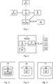
- Fig 1 is a schematic diagram illustrating a system where embodiments presented herein can be applied.
- An electronically controlled physical lock 8 is controlled by a local control unit 7.
- the electronically controlled physical lock 8 can also be controlled by a conventional mechanical key.
- a reader device 1 communicates with an electronic access key 10, in possession of a user, using near field radio frequency communication.
- a user interface device 9 allows the user to input data into and read data from the system.
- the electronically controlled physical lock 8 is controllable by the local control unit 7 to be in a locked or unlocked state, depending on the electronic access key 10. In this way, access to a physical space can be controlled. For example a door can be controlled to be able to be opened when the electronically controlled physical lock 8 is in an unlocked state and not to be able to be opened when the electronically controlled physical lock 8 is in a locked state.
- the local control unit 7 is configured to use additional security measures to gain access, e.g. by requiring a code to be entered using the user interface device 9 or using biometrics.
- a central control unit 5 enables administration of the system and can configure one or more local control units 7.
- the central control unit allows the reader device 1 to receive software upgrades remotely.
- the reader device 1 can subsequently be configured to make use of the software upgrade, e.g. to use a new electronic access key protocol, using an electronic configuration key readable by the reader device 1.
- Each local control unit 7 can e.g. be a computer with a central processing unit, memory, input/output unit(s), etc.
- the communication between the local control unit 7, user interface device 9, reader device 1 and the electronically controlled physical lock 8 can occur using any suitable electronic access key protocol, e.g. using a controller area network (CAN) bus, Ethernet, universal serial bus (USB), serial connections (e.g. RS-232, RS-422, etc.) and/or parallel connections (e.g. Centronics).
- CAN controller area network
- USB universal serial bus
- serial connections e.g. RS-232, RS-422, etc.
- parallel connections e.g. Centronics
- the communication between the local control unit 7 and the central control unit 5 can e.g. occur using a wide area protocol such as Internet Protocol (IP), whereby the local control unit 7 and the central control unit can be situated in remote locations far from each other and can e.g. communicate via the Internet (e.g. using an encrypted connection).
- IP Internet Protocol
- the central control unit 5 can e.g. be a general purpose computer with display, keyboard, etc., with appropriate software installed, allowing an operator to configure one or more connected local control unit, e.g. belonging to one company or installation.
- the local control unit 7, user interface device 9, reader device 1, and electronically controllable physical lock 8 can be e.g. powered by a connection to a mains AC (alternating current) source, optionally via a chargeable backup power storage device such as a rechargeable battery.
- a mains AC (alternating current) source optionally via a chargeable backup power storage device such as a rechargeable battery.
- one or more of the local control unit 7, user interface device 9, reader device 1, and electronically controllable physical lock 8 can be combined in a single physical device.
- Fig 2 is a schematic diagram illustrating a reader device 1 of Fig 1 and its communication with various electronic keys 10-12 according to one embodiment.
- the reader device 1 comprises a controller 4 using any combination of one or more of a suitable central processing unit (CPU), multiprocessor, microcontroller, digital signal processor (DSP), application specific integrated circuit (ASIC), field programmable gate array (FPGA) etc., capable of execution inherent to the controller 4 and/or according to software instructions stored in a computer program product 6.
- the computer program product 6 is memory being any combination of read and write memory (RAM) and read only memory (ROM).
- the memory comprises persistent storage, which, for example, can be any single one or combination of magnetic memory, optical memory, solid state memory or even remotely mounted memory.
- the controller 4 can be configured to execute the method described with reference to Fig 9 below.
- the reader device 1 also comprises a near field radio frequency communication device 3 arranged to communicate with one or more of electronic keys 10-12 using near field communication.
- Near field is here to interpreted as a distance between the reader and the electronic key where electric and magnetic components produced directly by currents and charge-separations dominate.
- the reader device 1 supports a plurality of electronic access key protocols. However, as explained in more detail below, one or more electronic access key protocols can be inactivated using an electronic configuration key 11.
- the near field radio frequency communication device 3 comprises appropriate transmitter and receiver circuitry to read data from a nearby electronic key 10-12.
- the near field radio frequency communication device 3 can comprise circuitry to send a signal to the electronic key 10-12 which energises the electronic key such that data stored on the electronic key is sent to and received by the near field radio frequency communication device 3.
- the reader device 1 can communicate with an electronic access key 10, an electronic configuration key 11 and/or an electronic reset key.
- the electronic access key 10 is read by the reader device 1, and evaluated by the local control unit 7 to allow or deny access.
- the local control unit 7 is thus arranged to determine, based on access data read from the electronic access key 10, whether the electronic access key 10 is eligible to open the electronically controlled physical lock 8.
- the near field radio frequency communication device 3 is arranged to read configuration data from an electronic configuration key 11.
- the controller 4 is arranged to inactivate electronic access key protocol in the reader device based on the configuration data 20. Moreover, installation specific configuration can be applied. This is explained in more detail with reference to Fig 6 below.
- the near field radio frequency communication device 3 is further arranged to read reset data from an electronic reset key 12. Based on the reset data, the controller 4 is arranged to conditionally reset the reader device, to thereby enable all of the supported plurality of electronic access key protocols in the reader device. Also, the reset can optionally remove any installation specific configuration to thereby reset the reader device to a generic state.
- the reader device 1 can support any combination of the following protocols using 13.56 MHz centre frequency (in effect 13.553 MHZ to 13.567 MHZ): MIFARE Classic, MIFARE Ultralight, MIFARE Ultralight EVi, MIFARE Ultralight C, MIFARE DESFire, MIFARE DESFire EV1, MIFARE Plus, MIFARE sam av2, and Near Field Communication (NFC).
- MIFARE Classic MIFARE Ultralight
- MIFARE Ultralight EVi MIFARE Ultralight C
- MIFARE DESFire MIFARE DESFire EV1
- MIFARE Plus MIFARE sam av2
- NFC Near Field Communication
- Fig 3 is a schematic diagram illustrating an electronic configuration key 11 of Fig 2 according to one embodiment.
- the electronic configuration key 11 comprises a memory 15 holding configuration data 20 which, when read by a reader device in a configuration period, makes the reader device 1 inactivate one or more electronic access key protocols.
- the configuration data 20 can control how the electronic access key protocol is to function, e.g. which sectors to read on the electronic access key, etc.
- the configuration data 20 comprises a communication control command section 21 and a communication control parameter section 22.
- the electronic configuration key 11 can use any protocol supported by the reader device 1.
- the electronic configuration key 11 supports one of the electronic access key protocol used by the reader device.
- Fig 4 is a schematic diagram illustrating an unclaimed embodiment of an electronic reset key 12 of Fig 2 .
- the electronic reset key 12 comprises a memory 15' holding reset data 25 which, when read by a reader device in a configuration period, makes the reader device 1 inactivate one or more electronic access key protocols. Since the electronic reset key 12 is used to reset the reader device, it supports an electronic access key protocol which an, already configured reader device, is configured to support.
- Fig 5 is a schematic diagram illustrating an electronic access key 10 of Fig 2 according to one embodiment.
- the electronic access key 10 comprises a memory 15" holding access data 26 which, when read by a reader device in a configuration period, allows the reader device to determine whether to grant or deny access.
- the electronic access key 10 supports an electronic access key protocol which is supported by the reader device 1.
- Fig 6 is a schematic graph illustrating operation of the reader device 1 of Figs 1 and 2 according to one embodiment.
- the reader device is powered up.
- the reader device is arranged to read any electronic configuration key 11 provided within range of the near field radio frequency communication device 3.
- the configuration period ends at time ti, which is a configuration duration after the power on time to.
- the configuration duration represents an amount of time (e.g. a certain number of seconds) and is a parameter which is stored in the reader device.
- the reader device 1 is in a normal operation period 31 and grants or denies access using the electronically controlled physical lock in dependence on what electronica access keys are provided in the vicinity of its near field radio frequency communication device 3.
- the reader device is also only responsive to electronic reset keys in the configuration period 30, and not during the normal operation period 31.
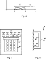
- Fig 7 is a schematic diagram illustrating a user interface device of the user interface device 9 of Fig 2 according to one embodiment.
- the user interface device 9 comprises a plurality of operation indicators 35a-e, an optional display 37 and an alphanumeric keypad 36.
- the operation indicators 35a-e can for instance indicate when access is allowed, access is denied, or that a code sequence needs to be entered on the keypad.
- the operation indicators 35a-e can be provided using different coloured lights and/or different symbols.
- operation indicators using green and red are provided at either end of the set of operation indicators.
- the first operation indicator 35a can be red and the last operation indicator 35e can be green, or vice versa.
- a green operation indicator can indicate that an intrusion detection system is disarmed and a red operation indicator can indicate that an intrusion detection system is armed.
- Fig 7 illustrates five operation indicators 35a-e, any suitable number of operation indicators can be provided.
- the display 37 is used to convey configurable information to the user.
- the display 37 is used to, upon granted access, display until how long the electronic access key is valid, e.g. en end validity date.
- the reader device 1 is integrated with the user interface device 9.
- Fig 8 is a schematic side view of the user interface device 9 of Figs 1 and 7 according to one embodiment. It is here shown how a cable 45 connects the user interface device 9 with other components of the system (see Fig 1 ).
- the cable 45 is guided by a frame 41. In the space behind the frame 41, any excess cable can be stored. In this way, installation of an outer shell 40 can be done after the cable 45 is provided in a suitable way, which simplifies installation of the user interface device.
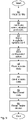
- Fig 9 is a flow chart illustrating one embodiment of a method performed in the reader device of Fig 1 and 2 .
- a read config step 50 configuration data is read from an electronic configuration key.
- an inactivate electronic access key protocol step 52 one or more electronic access key protocols in the reader device are inactivated based on the configuration data.
- an installation specific installation is applied for at least one electronic access key protocol, based on the configuration data. This can be used to improve and customise the security from the generic configuration.
- a configuration period (see 30 of Fig 6 ) is ended at a time which is a configuration duration after when the reader device 1 is powered up. In this way, the inactivate electronic access key protocol step 52 is only performed during the configuration period.
- a read access data step 54 access data is read from an electronic access key. This step can be performed a significant amount of time after the previous steps.
- a send access data step 56 the reader device sends the access data, e.g. to the local control unit.
- the local control unit can determine, based on the access data read from the electronic access key, whether the electronic access key is eligible to gain access to the electronically controlled physical lock.
- the electronically controlled physical lock is set in the unlocked state. Otherwise, the electronically controlled physical lock is set (or remains) in the locked state.
- the method can repeat the read access data step 54 and send access data step 56 as necessary, in a normal operation mode of the reader device.
- reset data is read from an electronic reset key.
- a reset reader device step 60 the reader device is conditionally reset based on the reset data, i.e. when the reset data is considered to be valid reset data. In this way, all of the supported plurality of electronic access key protocols are enabled in the reader device to allow reconfiguration of the reader device.
Landscapes
- Physics & Mathematics (AREA)
- General Physics & Mathematics (AREA)
- Engineering & Computer Science (AREA)
- Computer Networks & Wireless Communication (AREA)
- Lock And Its Accessories (AREA)
Claims (8)
- Leservorrichtung (1), die angeordnet ist, Zugriffsrechte für einen elektronischen Zugriffsschlüssel (10) zu lesen, um Zugriff zu erhalten, um ein elektronisch gesteuertes physisches Schloss (8) zu öffnen, wobei die Leservorrichtung (1) eine Vielzahl von elektronischen Zugriffsschlüsselprotokollen zum Eintreten in eine Kommunikation mit einem elektronischen Zugriffsschlüssel unterstützt und die Leservorrichtung (1) Folgendes umfasst:eine Nahfeldfunkfrequenzkommunikationsvorrichtung (3), die angeordnet ist, Auslegungsdaten (20) aus einem elektronischen Auslegungsschlüssel (11) zu lesen;eine Steuerung (4), die angeordnet ist, mindestens ein elektronisches Zugriffsschlüsselprotokoll in der Leservorrichtung auf Basis der Auslegungsdaten (20) zu deaktivieren;wobei die Nahfeldfunkfrequenzkommunikationsvorrichtung (3) ferner angeordnet ist, Zugriffsdaten (26) aus einem elektronischen Zugriffsschlüssel (10) zu lesen; und die Leservorrichtung angeordnet ist, die Zugriffsdaten (26) zum Bestimmen, ob der elektronische Zugriffsschlüssel (10) zum Öffnen des elektronisch gesteuerten physischen Schlosses (8) qualifiziert ist, an eine Steuereinheit zu senden, wobei die Nahfeldfunkfrequenzkommunikationsvorrichtung (3) ferner angeordnet ist, Rücksetzdaten aus einem elektronischen Rücksetzschlüssel (12) zu lesen; unddie Steuerung (4) ist angeordnet, die Leservorrichtung auf Basis der Rücksetzdaten zurückzusetzen, um dadurch alle der unterstützten Vielzahl von elektronischen Zugriffsschlüsselprotokollen in der Leservorrichtung zu aktivieren;wobei die Leservorrichtung (1) nur während einer Auslegungsperiode auf Auslegungsdaten und Rücksetzdaten reagiert, wobei die Auslegungsperiode beginnt, wenn die Leservorrichtung eingeschaltet wird, und die Auslegungsperiode eine Auslegungsdauer beendet, nachdem die Leservorrichtung (1) eingeschaltet wurde, wobei die Auslegungsdauer eine Zeitmenge repräsentiert und die Auslegungsdauer ein Parameter ist, der in der Leservorrichtung gespeichert ist.
- Leservorrichtung (1) nach Anspruch 1, wobei die Auslegungsdaten (20) einen Kommunikationssteuerbefehlsbereich (21) und einen Kommunikationssteuerparameterbereich (22) umfassen.
- Leservorrichtung (1) nach einem der vorhergehenden Ansprüche, wobei die Steuerung (4) ferner angeordnet ist, eine installationsspezifische Auslegung auf Basis der Auslegungsdaten (20) für mindestens ein elektronisches Zugriffsschlüsselprotokoll anzuwenden.
- Leservorrichtung (1) nach einem der vorhergehenden Ansprüche, wobei die Nahfeldfunkfrequenzkommunikationsvorrichtung (3) um eine Mittenfrequenz von 13,56 MHz betreibbar ist.
- Verfahren zum Auslegen einer Leservorrichtung nach Anspruch 1 zum Lesen von Zugriffsrechten eines elektronischen Zugriffsschlüssels (10), um Zugriff zu erhalten, um ein elektronisch gesteuertes physisches Schloss (8) zu öffnen, wobei das Verfahren in einer Leservorrichtung (1) durchgeführt wird, die eine Vielzahl von elektronischen Zugriffsschlüsselprotokollen zum Eintreten in eine Kommunikation mit einem elektronischen Zugriffsschlüssel unterstützt, wobei die Leservorrichtung nur während einer Auslegungsperiode sowohl auf Auslegungsdaten von einem elektronischen Auslegungsschlüssel als auch auf Rücksetzdaten von einem elektronischen Rücksetzschlüssel reagiert, wobei das Verfahren die folgenden Schritte umfasst:Beginnen einer Auslegungsperiode, wenn die Leservorrichtung eingeschaltet wird;Lesen (50) von Auslegungsdaten (20) von einem elektronischen Auslegungsschlüssel (11), wenn ein elektronischer Auslegungsschlüssel bereitgestellt wird;Deaktivieren (52) von mindestens einem elektronischen Zugriffsschlüsselprotokoll in der Leservorrichtung auf Basis der Auslegungsdaten (20), wenn ein elektronischer Auslegungsschlüssel bereitgestellt wird;Lesen (58) von Rücksetzdaten aus einem elektronischen Rücksetzschlüssel (12), wenn ein elektronischer Rücksetzschlüssel bereitgestellt wird; undRücksetzen (60) der Leservorrichtung (1) auf Basis der Rücksetzdaten, um dadurch alle der unterstützten Vielzahl von elektronischen Zugriffsschlüsselprotokollen in der Leservorrichtung zu aktivieren, wenn ein elektronischer Rücksetzschlüssel bereitgestellt wird; undBeenden (53) der Auslegungsperiode zu einer Zeit, bei der es sich um eine Auslegungsdauer handelt, nachdem die Leservorrichtung (1) eingeschaltet wurde; und wobei die Schritte des Deaktivierens (52) und des Rücksetzens (60) nur während der Auslegungsperiode durchgeführt werden, wobei die Auslegungsdauer eine Zeitmenge repräsentiert und die Auslegungsdauer ein Parameter ist, der in der Leservorrichtung gespeichert ist.
- Verfahren nach Anspruch 5, wobei die Auslegungsdaten (20) einen Kommunikationssteuerbefehlsbereich (21) und einen Kommunikationssteuerparameterbereich (22) umfassen.
- Verfahren nach einem der Ansprüche 5 bis 6, das ferner nach dem Schritt des Lesens der Auslegungsdaten den folgenden Schritt umfasst:
Anwenden (51) einer installationsspezifischen Auslegung auf Basis der Auslegungsdaten (20) für mindestens ein elektronisches Zugriffsschlüsselprotokoll. - Verfahren nach einem der Ansprüche 5 bis 7, wobei das Verfahren ferner einen Schritt des Lesens (54) von Zugriffsdaten (26) aus einem elektronischen Zugriffsschlüssel (10) umfasst und
wobei der Schritt des Lesens der Auslegungsdaten (50) und der Schritt des Lesens der Zugriffsdaten (54) das Lesen um eine Mittenfrequenz von 13,56 MHz umfassen.
Applications Claiming Priority (1)
| Application Number | Priority Date | Filing Date | Title |
|---|---|---|---|
| SE1350544A SE539039C2 (sv) | 2013-05-03 | 2013-05-03 | Läsaranordning för en elektronisk åtkomstnyckel för ett lås samt förfarande för att konfigurera en läsaranordning |
Publications (3)
| Publication Number | Publication Date |
|---|---|
| EP2800067A2 EP2800067A2 (de) | 2014-11-05 |
| EP2800067A3 EP2800067A3 (de) | 2018-01-03 |
| EP2800067B1 true EP2800067B1 (de) | 2022-05-04 |
Family
ID=50440580
Family Applications (1)
| Application Number | Title | Priority Date | Filing Date |
|---|---|---|---|
| EP14164004.5A Active EP2800067B1 (de) | 2013-05-03 | 2014-04-09 | Lesevorrichtung und zugehöriges verfahren |
Country Status (2)
| Country | Link |
|---|---|
| EP (1) | EP2800067B1 (de) |
| SE (1) | SE539039C2 (de) |
Families Citing this family (1)
| Publication number | Priority date | Publication date | Assignee | Title |
|---|---|---|---|---|
| EP3182384B2 (de) * | 2015-12-17 | 2020-09-23 | Axis AB | Verbessertes physisches zugangskontrollsystem |
Citations (2)
| Publication number | Priority date | Publication date | Assignee | Title |
|---|---|---|---|---|
| US20120096131A1 (en) * | 2008-09-30 | 2012-04-19 | Honeywell International Inc. | Systems and methods for interacting with access control devices |
| EP2584539A1 (de) * | 2011-10-20 | 2013-04-24 | Marc Gaston Zacher | Verfahren zum Konfigurieren eines elektromechanischen Schlosses |
Family Cites Families (2)
| Publication number | Priority date | Publication date | Assignee | Title |
|---|---|---|---|---|
| US7376839B2 (en) * | 2001-05-04 | 2008-05-20 | Cubic Corporation | Smart card access control system |
| US7706778B2 (en) * | 2005-04-05 | 2010-04-27 | Assa Abloy Ab | System and method for remotely assigning and revoking access credentials using a near field communication equipped mobile phone |
-
2013
- 2013-05-03 SE SE1350544A patent/SE539039C2/sv unknown
-
2014
- 2014-04-09 EP EP14164004.5A patent/EP2800067B1/de active Active
Patent Citations (2)
| Publication number | Priority date | Publication date | Assignee | Title |
|---|---|---|---|---|
| US20120096131A1 (en) * | 2008-09-30 | 2012-04-19 | Honeywell International Inc. | Systems and methods for interacting with access control devices |
| EP2584539A1 (de) * | 2011-10-20 | 2013-04-24 | Marc Gaston Zacher | Verfahren zum Konfigurieren eines elektromechanischen Schlosses |
Also Published As
| Publication number | Publication date |
|---|---|
| SE1350544A1 (sv) | 2014-11-04 |
| EP2800067A3 (de) | 2018-01-03 |
| SE539039C2 (sv) | 2017-03-28 |
| EP2800067A2 (de) | 2014-11-05 |
Similar Documents
| Publication | Publication Date | Title |
|---|---|---|
| CN107667369B (zh) | 配置锁的移动设备的使用 | |
| EP3029906B1 (de) | Authentifizierungssystem und sendeterminal zur authentifizierung des lichtsignals | |
| EP2821970B2 (de) | Kommunikationsvorrichtung zur Zugriffssteuerung, Verfahren, Computerprogramm und Computerprogrammprodukt | |
| US9779569B2 (en) | Method for controlling door lock of home network system | |
| EP3411854B1 (de) | Doppelkartenprogrammierung für zugangskontrollsystem | |
| EP3129569B1 (de) | Vorübergehende paarung einer mobilen vorrichtung mit einer peripheren vorrichtung | |
| EP4038929B1 (de) | Technologien für zutrittskontrollkommunikation | |
| KR101829018B1 (ko) | 디지털 도어락 시스템 | |
| US10290164B2 (en) | Method for controlling door lock of home network system | |
| EP3039657A1 (de) | Eigentümerzugangspunkt zur steuerung der entsperrung eines eingangs | |
| US20170221287A1 (en) | Transient Asset Management Systems and Methods | |
| CN111542027B (zh) | 控制安全设备的方法、系统和物品 | |
| KR101617707B1 (ko) | 자물쇠 시스템의 제어 권한 전송이 가능한 전자키 시스템 | |
| CN111989723A (zh) | 共享系统 | |
| CA3006190C (en) | Electric lock and control method thereof | |
| US9779566B2 (en) | Resource management based on physical authentication and authorization | |
| EP2800067B1 (de) | Lesevorrichtung und zugehöriges verfahren | |
| CN110827449A (zh) | 一种智能门锁控制系统及控制方法 | |
| US10467830B2 (en) | Electronic credential reader | |
| CN113763603B (zh) | 信息处理装置、方法、计算机可读存储介质及便携终端 | |
| CN116092219A (zh) | 诸如无线电子锁的iot设备的空中更新 | |
| US12001910B1 (en) | Initialization of touchless identity card emulator | |
| US11837037B2 (en) | Universal secure mobile device entry upgrade electronics unit for electronic locks and method of use thereof | |
| KR20130126357A (ko) | 도어락 시스템 | |
| CN108198320A (zh) | 智能门锁开锁装置 |
Legal Events
| Date | Code | Title | Description |
|---|---|---|---|
| PUAI | Public reference made under article 153(3) epc to a published international application that has entered the european phase |
Free format text: ORIGINAL CODE: 0009012 |
|
| 17P | Request for examination filed |
Effective date: 20140409 |
|
| AK | Designated contracting states |
Kind code of ref document: A2 Designated state(s): AL AT BE BG CH CY CZ DE DK EE ES FI FR GB GR HR HU IE IS IT LI LT LU LV MC MK MT NL NO PL PT RO RS SE SI SK SM TR |
|
| AX | Request for extension of the european patent |
Extension state: BA ME |
|
| RIN1 | Information on inventor provided before grant (corrected) |
Inventor name: BLOMQVIST, FREDRIK Inventor name: SEVALLIUS, PATRIK Inventor name: BOVIN, PERLA Inventor name: BERGLUND, JENS Inventor name: JOHANSSON KJERSTAD, OVE |
|
| PUAL | Search report despatched |
Free format text: ORIGINAL CODE: 0009013 |
|
| AK | Designated contracting states |
Kind code of ref document: A3 Designated state(s): AL AT BE BG CH CY CZ DE DK EE ES FI FR GB GR HR HU IE IS IT LI LT LU LV MC MK MT NL NO PL PT RO RS SE SI SK SM TR |
|
| AX | Request for extension of the european patent |
Extension state: BA ME |
|
| RIC1 | Information provided on ipc code assigned before grant |
Ipc: G07C 9/00 20060101AFI20171124BHEP |
|
| STAA | Information on the status of an ep patent application or granted ep patent |
Free format text: STATUS: REQUEST FOR EXAMINATION WAS MADE |
|
| R17P | Request for examination filed (corrected) |
Effective date: 20180709 |
|
| RBV | Designated contracting states (corrected) |
Designated state(s): AL AT BE BG CH CY CZ DE DK EE ES FI FR GB GR HR HU IE IS IT LI LT LU LV MC MK MT NL NO PL PT RO RS SE SI SK SM TR |
|
| STAA | Information on the status of an ep patent application or granted ep patent |
Free format text: STATUS: EXAMINATION IS IN PROGRESS |
|
| 17Q | First examination report despatched |
Effective date: 20200525 |
|
| RAP1 | Party data changed (applicant data changed or rights of an application transferred) |
Owner name: ASSA ABLOY OPENING SOLUTIONS SWEDEN AB |
|
| GRAP | Despatch of communication of intention to grant a patent |
Free format text: ORIGINAL CODE: EPIDOSNIGR1 |
|
| STAA | Information on the status of an ep patent application or granted ep patent |
Free format text: STATUS: GRANT OF PATENT IS INTENDED |
|
| INTG | Intention to grant announced |
Effective date: 20211125 |
|
| GRAS | Grant fee paid |
Free format text: ORIGINAL CODE: EPIDOSNIGR3 |
|
| GRAA | (expected) grant |
Free format text: ORIGINAL CODE: 0009210 |
|
| STAA | Information on the status of an ep patent application or granted ep patent |
Free format text: STATUS: THE PATENT HAS BEEN GRANTED |
|
| RIN1 | Information on inventor provided before grant (corrected) |
Inventor name: JOHANSSON KJERSTAD, OVE Inventor name: BLOMQVIST, FREDRIK Inventor name: SEVALLIUS, PATRIK Inventor name: MUNHOZ, PERLA Inventor name: BERGLUND, JENS |
|
| AK | Designated contracting states |
Kind code of ref document: B1 Designated state(s): AL AT BE BG CH CY CZ DE DK EE ES FI FR GB GR HR HU IE IS IT LI LT LU LV MC MK MT NL NO PL PT RO RS SE SI SK SM TR |
|
| REG | Reference to a national code |
Ref country code: GB Ref legal event code: FG4D |
|
| REG | Reference to a national code |
Ref country code: CH Ref legal event code: EP |
|
| REG | Reference to a national code |
Ref country code: AT Ref legal event code: REF Ref document number: 1489930 Country of ref document: AT Kind code of ref document: T Effective date: 20220515 |
|
| REG | Reference to a national code |
Ref country code: DE Ref legal event code: R096 Ref document number: 602014083507 Country of ref document: DE |
|
| REG | Reference to a national code |
Ref country code: IE Ref legal event code: FG4D |
|
| REG | Reference to a national code |
Ref country code: LT Ref legal event code: MG9D |
|
| REG | Reference to a national code |
Ref country code: NL Ref legal event code: MP Effective date: 20220504 |
|
| REG | Reference to a national code |
Ref country code: AT Ref legal event code: MK05 Ref document number: 1489930 Country of ref document: AT Kind code of ref document: T Effective date: 20220504 |
|
| PG25 | Lapsed in a contracting state [announced via postgrant information from national office to epo] |
Ref country code: SE Free format text: LAPSE BECAUSE OF FAILURE TO SUBMIT A TRANSLATION OF THE DESCRIPTION OR TO PAY THE FEE WITHIN THE PRESCRIBED TIME-LIMIT Effective date: 20220504 Ref country code: PT Free format text: LAPSE BECAUSE OF FAILURE TO SUBMIT A TRANSLATION OF THE DESCRIPTION OR TO PAY THE FEE WITHIN THE PRESCRIBED TIME-LIMIT Effective date: 20220905 Ref country code: NO Free format text: LAPSE BECAUSE OF FAILURE TO SUBMIT A TRANSLATION OF THE DESCRIPTION OR TO PAY THE FEE WITHIN THE PRESCRIBED TIME-LIMIT Effective date: 20220804 Ref country code: NL Free format text: LAPSE BECAUSE OF FAILURE TO SUBMIT A TRANSLATION OF THE DESCRIPTION OR TO PAY THE FEE WITHIN THE PRESCRIBED TIME-LIMIT Effective date: 20220504 Ref country code: LT Free format text: LAPSE BECAUSE OF FAILURE TO SUBMIT A TRANSLATION OF THE DESCRIPTION OR TO PAY THE FEE WITHIN THE PRESCRIBED TIME-LIMIT Effective date: 20220504 Ref country code: HR Free format text: LAPSE BECAUSE OF FAILURE TO SUBMIT A TRANSLATION OF THE DESCRIPTION OR TO PAY THE FEE WITHIN THE PRESCRIBED TIME-LIMIT Effective date: 20220504 Ref country code: GR Free format text: LAPSE BECAUSE OF FAILURE TO SUBMIT A TRANSLATION OF THE DESCRIPTION OR TO PAY THE FEE WITHIN THE PRESCRIBED TIME-LIMIT Effective date: 20220805 Ref country code: FI Free format text: LAPSE BECAUSE OF FAILURE TO SUBMIT A TRANSLATION OF THE DESCRIPTION OR TO PAY THE FEE WITHIN THE PRESCRIBED TIME-LIMIT Effective date: 20220504 Ref country code: ES Free format text: LAPSE BECAUSE OF FAILURE TO SUBMIT A TRANSLATION OF THE DESCRIPTION OR TO PAY THE FEE WITHIN THE PRESCRIBED TIME-LIMIT Effective date: 20220504 Ref country code: BG Free format text: LAPSE BECAUSE OF FAILURE TO SUBMIT A TRANSLATION OF THE DESCRIPTION OR TO PAY THE FEE WITHIN THE PRESCRIBED TIME-LIMIT Effective date: 20220804 Ref country code: AT Free format text: LAPSE BECAUSE OF FAILURE TO SUBMIT A TRANSLATION OF THE DESCRIPTION OR TO PAY THE FEE WITHIN THE PRESCRIBED TIME-LIMIT Effective date: 20220504 |
|
| PG25 | Lapsed in a contracting state [announced via postgrant information from national office to epo] |
Ref country code: RS Free format text: LAPSE BECAUSE OF FAILURE TO SUBMIT A TRANSLATION OF THE DESCRIPTION OR TO PAY THE FEE WITHIN THE PRESCRIBED TIME-LIMIT Effective date: 20220504 Ref country code: PL Free format text: LAPSE BECAUSE OF FAILURE TO SUBMIT A TRANSLATION OF THE DESCRIPTION OR TO PAY THE FEE WITHIN THE PRESCRIBED TIME-LIMIT Effective date: 20220504 Ref country code: LV Free format text: LAPSE BECAUSE OF FAILURE TO SUBMIT A TRANSLATION OF THE DESCRIPTION OR TO PAY THE FEE WITHIN THE PRESCRIBED TIME-LIMIT Effective date: 20220504 Ref country code: IS Free format text: LAPSE BECAUSE OF FAILURE TO SUBMIT A TRANSLATION OF THE DESCRIPTION OR TO PAY THE FEE WITHIN THE PRESCRIBED TIME-LIMIT Effective date: 20220904 |
|
| PG25 | Lapsed in a contracting state [announced via postgrant information from national office to epo] |
Ref country code: SM Free format text: LAPSE BECAUSE OF FAILURE TO SUBMIT A TRANSLATION OF THE DESCRIPTION OR TO PAY THE FEE WITHIN THE PRESCRIBED TIME-LIMIT Effective date: 20220504 Ref country code: SK Free format text: LAPSE BECAUSE OF FAILURE TO SUBMIT A TRANSLATION OF THE DESCRIPTION OR TO PAY THE FEE WITHIN THE PRESCRIBED TIME-LIMIT Effective date: 20220504 Ref country code: RO Free format text: LAPSE BECAUSE OF FAILURE TO SUBMIT A TRANSLATION OF THE DESCRIPTION OR TO PAY THE FEE WITHIN THE PRESCRIBED TIME-LIMIT Effective date: 20220504 Ref country code: EE Free format text: LAPSE BECAUSE OF FAILURE TO SUBMIT A TRANSLATION OF THE DESCRIPTION OR TO PAY THE FEE WITHIN THE PRESCRIBED TIME-LIMIT Effective date: 20220504 Ref country code: DK Free format text: LAPSE BECAUSE OF FAILURE TO SUBMIT A TRANSLATION OF THE DESCRIPTION OR TO PAY THE FEE WITHIN THE PRESCRIBED TIME-LIMIT Effective date: 20220504 Ref country code: CZ Free format text: LAPSE BECAUSE OF FAILURE TO SUBMIT A TRANSLATION OF THE DESCRIPTION OR TO PAY THE FEE WITHIN THE PRESCRIBED TIME-LIMIT Effective date: 20220504 |
|
| REG | Reference to a national code |
Ref country code: DE Ref legal event code: R097 Ref document number: 602014083507 Country of ref document: DE |
|
| PLBE | No opposition filed within time limit |
Free format text: ORIGINAL CODE: 0009261 |
|
| STAA | Information on the status of an ep patent application or granted ep patent |
Free format text: STATUS: NO OPPOSITION FILED WITHIN TIME LIMIT |
|
| PG25 | Lapsed in a contracting state [announced via postgrant information from national office to epo] |
Ref country code: AL Free format text: LAPSE BECAUSE OF FAILURE TO SUBMIT A TRANSLATION OF THE DESCRIPTION OR TO PAY THE FEE WITHIN THE PRESCRIBED TIME-LIMIT Effective date: 20220504 |
|
| 26N | No opposition filed |
Effective date: 20230207 |
|
| PG25 | Lapsed in a contracting state [announced via postgrant information from national office to epo] |
Ref country code: SI Free format text: LAPSE BECAUSE OF FAILURE TO SUBMIT A TRANSLATION OF THE DESCRIPTION OR TO PAY THE FEE WITHIN THE PRESCRIBED TIME-LIMIT Effective date: 20220504 |
|
| REG | Reference to a national code |
Ref country code: CH Ref legal event code: PL |
|
| PG25 | Lapsed in a contracting state [announced via postgrant information from national office to epo] |
Ref country code: LU Free format text: LAPSE BECAUSE OF NON-PAYMENT OF DUE FEES Effective date: 20230409 |
|
| REG | Reference to a national code |
Ref country code: BE Ref legal event code: MM Effective date: 20230430 |
|
| PG25 | Lapsed in a contracting state [announced via postgrant information from national office to epo] |
Ref country code: MC Free format text: LAPSE BECAUSE OF FAILURE TO SUBMIT A TRANSLATION OF THE DESCRIPTION OR TO PAY THE FEE WITHIN THE PRESCRIBED TIME-LIMIT Effective date: 20220504 |
|
| PG25 | Lapsed in a contracting state [announced via postgrant information from national office to epo] |
Ref country code: MC Free format text: LAPSE BECAUSE OF FAILURE TO SUBMIT A TRANSLATION OF THE DESCRIPTION OR TO PAY THE FEE WITHIN THE PRESCRIBED TIME-LIMIT Effective date: 20220504 Ref country code: LI Free format text: LAPSE BECAUSE OF NON-PAYMENT OF DUE FEES Effective date: 20230430 Ref country code: IT Free format text: LAPSE BECAUSE OF FAILURE TO SUBMIT A TRANSLATION OF THE DESCRIPTION OR TO PAY THE FEE WITHIN THE PRESCRIBED TIME-LIMIT Effective date: 20220504 Ref country code: CH Free format text: LAPSE BECAUSE OF NON-PAYMENT OF DUE FEES Effective date: 20230430 |
|
| REG | Reference to a national code |
Ref country code: IE Ref legal event code: MM4A |
|
| PG25 | Lapsed in a contracting state [announced via postgrant information from national office to epo] |
Ref country code: BE Free format text: LAPSE BECAUSE OF NON-PAYMENT OF DUE FEES Effective date: 20230430 |
|
| PG25 | Lapsed in a contracting state [announced via postgrant information from national office to epo] |
Ref country code: IE Free format text: LAPSE BECAUSE OF NON-PAYMENT OF DUE FEES Effective date: 20230409 |
|
| PG25 | Lapsed in a contracting state [announced via postgrant information from national office to epo] |
Ref country code: IE Free format text: LAPSE BECAUSE OF NON-PAYMENT OF DUE FEES Effective date: 20230409 |
|
| PG25 | Lapsed in a contracting state [announced via postgrant information from national office to epo] |
Ref country code: BG Free format text: LAPSE BECAUSE OF FAILURE TO SUBMIT A TRANSLATION OF THE DESCRIPTION OR TO PAY THE FEE WITHIN THE PRESCRIBED TIME-LIMIT Effective date: 20220504 |
|
| PG25 | Lapsed in a contracting state [announced via postgrant information from national office to epo] |
Ref country code: BG Free format text: LAPSE BECAUSE OF FAILURE TO SUBMIT A TRANSLATION OF THE DESCRIPTION OR TO PAY THE FEE WITHIN THE PRESCRIBED TIME-LIMIT Effective date: 20220504 |
|
| PGFP | Annual fee paid to national office [announced via postgrant information from national office to epo] |
Ref country code: FR Payment date: 20250321 Year of fee payment: 12 |
|
| PGFP | Annual fee paid to national office [announced via postgrant information from national office to epo] |
Ref country code: GB Payment date: 20250313 Year of fee payment: 12 |
|
| PGFP | Annual fee paid to national office [announced via postgrant information from national office to epo] |
Ref country code: DE Payment date: 20250311 Year of fee payment: 12 |
|
| PG25 | Lapsed in a contracting state [announced via postgrant information from national office to epo] |
Ref country code: CY Free format text: LAPSE BECAUSE OF FAILURE TO SUBMIT A TRANSLATION OF THE DESCRIPTION OR TO PAY THE FEE WITHIN THE PRESCRIBED TIME-LIMIT; INVALID AB INITIO Effective date: 20140409 |
|
| PG25 | Lapsed in a contracting state [announced via postgrant information from national office to epo] |
Ref country code: HU Free format text: LAPSE BECAUSE OF FAILURE TO SUBMIT A TRANSLATION OF THE DESCRIPTION OR TO PAY THE FEE WITHIN THE PRESCRIBED TIME-LIMIT; INVALID AB INITIO Effective date: 20140409 |
|
| PG25 | Lapsed in a contracting state [announced via postgrant information from national office to epo] |
Ref country code: TR Free format text: LAPSE BECAUSE OF FAILURE TO SUBMIT A TRANSLATION OF THE DESCRIPTION OR TO PAY THE FEE WITHIN THE PRESCRIBED TIME-LIMIT Effective date: 20220504 |