EP2799925A1 - Beleuchtungsvorrichtung sowie Verfahren zum Steuern der Beleuchtungsvorrichtung - Google Patents
Beleuchtungsvorrichtung sowie Verfahren zum Steuern der Beleuchtungsvorrichtung Download PDFInfo
- Publication number
- EP2799925A1 EP2799925A1 EP14001250.1A EP14001250A EP2799925A1 EP 2799925 A1 EP2799925 A1 EP 2799925A1 EP 14001250 A EP14001250 A EP 14001250A EP 2799925 A1 EP2799925 A1 EP 2799925A1
- Authority
- EP
- European Patent Office
- Prior art keywords
- modulator
- beam path
- lighting device
- light source
- light
- Prior art date
- Legal status (The legal status is an assumption and is not a legal conclusion. Google has not performed a legal analysis and makes no representation as to the accuracy of the status listed.)
- Granted
Links
Images

Classifications
-
- G—PHYSICS
- G02—OPTICS
- G02F—OPTICAL DEVICES OR ARRANGEMENTS FOR THE CONTROL OF LIGHT BY MODIFICATION OF THE OPTICAL PROPERTIES OF THE MEDIA OF THE ELEMENTS INVOLVED THEREIN; NON-LINEAR OPTICS; FREQUENCY-CHANGING OF LIGHT; OPTICAL LOGIC ELEMENTS; OPTICAL ANALOGUE/DIGITAL CONVERTERS
- G02F1/00—Devices or arrangements for the control of the intensity, colour, phase, polarisation or direction of light arriving from an independent light source, e.g. switching, gating or modulating; Non-linear optics
- G02F1/29—Devices or arrangements for the control of the intensity, colour, phase, polarisation or direction of light arriving from an independent light source, e.g. switching, gating or modulating; Non-linear optics for the control of the position or the direction of light beams, i.e. deflection
- G02F1/33—Acousto-optical deflection devices
-
- G—PHYSICS
- G01—MEASURING; TESTING
- G01S—RADIO DIRECTION-FINDING; RADIO NAVIGATION; DETERMINING DISTANCE OR VELOCITY BY USE OF RADIO WAVES; LOCATING OR PRESENCE-DETECTING BY USE OF THE REFLECTION OR RERADIATION OF RADIO WAVES; ANALOGOUS ARRANGEMENTS USING OTHER WAVES
- G01S7/00—Details of systems according to groups G01S13/00, G01S15/00, G01S17/00
- G01S7/48—Details of systems according to groups G01S13/00, G01S15/00, G01S17/00 of systems according to group G01S17/00
- G01S7/481—Constructional features, e.g. arrangements of optical elements
- G01S7/4814—Constructional features, e.g. arrangements of optical elements of transmitters alone
-
- G—PHYSICS
- G02—OPTICS
- G02B—OPTICAL ELEMENTS, SYSTEMS OR APPARATUS
- G02B27/00—Optical systems or apparatus not provided for by any of the groups G02B1/00 - G02B26/00, G02B30/00
- G02B27/48—Laser speckle optics
-
- G—PHYSICS
- G01—MEASURING; TESTING
- G01S—RADIO DIRECTION-FINDING; RADIO NAVIGATION; DETERMINING DISTANCE OR VELOCITY BY USE OF RADIO WAVES; LOCATING OR PRESENCE-DETECTING BY USE OF THE REFLECTION OR RERADIATION OF RADIO WAVES; ANALOGOUS ARRANGEMENTS USING OTHER WAVES
- G01S17/00—Systems using the reflection or reradiation of electromagnetic waves other than radio waves, e.g. lidar systems
- G01S17/02—Systems using the reflection of electromagnetic waves other than radio waves
- G01S17/06—Systems determining position data of a target
- G01S17/08—Systems determining position data of a target for measuring distance only
- G01S17/10—Systems determining position data of a target for measuring distance only using transmission of interrupted, pulse-modulated waves
- G01S17/18—Systems determining position data of a target for measuring distance only using transmission of interrupted, pulse-modulated waves wherein range gates are used
-
- G—PHYSICS
- G01—MEASURING; TESTING
- G01S—RADIO DIRECTION-FINDING; RADIO NAVIGATION; DETERMINING DISTANCE OR VELOCITY BY USE OF RADIO WAVES; LOCATING OR PRESENCE-DETECTING BY USE OF THE REFLECTION OR RERADIATION OF RADIO WAVES; ANALOGOUS ARRANGEMENTS USING OTHER WAVES
- G01S17/00—Systems using the reflection or reradiation of electromagnetic waves other than radio waves, e.g. lidar systems
- G01S17/88—Lidar systems specially adapted for specific applications
- G01S17/89—Lidar systems specially adapted for specific applications for mapping or imaging
Definitions
- the present invention relates to a lighting device and a method for illuminating a target with this lighting device.
- active laser target illumination devices and laser target illumination methods are known from the prior art, in which a target object is illuminated by means of laser radiation.
- the range gating method is known in which pulsed laser radiation is used to illuminate a target surface, so that suitable cameras can detect the reflected radiation of this illumination. By pulsing the laser radiation, it is possible to determine a distance to the target surface.
- prior art laser targeting is used in active optical path stretching processes of fast moving targets.
- interference-related disturbances may occur, which are also called speckle effects.
- speckle effects are caused by strong local intensity fluctuations of the reflected light, whereby the image quality is greatly reduced.
- image quality is greatly reduced.
- such a reduced image quality makes subsequent electronic evaluation more difficult, which in particular often makes an optical tracking method impossible.
- the object is achieved by a lighting device which is particularly suitable for illuminating a target to be combated.
- the lighting device according to the invention comprises a light source, which is preferably a laser light source.
- the light source is adapted to emit light along a beam path.
- a first modulator is further introduced, wherein the modulator is arranged to manipulate a direction of the beam path in a first plane. Therefore, it is preferably provided that the modulator can deflect the light radiation emitted by the light source by a predefined angle.
- the first modulator is an active optical element.
- a phase plate is present in the beam path, which has a plurality of optical thicknesses.
- the phase plate is arranged behind the first modulator, so that the light of the light source is first deflected by the modulator before it hits the phase plate.
- the multiplicity of different optical thicknesses of the phase plate can preferably be realized in that the phase plate has an uneven surface.
- a control device is connected to the light source and the first modulator, so that the control device can drive the first modulator with different frequencies. In this way, the beam path can be deflected over a first control period up to a first angle.
- the extent of the first period and the first angle is individually determined by the control device. It is particularly preferred, however, that the first angle is at most 5 millirad, while the control period is in the range of (inclusive) 1 to 10 nanoseconds.
- the light source emits light pulses.
- a light pulse has the duration of the control period, so that the first modulator can be controlled synchronously to the emission of light pulses. In this way, it is advantageously possible to deflect each of the emitted light pulses up to a predetermined angle. Therefore, a wide spread of lighting is possible.
- the light source it is also particularly preferred for the light source to emit a plurality of light pulses during the control period. In any case, it is particularly preferably provided that at least one complete light pulse is emitted during the control period. Thus, it is preferably ensured that each light pulse can be completely deflected by the first modulator.
- the first modulator is an acousto-optical modulator.
- the first modulator is a Bragg cell. Therefore, the first modulator comprises in particular a transparent carrier material through which a, in particular acoustic, wave is passed. The acoustic wave results in different optical densities within the carrier material, so that a diffraction of the beam path can be performed on an optical grating resulting from the different optical densities. In this way, the beam path can be manipulated.
- the first modulator is driven with frequencies which amount to at least 100 MHz.
- the difference of the optical thicknesses and the radiation plate has a value which does not fall below 1 ⁇ m, in particular 5 ⁇ m.
- the value of the difference of the plurality of optical thicknesses of the radiation plate does not exceed 50 ⁇ m, particularly preferably 10 ⁇ m.
- the illumination system comprises a second modulator, which is formed in particular identical to the first modulator.
- the second modulator is preferably set up to manipulate a direction of the beam path in a second plane.
- the second plane is arranged in particular perpendicular to the first plane.
- the illumination device preferably has an optical sensor, which may in particular be a camera.
- the optical sensor is preferably set up to detect the light emitted by the light source and reflected by the target. Since the light source in particular emits light pulses, it is furthermore particularly preferably provided that a determination of a distance of the target from the illumination device is possible by means of the detection of the reflected light pulses by the optical sensor.
- the illumination device according to the invention as described above enables an effective reduction of the speckle effect described above.
- the beam path is guided through various optical thicknesses of the radiation plate. Therefore, as already described, statistically distributed optical path differences arise.
- interactions with atmospheric disturbances or a non-ideal flat target surface can lead to temporally and spatially varying speckle effects.
- By temporally averaging these local and temporal variations it is possible to reduce the influence of the speckle effect on the overall measurement.
- the lighting device according to the invention or according to a preferred embodiment of the invention, an illumination of the target, in which an intensity profile over the beam path is similar to a plateau.
- a Gaussian distribution would occur, with the intensity decreasing towards the edge of the beam path. Therefore, the lighting device according to the invention enables a uniform and thus optimized illumination of the target.
- the invention further relates to a method for illuminating a target, wherein a lighting device with the features described above is used.
- the following steps are carried out in the stated sequence: First, a light pulse is emitted by the light source. Subsequently, the first modulator and / or the second modulator is controlled in such a way that the just emitted light pulse is deflected in a randomly determined direction. Thus, the light pulse passes through a randomly determined area of the phase plate, so that over the cross section of the beam path statistically distributed optical path differences arise.
- the thus manipulated light pulse is preferably directed to the target, so that this can illuminate the target.
- the aforementioned steps are carried out continuously repeated. Therefore, it is particularly preferably provided that the light source continuously emits light pulses, wherein the light pulses are deflected in randomly determined directions.
- the above-described temporal and spatial variation of the phase front distribution over the cross section of the beam path arises at the different emitted light pulses.
- each emitted light pulse is received, which is done in particular by the optical sensor.
- the intensities of the received light pulses are determined, wherein preferably also the phase front distribution over the cross section of the reflected beam path can be determined.
- a time average of the intensity of each pulse is determined.
- an image is generated from the averaged intensity data.
- this figure makes it possible to carry out an optical stretching method with which, for example, a fast moving target can be tracked by an active unit.
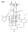
- Fig. 1 shows an illumination device 1, which comprises a light source 10, wherein the light source 10 along a beam path 4 emits pulsed laser beams.
- An optical system 2 is provided to focus the beam path 4 on a target 3 to be illuminated. In this way, a target area 31 can be illuminated by the light source 10.
- the first modulator 7 is set up to deflect the beam path 4, so that the deflected beam path 41 strikes the phase plate 9. From the phase plate 9, the beam path 4 passes through the optical system 2 to the target 3.
- a control device 8 is present and arranged to control the light source 10 and the first modulator 7 in synchronism with each other in time.
- the first modulator 7 is in particular an acousto-optical modulator, which has a base body 70 that is transparent for the beam path 4.
- An acoustic, in particular an ultrasound-based, actuator 71 which can transmit an acoustic wave 73 to an absorber mounted on an opposite side of the main body 70, is attached to one edge of the main body 70.
- the acoustic wave 73 sent between the actuator 71 and the absorber 72 runs perpendicular to the beam path 4.
- the acoustic wave 73 thus generates different optical densities within the main body 70, so that the modulator 7 is able to deflect the beam path 4, since the beam path 4 can be diffracted by the resulting optical grating.
- a first angle 40 up to which the beam path 4 is deflected to the maximum. It is provided that the deflection angle 40 can be determined by the control device 8, wherein the control device 8 further ensures that always a complete light pulse of the light source 10 is deflected.
- control device 8 on the one hand sets the duration of a light pulse to a control period, wherein the same control period is used to transmit the acoustic wave 73 through the main body 70.
- control device 8 transmits several complete light pulses through the light source 10 during the control period.
- the deflected by the first modulator 7 beam path 41 strikes the phase plate 9.
- the phase plate 9 has a plurality of optical thicknesses which vary over a surface 90 of the phase plate 9.
- a detailed view of the phase plate 9 is made Fig. 2 seen.
- Fig. 2 shows the phase plate 9, wherein by way of example a first optical thickness 91, a second optical thickness 92 and a third optical thickness 93 are shown.
- the first optical thickness 91, the second optical thickness 92 and the third optical thickness 93 are created by an irregular surface 90.
- the light must be in Dependence of the position through which it passes through the phase plate 9, cover different lengths optical paths.
- the first modulator 7 force different paths through the phase plate 9 by the deflection of the beam path.
- a temporal and a spatial variation of the phase fronts over the cross section of the deflected beam path 41 arises.
- the thus varied light pulses are finally focused by the optical system 2 on the target 3.
- the light pulses between the optical system 2 and the target 3 can encounter atmospheric disturbances, which can lead to phase shifts of the light pulses.
- a surface 30 of the target 3 may not be ideally flat, so that phase shifts also occur here. Therefore, in the image of a camera 5, which can detect reflected light radiation from the target 3, perturbations in the form of speckle formations occur.
- the speckle effect also occurs temporally and spatially varied. Therefore, by time-averaging the intensities of the received light radiation, the camera 5 can noticeably reduce the effects of the speckle effect.
- Fig. 3 shows a second embodiment of the invention, which represents an additional development of the first embodiment.
- a light source 10 emits light pulses along the beam path 4, wherein the beam path 4 first hits the first modulator 7.
- the first modulator 7 is set up, the beam path 4 in to deflect a first level 100.
- the first level 100 is in Fig. 3 shown as a vertical direction.
- the deflected beam path 41 impinges on a second modulator 75, which in particular is identical to the first modulator 7.
- the second modulator 75 is preferably designed such that it can deflect the deflected beam path 41 in a second plane 200.
- the second level 200 is shown as the horizontal plane.
- first plane 100 and the second plane 200 are arranged perpendicular to each other.
- a greater spatial and temporal variation of the speckle effect is possible, whereby it can be further reduced.
- very high-quality data about the illuminated target 3 are available, so that these data are also suitable in particular for optical tracking methods.
Landscapes
- Physics & Mathematics (AREA)
- General Physics & Mathematics (AREA)
- Nonlinear Science (AREA)
- Optics & Photonics (AREA)
- Engineering & Computer Science (AREA)
- Computer Networks & Wireless Communication (AREA)
- Radar, Positioning & Navigation (AREA)
- Remote Sensing (AREA)
- Non-Portable Lighting Devices Or Systems Thereof (AREA)
- Length Measuring Devices By Optical Means (AREA)
- Optical Radar Systems And Details Thereof (AREA)
Abstract
Description
- Die vorliegende Erfindung betrifft eine Beleuchtungsvorrichtung sowie ein Verfahren zum Beleuchten eines Ziels mit dieser Beleuchtungsvorrichtung.
- Aus dem Stand der Technik sind mehrere aktive Laserzielbeleuchtungsgeräte sowie Laserzielbeleuchtungsverfahren bekannt, bei denen ein Zielobjekt mittels Laserstrahlung beleuchtet wird. Insbesondere ist das Range-Gating-Verfahren bekannt, bei dem gepulste Laserstrahlung verwendet wird, um eine Zieloberfläche zu beleuchten, so dass geeignete Kameras die reflektierte Strahlung dieser Beleuchtung erfassen können. Durch das Pulsen der Laserstrahlung ist es möglich, eine Entfernung zu der Zieloberfläche zu bestimmen. Weiterhin wird die Laserzielbeleuchtung im Stand der Technik bei aktiven optischen Treckingverfahren von schnell bewegten Zielen verwendet.
- Es kann jedoch aufgrund der Kohärenz der bei der Laserzielbeleuchtung üblicherweise verwendeten Laserstrahlung und der Einwirkung der auf dem Strahlengang auftretenden atmosphärischen Turbulenzen sowie der nicht ideal ebenen Oberflächenstruktur des Ziels zu interferenzbedingte Störungen kommen, die auch Speckle-Effekte genannt werden. Diese Speckle-Effekte entstehen durch starke lokale Intensitätsschwankungen des reflektierten Lichts, wobei dadurch die Bildqualität stark verringert wird. Eine solche verringerte Bildqualität erschwert jedoch eine nachfolgende elektronische Auswertung, was insbesondere ein optisches Tracking-Verfahren oftmals unmöglich macht.
- Es ist Aufgabe der vorliegenden Erfindung, eine Beleuchtungsvorrichtung bereitzustellen, die bei einfacher und kostengünstiger Herstellung und Montage und bei zuverlässigem und wartungsarmem Betrieb eine hohe Bildqualität der beleuchteten Objekte ermöglicht. Es ist weiter Aufgabe der Erfindung, ein Verfahren zum Beleuchten eines Ziels anzugeben, das bei einfacher und kostengünstiger Anwendung das Aufnehmen von qualitativ hochwertigen Bildern eines beleuchteten Objekts ermöglicht.
- Gelöst wird die Aufgabe durch die Merkmale der Ansprüche 1 und 8. Die Unteransprüche haben bevorzugte Weiterbildungen der Erfindung zum Inhalt.
- Somit wird die Aufgabe gelöst durch eine Beleuchtungsvorrichtung, die insbesondere zur Beleuchtung eines zu bekämpfenden Ziels geeignet ist. Die erfindungsgemäße Beleuchtungsvorrichtung umfasst eine Lichtquelle, die bevorzugt eine Laserlichtquelle ist. Die Lichtquelle ist eingerichtet, Licht entlang eines Strahlengangs auszusenden. In den Strahlengang ist weiterhin ein erster Modulator eingebracht, wobei der Modulator eingerichtet ist, eine Richtung des Strahlengangs in einer ersten Ebene zu manipulieren. Daher ist bevorzugt vorgesehen, dass der Modulator die von der Lichtquelle ausgehende Lichtstrahlung um einen vordefinierten Winkel auslenken kann. Insbesondere ist vorgesehen, dass der erste Modulator ein aktives optisches Element ist. Zusätzlich ist im Strahlengang eine Phasenplatte vorhanden, die eine Vielzahl von optischen Dicken aufweist. Bevorzugt ist die Phasenplatte hinter dem ersten Modulator angeordnet, so dass das Licht der Lichtquelle zunächst durch den Modulator ablenkbar ist, bevor dieses die Phasenplatte trifft. Die Vielzahl von unterschiedlichen optischen Dicken der Phasenplatte kann bevorzugt dadurch realisiert sein, dass die Phasenplatte eine unebene Oberfläche aufweist. Somit entstehen bevorzugt statistisch verteilt optische Wegeunterschiede des Lichts innerhalb des Strahlengangs. Besonders bevorzugt ist vorgesehen, dass diese optischen Wegeunterschiede im Mittel wenige Bruchteile der Wellenlänge des von der Lichtquelle ausgesandten Lichts betragen. Eine Steuervorrichtung ist mit der Lichtquelle und dem ersten Modulator verbunden, so dass die Steuervorrichtung den ersten Modulator mit unterschiedlichen Frequenzen ansteuern kann. Auf diese Weise ist der Strahlengang über einen ersten Steuerzeitraum bis zu einem ersten Winkel auslenkbar. Das Ausmaß des ersten Zeitraums sowie des ersten Winkels ist dabei von der Steuervorrichtung individuell festlegbar. Besonders bevorzugt ist jedoch vorgesehen, dass der erste Winkel maximal 5 Millirad beträgt, während der Steuerzeitraum im Bereich von (einschließlich) 1 bis 10 Nanosekunden liegt.
- Bevorzugt ist vorgesehen, dass die Lichtquelle Lichtpulse aussendet. Besonders bevorzugt ist vorgesehen, dass ein Lichtpuls die Dauer des Steuerzeitraums aufweist, so dass der erste Modulator synchron zu der Abstrahlung von Lichtpulsen angesteuert werden kann. Auf diese Weise ist es vorteilhaft möglich, jeden der ausgesendeten Lichtpulse bis zu einem vorbestimmten Winkel auszulenken. Daher ist eine breite Streuung der Beleuchtung möglich. Alternativ ist ebenso besonders bevorzugt vorgesehen, dass die Lichtquelle während des Steuerzeitraums mehrere Lichtpulse aussendet. In jedem Fall ist besonders bevorzugt vorgesehen, dass während des Steuerzeitraums zumindest ein vollständiger Lichtpuls ausgesendet wird. Somit ist bevorzugt sichergestellt, dass jeder Lichtpuls vollständig von dem ersten Modulator ausgelenkt werden kann.
- Bevorzugt ist weiterhin vorgesehen, dass der erste Modulator ein akusto-optischer Modulator ist. Besonders bevorzugt ist der erste Modulator eine Bragg-Zelle. Daher umfasst der erste Modulator insbesondere ein durchsichtiges Trägermaterial, durch das eine, insbesondere akustische, Welle geleitet wird. Durch die akustische Welle entstehen unterschiedliche optische Dichten innerhalb des Trägermaterials, so dass eine Beugung des Strahlengangs an einem aus den unterschiedlichen optischen Dichten resultierenden optischen Gitter ausgeführt werden kann. Auf diese Weise ist der Strahlengang manipulierbar. Durch das Ansteuern des ersten Modulators mit verschiedenen Frequenzen, das bedeutet das Aussenden von unterschiedlichen Schallwellen, kann der Grad der Auslenkung verändert werden. Somit ist es bevorzugt möglich, die Manipulation des Strahlengangs sehr variabel zu gestalten. Besonders bevorzugt wird der erste Modulator mit Frequenzen angesteuert, die zumindest 100 MHz betragen.
- Vorteilhafterweise weist die Differenz der optischen Dicken und der Strahlenplatte einen Wert auf, der 1 µm, insbesondere 5 µm, nicht unterschreitet. Alternativ oder zusätzlich ist es bevorzugt vorgesehen, dass der Wert der Differenz der Vielzahl der optischen Dicken der Strahlenplatte 50 µm, besonders bevorzugt 10 µm, nicht überschreitet. Somit kann der von dem ersten Modulator ausgelenkte Strahlengang verschiedene optische Dicken der Strahlenplatte passieren, wobei durch die verschiedenen optischen Dicken statistisch verteilte optische Wegeunterschiede entstehen. Durch die zuvor genannten Werte der Differenzen der optischen Dicken ist dennoch sichergestellt, dass diese Wegeunterschiede im Mittel wenige Bruchteile der Laserwellenlänge betragen, was für eine effektive Zielbeleuchtung optimale Voraussetzungen darstellt.
- In einer vorteilhaften Ausführungsform der Erfindung umfasst das Beleuchtungssystem einen zweiten Modulator, der insbesondere mit dem ersten Modulator identisch ausgebildet ist. Der zweite Modulator ist bevorzugt eingerichtet, eine Richtung des Strahlengangs in einer zweiten Ebene zu manipulieren. Dabei ist die zweite Ebene insbesondere senkrecht zu der ersten Ebene angeordnet. Die Verwendung des zweiten Modulators ermöglicht daher in vorteilhafter Weise, den Strahlengang in sämtliche Raumrichtungen auszulenken. Somit kann die Vielfalt der möglichen Ablenkrichtungen erhöht werden, was eine effektive Variation der Wegunterschiede des Lichts ermöglicht.
- Weiterhin weist die Beleuchtungsvorrichtung bevorzugt einen optischen Sensor auf, der insbesondere eine Kamera sein kann. Der optische Sensor ist bevorzugt eingerichtet, das von der Lichtquelle ausgesandte und von dem Ziel reflektierte Licht zu detektieren. Da die Lichtquelle insbesondere Lichtpulse aussendet, ist weiterhin besonders bevorzugt vorgesehen, dass mittels des Detektierens der reflektierten Lichtpulse durch den optischen Sensor eine Bestimmung einer Entfernung des Ziels zu der Beleuchtungsvorrichtung möglich ist.
- Die erfindungsgemäße Beleuchtungsvorrichtung wie zuvor beschrieben ermöglicht eine effektive Reduzierung des eingangs beschriebenen Speckle-Effekts. Durch die Auslenkung des Strahlengangs mittels des ersten Modulators wird der Strahlengang durch verschiedene optische Dicken der Strahlenplatte geleitet. Daher entstehen, wie bereits beschrieben, statistisch verteilte optische Wegeunterschiede. Auf diese Weise ist es möglich, örtliche und zeitliche Variationen der Phasenfronten der ausgesandten Lichtpulse im Querschnitt des Strahlengangs zu erzeugen. Somit können Wechselwirkungen mit atmosphärischen Störungen oder einer nicht ideal ebenen Zieloberfläche zu zeitlich und örtlich variierenden Speckle-Effekten führen. Durch eine zeitliche Mittelung dieser örtlichen und zeitlichen Variationen ist es möglich, den Einfluss des Speckle-Effekts auf die Gesamtmessung zu reduzieren.
- Weiterhin ermöglicht die Beleuchtungsvorrichtung gemäß der Erfindung oder gemäß einer bevorzugten Weiterbildung der Erfindung, eine Beleuchtung des Ziels, bei der ein Intensitätsverlauf über den Strahlengang einem Plateau ähnelt. Im Gegensatz dazu würde bei herkömmlichen Beleuchtungsvorrichtungen eine Gauß-förmige Verteilung auftreten, wobei die Intensität zum Rand des Strahlengangs hin abnimmt. Daher ermöglicht die erfindungsgemäße Beleuchtungsvorrichtung eine gleichmäßige und damit optimierte Beleuchtung des Ziels.
- Die Erfindung betrifft weiterhin ein Verfahren zum Beleuchten eines Ziels, wobei eine Beleuchtungseinrichtung mit den zuvor beschriebenen Merkmalen verwendet wird. Erfindungsgemäß werden die folgenden Schritte in der angegebenen Reihenfolge ausgeführt: Zunächst wird ein Lichtpuls durch die Lichtquelle ausgesandt. Anschließend wird der erste Modulator und/oder der zweite Modulator derart angesteuert, dass der eben ausgesandte Lichtpuls in eine zufällig bestimmte Richtung ausgelenkt wird. Somit verläuft der Lichtpuls durch einen zufällig bestimmten Bereich der Phasenplatte, so dass über den Querschnitt des Strahlengangs statistisch verteilte optische Wegeunterschiede entstehen. Der so manipulierte Lichtpuls wird bevorzugt auf das Ziel gerichtet, damit dieser dass Ziel beleuchten kann.
- In einer bevorzugten Ausführungsform werden die zuvor genannten Schritte kontinuierlich wiederholend ausgeführt. Daher ist besonders bevorzugt vorgesehen, dass die Lichtquelle kontinuierlich Lichtpulse aussendet, wobei die Lichtpulse in zufällig bestimmte Richtungen ausgelenkt werden. Somit entsteht die zuvor beschriebene zeitliche und räumliche Variation der Phasenfrontverteilung über den Querschnitt des Strahlengangs bei den unterschiedlichen ausgesandten Lichtpulsen.
- Weiterhin ist bevorzugt vorgesehen, dass die zusätzlichen folgenden Schritte ausgeführt werden: Zunächst wird jeder ausgesandte Lichtpuls empfangen, was insbesondere durch den optischen Sensor geschieht. Anschließend werden die Intensitäten der empfangenen Lichtpulse bestimmt, wobei bevorzugt auch die Phasenfrontenverteilung über den Querschnitt des reflektierten Strahlengangs bestimmt werden kann. Dabei wird ein zeitlicher Mittelwert der Intensität jedes Pulses bestimmt. Auf diese Weise ist es möglich, den Einfluss von Speckle-Effekten zu reduzieren, da durch das zuvor beschriebene Aussenden der Lichtpulse und Manipulieren der Richtung der ausgesandten Lichtpulse der Speckle-Effekt räumlich und zeitlich variiert wird. Abschließend ist bevorzugt vorgesehen, dass aus den gemittelten Intensitätsdaten eine Abbildung erzeugt wird. Diese Abbildung ermöglicht insbesondere ein Durchführen eines optischen Treckingverfahrens, mit dem beispielsweise ein schnell bewegliches Ziel von einer Wirkeinheit verfolgt werden kann.
- Die Erfindung wird nun anhand von Ausführungsbeispielen unter Bezugnahme auf die begleitenden Zeichnungen genauer beschrieben. In den Zeichnungen ist:
- Fig. 1
- eine schematische Darstellung der Beleuchtungsvorrichtung gemäß einem ersten Ausführungsbeispiel der Erfindung,
- Fig. 2
- eine schematische Darstellung der Strahlenplatte der Beleuchtungsvorrichtung gemäß dem ersten Ausführungsbeispiel der Erfindung, und
- Fig. 3
- eine schematische Darstellung eines Teils der Beleuchtungsvorrichtung gemäß einem zweiten Ausführungsbeispiel der Erfindung.
-
Fig. 1 zeigt eine Beleuchtungsvorrichtung 1, die eine Lichtquelle 10 umfasst, wobei die Lichtquelle 10 entlang eines Strahlengangs 4 gepulste Laserstrahlen aussendet. Ein optisches System 2 ist vorhanden, um den Strahlengang 4 auf ein zu beleuchtendes Ziel 3 zu fokussieren. Auf diese Weise kann ein Zielbereich 31 von der Lichtquelle 10 beleuchtet werden. - Zwischen dem optischen System 2 und der Lichtquelle 10 ist ein erster Modulator sowie eine Phasenplatte 9 angeordnet. Der erste Modulator 7 ist dabei eingerichtet, den Strahlengang 4 auszulenken, so dass der ausgelenkte Strahlengang 41 auf die Phasenplatte 9 trifft. Von der Phasenplatte 9 gelangt der Strahlengang 4 durch das optische System 2 zu dem Ziel 3.
- Eine Steuervorrichtung 8 ist vorhanden und eingerichtet, die Lichtquelle 10 und den ersten Modulator 7 zeitlich synchron zueinander anzusteuern. Dazu ist der erste Modulator 7 insbesondere ein akusto-optischer Modulator, der einen für den Strahlengang 4 durchsichtigen Grundkörper 70 aufweist. An einem Rand des Grundkörpers 70 ist ein akustischer, insbesondere ein Ultraschall-basierter, Aktuator 71 angebracht, der eine akustische Welle 73 zu einem auf einer gegenüberliegenden Seite des Grundkörpers 70 angebrachten Absorber senden kann. Insbesondere ist vorgesehen, dass die zwischen Aktuator 71 und Absorber 72 gesendete akustische Welle 73 senkrecht zu dem Strahlengang 4 verläuft. Die akustische Welle 73 erzeugt somit unterschiedliche optische Dichten innerhalb des Grundkörpers 70, so dass der Modulator 7 in der Lage ist, den Strahlengang 4 auszulenken, da der Strahlengang 4 durch das entstehende optische Gitter gebeugt werden kann. Durch das Festlegen von unterschiedlichen Frequenzen der akustischen Welle 73 ist es möglich, einen ersten Winkel 40 zu bestimmen, bis zu dem der Strahlengang 4 maximal ausgelenkt wird. Dabei ist vorgesehen, dass der Ablenkwinkel 40 von der Steuervorrichtung 8 bestimmt werden kann, wobei die Steuervorrichtung 8 weiterhin dafür sorgt, dass stets ein vollständiger Lichtpuls der Lichtquelle 10 abgelenkt wird. Daher ist bevorzug vorgesehen, dass die Steuervorrichtung 8 einerseits die Dauer eines Lichtpulses auf einen Steuerzeitraum festlegt, wobei derselbe Steuerzeitraum verwendet wird, um die akustische Welle 73 durch den Grundkörper 70 zu senden. Alternativ ist ebenso bevorzugt vorgesehen, dass die Steuervorrichtung 8 während des Steuerzeitraums mehrere vollständige Lichtpulse durch die Lichtquelle 10 aussendet.
- Der von dem ersten Modulator 7 ausgelenkte Strahlengang 41 trifft auf die Phasenplatte 9. Die Phasenplatte 9 weist eine Vielzahl von optischen Dicken auf, die über eine Oberfläche 90 der Phasenplatte 9 variieren. Eine detaillierte Ansicht der Phasenplatte 9 ist aus
Fig. 2 ersichtlich. -
Fig. 2 zeigt die Phasenplatte 9, wobei beispielhaft eine erste optische Dickte 91, eine zweite optische Dicke 92 und eine dritte optische Dicke 93 eingezeichnet sind. Die erste optische Dicke 91, die zweite optische Dicke 92 und die dritte optische Dicke 93 entstehen durch eine unregelmäßige Oberfläche 90. Somit muss das Licht in Abhängigkeit der Position, durch das es die Phasenplatte 9 durchläuft, unterschiedlich lange optische Wege zurücklegen. - Wie aus
Fig. 1 ersichtlich ist, kann der erste Modulator 7 durch die Auslenkung des Strahlengangs 4 unterschiedliche Wege durch die Phasenplatte 9 erzwingen. Somit entsteht eine zeitliche und eine räumliche Variation der Phasenfronten über den Querschnitt des abgelenkten Strahlengangs 41. Die so variierten Lichtpulse werden schließlich durch das optische System 2 auf das Ziel 3 fokussiert. - Es ist jedoch möglich, dass die Lichtpulse zwischen dem optischen System 2 und dem Ziel 3 auf atmosphärische Störungen treffen, die zu Phasenverschiebungen der Lichtpulse führen können. Weiterhin kann eine Oberfläche 30 des Ziels 3 nicht ideal eben sein, so dass auch hier Phasenverschiebungen auftreten. Daher treten in dem Bild einer Kamera 5, die reflektierte Lichtstrahlung von dem Ziel 3 erfassen kann, Störungen in Form von Speckle-Bildungen auf. Da jedoch, wie zuvor beschrieben, die Phasenfrontenverteilung der Lichtpulse über den Querschnitt des Strahlengangs 4 zeitlich und räumlich variiert wird, tritt auch der Speckle-Effekt zeitlich und räumlich variiert auf. Daher kann die Kamera 5 durch eine zeitliche Mittelung der Intensitäten der empfangenen Lichtstrahlung die Auswirkungen des Speckle-Effekts spürbar reduzieren.
- Insbesondere kann jeder Lichtpuls ausgelenkt werden, um einen Winkelbereich zu überstreichen, der sich von dem ausgelenkten Zustand bis zu dem maximal ausgelenkten Zustand bei dem ersten Winkel 40 erstreckt. Besonders bevorzugt kann der Lichtpuls aus der unausgelenkten Lage bis zu dem ersten Winkel 40 ausgelenkt werden, um anschließend wieder in die unausgelenkte Lage zurückgelenkt zu werden. Durch das Überstreichen des beschriebenen Winkelbereichs entsteht eine Vielzahl von Speckle-Effekten, die sich bei zeitlicher Mittelung reduzieren oder auslöschen.
-
Fig. 3 zeigt ein zweites Ausführungsbeispiel der Erfindung, das eine zusätzliche Weiterbildung des ersten Ausführungsbeispiels darstellt. Der Einfachheit halber ist hier lediglich ein Teil der Beleuchtungsvorrichtung 1 gezeigt. Eine Lichtquelle 10 sendet Lichtpulse entlang des Strahlengangs 4 aus, wobei der Strahlengang 4 zunächst den ersten Modulator 7 trifft. Der erste Modulator 7 ist eingerichtet, den Strahlengang 4 in einer ersten Ebene 100 auszulenken. Die erste Ebene 100 ist inFig. 3 als vertikale Richtung dargestellt. Anschließend trifft der ausgelenkte Strahlengang 41 auf einen zweiten Modulator 75, der insbesondere identisch zu dem ersten Modulator 7 ausgebildet ist. Der zweite Modulator 75 ist dabei bevorzugt derart ausgebildet, dass dieser den ausgelenkten Strahlengang 41 in einer zweiten Ebene 200 ablenken kann. InFig. 3 ist die zweite Ebene 200 als die horizontale Ebene dargestellt. Es ist daher ersichtlich, dass die erste Ebene 100 und die zweite Ebene 200 senkrecht zueinander angeordnet sind. Somit ist es möglich, den Strahlengang 4 des von der Lichtquelle 10 ausgesandten Lichts in sämtliche Raumrichtungen auszulenken, indem die Auslenkungen des ersten Modulators 7 und des zweiten Modulators 75 kombiniert werden. Somit ist eine größere räumliche und zeitliche Variation des Speckle-Effekts möglich, wodurch dieser weiter reduziert werden kann. Insgesamt stehen daher sehr hochwertige Daten über das beleuchtete Ziel 3 zur Verfügung, so dass diese Daten insbesondere auch für optische Tracking-Verfahren geeignet sind. -
- 1
- Beleuchtungsvorrichtung
- 2
- Optisches System
- 3
- Ziel
- 30
- Oberfläche des Ziels
- 31
- Beleuchteter Zielbereich
- 4
- Strahlengang
- 40
- Erster Winkel
- 41
- Ausgelenkter Strahlengang
- 5
- Optischer Sensor
- 6
- Atmosphärische Störung
- 7
- Erster Modulator
- 70
- Grundkörper
- 71
- Aktuator
- 72
- Absorber
- 73
- Welle
- 75
- Zweiter Modulator
- 8
- Steuervorrichtung
- 9
- Phasenplatte
- 90
- Oberfläche der Phasenplatte
- 91
- Erste optische Dicke der Phasenplatte
- 92
- Zweite optische Dicke der Phasenplatte
- 93
- Dritte optische Dicke der Phasenplatte
- 10
- Lichtquelle
- 100
- Erste Richtung
- 200
- Zweite Richtung
Claims (10)
- Beleuchtungsvorrichtung (1), insbesondere zur Beleuchtung eines zu bekämpfenden Zieles (3), umfassend- eine Lichtquelle (10), insbesondere eine Laserlichtquelle, zum Aussenden von Licht entlang eines Strahlengangs (4),- einen ersten Modulator (7), der in den Strahlengang (4) eingebracht ist und eingerichtet ist, eine Richtung des Strahlengangs (4) in einer ersten Ebene (100) zu manipulieren,- eine Phasenplatte (9), die in den Strahlengang (4) eingebracht ist und die eine Vielzahl von unterschiedlichen optischen Dicken (91, 92, 93) aufweist, und- eine Steuervorrichtung (8), die mit der Lichtquelle (10) und dem ersten Modulator (7) verbunden ist und die eingerichtet ist, den ersten Modulator (7) mit unterschiedlichen Frequenzen anzusteuern, so dass der Strahlengang (4) über einen Steuerzeitraum bis zu einem ersten Winkel (40) auslenkbar ist.
- Beleuchtungsvorrichtung (1) nach Anspruch 1, dadurch gekennzeichnet, dass die Lichtquelle (10) Lichtpulse aussendet.
- Beleuchtungsvorrichtung (1) nach Anspruch 2, dadurch gekennzeichnet, dass die Lichtquelle (10) während des Steuerzeitraums zumindest einen vollständigen Lichtpuls aussendet.
- Beleuchtungsvorrichtung (1) nach einem der vorhergehenden Ansprüche, dadurch gekennzeichnet, dass der erste Modulator (7) ein akusto-optischer Modulator, insbesondere eine Bragg-Zelle, ist.
- Beleuchtungsvorrichtung (1) nach einem der vorhergehenden Ansprüche, dadurch gekennzeichnet, dass eine Differenz der Vielzahl der optischen Dicken (91, 92, 93) der Strahlenplatte (9) einen Wert von 1 Mikrometer, insbesondere einen Wert von 5 Mikrometern, nicht unterschreitet und/oder einen Wert von 50 Mikrometern, insbesondere einen Wert von 10 Mikrometern, nicht überschreitet.
- Beleuchtungsvorrichtung (1) nach einem der vorhergehenden Ansprüche, gekennzeichnet durch einen zweiten Modulator (75), der insbesondere mit dem ersten Modulator (7) identisch ausgebildet ist, wobei der zweite Modulator (75) eingerichtet ist, eine Richtung des Strahlengangs (4) in einer zweiten Ebene (200) zu manipulieren, wobei die erste Ebene (100) und die zweite Ebene (200) insbesondere senkrecht zueinander verlaufen.
- Beleuchtungsvorrichtung (1) nach einem der vorhergehenden Ansprüche, gekennzeichnet durch einen optischen Sensor (5), insbesondere eine Kamera, der eingerichtet ist, von der Lichtquelle (10) ausgesandete und von dem Ziel (3) reflektierte Lichtstrahlung zu detektieren.
- Verfahren zum Beleuchten eines Ziels (3), mit einer Beleuchtungsvorrichtung (1) nach einer der vorhergehenden Ansprüchen, umfassend die folgenden Schritte, die in der angegebenen Reihenfolge ausgeführt werden:- Aussenden eines Lichtpulses durch die Lichtquelle (10),- Ansteuern des ersten Modulators (7) und/oder des zweiten Modulators (75) zum Auslenken des Lichtpulses in eine zufällig bestimmte Richtung,
- Verfahren nach Anspruch 8, dadurch gekennzeichnet, dass die Schritte kontinuierlich wiederholend ausgeführt werden.
- Verfahren nach Anspruch 9, umfassend die zusätzlichen Schritte:- Empfangen jedes ausgesandten Lichtpulses,- Bestimmen eines zeitlichen Mittelwerts der Intensität des empfangenen Lichtpulses.
Applications Claiming Priority (1)
| Application Number | Priority Date | Filing Date | Title |
|---|---|---|---|
| DE102013006813.4A DE102013006813B4 (de) | 2013-04-19 | 2013-04-19 | Beleuchtungsvorrichtung sowie Verfahren zum Beleuchten eines Ziels mit der Beleuchtungsvorrichtung |
Publications (2)
| Publication Number | Publication Date |
|---|---|
| EP2799925A1 true EP2799925A1 (de) | 2014-11-05 |
| EP2799925B1 EP2799925B1 (de) | 2020-08-19 |
Family
ID=50488966
Family Applications (1)
| Application Number | Title | Priority Date | Filing Date |
|---|---|---|---|
| EP14001250.1A Active EP2799925B1 (de) | 2013-04-19 | 2014-04-04 | Laserzielbeleuchtungsvorrichtung sowie Verfahren zum Steuern der Laserzielbeleuchtungsvorrichtung |
Country Status (5)
| Country | Link |
|---|---|
| US (1) | US10197885B2 (de) |
| EP (1) | EP2799925B1 (de) |
| DE (1) | DE102013006813B4 (de) |
| ES (1) | ES2817829T3 (de) |
| SG (1) | SG10201401449WA (de) |
Families Citing this family (2)
| Publication number | Priority date | Publication date | Assignee | Title |
|---|---|---|---|---|
| AT516743B1 (de) * | 2015-04-16 | 2016-08-15 | Zizala Lichtsysteme Gmbh | Beleuchtungsvorrichtung für ein Kraftfahrzeug |
| DE102021201501A1 (de) | 2021-02-17 | 2022-08-18 | Robert Bosch Gesellschaft mit beschränkter Haftung | Vorrichtung sowie Verfahren zur Vermeidung destruktiver Interferenzen bei einer optischen Detektion |
Citations (4)
| Publication number | Priority date | Publication date | Assignee | Title |
|---|---|---|---|---|
| US20020154375A1 (en) * | 2001-02-20 | 2002-10-24 | Eastman Kodak Company | Speckle suppressed laser projection system using RF injection |
| US20090213350A1 (en) * | 2008-02-22 | 2009-08-27 | Nikon Corporation | Coherence-reduction devices and methods for pulsed lasers |
| JP2011128639A (ja) * | 2011-01-26 | 2011-06-30 | Mitsubishi Electric Corp | スペックル除去光源および照明装置 |
| US20120218615A1 (en) * | 2011-02-24 | 2012-08-30 | Stanley Electric Co., Ltd. | Light scattering element, optical scanning device, and image displaying device |
Family Cites Families (5)
| Publication number | Priority date | Publication date | Assignee | Title |
|---|---|---|---|---|
| US4516853A (en) * | 1982-03-31 | 1985-05-14 | United Technologies Corporation | Laser radar adaptive tracking system |
| GB2393056B (en) * | 1992-10-24 | 2004-09-01 | British Aerospace | Tracking systems |
| WO2007049525A1 (en) * | 2005-10-26 | 2007-05-03 | Semiconductor Energy Laboratory Co., Ltd. | Laser irradiation apparatus and manufacturing method of semiconductor device |
| US8451195B2 (en) * | 2006-02-15 | 2013-05-28 | Prysm, Inc. | Servo-assisted scanning beam display systems using fluorescent screens |
| WO2012100261A1 (en) | 2011-01-21 | 2012-07-26 | Clear Align Llc | System and apparatuses providing laser illumination with reduced or zero speckle |
-
2013
- 2013-04-19 DE DE102013006813.4A patent/DE102013006813B4/de active Active
-
2014
- 2014-04-04 ES ES14001250T patent/ES2817829T3/es active Active
- 2014-04-04 EP EP14001250.1A patent/EP2799925B1/de active Active
- 2014-04-11 SG SG10201401449WA patent/SG10201401449WA/en unknown
- 2014-04-18 US US14/256,237 patent/US10197885B2/en active Active
Patent Citations (4)
| Publication number | Priority date | Publication date | Assignee | Title |
|---|---|---|---|---|
| US20020154375A1 (en) * | 2001-02-20 | 2002-10-24 | Eastman Kodak Company | Speckle suppressed laser projection system using RF injection |
| US20090213350A1 (en) * | 2008-02-22 | 2009-08-27 | Nikon Corporation | Coherence-reduction devices and methods for pulsed lasers |
| JP2011128639A (ja) * | 2011-01-26 | 2011-06-30 | Mitsubishi Electric Corp | スペックル除去光源および照明装置 |
| US20120218615A1 (en) * | 2011-02-24 | 2012-08-30 | Stanley Electric Co., Ltd. | Light scattering element, optical scanning device, and image displaying device |
Non-Patent Citations (2)
| Title |
|---|
| DAVID OXFORD ET AL: "<title>Comparison of speckle reduction techniques on the identification of human activities in laser range-gated SWIR imaging</title>", PROCEEDINGS OF SPIE, vol. 7662, 21 April 2010 (2010-04-21), pages 766206, XP055134802, ISSN: 0277-786X, DOI: 10.1117/12.850735 * |
| RONALD G DRIGGERS ET AL: "Impact of speckle on laser range-gated shortwave infrared imaging system target identification performance", OPTICAL ENGINEERING, 7 March 2003 (2003-03-07), pages 738, XP055134790, Retrieved from the Internet <URL:http://search.proquest.com/docview/233447904> [retrieved on 20140909], DOI: 10.1117/1.1543159 * |
Also Published As
| Publication number | Publication date |
|---|---|
| US20140313569A1 (en) | 2014-10-23 |
| US10197885B2 (en) | 2019-02-05 |
| ES2817829T3 (es) | 2021-04-08 |
| SG10201401449WA (en) | 2014-11-27 |
| DE102013006813B4 (de) | 2021-05-20 |
| EP2799925B1 (de) | 2020-08-19 |
| DE102013006813A1 (de) | 2014-10-23 |
Similar Documents
| Publication | Publication Date | Title |
|---|---|---|
| DE102013004869B4 (de) | Verfahren zur Ausbildung einer Strukturierung an Oberflächen von Bauteilen mit einem Laserstrahl | |
| EP3242107B1 (de) | Optische interferometrische vorrichtung zum erfassen einer 3d-struktur eines objekts | |
| DE102012102363A1 (de) | Verfahren und Vorrichtung zur Bestimmung der Größe eines transparenten Teilchens | |
| EP2470855A1 (de) | Verfahren zur elektronischen ermittlung der schusslage bei einem schiessziel | |
| DE102009047303A1 (de) | Einrichtung für die Kalibrierung eines Sensors | |
| DE102016107052A1 (de) | 3D-Druck-Vorrichtung für die Herstellung eines räumlich ausgedehnten Produkts | |
| DE102017205889B4 (de) | Optische Anordnung und Verfahren zur Laserinterferenzstrukturierung einer Probe | |
| DE102019110157B4 (de) | Fluoreszenz-Rastermikroskop und Verfahren zur Abbildung einer Probe | |
| DE102015010275A1 (de) | Verfahren und Vorrichtung zur lokalen Stabilisierung eines Strahlungsflecks auf einem entfernten Zielobjekt | |
| AT516743A4 (de) | Beleuchtungsvorrichtung für ein Kraftfahrzeug | |
| EP3500872A1 (de) | Optische vorrichtung | |
| DE102017209259A1 (de) | Lidarsystem | |
| DE102018107274B3 (de) | Vorrichtung und Verfahren zur Beaufschlagung eines Fluginsekts mit Tilgungsstrahlung | |
| EP2799925B1 (de) | Laserzielbeleuchtungsvorrichtung sowie Verfahren zum Steuern der Laserzielbeleuchtungsvorrichtung | |
| DE102021111949A1 (de) | Vorrichtung zur scannenden Messung des Abstands zu einem Objekt | |
| DE102008021465A1 (de) | Entfernungsmesssystem | |
| DE202021106329U1 (de) | Optoelektronischer Sensor | |
| DE102017107821A1 (de) | Anordnung mit wenigstens zwei laserdioden und diffraktivem element | |
| EP3349042B1 (de) | Überwachungssensor und flurgebundenes fahrzeug | |
| DE112018000062B4 (de) | Energiestrahl-eingang zu atomsonden-proben aus verschiedenen winkeln | |
| WO2021110297A1 (de) | Vorrichtung zum beleuchten eines werkstücks, verfahren zu dessen modifizierung und verfahren zum vermessen seiner oberfläche | |
| WO2020193275A1 (de) | Laserabstrahlvorrichtung und lidar-basierter umgebungssensor mit einer laserabstrahlvorrichtung | |
| DE102015205400A1 (de) | Verfahren und System zur Untersuchung des Polymerisationsgrads eines aushärtbaren Polymers | |
| DE10345177B3 (de) | Linsensystem zum Homogenisieren von Laserpulsen | |
| DE112007002613T5 (de) | Optisches Gattersystem, das das Moiré-Phänomen nutzt |
Legal Events
| Date | Code | Title | Description |
|---|---|---|---|
| PUAI | Public reference made under article 153(3) epc to a published international application that has entered the european phase |
Free format text: ORIGINAL CODE: 0009012 |
|
| 17P | Request for examination filed |
Effective date: 20140404 |
|
| AK | Designated contracting states |
Kind code of ref document: A1 Designated state(s): AL AT BE BG CH CY CZ DE DK EE ES FI FR GB GR HR HU IE IS IT LI LT LU LV MC MK MT NL NO PL PT RO RS SE SI SK SM TR |
|
| AX | Request for extension of the european patent |
Extension state: BA ME |
|
| R17P | Request for examination filed (corrected) |
Effective date: 20150131 |
|
| STAA | Information on the status of an ep patent application or granted ep patent |
Free format text: STATUS: EXAMINATION IS IN PROGRESS |
|
| 17Q | First examination report despatched |
Effective date: 20180824 |
|
| GRAP | Despatch of communication of intention to grant a patent |
Free format text: ORIGINAL CODE: EPIDOSNIGR1 |
|
| STAA | Information on the status of an ep patent application or granted ep patent |
Free format text: STATUS: GRANT OF PATENT IS INTENDED |
|
| INTG | Intention to grant announced |
Effective date: 20200512 |
|
| GRAS | Grant fee paid |
Free format text: ORIGINAL CODE: EPIDOSNIGR3 |
|
| GRAA | (expected) grant |
Free format text: ORIGINAL CODE: 0009210 |
|
| STAA | Information on the status of an ep patent application or granted ep patent |
Free format text: STATUS: THE PATENT HAS BEEN GRANTED |
|
| AK | Designated contracting states |
Kind code of ref document: B1 Designated state(s): AL AT BE BG CH CY CZ DE DK EE ES FI FR GB GR HR HU IE IS IT LI LT LU LV MC MK MT NL NO PL PT RO RS SE SI SK SM TR |
|
| REG | Reference to a national code |
Ref country code: GB Ref legal event code: FG4D Free format text: NOT ENGLISH |
|
| REG | Reference to a national code |
Ref country code: CH Ref legal event code: EP |
|
| REG | Reference to a national code |
Ref country code: DE Ref legal event code: R096 Ref document number: 502014014633 Country of ref document: DE |
|
| REG | Reference to a national code |
Ref country code: AT Ref legal event code: REF Ref document number: 1304612 Country of ref document: AT Kind code of ref document: T Effective date: 20200915 |
|
| REG | Reference to a national code |
Ref country code: IE Ref legal event code: FG4D Free format text: LANGUAGE OF EP DOCUMENT: GERMAN |
|
| REG | Reference to a national code |
Ref country code: LT Ref legal event code: MG4D |
|
| REG | Reference to a national code |
Ref country code: NL Ref legal event code: MP Effective date: 20200819 |
|
| PG25 | Lapsed in a contracting state [announced via postgrant information from national office to epo] |
Ref country code: FI Free format text: LAPSE BECAUSE OF FAILURE TO SUBMIT A TRANSLATION OF THE DESCRIPTION OR TO PAY THE FEE WITHIN THE PRESCRIBED TIME-LIMIT Effective date: 20200819 Ref country code: NO Free format text: LAPSE BECAUSE OF FAILURE TO SUBMIT A TRANSLATION OF THE DESCRIPTION OR TO PAY THE FEE WITHIN THE PRESCRIBED TIME-LIMIT Effective date: 20201119 Ref country code: PT Free format text: LAPSE BECAUSE OF FAILURE TO SUBMIT A TRANSLATION OF THE DESCRIPTION OR TO PAY THE FEE WITHIN THE PRESCRIBED TIME-LIMIT Effective date: 20201221 Ref country code: HR Free format text: LAPSE BECAUSE OF FAILURE TO SUBMIT A TRANSLATION OF THE DESCRIPTION OR TO PAY THE FEE WITHIN THE PRESCRIBED TIME-LIMIT Effective date: 20200819 Ref country code: BG Free format text: LAPSE BECAUSE OF FAILURE TO SUBMIT A TRANSLATION OF THE DESCRIPTION OR TO PAY THE FEE WITHIN THE PRESCRIBED TIME-LIMIT Effective date: 20201119 Ref country code: SE Free format text: LAPSE BECAUSE OF FAILURE TO SUBMIT A TRANSLATION OF THE DESCRIPTION OR TO PAY THE FEE WITHIN THE PRESCRIBED TIME-LIMIT Effective date: 20200819 Ref country code: GR Free format text: LAPSE BECAUSE OF FAILURE TO SUBMIT A TRANSLATION OF THE DESCRIPTION OR TO PAY THE FEE WITHIN THE PRESCRIBED TIME-LIMIT Effective date: 20201120 Ref country code: LT Free format text: LAPSE BECAUSE OF FAILURE TO SUBMIT A TRANSLATION OF THE DESCRIPTION OR TO PAY THE FEE WITHIN THE PRESCRIBED TIME-LIMIT Effective date: 20200819 |
|
| PG25 | Lapsed in a contracting state [announced via postgrant information from national office to epo] |
Ref country code: PL Free format text: LAPSE BECAUSE OF FAILURE TO SUBMIT A TRANSLATION OF THE DESCRIPTION OR TO PAY THE FEE WITHIN THE PRESCRIBED TIME-LIMIT Effective date: 20200819 Ref country code: LV Free format text: LAPSE BECAUSE OF FAILURE TO SUBMIT A TRANSLATION OF THE DESCRIPTION OR TO PAY THE FEE WITHIN THE PRESCRIBED TIME-LIMIT Effective date: 20200819 Ref country code: NL Free format text: LAPSE BECAUSE OF FAILURE TO SUBMIT A TRANSLATION OF THE DESCRIPTION OR TO PAY THE FEE WITHIN THE PRESCRIBED TIME-LIMIT Effective date: 20200819 Ref country code: RS Free format text: LAPSE BECAUSE OF FAILURE TO SUBMIT A TRANSLATION OF THE DESCRIPTION OR TO PAY THE FEE WITHIN THE PRESCRIBED TIME-LIMIT Effective date: 20200819 Ref country code: IS Free format text: LAPSE BECAUSE OF FAILURE TO SUBMIT A TRANSLATION OF THE DESCRIPTION OR TO PAY THE FEE WITHIN THE PRESCRIBED TIME-LIMIT Effective date: 20201219 |
|
| REG | Reference to a national code |
Ref country code: ES Ref legal event code: FG2A Ref document number: 2817829 Country of ref document: ES Kind code of ref document: T3 Effective date: 20210408 |
|
| PG25 | Lapsed in a contracting state [announced via postgrant information from national office to epo] |
Ref country code: CZ Free format text: LAPSE BECAUSE OF FAILURE TO SUBMIT A TRANSLATION OF THE DESCRIPTION OR TO PAY THE FEE WITHIN THE PRESCRIBED TIME-LIMIT Effective date: 20200819 Ref country code: DK Free format text: LAPSE BECAUSE OF FAILURE TO SUBMIT A TRANSLATION OF THE DESCRIPTION OR TO PAY THE FEE WITHIN THE PRESCRIBED TIME-LIMIT Effective date: 20200819 Ref country code: EE Free format text: LAPSE BECAUSE OF FAILURE TO SUBMIT A TRANSLATION OF THE DESCRIPTION OR TO PAY THE FEE WITHIN THE PRESCRIBED TIME-LIMIT Effective date: 20200819 Ref country code: SM Free format text: LAPSE BECAUSE OF FAILURE TO SUBMIT A TRANSLATION OF THE DESCRIPTION OR TO PAY THE FEE WITHIN THE PRESCRIBED TIME-LIMIT Effective date: 20200819 Ref country code: RO Free format text: LAPSE BECAUSE OF FAILURE TO SUBMIT A TRANSLATION OF THE DESCRIPTION OR TO PAY THE FEE WITHIN THE PRESCRIBED TIME-LIMIT Effective date: 20200819 |
|
| REG | Reference to a national code |
Ref country code: DE Ref legal event code: R097 Ref document number: 502014014633 Country of ref document: DE |
|
| PG25 | Lapsed in a contracting state [announced via postgrant information from national office to epo] |
Ref country code: AL Free format text: LAPSE BECAUSE OF FAILURE TO SUBMIT A TRANSLATION OF THE DESCRIPTION OR TO PAY THE FEE WITHIN THE PRESCRIBED TIME-LIMIT Effective date: 20200819 |
|
| PLBE | No opposition filed within time limit |
Free format text: ORIGINAL CODE: 0009261 |
|
| STAA | Information on the status of an ep patent application or granted ep patent |
Free format text: STATUS: NO OPPOSITION FILED WITHIN TIME LIMIT |
|
| PG25 | Lapsed in a contracting state [announced via postgrant information from national office to epo] |
Ref country code: SK Free format text: LAPSE BECAUSE OF FAILURE TO SUBMIT A TRANSLATION OF THE DESCRIPTION OR TO PAY THE FEE WITHIN THE PRESCRIBED TIME-LIMIT Effective date: 20200819 |
|
| 26N | No opposition filed |
Effective date: 20210520 |
|
| PG25 | Lapsed in a contracting state [announced via postgrant information from national office to epo] |
Ref country code: SI Free format text: LAPSE BECAUSE OF FAILURE TO SUBMIT A TRANSLATION OF THE DESCRIPTION OR TO PAY THE FEE WITHIN THE PRESCRIBED TIME-LIMIT Effective date: 20200819 |
|
| PG25 | Lapsed in a contracting state [announced via postgrant information from national office to epo] |
Ref country code: MC Free format text: LAPSE BECAUSE OF FAILURE TO SUBMIT A TRANSLATION OF THE DESCRIPTION OR TO PAY THE FEE WITHIN THE PRESCRIBED TIME-LIMIT Effective date: 20200819 |
|
| PG25 | Lapsed in a contracting state [announced via postgrant information from national office to epo] |
Ref country code: LU Free format text: LAPSE BECAUSE OF NON-PAYMENT OF DUE FEES Effective date: 20210404 |
|
| REG | Reference to a national code |
Ref country code: BE Ref legal event code: MM Effective date: 20210430 |
|
| PG25 | Lapsed in a contracting state [announced via postgrant information from national office to epo] |
Ref country code: CH Free format text: LAPSE BECAUSE OF NON-PAYMENT OF DUE FEES Effective date: 20210430 Ref country code: LI Free format text: LAPSE BECAUSE OF NON-PAYMENT OF DUE FEES Effective date: 20210430 |
|
| PG25 | Lapsed in a contracting state [announced via postgrant information from national office to epo] |
Ref country code: IE Free format text: LAPSE BECAUSE OF NON-PAYMENT OF DUE FEES Effective date: 20210404 |
|
| PG25 | Lapsed in a contracting state [announced via postgrant information from national office to epo] |
Ref country code: IS Free format text: LAPSE BECAUSE OF FAILURE TO SUBMIT A TRANSLATION OF THE DESCRIPTION OR TO PAY THE FEE WITHIN THE PRESCRIBED TIME-LIMIT Effective date: 20201219 |
|
| REG | Reference to a national code |
Ref country code: AT Ref legal event code: MM01 Ref document number: 1304612 Country of ref document: AT Kind code of ref document: T Effective date: 20210404 |
|
| PG25 | Lapsed in a contracting state [announced via postgrant information from national office to epo] |
Ref country code: BE Free format text: LAPSE BECAUSE OF NON-PAYMENT OF DUE FEES Effective date: 20210430 |
|
| PG25 | Lapsed in a contracting state [announced via postgrant information from national office to epo] |
Ref country code: AT Free format text: LAPSE BECAUSE OF NON-PAYMENT OF DUE FEES Effective date: 20210404 |
|
| PG25 | Lapsed in a contracting state [announced via postgrant information from national office to epo] |
Ref country code: HU Free format text: LAPSE BECAUSE OF FAILURE TO SUBMIT A TRANSLATION OF THE DESCRIPTION OR TO PAY THE FEE WITHIN THE PRESCRIBED TIME-LIMIT; INVALID AB INITIO Effective date: 20140404 |
|
| P01 | Opt-out of the competence of the unified patent court (upc) registered |
Effective date: 20230509 |
|
| PG25 | Lapsed in a contracting state [announced via postgrant information from national office to epo] |
Ref country code: CY Free format text: LAPSE BECAUSE OF FAILURE TO SUBMIT A TRANSLATION OF THE DESCRIPTION OR TO PAY THE FEE WITHIN THE PRESCRIBED TIME-LIMIT Effective date: 20200819 |
|
| PG25 | Lapsed in a contracting state [announced via postgrant information from national office to epo] |
Ref country code: MK Free format text: LAPSE BECAUSE OF FAILURE TO SUBMIT A TRANSLATION OF THE DESCRIPTION OR TO PAY THE FEE WITHIN THE PRESCRIBED TIME-LIMIT Effective date: 20200819 |
|
| PG25 | Lapsed in a contracting state [announced via postgrant information from national office to epo] |
Ref country code: MT Free format text: LAPSE BECAUSE OF FAILURE TO SUBMIT A TRANSLATION OF THE DESCRIPTION OR TO PAY THE FEE WITHIN THE PRESCRIBED TIME-LIMIT Effective date: 20200819 |
|
| PGFP | Annual fee paid to national office [announced via postgrant information from national office to epo] |
Ref country code: DE Payment date: 20250430 Year of fee payment: 12 |
|
| PGFP | Annual fee paid to national office [announced via postgrant information from national office to epo] |
Ref country code: ES Payment date: 20250529 Year of fee payment: 12 Ref country code: GB Payment date: 20250423 Year of fee payment: 12 |
|
| PGFP | Annual fee paid to national office [announced via postgrant information from national office to epo] |
Ref country code: IT Payment date: 20250424 Year of fee payment: 12 |
|
| PGFP | Annual fee paid to national office [announced via postgrant information from national office to epo] |
Ref country code: FR Payment date: 20250425 Year of fee payment: 12 |
|
| PG25 | Lapsed in a contracting state [announced via postgrant information from national office to epo] |
Ref country code: TR Free format text: LAPSE BECAUSE OF FAILURE TO SUBMIT A TRANSLATION OF THE DESCRIPTION OR TO PAY THE FEE WITHIN THE PRESCRIBED TIME-LIMIT Effective date: 20200819 |