EP2799708A1 - Combustion control device for gas engine - Google Patents
Combustion control device for gas engine Download PDFInfo
- Publication number
- EP2799708A1 EP2799708A1 EP12863802.0A EP12863802A EP2799708A1 EP 2799708 A1 EP2799708 A1 EP 2799708A1 EP 12863802 A EP12863802 A EP 12863802A EP 2799708 A1 EP2799708 A1 EP 2799708A1
- Authority
- EP
- European Patent Office
- Prior art keywords
- cylinder
- cylinders
- ignition timing
- calculation part
- knocking
- Prior art date
- Legal status (The legal status is an assumption and is not a legal conclusion. Google has not performed a legal analysis and makes no representation as to the accuracy of the status listed.)
- Granted
Links
- 238000002485 combustion reaction Methods 0.000 title claims description 18
- 230000006835 compression Effects 0.000 claims description 5
- 238000007906 compression Methods 0.000 claims description 5
- 239000007789 gas Substances 0.000 description 30
- 239000000446 fuel Substances 0.000 description 7
- 238000010586 diagram Methods 0.000 description 3
- QVGXLLKOCUKJST-UHFFFAOYSA-N atomic oxygen Chemical compound [O] QVGXLLKOCUKJST-UHFFFAOYSA-N 0.000 description 2
- 238000000034 method Methods 0.000 description 2
- 239000001301 oxygen Substances 0.000 description 2
- 229910052760 oxygen Inorganic materials 0.000 description 2
- 230000000694 effects Effects 0.000 description 1
- 238000002347 injection Methods 0.000 description 1
- 239000007924 injection Substances 0.000 description 1
- 230000007257 malfunction Effects 0.000 description 1
- 239000000463 material Substances 0.000 description 1
- 239000000203 mixture Substances 0.000 description 1
- 230000002265 prevention Effects 0.000 description 1
- 230000000979 retarding effect Effects 0.000 description 1
- 239000000243 solution Substances 0.000 description 1
Images


Classifications
-
- G—PHYSICS
- G01—MEASURING; TESTING
- G01M—TESTING STATIC OR DYNAMIC BALANCE OF MACHINES OR STRUCTURES; TESTING OF STRUCTURES OR APPARATUS, NOT OTHERWISE PROVIDED FOR
- G01M15/00—Testing of engines
- G01M15/04—Testing internal-combustion engines
- G01M15/08—Testing internal-combustion engines by monitoring pressure in cylinders
-
- F—MECHANICAL ENGINEERING; LIGHTING; HEATING; WEAPONS; BLASTING
- F02—COMBUSTION ENGINES; HOT-GAS OR COMBUSTION-PRODUCT ENGINE PLANTS
- F02P—IGNITION, OTHER THAN COMPRESSION IGNITION, FOR INTERNAL-COMBUSTION ENGINES; TESTING OF IGNITION TIMING IN COMPRESSION-IGNITION ENGINES
- F02P5/00—Advancing or retarding ignition; Control therefor
- F02P5/04—Advancing or retarding ignition; Control therefor automatically, as a function of the working conditions of the engine or vehicle or of the atmospheric conditions
- F02P5/145—Advancing or retarding ignition; Control therefor automatically, as a function of the working conditions of the engine or vehicle or of the atmospheric conditions using electrical means
- F02P5/15—Digital data processing
- F02P5/152—Digital data processing dependent on pinking
- F02P5/1525—Digital data processing dependent on pinking with means for compensating the variation of the characteristics of the pinking sensor or of the electrical means, e.g. by ageing
-
- F—MECHANICAL ENGINEERING; LIGHTING; HEATING; WEAPONS; BLASTING
- F02—COMBUSTION ENGINES; HOT-GAS OR COMBUSTION-PRODUCT ENGINE PLANTS
- F02D—CONTROLLING COMBUSTION ENGINES
- F02D19/00—Controlling engines characterised by their use of non-liquid fuels, pluralities of fuels, or non-fuel substances added to the combustible mixtures
- F02D19/02—Controlling engines characterised by their use of non-liquid fuels, pluralities of fuels, or non-fuel substances added to the combustible mixtures peculiar to engines working with gaseous fuels
-
- F—MECHANICAL ENGINEERING; LIGHTING; HEATING; WEAPONS; BLASTING
- F02—COMBUSTION ENGINES; HOT-GAS OR COMBUSTION-PRODUCT ENGINE PLANTS
- F02D—CONTROLLING COMBUSTION ENGINES
- F02D35/00—Controlling engines, dependent on conditions exterior or interior to engines, not otherwise provided for
- F02D35/02—Controlling engines, dependent on conditions exterior or interior to engines, not otherwise provided for on interior conditions
- F02D35/023—Controlling engines, dependent on conditions exterior or interior to engines, not otherwise provided for on interior conditions by determining the cylinder pressure
-
- F—MECHANICAL ENGINEERING; LIGHTING; HEATING; WEAPONS; BLASTING
- F02—COMBUSTION ENGINES; HOT-GAS OR COMBUSTION-PRODUCT ENGINE PLANTS
- F02D—CONTROLLING COMBUSTION ENGINES
- F02D35/00—Controlling engines, dependent on conditions exterior or interior to engines, not otherwise provided for
- F02D35/02—Controlling engines, dependent on conditions exterior or interior to engines, not otherwise provided for on interior conditions
- F02D35/027—Controlling engines, dependent on conditions exterior or interior to engines, not otherwise provided for on interior conditions using knock sensors
-
- F—MECHANICAL ENGINEERING; LIGHTING; HEATING; WEAPONS; BLASTING
- F02—COMBUSTION ENGINES; HOT-GAS OR COMBUSTION-PRODUCT ENGINE PLANTS
- F02D—CONTROLLING COMBUSTION ENGINES
- F02D41/00—Electrical control of supply of combustible mixture or its constituents
- F02D41/0025—Controlling engines characterised by use of non-liquid fuels, pluralities of fuels, or non-fuel substances added to the combustible mixtures
- F02D41/0027—Controlling engines characterised by use of non-liquid fuels, pluralities of fuels, or non-fuel substances added to the combustible mixtures the fuel being gaseous
-
- F—MECHANICAL ENGINEERING; LIGHTING; HEATING; WEAPONS; BLASTING
- F02—COMBUSTION ENGINES; HOT-GAS OR COMBUSTION-PRODUCT ENGINE PLANTS
- F02M—SUPPLYING COMBUSTION ENGINES IN GENERAL WITH COMBUSTIBLE MIXTURES OR CONSTITUENTS THEREOF
- F02M35/00—Combustion-air cleaners, air intakes, intake silencers, or induction systems specially adapted for, or arranged on, internal-combustion engines
- F02M35/10—Air intakes; Induction systems
- F02M35/10373—Sensors for intake systems
- F02M35/1038—Sensors for intake systems for temperature or pressure
-
- F—MECHANICAL ENGINEERING; LIGHTING; HEATING; WEAPONS; BLASTING
- F02—COMBUSTION ENGINES; HOT-GAS OR COMBUSTION-PRODUCT ENGINE PLANTS
- F02P—IGNITION, OTHER THAN COMPRESSION IGNITION, FOR INTERNAL-COMBUSTION ENGINES; TESTING OF IGNITION TIMING IN COMPRESSION-IGNITION ENGINES
- F02P5/00—Advancing or retarding ignition; Control therefor
- F02P5/04—Advancing or retarding ignition; Control therefor automatically, as a function of the working conditions of the engine or vehicle or of the atmospheric conditions
-
- F—MECHANICAL ENGINEERING; LIGHTING; HEATING; WEAPONS; BLASTING
- F02—COMBUSTION ENGINES; HOT-GAS OR COMBUSTION-PRODUCT ENGINE PLANTS
- F02P—IGNITION, OTHER THAN COMPRESSION IGNITION, FOR INTERNAL-COMBUSTION ENGINES; TESTING OF IGNITION TIMING IN COMPRESSION-IGNITION ENGINES
- F02P5/00—Advancing or retarding ignition; Control therefor
- F02P5/04—Advancing or retarding ignition; Control therefor automatically, as a function of the working conditions of the engine or vehicle or of the atmospheric conditions
- F02P5/145—Advancing or retarding ignition; Control therefor automatically, as a function of the working conditions of the engine or vehicle or of the atmospheric conditions using electrical means
- F02P5/15—Digital data processing
- F02P5/152—Digital data processing dependent on pinking
-
- F—MECHANICAL ENGINEERING; LIGHTING; HEATING; WEAPONS; BLASTING
- F02—COMBUSTION ENGINES; HOT-GAS OR COMBUSTION-PRODUCT ENGINE PLANTS
- F02P—IGNITION, OTHER THAN COMPRESSION IGNITION, FOR INTERNAL-COMBUSTION ENGINES; TESTING OF IGNITION TIMING IN COMPRESSION-IGNITION ENGINES
- F02P5/00—Advancing or retarding ignition; Control therefor
- F02P5/04—Advancing or retarding ignition; Control therefor automatically, as a function of the working conditions of the engine or vehicle or of the atmospheric conditions
- F02P5/145—Advancing or retarding ignition; Control therefor automatically, as a function of the working conditions of the engine or vehicle or of the atmospheric conditions using electrical means
- F02P5/15—Digital data processing
- F02P5/153—Digital data processing dependent on combustion pressure
-
- F—MECHANICAL ENGINEERING; LIGHTING; HEATING; WEAPONS; BLASTING
- F02—COMBUSTION ENGINES; HOT-GAS OR COMBUSTION-PRODUCT ENGINE PLANTS
- F02B—INTERNAL-COMBUSTION PISTON ENGINES; COMBUSTION ENGINES IN GENERAL
- F02B29/00—Engines characterised by provision for charging or scavenging not provided for in groups F02B25/00, F02B27/00 or F02B33/00 - F02B39/00; Details thereof
- F02B29/04—Cooling of air intake supply
- F02B29/0406—Layout of the intake air cooling or coolant circuit
-
- Y—GENERAL TAGGING OF NEW TECHNOLOGICAL DEVELOPMENTS; GENERAL TAGGING OF CROSS-SECTIONAL TECHNOLOGIES SPANNING OVER SEVERAL SECTIONS OF THE IPC; TECHNICAL SUBJECTS COVERED BY FORMER USPC CROSS-REFERENCE ART COLLECTIONS [XRACs] AND DIGESTS
- Y02—TECHNOLOGIES OR APPLICATIONS FOR MITIGATION OR ADAPTATION AGAINST CLIMATE CHANGE
- Y02T—CLIMATE CHANGE MITIGATION TECHNOLOGIES RELATED TO TRANSPORTATION
- Y02T10/00—Road transport of goods or passengers
- Y02T10/10—Internal combustion engine [ICE] based vehicles
- Y02T10/30—Use of alternative fuels, e.g. biofuels
-
- Y—GENERAL TAGGING OF NEW TECHNOLOGICAL DEVELOPMENTS; GENERAL TAGGING OF CROSS-SECTIONAL TECHNOLOGIES SPANNING OVER SEVERAL SECTIONS OF THE IPC; TECHNICAL SUBJECTS COVERED BY FORMER USPC CROSS-REFERENCE ART COLLECTIONS [XRACs] AND DIGESTS
- Y02—TECHNOLOGIES OR APPLICATIONS FOR MITIGATION OR ADAPTATION AGAINST CLIMATE CHANGE
- Y02T—CLIMATE CHANGE MITIGATION TECHNOLOGIES RELATED TO TRANSPORTATION
- Y02T10/00—Road transport of goods or passengers
- Y02T10/10—Internal combustion engine [ICE] based vehicles
- Y02T10/40—Engine management systems
Definitions
- the present invention relates to a combustion control device for a gas engine capable of setting a knocking limit ignition timing with respect to each cylinder with a low-cost means and improving the engine output or the fuel consumption.
- Patent Document 1 discloses an internal combustion engine comprising a plurality of cylinders, having a means for controlling prevention of knocking for each cylinder by adjusting the ignition timing. In this means, knocking is detected by a knock sensor to detect a vibrational state of the cylinder.
- Patent Document 2 discloses a variable compression ratio engine having a means for detecting occurrence of knocking by an in-cylinder pressure sensor and controlling the compression ratio and the ignition timing to prevent knocking, as well as to improve the thermal efficiency and the drivability.
- Patent Document 3 discloses a gas engine comprising a plurality of cylinders, having a means for detecting a state of knocking (intensity or frequency) which is different depending on the cylinders by measuring an in-cylinder pressure waveform a knocking sensor (e.g. an in-cylinder pressure sensor) provided for each of the cylinders, and changing the air-fuel ratio and the ignition timing based on such a detected value, in order to obtain at least a prescribed value of thermal efficiency without knocking.
- a knocking sensor e.g. an in-cylinder pressure sensor
- a rotation sensor 116 configured to detect a crank angle including the top dead center and the bottom dead center, is provided on a crankshaft of the engine block 102.
- An in-cylinder pressure waveform P corresponding to the crank angle is detected by the in-cylinder pressure sensor 106 and the rotation sensor 116. According to a change of the in-cylinder pressure during a cycle, the frequency of knocking and the knocking limit ignition timing are derived. If the ignition timings for all of the cylinders are the same, knocking occurrence may become unsynchronized.
- the ignition timings can be advanced to a maximum extent while knocking is suppressed in all of the cylinders.
- in-cylinder pressure sensors are expensive, providing an in-cylinder pressure sensors for each of the cylinder leads to a high cost when the number of the cylinder is large. Further, there is also a problem that the probability of failure or malfunction of the in-cylinder pressure sensors may become high.
- the present invention is to improve the output and thermal efficiency of a gas engine having a plurality of cylinders by advancing the ignition timing to a maximum extent in each of the plurality of cylinders while knocking is suppressed in the plurality of cylinders by a simple and low-cost means.
- the present invention provides a combustion control device for a gas engine having a plurality of cylinders, comprising:
- an in-cylinder pressure sensor is provided only for a selected representing cylinder. Since in other cylinders, the knocking limit ignition timing is calculated from another operation state quantity and a basic engine specification value without an in-cylinder pressure sensor provided, it is possible to reduce cost. Further, the knocking limit ignition timing can be calculated for each of the plurality of cylinders from the in-cylinder pressure waveform detected by the in-cylinder pressure sensor and the operation state quantity detected by each of the plurality of cylinders. Thus, it is possible to perform an operation where the fuel consumption and the thermal efficiency are good at a low cost.
- the operation state quantity may be a temperature of supply air supplied to the each of the plurality of cylinders, an air excess ratio or an engine rotational speed. It is thereby possible to reduce sensors provided for the gas engine and reduce cost.
- the basic engine specification value may be a cylinder bore, a stroke, a compression ratio or a connecting rod length. By adopting such a factor as the basic engine specification, it is possible to accurately calculate the knocking limit ignition timing of each of the plurality of cylinders.
- the engine rotational speed Ne is detected by the rotation sensor 26, and the supply air temperature is detected for each of the cylinders by each of the sensors 28a-28f.
- the air excess ratio ⁇ it is preferred to confirm whether the air excess ratio ⁇ is as set, by an oxygen concentration sensor provided on an exhaust passage. In a case where a gas fuel is supplied before the compressor, it is enough to provide one oxygen concentration sensor in the exhaust pipe 24 because there will be no variation among the cylinders.
Landscapes
- Engineering & Computer Science (AREA)
- Chemical & Material Sciences (AREA)
- Combustion & Propulsion (AREA)
- Mechanical Engineering (AREA)
- General Engineering & Computer Science (AREA)
- Signal Processing (AREA)
- Analytical Chemistry (AREA)
- Physics & Mathematics (AREA)
- General Physics & Mathematics (AREA)
- Electrical Control Of Ignition Timing (AREA)
- Combined Controls Of Internal Combustion Engines (AREA)
- Output Control And Ontrol Of Special Type Engine (AREA)
Abstract
Description
- The present invention relates to a combustion control device for a gas engine capable of setting a knocking limit ignition timing with respect to each cylinder with a low-cost means and improving the engine output or the fuel consumption.
- In a gas engine, since a flame propagates in a mixture gas of a gas fuel and air, knocking is more likely to occur relative to a diesel engine in which injection of fuel and ignition take place almost at the same time. In order to improve output or fuel consumption of the gas engine, it is necessary to advance the ignition timing; however, advance of the ignition timing is limited by knocking.
- Further, as illustrated in
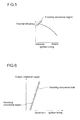
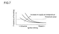
Fig. 6 , as the output or rotational speed is increased, knocking is more likely to occur, and the range where the ignition timing can be advanced. The chart ofFig. 7 indicates that as the supply air temperature increases, the knocking frequency becomes high. Thus, in order not to let the knocking frequency exceed a threshold value, it is necessary to lower the supply air temperature and to retard the ignition timing. On the other hand, as the combustion state or the likelihood of knocking differs depending on the cylinders, it is necessary to set the knocking limit ignition timing of the maximum advance at which knocking does not occur, with respect to each cylinder, depending upon the likelihood of knocking. -
Patent Document 1 discloses an internal combustion engine comprising a plurality of cylinders, having a means for controlling prevention of knocking for each cylinder by adjusting the ignition timing. In this means, knocking is detected by a knock sensor to detect a vibrational state of the cylinder. -
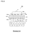
Patent Document 2 discloses a variable compression ratio engine having a means for detecting occurrence of knocking by an in-cylinder pressure sensor and controlling the compression ratio and the ignition timing to prevent knocking, as well as to improve the thermal efficiency and the drivability.Patent Document 3 discloses a gas engine comprising a plurality of cylinders, having a means for detecting a state of knocking (intensity or frequency) which is different depending on the cylinders by measuring an in-cylinder pressure waveform a knocking sensor (e.g. an in-cylinder pressure sensor) provided for each of the cylinders, and changing the air-fuel ratio and the ignition timing based on such a detected value, in order to obtain at least a prescribed value of thermal efficiency without knocking. - In a gas engine comprising a plurality of cylinders, a combustion control device for detecting an in-cylinder pressure waveform by an in-cylinder pressure sensor provided for each cylinder and setting a knocking limit ignition timing may have a configuration as illustrated in
Fig. 8 , for example. InFig. 8 , agas engine 100 has sixcylinders 104a-104f in a row in anengine block 102. Each of thecylinders 104a-104f has an in-cylinder pressure sensor 106. Into each of thecylinders 104a-104f, supply air 'a' is flown from anair cooler 108 via anintake manifold 110. Exhaust gas 'e' after combustion in thecylinders 104a-104f is gathered through anexhaust manifold 112 in anexhaust pipe 114, and then is exhausted from theexhaust pipe 114. - On a crankshaft of the
engine block 102, arotation sensor 116 configured to detect a crank angle including the top dead center and the bottom dead center, is provided. An in-cylinder pressure waveform P corresponding to the crank angle is detected by the in-cylinder pressure sensor 106 and therotation sensor 116. According to a change of the in-cylinder pressure during a cycle, the frequency of knocking and the knocking limit ignition timing are derived. If the ignition timings for all of the cylinders are the same, knocking occurrence may become unsynchronized. By detecting in-cylinder pressures of all of the cylinders, retarding the ignition timings for cylinders in which knocking is likely to occur, and advancing the ignition timings for cylinders in which knocking is unlikely to occur, the ignition timings can be advanced to a maximum extent while knocking is suppressed in all of the cylinders. -
- Patent Document 1:
JP 2011-12569 A - Patent Document 2:
JP H1-100328 A - Patent Document 3:
JP 2002-61524 A - However, since the in-cylinder pressure sensors are expensive, providing an in-cylinder pressure sensors for each of the cylinder leads to a high cost when the number of the cylinder is large. Further, there is also a problem that the probability of failure or malfunction of the in-cylinder pressure sensors may become high.
- In view of the above problem, the present invention is to improve the output and thermal efficiency of a gas engine having a plurality of cylinders by advancing the ignition timing to a maximum extent in each of the plurality of cylinders while knocking is suppressed in the plurality of cylinders by a simple and low-cost means.
- In order to accomplish such an object, the present invention provides a combustion control device for a gas engine having a plurality of cylinders, comprising:
- an in-cylinder pressure sensor configured to detect an in-cylinder pressure of a representing cylinder selected from among the plurality of cylinders,
- a first calculation part for calculating a knocking limit ignition timing of the representing cylinder based on an in-cylinder pressure waveform detected by the in-cylinder pressure sensor,
- a second calculation part for calculating a knocking limit ignition timing of the representing cylinder from a formula containing an operation state quantity other than the in-cylinder pressure waveform, a basic engine specification value and a correction factor,
- a third calculation part for calculating the correction factor by comparing the knocking limit ignition timing of the representing cylinder calculated by the first calculation part and the knocking limit ignition timing of the representing cylinder calculated by the second calculation part,
- a fourth calculation part for calculating a knocking limit ignition timing of a cylinder among the plurality of cylinders other than the representing cylinder by substituting the calculated correction factor, the operation state quantity and the basic engine specification value, into the formula, and
- an ignition timing setting part for setting a knocking limit ignition timing of the each of the plurality of cylinders based on the knocking limit ignition timings of all of the cylinders calculated by the first calculation part and the fourth calculation part.
- According to the present invention, instead of providing an in-cylinder pressure sensor for each of the cylinder, an in-cylinder pressure sensor is provided only for a selected representing cylinder. Since in other cylinders, the knocking limit ignition timing is calculated from another operation state quantity and a basic engine specification value without an in-cylinder pressure sensor provided, it is possible to reduce cost. Further, the knocking limit ignition timing can be calculated for each of the plurality of cylinders from the in-cylinder pressure waveform detected by the in-cylinder pressure sensor and the operation state quantity detected by each of the plurality of cylinders. Thus, it is possible to perform an operation where the fuel consumption and the thermal efficiency are good at a low cost.
- The operation state quantity may be a temperature of supply air supplied to the each of the plurality of cylinders, an air excess ratio or an engine rotational speed. It is thereby possible to reduce sensors provided for the gas engine and reduce cost. The basic engine specification value may be a cylinder bore, a stroke, a compression ratio or a connecting rod length. By adopting such a factor as the basic engine specification, it is possible to accurately calculate the knocking limit ignition timing of each of the plurality of cylinders.
- The fourth calculation part may be configured to modify the correction factor for each of the plurality of cylinders based on a preliminarily obtained operation test data of the gas engine. It is thereby possible to more accurately calculate the knocking limit ignition timing of each of the plurality of cylinders.
- According to the present invention, based on the knocking limit ignition timing of the representing cylinder, the knocking limit ignition timings of cylinders other than the representing cylinder are calculated. Thus, a cylinder in which knocking is most likely to occur among the plurality of cylinders may be selected as the representing cylinder, whereby it is possible to advance the ignition timing from an operation state on a safe side where knocking is certainly suppressed and to adjust it to the knocking limit ignition timing.
- According to the present invention, by a low-cost means where an in-cylinder pressure sensor is provided only for a selected representing cylinder instead of providing an in-cylinder pressure sensor for each of the cylinder, the knocking limit ignition timing of each of the plurality of cylinders can be calculated for each of the plurality of cylinders from the in-cylinder pressure waveform of the representing cylinder, and the operation state quantity and the basic engine specification value of each of the plurality of cylinders. Thus, it is possible to advance the ignition timing to a maximum extent while knocking is suppressed in each of the plurality of cylinders and thereby to improve the output and thermal efficiency of the gas engine.
-
-
FIG. 1 is a configuration diagram of a gas engine according to an embodiment of the present invention. -
FIG. 2 is a block diagram illustrating a combustion control device according to the above embodiment. -
FIG. 3 is a flowchart illustrating a procedure of a combustion control according the above embodiment. -
FIG. 4 is a chart showing variation in knocking frequencies among cylinders of an gas engine. -
FIG. 5 is a chart showing a relationship between an ignition timing and a thermal efficiency of a gas engine. -
FIG. 6 is a chart showing a relationship between an output and a rotational speed at an ignition timing, and a knocking occurrence limit, of a gas engine. -
FIG. 7 is a chart showing a relationship between a supply air temperature and a knocking frequency of a gas engine. -
FIG. 8 is a configuration diagram of a combustion control device of a gas engine in a case of an in-cylinder pressure sensor is provided for each cylinder (related art). - Embodiments of the present invention will now be described in detail with reference to the accompanying drawings. It is intended, however, that unless particularly specified, dimensions, materials, shapes, relative positions and the like of components described in the embodiments shall be interpreted as illustrative only and not limitative of the scope of the present invention.
- An embodiment where the present invention is applied to a combustion control of a gas engine will be described with reference to
Fig. 1 to Fig. 4 . As illustrated inFig. 1 , agas engine 10 according to this embodiment has sixcylinders 14a-14f in a row in anengine block 12. Among thecylinders 14a-14f, theleftmost cylinder 14a is selected as a representing cylinder. Thecylinder 14a is provided with an in-cylinder pressure sensor 16. Into each of thecylinders 14a-14f, a supply air 'a' is flown from anair cooler 18 via anintake manifold 20. An exhaust gas 'e' after combustion in each of thecylinders 14a-14f is gathered into anexhaust pipe 24 via anexhaust manifold 22, and then is exhausted from theexhaust pipe 24. - On a crankshaft (not shown) of the
engine block 12, arotation sensor 26 configured to detect a crank angle including a top dead center and a bottom dead center, is provided. An in-cylinder pressure waveform P corresponding to the crank angle is detected by the in-cylinder pressure sensor 16 and therotation sensor 26. Based on a change of the in-cylinder pressure during each cycle, the knocking occurrence frequency and the knocking limit ignition timing are derived. Supplyair temperature sensors 28a-28f are provided at the inlets of therespective cylinders 14a-14f. As illustrated inFig. 1 , the supply air temperatures Ts of the intake air into therespective cylinders 14a-14f are different. The supply air temperatures Ts of thecylinder 14a and thecylinder 14f at the both ends of the row of the cylinders are the highest, and the supply air temperatures Ts of thecylinder 14c and thecylinder 14d at the center are the lowest. - In the
air cooler 18 or theintake manifold 20, since the supply air tends to remain at the both ends, the wall temperature is likely to be high. Thus, the temperatures Ts of the supply air flown into thecylinder 14a and thecylinder 14f disposed at the both ends of theengine block 12 are most likely to be high. Therefore, knocking becomes likely to occur in the cylinders disposed at the both ends of theengine block 12. In this embodiment, theleftmost cylinder 14a is selected as the representing cylinder. -
Fig. 2 illustrates acombustion control device 30 of thegas engine 10. As illustrated inFig. 2 , an in-cylinder pressure waveform of the representingcylinder 14a detected by the in-cylinder pressure sensor 16 is input into afirst calculation part 32. In thefirst calculation part 32, a knocking limit ignition timing of the representingcylinder 14a is calculated based on the in-cylinder pressure waveform. In thesecond calculation part 34, a knocking limit ignition timing of the representingcylinder 14a is calculated from the following formula (1) containing an operation state quantity, a basic engine specification value and a correction factor C:
where C is correction factor; B is cylinder bore, S is stroke, ε is compression ratio, and CR is connecting rod length, which are basic engine specification values; and Ne is engine rotational speed, λ is air excess ratio, and Ts is supply air temperature, which are operation state quantities. - The engine rotational speed Ne is detected by the
rotation sensor 26, and the supply air temperature is detected for each of the cylinders by each of thesensors 28a-28f. Regarding the air excess ratio λ, it is preferred to confirm whether the air excess ratio λ is as set, by an oxygen concentration sensor provided on an exhaust passage. In a case where a gas fuel is supplied before the compressor, it is enough to provide one oxygen concentration sensor in theexhaust pipe 24 because there will be no variation among the cylinders. - In the
third calculation part 36, the knocking limit ignition timing of the representingcylinder 14a calculated by thefirst calculation part 32 and the knocking limit ignition timing of the representingcylinder 14a calculated by thesecond calculation part 34 are compared, to obtain a correction factor C. In thefourth calculation part 38, based on the correction factor C obtained by thethird calculation part 36, the operation state quantity and the basic engine specification value are substituted into the formula (1) for each of the cylinders to calculate the knocking limit ignition timing of each of the cylinders other than the representingcylinder 14a. In the ignitiontiming setting part 40, a knocking limit ignition timing of an ignition device (not shown) of each of the cylinders is set based on the calculated knocking limit ignition timing of each of the cylinders. -
Fig. 3 is a flowchart illustrating a procedure of setting a knocking limit ignition timing by thecontrol device 30. As illustrated inFig. 3 , first, an in-cylinder pressure waveform of the representingcylinder 14a is detected by the in-cylinder pressure sensor 16 (S10). Then, in thefirst calculation part 32, a knocking limit ignition timing Tia of the representingcylinder 14a is calculated based on the detected in-cylinder pressure waveform (S12). Meanwhile, as described above, as the operation state quantities, an engine rotational speed Ne, an air excess ratio λ, and a supply air temperature Ts of each of the cylinders obtained by sensors provided for thegas engine 10, are selected (S 14). These operation state quantities and the basic engine specification values are input into thesecond calculation part 34. In thesecond calculation part 34, a knocking limit ignition timing Tia' of the representingcylinder 14a is calculated from the formula (1) (S16). - Then, in the
third calculation part 36, the knocking limit ignition timing Tia calculated by thefirst calculation part 32 and the knocking limit ignition timing Tia' calculated by thesecond calculation part 34 are compared to calculate a correction factor C (S18). That is, the knocking limit ignition timing Tia, and the operation state quantities and the basic engine specification values are substituted into the formula (1) to obtain the correction factor C. Then, based on the obtained correction factor C, and the operation state quantities and the basic engine specification values of each of the cylinders, knocking limit ignition timings Tib-Tif are calculated from the formula (1) (S20). Operation test data of a test machine of the same type as thegas engine 10 are obtained in advance. Based on the test data, the correction factor C is modified for each of the cylinders. Based on the modified correction factor C, knocking limit ignition timings Tib -Tif are calculated. -
Fig. 4 is a chart showing variation in knocking frequencies among cylinders of an gas engine, obtained based on test data of a test machine under a condition of a constant supply air temperature. For example, the knocking frequencies are varied among the cylinders due to difference in the supply air temperatures Ts. However, even if the supply air temperatures Ts are actually the same among the cylinders, the knocking frequencies may be varied among the cylinders due to difference in the temperatures of wall surface of combustion chambers of the respective cylinders. Thus, in order to calculate an accurate knocking limit ignition timing for each of the cylinders, the correction factor C may be modified for each of the cylinders. - Based on the knocking limit ignition timings of the
respective cylinders 14a-14f calculated as above, ignition timings of therespective cylinders 14a-14f of the ignition device are set by the ignitiontiming setting part 40. In this way, the ignition timings of the respective cylinders are changed on a real time basis while the in-cylinder pressure waveform of the representingcylinder 14a and another operation quantity are detected from moment to moment. - According to this embodiment, it is enough to provide the in-
cylinder pressure sensor 16 only for the selected representingcylinder 14a, and the knocking limit ignition timing is calculated without providing in-cylinder pressure sensors forother cylinders 14b-14f, whereby it is possible to reduce cost. Further, the knocking limit ignition timing of each of the cylinder is calculated based on the in-cylinder pressure waveform of the representingcylinder 14a detected by the in-cylinder pressure sensor 16, and another operation state quantity detected for each of the cylinders and the basic engine specification value, whereby it is possible to perform operation where the thermal efficiency is good. - Further, since the correction factor C is modified for each of the cylinders based on operation test data preliminarily obtained from a test machine of the same type as the
gas engine 10, it is possible to calculate an accurate knocking limit ignition timing of each of the cylinders. Further, since thecylinder 14a in which the supply air temperature Ts is the highest and knocking is most likely to occur, is selected as the representing cylinder, and the knocking limit ignition timings of the other cylinders are calculated based on the knocking limit ignition timing of thecylinder 14a, it is possible to advance the ignition timing from an operation state on a safe side and to adjust it to the knocking limit ignition timing, and it is possible to certainly suppress knocking. - According to the present invention, it is possible to advance the ignition timing to a maximum extent while knocking is suppressed, in each of the plurality of cylinders, and thereby to improve the output and thermal efficiency of a gas engine, by a simple and low-cost means.
Claims (4)
- A combustion control device for a gas engine having a plurality of cylinders, comprising:an in-cylinder pressure sensor configured to detect an in-cylinder pressure of a representing cylinder selected from among the plurality of cylinders,a first calculation part for calculating a knocking limit ignition timing of the representing cylinder based on an in-cylinder pressure waveform detected by the in-cylinder pressure sensor,a second calculation part for calculating a knocking limit ignition timing of the representing cylinder from a formula containing an operation state quantity other than the in-cylinder pressure waveform, a basic engine specification value and a correction factor,a third calculation part for calculating the correction factor by comparing the knocking limit ignition timing of the representing cylinder calculated by the first calculation part and the knocking limit ignition timing of the representing cylinder calculated by the second calculation part,a fourth calculation part for calculating a knocking limit ignition timing of a cylinder among the plurality of cylinders other than the representing cylinder by substituting the calculated correction factor, the operation state quantity and the basic engine specification value, into the formula, andan ignition timing setting part for setting a knocking limit ignition timing of the each of the plurality of cylinders based on the knocking limit ignition timings of all of the cylinders calculated by the first calculation part and the fourth calculation part.
- The combustion control device for a gas engine according to claim 1, wherein the operation state quantity includes a temperature of supply air supplied to the each of the plurality of cylinders, an air excess ratio or an engine rotational speed, and the basic engine specification value includes a cylinder bore, a stroke, a compression ratio or a connecting rod length.
- The combustion control device according to claim 1 or 2, wherein the fourth calculation part is configured to modify the correction factor for each of the plurality of cylinders based on a preliminarily obtained operation test data of the gas engine.
- The combustion control device according to claim 1, wherein a cylinder in which knocking is most likely to occur among the plurality of cylinders is selected as the representing cylinder.
Applications Claiming Priority (2)
| Application Number | Priority Date | Filing Date | Title |
|---|---|---|---|
| JP2011289213A JP5836114B2 (en) | 2011-12-28 | 2011-12-28 | Gas engine combustion control device |
| PCT/JP2012/081643 WO2013099552A1 (en) | 2011-12-28 | 2012-12-06 | Combustion control device for gas engine |
Publications (3)
| Publication Number | Publication Date |
|---|---|
| EP2799708A1 true EP2799708A1 (en) | 2014-11-05 |
| EP2799708A4 EP2799708A4 (en) | 2016-05-18 |
| EP2799708B1 EP2799708B1 (en) | 2018-10-17 |
Family
ID=48697048
Family Applications (1)
| Application Number | Title | Priority Date | Filing Date |
|---|---|---|---|
| EP12863802.0A Not-in-force EP2799708B1 (en) | 2011-12-28 | 2012-12-06 | Combustion control device for gas engine |
Country Status (6)
| Country | Link |
|---|---|
| US (1) | US9234818B2 (en) |
| EP (1) | EP2799708B1 (en) |
| JP (1) | JP5836114B2 (en) |
| KR (1) | KR101584025B1 (en) |
| CN (1) | CN103998767B (en) |
| WO (1) | WO2013099552A1 (en) |
Cited By (1)
| Publication number | Priority date | Publication date | Assignee | Title |
|---|---|---|---|---|
| EP3369923A4 (en) * | 2015-10-30 | 2019-05-22 | Kawasaki Jukogyo Kabushiki Kaisha | METHOD FOR CONTROLLING GAS ENGINE |
Families Citing this family (9)
| Publication number | Priority date | Publication date | Assignee | Title |
|---|---|---|---|---|
| ITBO20120323A1 (en) * | 2012-06-12 | 2013-12-13 | Magneti Marelli Spa | METHOD OF CONTROL OF AN INTERNAL COMBUSTION ENGINE |
| US10087863B2 (en) * | 2014-12-24 | 2018-10-02 | Keihin Corporation | Internal combustion engine control device |
| JP6312618B2 (en) * | 2015-03-13 | 2018-04-18 | 日立オートモティブシステムズ株式会社 | Internal combustion engine control device and abnormal combustion detection method |
| JP6315003B2 (en) * | 2016-02-08 | 2018-04-25 | トヨタ自動車株式会社 | Control device for internal combustion engine |
| US10371116B2 (en) * | 2017-12-08 | 2019-08-06 | GM Global Technology Operations LLC | Method and apparatus for controlling a multi-cylinder internal combustion engine |
| CN115803519B (en) * | 2020-06-12 | 2025-03-14 | 日产自动车株式会社 | Engine control method and control device |
| CN112648090A (en) * | 2021-01-12 | 2021-04-13 | 重庆航控科技有限公司 | Engine control system and method and engine |
| CN115306571B (en) * | 2022-07-06 | 2024-05-17 | 潍柴动力股份有限公司 | Control method and control system for nitrogen oxide emission of gas engine |
| US20260063099A1 (en) * | 2024-08-29 | 2026-03-05 | Caterpillar Inc. | Systems and methods for adaptively managing engine knocking |
Family Cites Families (25)
| Publication number | Priority date | Publication date | Assignee | Title |
|---|---|---|---|---|
| DE3050875C2 (en) * | 1979-06-15 | 1992-05-27 | Nissan Motor Co., Ltd., Yokohama, Kanagawa | Device for detecting knocking phenomena of an internal combustion engine |
| JPH07113356B2 (en) * | 1987-06-01 | 1995-12-06 | 日産自動車株式会社 | Ignition timing control device for internal combustion engine |
| JPH01100328A (en) | 1987-10-09 | 1989-04-18 | Fuji Heavy Ind Ltd | Variable-compression ratio type engine |
| DE3825787A1 (en) * | 1988-07-29 | 1990-02-01 | Philips Nv | PROCESS FOR PRODUCING IRON GREEN LAYERS |
| JPH0364653A (en) | 1989-07-31 | 1991-03-20 | Japan Electron Control Syst Co Ltd | Pressure in cylinder detection device of internal combustion engine |
| JP3579933B2 (en) * | 1994-11-09 | 2004-10-20 | 日産自動車株式会社 | Internal combustion engine combustion state control device |
| DE19536168B4 (en) * | 1995-09-29 | 2008-05-15 | Siemens Ag | Method and device for automatically determining the knock limit of an internal combustion engine on a test bench |
| DE19709395C2 (en) * | 1997-03-07 | 1998-12-24 | Bosch Gmbh Robert | Knock control method in multi-cylinder internal combustion engines |
| DE19927846C2 (en) * | 1999-06-18 | 2001-09-13 | Mtu Friedrichshafen Gmbh | Method for monitoring an internal combustion engine |
| JP4326131B2 (en) | 2000-08-18 | 2009-09-02 | ヤンマー株式会社 | Gas engine control device and control method |
| JP3975936B2 (en) | 2003-02-17 | 2007-09-12 | 日産自動車株式会社 | Knocking index value calculation device |
| DE10360201A1 (en) * | 2003-12-20 | 2005-07-21 | Robert Bosch Gmbh | Method for calculating an ignition angle of an internal combustion engine |
| US7021286B2 (en) * | 2004-02-20 | 2006-04-04 | Nissan Motor Co., Ltd. | Ignition timing control for internal combustion engine |
| JP4075818B2 (en) * | 2004-02-20 | 2008-04-16 | 日産自動車株式会社 | Ignition timing control device for internal combustion engine |
| DE502005009083D1 (en) * | 2004-03-01 | 2010-04-08 | Bosch Gmbh Robert | METHOD AND DEVICE FOR DETERMINING A WINKELLING SIGNAL ON AN INTERNAL COMBUSTION ENGINE |
| JP4301993B2 (en) * | 2004-04-27 | 2009-07-22 | 三菱重工業株式会社 | Gas engine and ignition timing control / storage device |
| GB0410135D0 (en) * | 2004-05-06 | 2004-06-09 | Ricardo Uk Ltd | Cylinder pressure sensor |
| US6947830B1 (en) * | 2004-08-31 | 2005-09-20 | Walt Froloff | Adaptive variable fuel internal combustion engine |
| JP4888890B2 (en) * | 2006-06-02 | 2012-02-29 | 本田技研工業株式会社 | Knocking control device for multi-cylinder engine |
| JP4773888B2 (en) * | 2006-06-02 | 2011-09-14 | 本田技研工業株式会社 | Ignition timing control device for internal combustion engine |
| JP4841638B2 (en) | 2009-02-12 | 2011-12-21 | 本田技研工業株式会社 | Ignition timing control device for internal combustion engine |
| US8191532B2 (en) * | 2009-03-27 | 2012-06-05 | GM Global Technology Operations LLC | Method and system for detecting and reducing engine auto-ignition |
| JP2011012569A (en) | 2009-06-30 | 2011-01-20 | Toyota Motor Corp | Internal combustion engine knocking control device |
| GB2473438B (en) * | 2009-09-09 | 2013-07-31 | Gm Global Tech Operations Inc | Method and device for closed-loop combustion control for an internal combustion engine |
| JP2012002088A (en) * | 2010-06-15 | 2012-01-05 | Nippon Soken Inc | Control device of internal combustion engine |
-
2011
- 2011-12-28 JP JP2011289213A patent/JP5836114B2/en not_active Expired - Fee Related
-
2012
- 2012-12-06 WO PCT/JP2012/081643 patent/WO2013099552A1/en not_active Ceased
- 2012-12-06 EP EP12863802.0A patent/EP2799708B1/en not_active Not-in-force
- 2012-12-06 US US14/367,051 patent/US9234818B2/en not_active Expired - Fee Related
- 2012-12-06 KR KR1020147016508A patent/KR101584025B1/en not_active Expired - Fee Related
- 2012-12-06 CN CN201280062587.8A patent/CN103998767B/en not_active Expired - Fee Related
Cited By (1)
| Publication number | Priority date | Publication date | Assignee | Title |
|---|---|---|---|---|
| EP3369923A4 (en) * | 2015-10-30 | 2019-05-22 | Kawasaki Jukogyo Kabushiki Kaisha | METHOD FOR CONTROLLING GAS ENGINE |
Also Published As
| Publication number | Publication date |
|---|---|
| CN103998767B (en) | 2016-09-07 |
| US20140366842A1 (en) | 2014-12-18 |
| EP2799708B1 (en) | 2018-10-17 |
| JP5836114B2 (en) | 2015-12-24 |
| WO2013099552A1 (en) | 2013-07-04 |
| JP2013137003A (en) | 2013-07-11 |
| EP2799708A4 (en) | 2016-05-18 |
| US9234818B2 (en) | 2016-01-12 |
| KR101584025B1 (en) | 2016-01-08 |
| KR20140095094A (en) | 2014-07-31 |
| CN103998767A (en) | 2014-08-20 |
Similar Documents
| Publication | Publication Date | Title |
|---|---|---|
| EP2799708A1 (en) | Combustion control device for gas engine | |
| US10001071B2 (en) | Control system and control method for internal combustion engine | |
| CA2889605C (en) | Detecting and mitigating abnormal combustion characteristics | |
| US20120186225A1 (en) | Methods And Apparatus To Detect And Inhibit Low-Speed Pre-Ignition In An Engine | |
| JP5758862B2 (en) | In-cylinder pressure detection device for internal combustion engine | |
| US20180066593A1 (en) | Control Device for Internal Combustion Engine and Abnormal Combustion Detecting Method | |
| JP2017141693A (en) | Control device of internal combustion engine | |
| US9903302B2 (en) | Control device for internal combustion engine | |
| JP2005291182A (en) | Misfire detection device | |
| US20120290189A1 (en) | Compression ratio determination and control systems and methods | |
| JP2017025777A (en) | Control device of internal combustion engine | |
| JPWO2013069157A1 (en) | In-cylinder pressure sensor abnormality diagnosis device and in-cylinder pressure sensor sensitivity correction device including the same | |
| WO2015133172A1 (en) | Air-fuel ratio detection device for internal combustion engine | |
| JP2011157852A (en) | Control device of internal combustion engine | |
| JP2012207656A (en) | Control device of internal combustion engine | |
| JP4507975B2 (en) | Engine control device | |
| JP2014005819A (en) | Internal egr amount calculating device for internal combustion engine | |
| JP2018172994A (en) | Internal combustion engine control device | |
| JP2012180817A (en) | Device for calculating air-fuel ratio of internal combustion engine | |
| JP5488286B2 (en) | Combustion state detection system for internal combustion engine | |
| JP2005180356A (en) | Crank angle sensor correction device and correction method | |
| JP4345723B2 (en) | Method for estimating the indicated mean effective pressure of an internal combustion engine | |
| JP2017141745A (en) | Control device of internal combustion engine | |
| JP6456273B2 (en) | Control device for internal combustion engine | |
| JP2021124071A (en) | Control device of internal combustion engine |
Legal Events
| Date | Code | Title | Description |
|---|---|---|---|
| PUAI | Public reference made under article 153(3) epc to a published international application that has entered the european phase |
Free format text: ORIGINAL CODE: 0009012 |
|
| 17P | Request for examination filed |
Effective date: 20140620 |
|
| AK | Designated contracting states |
Kind code of ref document: A1 Designated state(s): AL AT BE BG CH CY CZ DE DK EE ES FI FR GB GR HR HU IE IS IT LI LT LU LV MC MK MT NL NO PL PT RO RS SE SI SK SM TR |
|
| DAX | Request for extension of the european patent (deleted) | ||
| RA4 | Supplementary search report drawn up and despatched (corrected) |
Effective date: 20160418 |
|
| RIC1 | Information provided on ipc code assigned before grant |
Ipc: F02D 19/02 20060101ALI20160412BHEP Ipc: F02D 41/00 20060101ALN20160412BHEP Ipc: F02D 45/00 20060101ALI20160412BHEP Ipc: F02D 35/02 20060101ALN20160412BHEP Ipc: F02M 21/02 20060101ALI20160412BHEP Ipc: F02P 5/152 20060101AFI20160412BHEP Ipc: F02P 5/153 20060101ALI20160412BHEP |
|
| RIC1 | Information provided on ipc code assigned before grant |
Ipc: F02D 35/02 20060101ALN20180614BHEP Ipc: F02P 5/153 20060101ALI20180614BHEP Ipc: F02D 45/00 20060101ALI20180614BHEP Ipc: F02D 19/02 20060101ALI20180614BHEP Ipc: F02M 21/02 20060101ALI20180614BHEP Ipc: F02D 41/00 20060101ALN20180614BHEP Ipc: F02P 5/152 20060101AFI20180614BHEP |
|
| GRAP | Despatch of communication of intention to grant a patent |
Free format text: ORIGINAL CODE: EPIDOSNIGR1 |
|
| INTG | Intention to grant announced |
Effective date: 20180720 |
|
| GRAS | Grant fee paid |
Free format text: ORIGINAL CODE: EPIDOSNIGR3 |
|
| GRAA | (expected) grant |
Free format text: ORIGINAL CODE: 0009210 |
|
| AK | Designated contracting states |
Kind code of ref document: B1 Designated state(s): AL AT BE BG CH CY CZ DE DK EE ES FI FR GB GR HR HU IE IS IT LI LT LU LV MC MK MT NL NO PL PT RO RS SE SI SK SM TR |
|
| REG | Reference to a national code |
Ref country code: GB Ref legal event code: FG4D |
|
| REG | Reference to a national code |
Ref country code: CH Ref legal event code: EP |
|
| REG | Reference to a national code |
Ref country code: IE Ref legal event code: FG4D |
|
| REG | Reference to a national code |
Ref country code: DE Ref legal event code: R096 Ref document number: 602012052436 Country of ref document: DE Ref country code: AT Ref legal event code: REF Ref document number: 1054335 Country of ref document: AT Kind code of ref document: T Effective date: 20181115 |
|
| REG | Reference to a national code |
Ref country code: NL Ref legal event code: MP Effective date: 20181017 |
|
| REG | Reference to a national code |
Ref country code: LT Ref legal event code: MG4D |
|
| PG25 | Lapsed in a contracting state [announced via postgrant information from national office to epo] |
Ref country code: NL Free format text: LAPSE BECAUSE OF FAILURE TO SUBMIT A TRANSLATION OF THE DESCRIPTION OR TO PAY THE FEE WITHIN THE PRESCRIBED TIME-LIMIT Effective date: 20181017 |
|
| PG25 | Lapsed in a contracting state [announced via postgrant information from national office to epo] |
Ref country code: BG Free format text: LAPSE BECAUSE OF FAILURE TO SUBMIT A TRANSLATION OF THE DESCRIPTION OR TO PAY THE FEE WITHIN THE PRESCRIBED TIME-LIMIT Effective date: 20190117 Ref country code: LT Free format text: LAPSE BECAUSE OF FAILURE TO SUBMIT A TRANSLATION OF THE DESCRIPTION OR TO PAY THE FEE WITHIN THE PRESCRIBED TIME-LIMIT Effective date: 20181017 Ref country code: IS Free format text: LAPSE BECAUSE OF FAILURE TO SUBMIT A TRANSLATION OF THE DESCRIPTION OR TO PAY THE FEE WITHIN THE PRESCRIBED TIME-LIMIT Effective date: 20190217 Ref country code: NO Free format text: LAPSE BECAUSE OF FAILURE TO SUBMIT A TRANSLATION OF THE DESCRIPTION OR TO PAY THE FEE WITHIN THE PRESCRIBED TIME-LIMIT Effective date: 20190117 Ref country code: LV Free format text: LAPSE BECAUSE OF FAILURE TO SUBMIT A TRANSLATION OF THE DESCRIPTION OR TO PAY THE FEE WITHIN THE PRESCRIBED TIME-LIMIT Effective date: 20181017 Ref country code: ES Free format text: LAPSE BECAUSE OF FAILURE TO SUBMIT A TRANSLATION OF THE DESCRIPTION OR TO PAY THE FEE WITHIN THE PRESCRIBED TIME-LIMIT Effective date: 20181017 Ref country code: PL Free format text: LAPSE BECAUSE OF FAILURE TO SUBMIT A TRANSLATION OF THE DESCRIPTION OR TO PAY THE FEE WITHIN THE PRESCRIBED TIME-LIMIT Effective date: 20181017 Ref country code: HR Free format text: LAPSE BECAUSE OF FAILURE TO SUBMIT A TRANSLATION OF THE DESCRIPTION OR TO PAY THE FEE WITHIN THE PRESCRIBED TIME-LIMIT Effective date: 20181017 |
|
| PG25 | Lapsed in a contracting state [announced via postgrant information from national office to epo] |
Ref country code: PT Free format text: LAPSE BECAUSE OF FAILURE TO SUBMIT A TRANSLATION OF THE DESCRIPTION OR TO PAY THE FEE WITHIN THE PRESCRIBED TIME-LIMIT Effective date: 20190217 Ref country code: AL Free format text: LAPSE BECAUSE OF FAILURE TO SUBMIT A TRANSLATION OF THE DESCRIPTION OR TO PAY THE FEE WITHIN THE PRESCRIBED TIME-LIMIT Effective date: 20181017 Ref country code: SE Free format text: LAPSE BECAUSE OF FAILURE TO SUBMIT A TRANSLATION OF THE DESCRIPTION OR TO PAY THE FEE WITHIN THE PRESCRIBED TIME-LIMIT Effective date: 20181017 Ref country code: GR Free format text: LAPSE BECAUSE OF FAILURE TO SUBMIT A TRANSLATION OF THE DESCRIPTION OR TO PAY THE FEE WITHIN THE PRESCRIBED TIME-LIMIT Effective date: 20190118 Ref country code: RS Free format text: LAPSE BECAUSE OF FAILURE TO SUBMIT A TRANSLATION OF THE DESCRIPTION OR TO PAY THE FEE WITHIN THE PRESCRIBED TIME-LIMIT Effective date: 20181017 |
|
| REG | Reference to a national code |
Ref country code: DE Ref legal event code: R097 Ref document number: 602012052436 Country of ref document: DE |
|
| PG25 | Lapsed in a contracting state [announced via postgrant information from national office to epo] |
Ref country code: IT Free format text: LAPSE BECAUSE OF FAILURE TO SUBMIT A TRANSLATION OF THE DESCRIPTION OR TO PAY THE FEE WITHIN THE PRESCRIBED TIME-LIMIT Effective date: 20181017 Ref country code: CZ Free format text: LAPSE BECAUSE OF FAILURE TO SUBMIT A TRANSLATION OF THE DESCRIPTION OR TO PAY THE FEE WITHIN THE PRESCRIBED TIME-LIMIT Effective date: 20181017 Ref country code: DK Free format text: LAPSE BECAUSE OF FAILURE TO SUBMIT A TRANSLATION OF THE DESCRIPTION OR TO PAY THE FEE WITHIN THE PRESCRIBED TIME-LIMIT Effective date: 20181017 |
|
| REG | Reference to a national code |
Ref country code: CH Ref legal event code: PL |
|
| PLBE | No opposition filed within time limit |
Free format text: ORIGINAL CODE: 0009261 |
|
| STAA | Information on the status of an ep patent application or granted ep patent |
Free format text: STATUS: NO OPPOSITION FILED WITHIN TIME LIMIT |
|
| PG25 | Lapsed in a contracting state [announced via postgrant information from national office to epo] |
Ref country code: EE Free format text: LAPSE BECAUSE OF FAILURE TO SUBMIT A TRANSLATION OF THE DESCRIPTION OR TO PAY THE FEE WITHIN THE PRESCRIBED TIME-LIMIT Effective date: 20181017 Ref country code: SM Free format text: LAPSE BECAUSE OF FAILURE TO SUBMIT A TRANSLATION OF THE DESCRIPTION OR TO PAY THE FEE WITHIN THE PRESCRIBED TIME-LIMIT Effective date: 20181017 Ref country code: RO Free format text: LAPSE BECAUSE OF FAILURE TO SUBMIT A TRANSLATION OF THE DESCRIPTION OR TO PAY THE FEE WITHIN THE PRESCRIBED TIME-LIMIT Effective date: 20181017 Ref country code: MC Free format text: LAPSE BECAUSE OF FAILURE TO SUBMIT A TRANSLATION OF THE DESCRIPTION OR TO PAY THE FEE WITHIN THE PRESCRIBED TIME-LIMIT Effective date: 20181017 Ref country code: LU Free format text: LAPSE BECAUSE OF NON-PAYMENT OF DUE FEES Effective date: 20181206 Ref country code: SK Free format text: LAPSE BECAUSE OF FAILURE TO SUBMIT A TRANSLATION OF THE DESCRIPTION OR TO PAY THE FEE WITHIN THE PRESCRIBED TIME-LIMIT Effective date: 20181017 |
|
| REG | Reference to a national code |
Ref country code: IE Ref legal event code: MM4A |
|
| 26N | No opposition filed |
Effective date: 20190718 |
|
| GBPC | Gb: european patent ceased through non-payment of renewal fee |
Effective date: 20190117 |
|
| REG | Reference to a national code |
Ref country code: BE Ref legal event code: MM Effective date: 20181231 |
|
| PG25 | Lapsed in a contracting state [announced via postgrant information from national office to epo] |
Ref country code: IE Free format text: LAPSE BECAUSE OF NON-PAYMENT OF DUE FEES Effective date: 20181206 Ref country code: FR Free format text: LAPSE BECAUSE OF NON-PAYMENT OF DUE FEES Effective date: 20181217 Ref country code: SI Free format text: LAPSE BECAUSE OF FAILURE TO SUBMIT A TRANSLATION OF THE DESCRIPTION OR TO PAY THE FEE WITHIN THE PRESCRIBED TIME-LIMIT Effective date: 20181017 |
|
| PG25 | Lapsed in a contracting state [announced via postgrant information from national office to epo] |
Ref country code: BE Free format text: LAPSE BECAUSE OF NON-PAYMENT OF DUE FEES Effective date: 20181231 |
|
| PG25 | Lapsed in a contracting state [announced via postgrant information from national office to epo] |
Ref country code: GB Free format text: LAPSE BECAUSE OF NON-PAYMENT OF DUE FEES Effective date: 20190117 Ref country code: LI Free format text: LAPSE BECAUSE OF NON-PAYMENT OF DUE FEES Effective date: 20181231 Ref country code: CH Free format text: LAPSE BECAUSE OF NON-PAYMENT OF DUE FEES Effective date: 20181231 |
|
| PG25 | Lapsed in a contracting state [announced via postgrant information from national office to epo] |
Ref country code: MT Free format text: LAPSE BECAUSE OF NON-PAYMENT OF DUE FEES Effective date: 20181206 |
|
| PG25 | Lapsed in a contracting state [announced via postgrant information from national office to epo] |
Ref country code: TR Free format text: LAPSE BECAUSE OF FAILURE TO SUBMIT A TRANSLATION OF THE DESCRIPTION OR TO PAY THE FEE WITHIN THE PRESCRIBED TIME-LIMIT Effective date: 20181017 |
|
| PG25 | Lapsed in a contracting state [announced via postgrant information from national office to epo] |
Ref country code: MK Free format text: LAPSE BECAUSE OF NON-PAYMENT OF DUE FEES Effective date: 20181017 Ref country code: HU Free format text: LAPSE BECAUSE OF FAILURE TO SUBMIT A TRANSLATION OF THE DESCRIPTION OR TO PAY THE FEE WITHIN THE PRESCRIBED TIME-LIMIT; INVALID AB INITIO Effective date: 20121206 Ref country code: CY Free format text: LAPSE BECAUSE OF FAILURE TO SUBMIT A TRANSLATION OF THE DESCRIPTION OR TO PAY THE FEE WITHIN THE PRESCRIBED TIME-LIMIT Effective date: 20181017 |
|
| PGFP | Annual fee paid to national office [announced via postgrant information from national office to epo] |
Ref country code: FI Payment date: 20201209 Year of fee payment: 9 Ref country code: DE Payment date: 20201124 Year of fee payment: 9 Ref country code: AT Payment date: 20201125 Year of fee payment: 9 |
|
| REG | Reference to a national code |
Ref country code: AT Ref legal event code: UEP Ref document number: 1054335 Country of ref document: AT Kind code of ref document: T Effective date: 20181017 |
|
| REG | Reference to a national code |
Ref country code: DE Ref legal event code: R119 Ref document number: 602012052436 Country of ref document: DE |
|
| REG | Reference to a national code |
Ref country code: FI Ref legal event code: MAE |
|
| REG | Reference to a national code |
Ref country code: AT Ref legal event code: MM01 Ref document number: 1054335 Country of ref document: AT Kind code of ref document: T Effective date: 20211206 |
|
| PG25 | Lapsed in a contracting state [announced via postgrant information from national office to epo] |
Ref country code: FI Free format text: LAPSE BECAUSE OF NON-PAYMENT OF DUE FEES Effective date: 20211206 |
|
| PG25 | Lapsed in a contracting state [announced via postgrant information from national office to epo] |
Ref country code: DE Free format text: LAPSE BECAUSE OF NON-PAYMENT OF DUE FEES Effective date: 20220701 Ref country code: AT Free format text: LAPSE BECAUSE OF NON-PAYMENT OF DUE FEES Effective date: 20211206 |