EP2799631A2 - Assembly for securing a wear member - Google Patents
Assembly for securing a wear member Download PDFInfo
- Publication number
- EP2799631A2 EP2799631A2 EP20140179216 EP14179216A EP2799631A2 EP 2799631 A2 EP2799631 A2 EP 2799631A2 EP 20140179216 EP20140179216 EP 20140179216 EP 14179216 A EP14179216 A EP 14179216A EP 2799631 A2 EP2799631 A2 EP 2799631A2
- Authority
- EP
- European Patent Office
- Prior art keywords
- base
- paragraph
- accordance
- wear member
- adapter
- Prior art date
- Legal status (The legal status is an assumption and is not a legal conclusion. Google has not performed a legal analysis and makes no representation as to the accuracy of the status listed.)
- Granted
Links
Images


Classifications
-
- E—FIXED CONSTRUCTIONS
- E02—HYDRAULIC ENGINEERING; FOUNDATIONS; SOIL SHIFTING
- E02F—DREDGING; SOIL-SHIFTING
- E02F9/00—Component parts of dredgers or soil-shifting machines, not restricted to one of the kinds covered by groups E02F3/00 - E02F7/00
- E02F9/28—Small metalwork for digging elements, e.g. teeth scraper bits
- E02F9/2808—Teeth
- E02F9/2816—Mountings therefor
- E02F9/2825—Mountings therefor using adapters
-
- E—FIXED CONSTRUCTIONS
- E02—HYDRAULIC ENGINEERING; FOUNDATIONS; SOIL SHIFTING
- E02F—DREDGING; SOIL-SHIFTING
- E02F9/00—Component parts of dredgers or soil-shifting machines, not restricted to one of the kinds covered by groups E02F3/00 - E02F7/00
- E02F9/28—Small metalwork for digging elements, e.g. teeth scraper bits
- E02F9/2808—Teeth
- E02F9/2816—Mountings therefor
- E02F9/2833—Retaining means, e.g. pins
- E02F9/2841—Retaining means, e.g. pins resilient
-
- E—FIXED CONSTRUCTIONS
- E02—HYDRAULIC ENGINEERING; FOUNDATIONS; SOIL SHIFTING
- E02F—DREDGING; SOIL-SHIFTING
- E02F9/00—Component parts of dredgers or soil-shifting machines, not restricted to one of the kinds covered by groups E02F3/00 - E02F7/00
- E02F9/28—Small metalwork for digging elements, e.g. teeth scraper bits
- E02F9/2866—Small metalwork for digging elements, e.g. teeth scraper bits for rotating digging elements
-
- Y—GENERAL TAGGING OF NEW TECHNOLOGICAL DEVELOPMENTS; GENERAL TAGGING OF CROSS-SECTIONAL TECHNOLOGIES SPANNING OVER SEVERAL SECTIONS OF THE IPC; TECHNICAL SUBJECTS COVERED BY FORMER USPC CROSS-REFERENCE ART COLLECTIONS [XRACs] AND DIGESTS
- Y10—TECHNICAL SUBJECTS COVERED BY FORMER USPC
- Y10T—TECHNICAL SUBJECTS COVERED BY FORMER US CLASSIFICATION
- Y10T403/00—Joints and connections
- Y10T403/70—Interfitted members
- Y10T403/7062—Clamped members
- Y10T403/7064—Clamped members by wedge or cam
- Y10T403/7066—Clamped members by wedge or cam having actuator
- Y10T403/7067—Threaded actuator
- Y10T403/7069—Axially oriented
Abstract
Description
- The present invention pertains to an assembly for securing a wear member to excavating equipment, and in particular, for attaching an adapter to a dredge cutterhead.
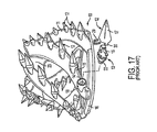
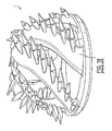
- Dredge cutterheads are used for excavating earthen material that is underwater, such as a riverbed. One example of a dredge cutterhead is illustrated in
Figure 17 . In general, a dredge cutterhead includeseveral arms 11 that extend forward from abase ring 16 to a hub 23. The arms are equally spaced about the base ring and formed with a broad spiral about the central axis of the cutterhead. Each arm is provided with a series of spaced apartteeth 12 to dig into the ground. - In use, the cutterhead is rotated about its central axis to excavate the earthen material. To excavate the desired swath of ground the cutterhead is moved side-to-side as well as forward. On account of swells and other movement of the water, the cutterhead will also tend to move up and down, and periodically impact the bottom surface. As a result of this unique cutting action, the teeth of a dredge cutterhead experience heavy transverse as well as axial loading and heavy impact jacking loads that thrust the tooth up, down and sideways. The heavy transverse loading of the tooth is further engendered by the operator's inability to see the ground that is being excavated underneath the water. Unlike other excavators (e.g., a front end loader), the operator of a dredge cutterhead cannot effectively guide the cutterhead along a path to best suit the terrain to be excavated.
- Due to the rotative digging action of the cutterhead, each tooth penetrates the ground on the order of 30 times a minute as compared to about 1 time a minute for mining teeth. As a result, the teeth experience a great amount of wear during use. It is desirable therefore for the teeth to be easily removed and installed to minimize downtime for the cutterhead. As is common with wear assemblies for excavating equipment, dredge teeth comprise a plurality of integrally connected parts so as to minimize the amount of material needing replacement, i.e., only the worn components need to be replaced.
- In the example of
Figure 17 , each tooth includes abase 18, anadapter 13, a point ortip 17, and alock 29. Thebase 18 is cast on thearm 11 at a particular location and orientation to maximize digging.Adapter 13 includes arear end 22 that is received in asocket 14 defined in the base, and a forwardly projectingnose 15 to hold thepoint 17. Aremovable lock 29 is provided to facilitate the required frequent replacement of thetooth points 17. The adapter is held in the socket by a large fillet weld about the circumference of therear end 22. In other knowndredge cutterheads 1, theadapter 2 is bifurcated to define a pair of legs that are configured to wrap about the arm 3 (Fig. 18 ). These adapters are welded directly to the arm without a base member. - Although the tooth points require the most frequent replacement in a dredge cutterhead, the adapters still wear and need periodic replacement. However, replacing even a single adapter on a dredge cutterhead is a long process. The welded adapter must first be cut off with a torch. Then, portions of the arm and base that were damaged by the removal of the adapter must be repaired and rebuilt. Finally, a new adapter is welded into place. This process typically entails 10-12 man-hours per adapter. Hence, a lengthy delay in a dredging operation is unavoidable even when replacing only a single adapter. Moreover, in view of this lengthy delay, an operator will often wait until several adapters need replacement to take the cutterhead out of operation. As a result, the actual delay in operation that usually results is longer. Indeed, with a typical cutterhead having 50-60 teeth a rebuilding process of the entire cutterhead could require more than 600 man-hours. In an effort to avoid substantial loss of dredging time, most dredging operations maintain three or four cutterheads so that the entire cutterhead can be exchanged when one or more adapter needs to be replaced, the cutterhead needs to be rebuilt, or if the cutterhead breaks. However, a cutterhead is expensive. The maintaining of extra cutterheads that are not used, but held only when the one in use is serviced is an undesirable use of resources.
- In one aspect of the present invention, the adapter is mechanically attached to the arm for easy installation and removal. The adapter is held to a base on the arm solely by a mechanical construction without the need for welding the adapter. In the preferred construction, the base and adapter are formed with complementary coupling configurations to prevent release of the adapter from the base except in a release direction. A removable lock is used to prevent undesired release of the adapter from the base in the release direction. With a mechanical attachment, the adapter can be easily replaced by simply removing the lock and moving the adapter in the release direction. There is no weld to be cut, no need to repair the base and arm, and no re-application of a weld. As opposed to 10-12 man-hours for replacing a welded adapter, a mechanically attached adapter in accordance with the present invention can be changed in as little as 10 minutes. This is a dramatic improvement which not only substantially reduces downtime for the cutterhead, but can also make the elimination of an entire spare cutterhead at the dredging site possible. As a result, instead of typically needing three or four cutterheads at a dredge site, only two or three may be needed.
- In a preferred construction of the present invention, the adapter includes a generally T-shaped slot that receives a complementarily-shaped tongue on the base, and an opening for receiving a lock. The lock, when inserted into the opening, opposes a wall of the base and a wall of the opening to prevent release of the tongue and slot, and thereby holds the adapter to the base.
- It is common for adapters of various excavators, such as a front end loader, to be mechanically attached to the excavating bucket. For example,
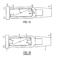
U.S. Patent No. 5,653,048 discloses an adapter with a T-shaped slot that receives a T-shaped boss welded to the lip of an excavating bucket. A lock is fit within an opening in the top of the adapter to prevent loss of the adapter from the lip. A bearing surface is formed at the front end of the boss to provide axial support for the adapter. While this construction well supports an adapter on an excavating bucket, it is not well suited for use on a dredge cutterhead. - In an excavating bucket, the teeth are primarily subjected to axial loading as the bucket is driven forward through the ground. However, as discussed above, the teeth on a dredge cutterhead are subjected to heavy and frequent transverse loads due to the manner in which the cutterhead is operated. In the noted '048 patent, the adapter 4 is slid onto the
boss 5 with a slight side clearance for ease of assembly. The application of a large side load L applied against thetooth point 6 tends to rotate the adapter about the received boss to the extent of the defined clearance between the parts (Fig. 16 ). This rotation of the adapter results in the generation of resistant forces R1-R4 and high stresses being generated through essentially "point" contacts in the corners of the assembly. Although true point contact is impossible, the term is used to identify large applications of force over a relatively small area. In particular, the application of large forces R2, R3 at "points" on the front of the base and thelock 7 place exceptionally high levels of stress on the components. Such high stress levels, in turn, cause greater wearing of the parts at these locations and a shortened usable life of the parts. The increased wearing also enlarges the clearance space, which can lead to rattling of the components during use. Such rattling of the parts further quickens wearing of the parts. - In ordinary digging, such as with a front end loader, fines become impacted between the adapter and base so that rattling is reduced or eliminated even when wearing has created large gaps between the parts. However, in a dredging operation, the water sweeps the fines in and out of the gaps, and prevents the build up of fines between the parts. Since the gaps between the parts would ordinarily remain in a dredging operation, an adapter mechanically attached to a boss on a dredge cutterhead by a known construction would continually rattle against the boss and repeatedly apply large loads in point contacts along the front and rear of the adapter. Moreover, since the fines are constantly swept into and out of the gaps between the parts with the water, the fines would actually function as a grinding compound on the parts to further exacerbate wearing of the parts. Consequently, adapters for dredging operations have not before been mechanically attached to the dredge cutterhead arms.
- However, these shortcomings are overcome in the present invention so that adapters in dredging teeth can be mechanically attached to the arms. In particular, the front of the base is curved and in contact with a complementary abutment of the adapter. As a result, when side loads push the adapter in a rotative manner, the arcuate shape of the bearing surfaces enables the surfaces to remain in substantially full flush contact with each other. This full contact arrangement as opposed to a point contact greatly reduces the stress otherwise experienced in the corners of the components. Rather than having high loads applied essentially as point contacts, the loads are spread over substantially the entire bearing surface to greatly minimize the stress in the parts and, in turn, substantially lengthen the usable life of the parts.
- In a preferred construction, the arcuate bearing surfaces define spherical segments to maintain substantially full contact between the bearing surfaces of the adapter and the base under both horizontal and vertical transverse loading. In addition, the rear bearing surface of the base and the front of the lock are also preferably formed with similar arcuate surfaces to likewise maintain substantially full contact between the lock and the base. Preferably, the radii of curvature for the bearing suface at the front and rear of the adapter originate from the same point.
- In another aspect of the invention, a wear member for use with excavators other than dredge cutterheads could also be benefited by incorporating the curved bearing surfaces described above for the adapter.
- In another aspect of the present invention, the lock is formed to tighten the connection between the base and adapter. A tightened assembly alleviates rattling and thereby lengthens the useful life of the tooth. The above-noted '048, patent discloses a lock with a threaded plug that tightens the adapter on the boss. Nevertheless, the stress and strains of digging can work to loosen even an initially tightened arrangement such that the adapter will still shift and rattle against the base resulting in increased wear, particularly with the high frequency of penetration and varied loading of teeth on a dredge cutterhead. Further, with a loosening assembly, there would be nothing in a water environment to prevent the components from rattling during use.
- Therefore, in accordance with another aspect of the present invention, the lock further includes a resilient element that cooperates with an actuator to maintain a tight engagement between the adapter and base even after loads have introduced wear between the parts. The resilient element is sandwiched between a pair of rigid members. The actuator initially pulls the adapter into a tight engagement with the base and draws the rigid members together to compress the resilient element. As looseness begins to develop in the assembly due to wearing, the resilient element expands to dampen any shifting or rattling of the adapter on the base and thereby maintain a tight engagement between the two components. The rigid members also preferably have at least one stop that prevents excessive compression of the resilient element. In this way, the rigid members initially form a rigid lock that is tightly set between the adapter and the base, and which also protect the internal resilient element from premature failure on account of being overloaded.
- As discussed above, the arms in a dredge cutterhead have a broad spiraling configuration. As a result, the teeth each project from the arm at a unique orientation to maximize digging. Since the teeth are mounted in different orientations on the arm, care must be taken to ensure that each adapter is properly positioned on the arm. This additional positioning procedure further lengthens the time needed to install new adapters in past cutterheads. In the example illustrated in
Figure 17 , a resin is poured into the socket to harden around the first mounted adapter to thus form a recess adapted to properly orient successive adapters for the dredging operation. Nevertheless, this design still requires a careful, time-consuming procedure to initially place the adapters properly on the arm as well as the extra work of pouring and curing the resin. - As can be appreciated, since there is no guiding base in the direct welding of adapters to the arms, such as in
Figure 18 , it is nearly impossible to properly position each of the adapters for maximum digging efficiency. Moreover, arms on a dredge cutter do not have a uniform configuration as they extend from the base ring to the hub. To avoid the cost and trouble of having to make a specifically shaped adapter to custom fit each designated location along the arm, the adapters are formed to have a general fit on the arm. As a result, the fit is typically loose, thus making it even more difficult to properly position the adapter for welding. Digging efficiency is therefore usually lost in the improper mounting of such teeth to a dredge cutter. - In another aspect of the present invention, the arm is formed with a plurality of spaced apart locator formations along the front edge of the arm to properly position the teeth at the desired orientations. The locator formations each have the same structural configuration, although their orientations relative to the surrounding arm contour may differ so as to properly orient each tooth for the particular location along the arm. In one aspect of the invention, a separable base member is provided with a complementary coupling formation to matingly fit with the locator formations so as to support and position the adapter properly on the arm. As a result, each base can be formed with the same shape irrespective of where along the arm it is to be mounted. Moreover, these bases are adapted to be positioned on the dredge cutterhead in an easy, accurate and quick manner. In an alternative embodiment of the invention, a weld-on adapter includes a coupling formation to match the locator formations provided on the arm so that weld-on adapters can be easily secured in proper position on the arms. As with the bases of the invention, these adapters can each be made to have-the same shape and easily positioned correctly irrespective of where along the arm they are to be mounted.
-
-
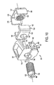
Figure 1 is a front perspective exploded view of an attachment assembly in accordance with the present invention. -
Figure 2 is a perspective view of a base in accordance with the present invention in conjunction with an imaginary sphere. -
Figure 3 is a top plan view of the base. -
Figure 4 is a side elevational view of the base. -
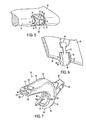
Figure 5 is a perspective view of a portion of an arm of a dredge cutterhead in accordance with the present invention. -
Figure 6 is a top perspective view of the base positioned on the arm. -
Figure 7 is a rear perspective view of an adapter in accordance with the present invention. -
Figure 8 is a side elevational view of the adapter. -
Figure 9 is a top plan view of the adapter. -
Figure 10 is an exploded perspective view of a lock in accordance with the present invention. -
Figure 11 is a side elevational view of the lock. -
Figure 12 is a top plan view of the lock. -
Figure 13 is a perspective view of the lock. -
Figure 14 is a cross-sectional view of the lock taken along line XIV-XIV inFigure 13 . -
Figure 15 is a top schematic view of a tooth in accordance with the present invention under side loading. -
Figure 16 is a top schematic view of a prior art tooth under side loading. -
Figure 17 is a perspective view of a prior art dredge cutterhead. -
Figure 18 is a perspective view of another prior art dredge cutterhead. -
Figure 19 is a perspective view of a weld-on adapter mounted on a dredge arm in another embodiment. -
Figure 20 is a side view of an alternative weld-on adapter. - The present invention pertains to an assembly for securing a wear member to an excavator. The present invention is particularly suited for mounting a tooth on a dredge cutterhead because of the ability of the tooth in the preferred construction to better withstand heavy transverse loading typical of a dredging operation and dampen rattling of the parts. Nevertheless, a tooth in accordance with the present invention could be used with other excavators. Additionally, other wear members used in excavating equipment (e.g., shrouds) could be mounted using the present invention.
- In accordance with the present invention, a
tooth 30 includes a base or mount 32, anadapter 34, a point (not shown), and a lock 36 (Fig. 1 ). The tooth components will at times be described in relative terms, such as up and down, even though the operation of the dredging equipment will cause the teeth to assume many different orientations. These directions are used for explanation purposes only and should ordinarily be understood with respect to the orientation inFigure 1 . - In the preferred construction,
base 32 has alower leg 38, afront body 40 and anupper leg 42 in a generally U-shaped configuration (Figs.1-4 ) that wraps around thefront edge 44 of anarm 48 of a cutterhead for enhanced support. The base is preferably a cast one-piece product that is fixed to the arm by welding, but could be mechanically attached or constructed as a multi-piece component. Alternatively, the base could be fixed to the arm as a structure that is cast as a unitary part of the arm (not shown). -
Lower leg 38 extends only a short distance along alower side 47 ofarm 48, although it may be omitted or provided with an extended construction.Upper leg 42 extends rearward along anupper side 55 ofarm 48 and includes acoupling configuration 56 for securing the adapter. Since the lower orinner side 47 of an arm of a dredge cutterhead is more difficult to access, the coupling configuration is preferably formed to be on the upper orouter side 55 of the arm. Nevertheless, alternative constructions are possible. For instance, the legs could be reversed on the arm or a coupling configuration could be provided on both of the upper and lower sides of the arms. Thelegs body 40 collectively define aninner surface 54 that faces the arm. To facilitate effective welding of the base to the arm, theinner surface 54 is shaped to substantially conform to the contour of the portion ofarm 48 it opposes. The base is welded to the arm along substantially its entire perimeter to securely fix the base to the cutterhead. -
Upper leg 42 extends rearward ofbody 40 alongupper side 55 of the arm to definecoupling configuration 56 for securing the adapter. The coupling configuration is preferably an axial T-shapedtongue 57 that slidably engages acomplementary construction 58 onadapter 34. Nonetheless, other constructions provided with at least one laterally extending shoulder could be used to couple the adapter and the base. As examples, thecoupling configuration 56 could be formed as other generally T-shaped tongues such as a dovetail tongue and other tongues that laterally broaden in a symmetrical manner, other non-symmetrical shaped tongues, or a slot having T, dovetail or other shape. In any event, the upper leg preferably extends initially upward abovebody 40 to enable the adapter to slide past the body and couple with the tongue. The rear end wall ofupper leg 42 defines arear bearing surface 60 adapted to engagelock 36. As discussed more fully below, the rear bearing surface is preferably curved and most preferably defines a convex spherical segment (Fig. 2 ). Nonetheless, a flat rear bearing surface could be used, albeit with reduced benefits. - The
body 40 projects forward from thefront edge 44 ofarm 48 to resist the forces applied to thetooth 30 during use. In the preferred construction, the body includessidewalls bottom walls front bearing surface 68. Thefront bearing surface 68 has a convex, curved shape, as discussed more fully below, to maintain a substantially full face contact with a complementary surface on the adapter during transverse loading of the tooth. In the preferred construction,front bearing surface 68 defines a convex spherical segment (as illustrated by the shaded portion inFigure 2 ) to accommodate transverse loading in any direction, such as, side loads, upward loads, downward loads or virtually any load that applies a force transverse to thelongitudinal axis 69 of the tooth. Nevertheless, bearingsurface 68 could be formed with a surface that is curved in both horizontal and vertical directions but is not spherical. In this type of construction the radii of curvature for either or both curved directions could be fixed or variable. Moreover, the bearingsurface 68 could be provided with a curved shape in only one direction, although with reduced benefits. For instance, bearingsurface 68 could be curved in only a horizontal or vertical direction or in any particular desired direction. However, when curved in only one direction, the desired full face contact can only be maintained for transverse loading in the same general direction as the curvature of the bearing surface. - The radius (or radii) of curvature defining bearing
surface 68 is based upon the relative gap that exists between the base and the adapter. For instance, a clearance is formed between the parts to ensure the adapter can be coupled to the base, especially along the coupling configuration. When a lateral load is applied to the tooth tip, the adapter will rotate until the gaps along the sides close at diagonally opposing corners forming a couple to oppose the lateral load. If the gap between the base and the adapter is the same along the front end and the rear end ofbase 32, then the center of rotation of the adapter will be at about the mid point M of base 32 (i.e., the mid point between bearingsurfaces 60, 68). However, if the gap is smaller at one end as compared to the other end, then the center of rotation will be closer to the end with the smaller gap depending on the amount of the disparity between the parts, i.e., the greater the disparity in the gaps, the greater the center of rotation shifts toward the end with the smaller gap. In the preferred construction, the center of rotation is used as the imaginary center point for the radius of curvature. As can be appreciated, the differences in the clearance along the sides could be different than the clearance along the top and bottom of the base and adapter. In this construction, the curvature in the horizontal direction is preferably different than the curvature in the vertical direction so as to correspond to the spacing of the different clearances. - In the preferred construction, as shown in
Fig. 2 , therear bearing surface 60 is curved in the same way asfront bearing surface 68, although they could be different. Accordingly, the rear bearing surface can be varied in the same manner as discussed above for front bearing face 68 (e.g., with curves in one or more directions). Preferably, the rear and front bearing surfaces 60, 68 are defined by radii of curvature that initiate from the same point that matches the center of rotation of the adapter. However, due to unavoidable deflection of the parts under heavy loads, there can be some divergence of the points defining the radii of curvature for the front and rear bearing surfaces. Further,rear bearing surface 60 can have a widely different starting point for defining the radius of curvature, or it can even be flat, though such a construction will impose higher stresses on the lock and rear of the base. Hence, the front and rear bearing surfaces may have the same curvature, but also may simply have corresponding curvatures, i.e., where the radius of curvature originates at the same point even though they may each have different lengths. For example, if the center of rotation of the adapter, as discussed above, is closer to the rear end than the front end, then rear bearingsurface 60 will preferably have a smaller radius of curvature than front bearingsurface 68. - The
front edge 44 ofarm 48 is preferably provided with a plurality of spaced apartlocator formations 65 for mounting the excavating teeth. In a preferred embodiment, each locator formation includes a locator nose 70 (Fig. 5 ) that projects from arecess 71. In the preferred construction, each locator nose is cast as part of the arm with a particular shaped core in the mold. The core is placed in the mold in the orientation needed for positioning each tooth properly on the arm. In this way, there are no difficulties in positioning the adapters on the arms. Thelocator noses 70 cast in thearm 48 already provides the desired orientation for the tooth. - In the preferred construction, the locator nose projects from a
recess 71 formed in the front edge ofarm 48. The trough surfaces 72 in the bottom of the recesses oppose theinner edges 53, 54 of thesidewalls outer surfaces 74, 75 ofsidewalls coupling formation 78 that interacts with thelocator formations 65 to properly position the excavating tooth for maximum cutting efficiency. In this construction, thebody 40 ofbase 32 defines apocket 77 that matingly receives thelocator nose 70 to properly position and support the base on the arm. The side faces 79 andfree end face 80 ofnose 70 fit against complementarysurfaces defining pocket 77 to properly orient the tooth on the arm and provide support for the boss in addition to the welds. For this reason,noses 70 preferably have a considerable forward extension. In a preferred construction, the noses extend approximately 1.50 inches beyond trough surfaces 72 and within a range of about 75 to 2.25 inches. Nevertheless, lesser or greater nose extensions could be used. - The wear member in the form of adapter 34 (
Figs. 1 and7-9 ) has arear portion 86 that mounts to base 32 and afront portion 88 for holding a point or tip (not shown). In the preferred construction, the front portion includes a forwardly projectingnose 90 that is received into the socket of a point. The nose can have any configuration for mounting a point. In this embodiment, the front portion further includes aslot 92 for receiving a lock pin (not shown) to hold the point to the adapter. Therear portion 86 includes anupper leg 94, alower leg 96, and amid portion 98.Lower leg 96 ofadapter 34 overliesbottom wall 66. Therear end 97 ofleg 96 opposesfront wall 101 of the base so that under extreme loads wall 101 functions to stop the shifting of the adapter on the base.Upper leg 94 extends rearward to overlietop wall 64 andupper leg 42 ofbase 32. The upper leg ofadapter 34 includes acoupling configuration 58 that is adapted to mate with thecoupling configuration 56 ofbase 32. Hence, the coupling configuration ofadapter 34 can be varied in the same way as the coupling configuration forbase 32. In the preferred construction,upper leg 94 includes a T-shapedslot 103 that matingly receives T-shapedtongue 57. The T-shapedslot 103 is open along theinner surface 104 and in therear wall 106 ofupper leg 94 to facilitate receipt oftongue 57.Ribs 107 are preferably formed along theinner edge 108 ofmid portion 98 for enhanced strength to resist cracking during use (Figs. 1 ,7 and8 ). - The
mid portion 98 ofadapter 34 includes aninterior recess 109 having an abutment or abuttingsurface 105 adapted to abutfront bearing surface 68 ofbase 32.Abutment 105 is arcuate and concave in shape to match the arcuatefront bearing surface 68. Accordingly,abutment 105 and bearingsurface 68 each preferably define a spherical segment with essentially the same radius of curvature, although the curves could differ within a certain range of values primarily because of deflection that occurs in the parts under heavy loading. As discussed above, the preferred shape ofabutment 105 and bearingsurface 68 is defined by a radius of curvature that is determined by the clearance between the front and rear end portions of the adapter and base. In the most preferred configuration, the gaps between the base and the adapter are uniform from front to back along the sides and along the top and bottom so that the curved bearing surfaces 68, 105 each define a spherical segment. The actual desired size of the radius of curvature defining the spherical segments would depend on the gaps as well as the actual size of the part. As a general rule, the radius ofcurvature defining surfaces - As seen in
Figure 15 , a side load L1 tends to rotateadapter 34 relative to base 32 about a center of rotation C. The radius of curvature defining bearing surfaces 68, 105 originate from the same center of rotation. Because of the mating arcuate configuration ofabutment 105 and bearingsurface 68, these surfaces remain in essentially full bearing contact with each other. Accordingly, no forces are applied as point contacts in the axial direction to prematurely wear the parts. Instead, the axial loads are spread out over substantially the whole of theabutment 105 and bearingsurface 68 to greatly reduce the stress in the parts. As a result, the high stresses accompanying resultant forces R2, R3 (Fig. 16 ) are essentially eliminated. -
Adapter 34 further includes anopening 110 in a rear portion of upper leg 94 (Figs. 1 and7-9 ). In the preferred construction,opening 110 has a generally rectangular configuration with a curvedfront wall 113 and a curvedrear wall 115. Nevertheless, it is not necessary that the walls be curved or that the opening has an overall generally rectangular configuration. Rather, the opening can have virtually any shape so long as it receives the lock which, in turn, secures the adapter to the base. If there is any shifting ofadapter 34 during use, thelock 36 tends to move with the adapter. Hence, there is ordinarily no significant shifting between the lock and the adapter and thus no undue wearing therebetween.Rear wall 115 preferably includes ahole 117 that extends through therear end 106 ofupper leg 94 to accommodate an adjustment assembly oflock 36. Nevertheless,hole 117 could have a variety of different shapes or be eliminated if an adjustment assembly is not used or one is used that does not require the space provided byhole 117. -
Lock 36 is adapted to be received in opening 110 (Figs. 1 and10-14 ). In the preferred construction,lock 36 has a generally rectangular configuration with a curvedfront wall 123 and a curvedrear wall 125 to match the configuration ofopening 110. Although shifting between the adapter and lock is not likely, thecurved walls - In the preferred construction,
lock 36 comprises anouter part 127, aninner part 129, aresilient member 131 and an actuator, preferably in the form of ascrew 133.Outer part 127 defines acavity 134 for receiving theinner part 129 andresilient member 131. In general,outer part 127 is generally C-shaped to include abase wall 135, atop wall 137 and abottom wall 139. A pair oflips bottom walls inner part 129 andresilient member 131 incavity 134.Base wall 135 includes anaperture 136 for receivingscrew 133. The inner part also has a generally C-shaped configuration with acenter wall 147 and twosidewalls 149. The two C-shaped components fit together to generally define a box-like shape. In the preferred curved construction, sidewalls 149 are at obtuse angles to centerwall 147 to match the side edges 150 ofouter part 127. An internally threadedboss 151 extends rearward from the center ofcenter wall 147 to receivescrew 133.Resilient member 131 is preferably an elastomer. In the preferred construction, the elastomer is composed of neoprene or rubber, although other types of elastomeric materials can be used. The elastomer is shaped for receipt ininner part 129 aboutboss 151. In the preferred embodiment,resilient member 131 has abase portion 132 with anaperture 138 and a pair ofarm portions 142. Nevertheless, other shapes could be used. Moreover, other kinds of resilient members could be used, such as Beliville springs or a coiled spring. - The lock is assembled by placing the
resilient member 131 aboutboss 151 ininner part 129. The combined inner part and resilient member are then inserted laterally into the side ofcavity 134 inouter part 127, i.e., by side edges 150. Onceboss 151 is aligned withaperture 136,screw 133 is preferably back threaded intoboss 151 until it is received intoaperture 136. The screw ensures that the component parts do not become inadvertently disassembled. - In use, lock 36 is inserted into
opening 110 afteradapter 34 is placed overbase 32 withtongue 57 received in slot 103 (Fig. 1 ).Screw 133 includes ahead 153 with some means for engaging a tool (not shown) for turning the screw. In the preferred embodiment,screw head 153 hasinternal flats 155 for receiving an appropriate wrench. The free end ofscrew 133 includes abearing surface 157 that abutsrear bearing surface 60 when the screw is advanced. - Further advancement of
screw 133 against rear bearingsurface 60 causes therear face 125 ofbase wall 135 to push rearwardly against therear wall 115 ofopening 110. This expansion of the lock results inabutment 105 ofadapter 34 being brought into tight abutting relationship withfront bearing surface 68 ofbase 32. Further advancement ofscrew 133 following such abutment will then cause theinner part 129 to move toward theouter part 127 to compressresilient member 131 untilsidewalls 149abut base wall 135. The sidewalls will abutbase wall 135 to prevent over-compression of the resilient member. If the elastomer is a non-compressible rubber material or the like, there is enough open space between the inner and outer parts to permit theinner part 129 to be drawn against theouter part 127. Depending on the resistance in coupling the adapter to the base, the resilient member may compress in some instances before the adapter is fully tightened onto the base. In any event, withinner part 129 in abutting contact withouter part 127, lock 36 initially is a rigid lock member. As wear begins to develop betweenadapter 34 andbase 32,resilient member 131 expands to dampen movement of the adapter relative to the base and maintain a tight relationship between the components of the tooth. This expansion oflock 36 continues to hold the components tightly together untilresilient member 131 reaches its fully expanded position (i.e., when the inner part abuts against lips 141,143). -
Bearing surface 157 onscrew 133 preferably has a concave, arcuate surface to engage the corresponding rear bearing surface 60 (Fig. 14 ). In the most preferred construction, bearingsurface surface 157 remains in substantially full contact withrear bearing surface 60 asadapter 34 shifts under transverse loading (i.e., as the adapter rotates about its center of rotation). While bearing surfaces 60 and 157 can be formed with the same radius of curvature, bearingsurface 157 ofscrew 133 can alternatively be formed with a smaller radius of curvature so as to contactrear bearing surface 60 with a circular contact. The spherical configuration of the rear base surface still enables the circle contact ofscrew 133 to remain in substantially full contact withbase 32 during any shifting of the adapter. - Alternatively, other locks could be used so long as they abut
adapter 34 andbase 32 so as to prevent the adapter from sliding forwardly off of the base. For example, a lock with a different adjustment assembly could be used, such as the fluid actuator as disclosed inU.S. Patent No. 5,653,048 to Jones et al. , herein incorporated by reference. Similarly, an opening and lock such as disclosed inU.S. Patent No. 5,088,214 to Jones et al. , herein incorporated by reference, without an adjustment assembly could also be used. - In an alternative construction, weld-on
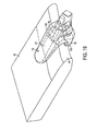
adapters 175 can be mounted on thelocator formations 65 of the dredgecutterhead arm 48 without bases 32 (Figure 19 ). While the use of such adapters does not provide the easy removal and installation procedures of the mechanically attached adapters discussed above, the locator formations still provide easy positioning of the adapters as well as additional support. In a preferred construction,adapters 175 include a pair ofbifurcated legs 177, 178 that straddle the arm, although a single leg could be used (not shown). If a single leg is used, the leg will preferably be located on the upper side of the arm to enable easier welding of the adapter to the arm. The adapter includes acoupling formation 180 to matingly fit with thelocator formations 65 so as to properly position the adapter, and thus, the tooth point (not shown) for maximum digging efficiency. As withbase 32,adapters 175 include apocket 183 that matingly receivesnose 70 with surfaces that oppose side faces 79 and end face 80 to properly position and support the adapter in use. The adapter is then welded along all or parts of its periphery. Also, as withboss 32, the adapter is preferably spaced from the trough surfaces 72 for easier removal of the adapter from the arm. - In another alternative construction,
adapter 175a includes a coupling formation 180a that does not rely uponnose 70 for positioning and support (Figure 20 ). In this arrangement, each locator formation includes a pair of spaced apart surfaces having a particular shape and spacing to engage, support and properly position a wear member. For example, trough surfaces 72 to each side ofnose 70 are formed with a shape that matches the inner edge surfaces of thebight 185a interconnectinglegs 177a, 178a. Thebight surface 185a, then, sets against trough surfaces to properly orient the tooth. An adapter with coupling formation 180a can include anenlarged pocket 183a that does not engagenose 70 or can be used with an arm that does not include anose 70. - In another alternative construction, another weld-on adapter can be fit over
base 32. In this construction, the adapter includes a pocket that matingly receivesbody 40 and includes a configuration, such as a recess, that enables the arm to fit over but not connect to the tongue ofbase 32. Alternatively, a base without a leg or with a leg having no coupling tongue could be used with such a weld-on adapter. In either case, thebody 40 ofbase 32 properly orients and provides support to the adapter, which is then welded to the arm. - The above-discussion concerns the preferred embodiments of the present invention. Various other embodiments as well as many changes and alterations may be made without departing from the spirit and broader aspects of the invention as defined in the claims.
- The paragraphs that follow define further embodiments that form part of the present disclosure.
-
Paragraph 1. An assembly for mounting a wear member to excavating equipment comprising: - a base adapted to be fixed to a digging portion of an excavator, the base including a first coupling configuration, a convex front bearing surface curved across substantially the entire front bearing surface, and a rear bearing surface;
- a wear member including a second coupling configuration that fits with the first coupling configuration to prevent release of the wear member except in a release direction, a concave abutting surface curved across substantially the entire abutting surface to abut the front bearing surface, an opening having a bearing wall, and a forwardly projecting working portion; and
- a lock received into the opening to oppose the rear bearing surface and the bearing wall of the opening to prevent release of the coupling configurations in the release direction and thereby hold the wear member to the base.
-
Paragraph 2. An assembly in accordance withparagraph 1 in which the front bearing surface and the abutting surface are each mutually curved at substantially the same radius of curvature. -
Paragraph 3. An assembly in accordance withparagraph 2 in which the front bearing surface and the abutting surface are each curved in two perpendicular directions. - Paragraph 4. An assembly in accordance with
paragraph 3 in which the front bearing surface and the abutting surface each define a spherical segment. -
Paragraph 5. An assembly in accordance with paragraph 4 in which the contact surface and the rear bearing surface have substantially the same radius of curvature. -
Paragraph 6. An assembly in accordance withparagraph 5 in which the lock includes a contact surface in engagement with the rear bearing surface, and the contact surface and the rear bearing surface each define a spherical segment. -
Paragraph 7. An assembly in accordance withparagraph 6 in which the radius of curvature for the front bearing surface and for the rear bearing surface originate from the substantially same point. - Paragraph 8. An assembly in accordance with
paragraph 1 in which the front bearing surface and the abutting surface are each curved in two perpendicular directions. - Paragraph 9. An assembly in accordance with
paragraph 1 in which the front and rear bearing surfaces are each curved in two perpendicular directions. -
Paragraph 10. An assembly in accordance with paragraph 9 in which the front and rear bearing surfaces are each defined by a radius of curvature in each of the two perpendicular directions. -
Paragraph 11. An assembly in accordance withparagraph 10 in which the radii of curvature for the front and rear bearing surfaces defining the curves in a one of the directions originate from the same point. -
Paragraph 12. An assembly in accordance withparagraph 11 in which the radii of curvature for the front and rear bearing surfaces defining the curves in the other of the directions originate from the same point. -
Paragraph 13. An assembly in accordance withparagraph 1 in which the lock includes a contact surface in engagement with the rear bearing surface, and the contact surface and the rear bearing surface are each curved. -
Paragraph 14. An assembly in accordance withparagraph 13 in which the contact surface and the rear bearing surface have substantially the same radius of curvature. -
Paragraph 15. An assembly in accordance withparagraph 13 in which the contact surface and the rear bearing surface are each curved in two perpendicular directions. -
Paragraph 16. An assembly in accordance withparagraph 15 in which the contact surface and the rear bearing surface each define a spherical segment. -
Paragraph 17. An assembly in accordance withparagraph 1 wherein the rear bearing surface is curved, the front and rear bearing surfaces are each defined by a radius of curvature, and the radii of curvature for the front and rear bearing surfaces have the same origination point. -
Paragraph 18. An assembly in accordance withparagraph 17 in which the front and rear bearing surfaces each define a spherical segment. - Paragraph 19. An assembly in accordance with
paragraph 1 in which one of the first and second coupling configurations is a tongue with at least one lateral shoulder and the other one of the first and second coupling configurations is a slot to matingly receiving the tongue. - Paragraph 20. An assembly in accordance with paragraph 19 in which the first coupling configuration is the T-shaped tongue and the second coupling configuration is the T-shaped slot.
- Paragraph 21. An assembly in accordance with
paragraph 1 in which the first coupling configuration is a tongue and the second coupling configuration is a slot. -
Paragraph 22. An assembly in accordance withparagraph 1 in which the lock includes a first contact surface that opposes the bearing wall and a second contact surface that opposes the rear bearing surface, wherein the lock further includes an acttiator that selectively moves the first and second contact surfaces away from each other to tighten the engagement of the wear member on the base. - Paragraph 23. An assembly in accordance with
paragraph 22 in which the actuator includes a screw, the free end of which defines one of the first and second contact surfaces. - Paragraph 24. An assembly in accordance with paragraph 23 in which the free end of the screw defines the second contact surface.
- Paragraph 25. An assembly in accordance with
paragraph 22 in which the second contact surface and the rear bearing surface are each curved. - Paragraph 26. An assembly in accordance with paragraph 25 in which the second contact surface and the rear bearing surface each define a spherical segment.
- Paragraph 27. An assembly in accordance with
paragraph 22 in which the lock includes a front member, a rear member and a resilient member therebetween, wherein the actuator is adapted to compress the resilient member between the front and rear members when the lock is in the opening such that the resilient member can tighten the wear member on the base as wear occurs between the wear member and the base. - Paragraph 28. An assembly in accordance with paragraph 27 in which the actuator is a screw.
-
Paragraph 29. An assembly in accordance with paragraph 28 in which the resilient member is an elastomer. -
Paragraph 30. An assembly in accordance with paragraph 27 in which the resilient member is an elastomer. - Paragraph 31. An assembly in accordance with paragraph 27 wherein the lock further includes at least one stop for limiting the compression of the resilient member.
-
Paragraph 32. An assembly in accordance withparagraph 1 in which the lock includes an actuator and a resilient member, wherein the actuator compresses the resilient member and the resilient member expands the lock to tighten the engagement of the wear member on the base. - Paragraph 33. An assembly in accordance with
paragraph 1 wherein the base is cast as a unitary portion with an arm of a dredge cutterhead. -
Paragraph 34. An assembly for mounting a wear member to excavating equipment comprising: - a base adapted to be fixed to a digging portion of an excavator, the base including a first coupling configuration, a front bearing surface, and a rear bearing surface;
- a wear member including a second coupling configuration that fits with the first coupling configuration to prevent release of the wear member except in a release direction, an abutting surface to abut the front bearing surface, an opening having a bearing wall, and a forwardly projecting working portion; and
- a lock received into the opening to oppose the rear bearing surface and the bearing wall of the opening to prevent release of the coupling configurations in the release direction and thereby hold the wear member to the base, the lock including an actuator and a resilient member, wherein when the lock is in the opening the actuator is operable to draw the wear member on the base into a tighter fit and to compresses the resilient member, and wherein the resilient member expands the lock to tighten the engagement of the wear member on the base as wear develops in the assembly.
- Paragraph 35. An assembly in accordance with
paragraph 34 in which the lock includes a first contact surface that opposes the bearing wall and a second contact surface that opposes the rear bearing surface, wherein the lock further includes an actuator that selectively moves the first and second contact surfaces away from each other to tighten the engagement of the wear member on the base. -
Paragraph 36. An assembly in accordance with paragraph 35 in which the actuator includes a screw, the free end of which defines one of the first and second contact surfaces. - Paragraph 37. An assembly in accordance with
paragraph 36 in which the free end of the screw defines the second contact surface. -
Paragraph 38. An assembly in accordance with paragraph 35 in which the second contact surface and the rear bearing surface are each curved. - Paragraph 39. An assembly in accordance with
paragraph 38 in which the second contact surface and the rear bearing surface each define a spherical segment. -
Paragraph 40. An assembly in accordance withparagraph 34 in which the lock includes a front member, a rear member and a resilient member therebetween, wherein the actuator is adapted to compress the resilient member between the front and rear members when the lock is in the opening such that the resilient member can tighten the wear member on the base as wear occurs between the wear member and the base. - Paragraph 41. An assembly in accordance with
paragraph 40 in which the actuator is a screw. -
Paragraph 42. An assembly in accordance with paragraph 41 in which the resilient member is an elastomer. - Paragraph 43. An assembly in accordance with
paragraph 40 in which the resilient member is an elastomer. -
Paragraph 44. An assembly in accordance withparagraph 40 wherein the lock further includes at least one stop for limiting the compression of the resilient member. - Paragraph 45. An assembly in accordance with
paragraph 34 wherein the base is cast as a unitary portion of the excavator. -
Paragraph 46. A wear member for attachment to an excavator on which is fixed a base, the wear member comprising a leg defining a coupling configuration having at least one lateral shoulder for receiving a complementary shaped tongue on the base, an opening for receiving a lock, a forwardly projecting working portion, and a rearwardly facing abutting surface adapted to abut a bearing surface of the base, the abutting surface defining a concave curved segment across substantially the entire abutting surface. -
Paragraph 47. A wear member in accordance withparagraph 46 in which the abutting surface is curved in two perpendicular directions. -
Paragraph 48. A wear member in accordance withparagraph 46 in which the abutting surface is curved in a direction generally parallel with a width of the rear leg. - Paragraph 49. A wear member in accordance with
paragraph 46 in which the abutting surface is curved in a direction generally perpendicular to a width of the rear leg. -
Paragraph 50. A wear member in accordance withparagraph 46 wherein the abutting surface defines a spherical segment. - Paragraph 51. A wear member in accordance with
paragraph 46 in which the opening includes a transverse segment and an axial segment that opens in a rear wall of the wear member. -
Paragraph 52. A wear member in accordance withparagraph 46 in which the opening has a rear wall with a curved configuration. - Paragraph 53. A wear member in accordance with
paragraph 46 in which the wear member is an adapter for mounting a tooth point and the coupling configuration is a slot with at least one lateral shoulder. -
Paragraph 54. A wear member for attachment to an excavator on which is fixed a base, the wear member comprising a leg defining a coupling configuration having at least one lateral shoulder for receiving a complementary shaped tongue on the base, an opening for receiving a lock, a forwardly projecting working portion, and a rearwardly facing concave abutting surface adapted to abut a bearing surface of the base, wherein the abutting surface is curved in two perpendicular directions. -
Paragraph 55. A wear member in accordance withparagraph 54 wherein the abutting surface defines a spherical segment. -
Paragraph 56. A wear member in accordance withparagraph 54 in which the opening includes a transverse segment and an axial segment that opens in a rear wall of the wear member. -
Paragraph 57. A wear member in accordance withparagraph 54 in which the opening has a rear wall with a curved configuration. -
Paragraph 58. A wear member in accordance withparagraph 54 in which the wear member is an adapter for mounting a tooth point and the coupling configuration is a slot with at least one lateral shoulder. - Paragraph 59. A base adapted to be fixed to a digging edge of an excavator for mounting a wear member, the base having a generally U-shaped configuration for wrapping around the front edge of the front bearing surface and comprising a leg including a coupling configuration having a laterally extending shoulder for receiving and holding a wear member, and a body, the body having a convex front bearing surface curved across substantially the entire front bearing surface for abutting a complementary surface of the wear member, and a rear bearing surface that faces rearward for abutting a lock.
-
Paragraph 60. A base in accordance with paragraph 59 in which the bearing surface is curved in two perpendicular directions. - Paragraph 61. A base in accordance with paragraph 59 in which the bearing surface is curved in a direction generally parallel with a width of the first leg.
- Paragraph 62. A base in accordance with paragraph 59 in which the bearing surface is curved in a direction generally perpendicular to a width of the first leg.
- Paragraph 63. A base in accordance with paragraph 59 wherein the bearing surface defines a spherical segment.
-
Paragraph 64. A base in accordance with paragraph 59 in which a radius of curvature for the front bearing surface and for the rear bearing surface originate from a substantially same point. -
Paragraph 65. A base in accordance with paragraph 59 in which the coupling configuration is the T-shaped tongue. -
Paragraph 66. A base in accordance with paragraph 59 wherein the front bearing surface defines a convex spherical segment. - Paragraph 67. A base in accordance with paragraph 59 wherein the rear bearing surface is curved.
-
Paragraph 68. A base in accordance with paragraph 59 wherein the front and rear bearings surfaces each have a convex curvature. -
Paragraph 69. A base in accordance with paragraph 59 wherein the front and rear bearing surfaces each define a spherical segment wherein the radius of curvature defining each of the bearing surfaces has the same origination point. -
Paragraph 70. A base adapted to be fixed to a digging edge of an excavator for mounting a wear member, the base including a coupling configuration having a laterally extending shoulder for receiving and holding a wear member, a body having a convex front bearing surface for abutting a complementary surface of the wear member, and a convex rear bearing surface that faces rearward for abutting a lock. -
Paragraph 71. A base in accordance withparagraph 70 in which a radius of curvature for the front bearing surface and for the rear bearing surface originate from a substantially same point. -
Paragraph 72. A lock adapted to secure a wear member to a base, the wear member having an opening for receiving the lock, the lock comprising a front member, a rear member, a resilient member between the front and rear members, and an actuator, the rear member including a rear surface to abut a rear wall of the opening in the adapter, the actuator including a front surface to abut a rear bearing surface of the base, the actuator being operable to move the front surface and the rear surface away from each other to tighten the connection of the adapter and the boss, and the actuator being further operable to draw the front and rear members together to compress the resilient member. - Paragraph 73. A lock in accordance with
paragraph 72 in which the actuator is a screw. -
Paragraph 74. A lock in accordance with paragraph 73 in which the screw is threadedly connected to the front member. - Paragraph 75. A lock in accordance with
paragraph 72 in which the front surface defines a concave curved surface. -
Paragraph 76. A lock in accordance with paragraph 75 in which the front surface defines a spherical segment. -
Paragraph 77. A lock in accordance withparagraph 72 in which the resilient member is an elastomer. -
Paragraph 78. A dredge cutterhead comprising: - a plurality of spiraling arms extending about a common axis; and
- a plurality of teeth attached to each arm, each tooth including:
- a base fixed to one of the arms, the base including a first coupling configuration, a convex front bearing surface that is curved, and a rear bearing surface;
- an adapter including a second coupling configuration, the first and second coupling configurations being coupled together, a curved concave abutting surface in abutment with the front bearing surface, and an opening having a bearing wall; and
- a lock received into the opening to oppose the rear bearing surface and the rear wall of the opening to prevent release of the coupling configurations and thereby hold the adapter to the base.
-
Paragraph 79. A dredge cutterhead in accordance withparagraph 78 in which the front bearing surface and the abutting surface are each mutually curved at a same radius of curvature. -
Paragraph 80. A dredge cutterhead in accordance withparagraph 78 in which the front bearing surface and the abutting surface each define a spherical segment. - Paragraph 81. A dredge cutterhead in accordance with
paragraph 78 in which the lock includes a contact surface in engagement with the rear bearing surface, and the contact surface and the rear bearing surface each define a spherical segment. -
Paragraph 82. A dredge cutterhead in accordance withparagraph 78 in which the contact surface and the rear bearing surface have a same radius of curvature about a same origination point. - Paragraph 83. A dredge cutterhead in accordance with
paragraph 78 in which the lock includes a contact surface in engagement with the rear bearing surface, and the contact surface and the rear bearing surface are each curved. -
Paragraph 84. A dredge cutterhead in accordance withparagraph 78 in which one of the first and second coupling configurations is a T-shaped tongue and the other one of the first and second coupling configurations is a mating T-shaped slot. - Paragraph 85. A dredge cutterhead in accordance with
paragraph 78 in which the lock includes a first contact surface that opposes the rear wall and a second contact surface that opposes the rear bearing surface, wherein the lock further includes an actuator that selectively moves the first and second contact surfaces away from each other to tighten the engagement of the adapter on the base. -
Paragraph 86. A dredge cutterhead in accordance with paragraph 85 in which the actuator includes a screw the free end of which defines one of the first and second contact surfaces. - Paragraph 87. A dredge cutterhead in accordance with
paragraph 86 in which the second contact surface and the rear bearing surface are each curved and abutted against each other. -
Paragraph 88. A dredge cutterhead in accordance with paragraph 87 in which the second contact surface and the rear bearing surface each define a spherical segment. - Paragraph 89. A dredge cutterhead in accordance with paragraph 85 in which the lock includes a front member, a rear member and a resilient member therebetween, wherein the actuator is adapted to compress the resilient member between the front and rear members when the lock is in the opening such that the resilient member can tighten the adapter on the base as wear occurs between the adapter and the base.
-
Paragraph 90. A dredge cutterhead in accordance with paragraph 89 in which the actuator is a screw. - Paragraph 91. A dredge cutterhead in accordance with
paragraph 90 in which the resilient member is an elastomer. -
Paragraph 92. A dredge cutterhead in accordance withparagraph 78 wherein each base is cast as a unitary portion of the respective arm. - Paragraph 93. A dredge cutterhead comprising a base member and a plurality of forwardly projecting arms, each arm including a front edge having a plurality of spaced locator noses for locating and positioning a base member for mounting an excavating tooth on the arm.
-
Paragraph 94. A dredge cutterhead in accordance with paragraph 93 in which the locator nose is set in a recess positioned along the front edge of the arm. - Paragraph 95. A dredge cutterhead comprising:
- a plurality of spiraling arms extending about a common axis; and
- a plurality of teeth attached to each arm, each tooth including :
- a base fixed to a respective arm of the dredge cutterhead, the base including a first coupling configuration, a front bearing surface, and a rear bearing surface;
- an adapter including a second coupling configuration that fits with the first coupling configuration to prevent release of the adapter except in a release direction, an abutting surface to abut the front bearing surface, an opening having a bearing wall, and a forwardly projecting nose for supporting a tooth point; and
- a lock received into the opening to oppose the rear bearing surface and the bearing wall of the opening to prevent release of the coupling configurations in the release direction and thereby hold the adapter to the base, the lock including an actuator and a resilient member, wherein when the lock is in the opening the actuator is operable to draw the adapter on the base into a tighter fit and to compresses the resilient member, and wherein the resilient member expands the lock to tighten the engagement of the adapter on the base as wear develops in the assembly.
-
Paragraph 96. A dredge cutterhead in accordance with paragraph 95 in which the lock includes a first contact surface that opposes the bearing wall and a second contact surface that opposes the rear bearing surface, wherein the lock further includes an actuator that selectively moves the first and second contact surfaces away from each other to tighten the engagement of the adapter on the base. -
Paragraph 97. A dredge cutterhead in accordance withparagraph 96 in which the actuator includes a screw, the free end of which defines one of the first and second contact surfaces. -
Paragraph 98. A dredge cutterhead in accordance with paragraph 95 in which the lock includes a front member, a rear member and a resilient member therebetween, wherein the actuator is adapted to compress the resilient member between the front and rear members when the lock is in the opening such that the resilient member can tighten the adapter on the base as wear occurs between the adapter and the base. - Paragraph 99. A dredge cutterhead in accordance with
paragraph 98 in which the actuator is a screw. - Paragraph 100. A dredge cutterhead in accordance with paragraph 99 in which the resilient member is an elastomer.
-
Paragraph 101. A dredge cutterhead in accordance with paragraph 100 wherein the lock further includes at least one stop for limiting the compression of the resilient member. - Paragraph 102. A dredge cutterhead in accordance with paragraph 95 wherein the base is cast as a unitary portion of the respective arm.
-
Paragraph 103. An assembly for mounting a tooth to an arm of a dredge cutterhead comprising a base adapted to be fixed to the arm and including a convex front bearing surface curved across substantially the entire front bearing surface, and an adapter including a concave rear abutting surface curved across substantially the entire abutting surface to abut the front bearing surface and a forwardly projecting nose for supporting a tooth point, the front and rear abutting surfaces having substantially the same radii of curvature. -
Paragraph 104. An assembly in accordance withparagraph 103 in which the front bearing surface and the abutting surface are each curved in two perpendicular directions. -
Paragraph 105. An assembly in accordance withparagraph 104 in which the front bearing surface and the abutting surface each define a spherical segment. -
Paragraph 106. An assembly in accordance withparagraph 103 wherein the base is cast as a unitary portion with an arm of a dredge cutterhead. -
Paragraph 107. An assembly in accordance withparagraph 103 wherein the adapter includes a first axial coupling structure and a transverse opening, and the base includes a rear bearing surface and a second axial coupling structure which mates with the first axial coupling structure to prevent movement between the adapter and the base in directions transverse to the longitudinal axis of the adapter, and wherein the assembly further includes a lock received into the opening to oppose a wall of the opening and the rear bearing surface to prevent axial movement of the adapter on the base. -
Paragraph 108. An assembly in accordance withparagraph 103 wherein the adapter is welded to the cutterhead arm. -
Paragraph 109. An adapter for attaching a tooth point to an arm of a dredge cutterhead comprising a rearwardly extending leg to extend over the arm, a forwardly projecting nose for mounting a tooth point thereon, and a rearwardly facing abutting surface adapted to abut a bearing surface of a base fixed to the arm, the abutting surface defining a concave curved segment across substantially the entire abutting surface, wherein the abutting surface is curved in two perpendicular directions. -
Paragraph 110. An adapter in accordance withparagraph 109 wherein the abutting surface defines a spherical segment. - Paragraph 111. An adapter in accordance with
paragraph 109 wherein the adapter further includes a slot with at least one laterally extending surface that generally faces the arm to receive a tongue of the base and hold the adapter to the base. - Paragraph 112. An adapter in accordance with paragraph 111 wherein the leg includes an opening for receiving a lock that secures the adapter to the base.
-
Paragraph 113. A dredge cutterhead comprising a plurality of spiraling arms and a plurality of teeth attached to each arm, each said tooth including a base fixed to one of the arms having a curved convex front abutting surface, and an adapter having a curved concave rear abutting surface in abutment with the front bearing surface, wherein the front and rear abutting surfaces are mutually curved at substantially the same radii of curvature. - Paragraph 114. A dredge cutterhead in accordance with
paragraph 113 in which the front and rear abutting surface each define a spherical segment. -
Paragraph 115. A dredge cutterhead in accordance withparagraph 113 wherein each base is cast as a unitary portion of the arm. - Paragraph 116. A dredge cutterhead in accordance with
paragraph 113 wherein the base includes a tongue with at least one support surface that generally faces the arm and the adapter includes a slot that receives the tongue and includes a member that sets between the support surface and the arm to hold the adapter to the arm. -
Paragraph 117. A dredge cutterhead in accordance with paragraph 116 which further includes a lock, and wherein the adapter includes an opening in which the lock is received to oppose the a wall of the adapter and a wall of the base to prevent removal of the adapter from the base. - Paragraph 118. A dredge cutterhead in accordance with
paragraph 113 wherein the adapter is welded to the arm. - Paragraph 119. A dredge cutterhead comprising a base member and a plurality of forwardly projecting spiraling arms, each arm including a front edge having a plurality of spaced locator formations each having an identically shaped, rigid, fixed locator structure, the locator structures being shaped to positively mate with a digging component to properly set the position of the digging component on the arm.
- Paragraph 120. A dredge cutterhead in accordance with paragraph 119 wherein each said locator formation includes a locator nose projecting forwardly from the arm.
- Paragraph 121. A dredge cutterhead in accordance with paragraph 120 in which the locator nose is set in a recess positioned along the front edge of the arm.
- Paragraph 122. A dredge cutterhead in accordance with paragraph 119 in which each locator formation includes a pair of spaced apart surfaces having a particular shape and spacing, wherein the spaced apart surfaces of at least two locator formations are oriented differently relative to the front edge of the arm.
-
Paragraph 123. A method of attaching adapters to a dredge cutterhead in the proper positions comprising: - providing a dredge cutterhead with a plurality of forwardly projecting spiraling arms, each arm having a front edge, and each said front edge including a plurality of spaced apart locator formations each having the same configuration;
- providing an adapter for attachment to the arm at a plurality of the locator formations, each said adapter including a rearwardly extending leg, a forwardly projecting nose and a coupling formation that can mate with each of the locator formations;
- matingly engaging the coupling formation of each adapter with one of the locator formations such that the adapter is properly positioned relative to the arm; and
- securing each adapter in place on the arm.
- Paragraph 124. A method in accordance with
paragraph 123 wherein the locator formation includes a nose that projects forwardly from the arm and the coupling formation includes a pocket that matingly receives the nose. -
Paragraph 125. A method in accordance withparagraph 123 wherein the locator formation includes a pair of spaced apart forwardly facing surfaces and the coupling formation includes a pair of opposed rearwardly facing surfaces. - Paragraph 126. A method in accordance with
paragraph 123 wherein a lock is placed into an opening in each of the adapters to secure each said adapter to the arm. -
Paragraph 127. A method in accordance withparagraph 123 wherein each said adapter is secured to the arm by being welded to the arm. - Paragraph 128. A method in accordance with
paragraph 123 wherein at least two of the locator formations have different orientation relative to the front edge of the arm. -
Paragraph 129. A dredge cutterhead comprising a base ring, a hub and a plurality of arms extending therebetween, each arm including a front edge having a plurality of spaced apart bases, each base including a front facing bearing face that has a convex, generally spherical configuration for abutting a complimentary bearing surface on an adapter to be secured to the arm.
Claims (15)
- A wear member for attachment to an excavator on which is fixed a base having a front body, the wear member comprising an opening for receiving a lock, a forwardly projecting working portion, and a rear portion including an interior recess for receiving the front body of the base, wherein the interior recess has a rearwardly facing concave abutting surface adapted to abut a bearing surface on the front body of the base, and wherein the abutting surface is curved in two perpendicular directions.
- A wear member in accordance with claim 1 wherein the abutting surface defines a spherical segment.
- A wear member in accordance with any one of the previous claims in which the opening includes a transverse segment and an axial segment that opens in a rear wall of the wear member.
- A digging edge for an excavator comprising a plurality of teeth attached to the excavator, at least one said tooth including a base fixed to the digging edge of the excavator, and a wear member mounted to the base, each of the said bases having a curved convex front bearing surface, and each of the said wear members having a curved concave rear abutting surface, wherein the rear abutting surface of each of the wear members is in abutment with one of the front bearing surfaces of the bases, and wherein each of the front bearing surfaces of the bases and rear abutting surfaces of the wear members are mutually curved at substantially the same radii of curvature.
- A digging edge in accordance with claim 4 in which the front wear surfaces and the rear abutting surfaces each define a spherical segment.
- A digging edge in accordance with any one of claims 4 or 5 wherein each said base is cast as a unitary portion of the digging edge.
- A digging edge in accordance with any one of claims 4-6 which further includes at least one lock, and wherein each of the said wear members includes an opening in which one of the locks is received to oppose a wall in each of the said wear members and a wall in each of the said bases to prevent removal of the wear member from the base.
- A wear member for attachment to a dredge cutterhead or an excavator on which is fixed a base having a front body, the wear member comprising an opening for receiving a lock, a forwardly projecting working portion, and a rear portion including an interior recess for receiving the front body of the base, wherein the interior recess has a rearwardly facing abutting surface adapted to abut a bearing surface on the front body of the base, and wherein the abutting surface defines a concave curved segment curved in two perpendicular directions across substantially the entire abutting surface.
- A wear member in accordance with claim 8 wherein the abutting surface defines a spherical segment.
- A wear member in accordance with claim 8 or 9 in which the opening includes a transverse segment and an axial segment that opens in a rear wall of the wear member.
- A wear member in accordance with any of claims 1-3, 8, 9 and 10 in which the opening has a rear wall with a curved configuration.
- A wear member in accordance with any one of the previous claims wherein the wear member is a point.
- A wear member according to any of claims 1-3 and 8-12 further comprising a leg defining a coupling configuration having at least one lateral shoulder for receiving a complementary shaped tongue on the base.
- An assembly for mounting a wear member to a dredge cutterhead of an excavator comprising:a base fixed to the arm and including a convex front bearing surface curved in two perpendicular directions across substantially the entire abutting surface;a wear member in accordance with any one of claims 8-12 to abut the front bearing surface of the base; anda lock received into the opening of the wear member to hold the wear member to the base.
- A dredge cutterhead comprising a base ring, a hub and a plurality of arms extending therebetween, each arm including a front edge having a plurality of spaced apart bases, each base including a front facing bearing face that has a convex, generally spherical configuration curved in two perpendicular directions for abutting a complimentary bearing surface on a wear member to be secured to the arm.
Applications Claiming Priority (2)
| Application Number | Priority Date | Filing Date | Title |
|---|---|---|---|
| US09/986,705 US6729052B2 (en) | 2001-11-09 | 2001-11-09 | Assembly for securing an excavating tooth |
| EP02778782.9A EP1469713B1 (en) | 2001-11-09 | 2002-11-08 | Assembly for securing a wear member |
Related Parent Applications (2)
| Application Number | Title | Priority Date | Filing Date |
|---|---|---|---|
| EP02778782.9A Division EP1469713B1 (en) | 2001-11-09 | 2002-11-08 | Assembly for securing a wear member |
| EP02778782.9A Division-Into EP1469713B1 (en) | 2001-11-09 | 2002-11-08 | Assembly for securing a wear member |
Publications (3)
| Publication Number | Publication Date |
|---|---|
| EP2799631A2 true EP2799631A2 (en) | 2014-11-05 |
| EP2799631A3 EP2799631A3 (en) | 2014-12-17 |
| EP2799631B1 EP2799631B1 (en) | 2017-03-08 |
Family
ID=25532669
Family Applications (3)
| Application Number | Title | Priority Date | Filing Date |
|---|---|---|---|
| EP14179216.8A Expired - Lifetime EP2799631B1 (en) | 2001-11-09 | 2002-11-08 | Assembly for securing a wear member |
| EP02778782.9A Expired - Lifetime EP1469713B1 (en) | 2001-11-09 | 2002-11-08 | Assembly for securing a wear member |
| EP11193294.3A Withdrawn EP2431539A3 (en) | 2001-11-09 | 2002-11-08 | Dredge cutterhead |
Family Applications After (2)
| Application Number | Title | Priority Date | Filing Date |
|---|---|---|---|
| EP02778782.9A Expired - Lifetime EP1469713B1 (en) | 2001-11-09 | 2002-11-08 | Assembly for securing a wear member |
| EP11193294.3A Withdrawn EP2431539A3 (en) | 2001-11-09 | 2002-11-08 | Dredge cutterhead |
Country Status (18)
| Country | Link |
|---|---|
| US (3) | US6729052B2 (en) |
| EP (3) | EP2799631B1 (en) |
| JP (2) | JP4597515B2 (en) |
| KR (1) | KR100950406B1 (en) |
| CN (2) | CN100497846C (en) |
| AU (2) | AU2002340419B2 (en) |
| BR (1) | BR0214030B1 (en) |
| CA (1) | CA2466353C (en) |
| CO (1) | CO5590977A2 (en) |
| CY (2) | CY1117775T1 (en) |
| DK (2) | DK1469713T3 (en) |
| ES (2) | ES2564292T3 (en) |
| HK (2) | HK1125428A1 (en) |
| MX (1) | MXPA04004392A (en) |
| PE (1) | PE20030577A1 (en) |
| PT (1) | PT2799631T (en) |
| WO (1) | WO2003041485A2 (en) |
| ZA (1) | ZA200403427B (en) |
Cited By (1)
| Publication number | Priority date | Publication date | Assignee | Title |
|---|---|---|---|---|
| US20160069046A1 (en) * | 2013-04-12 | 2016-03-10 | Bradken Resources Pty Drive | Excavation tooth assembly |
Families Citing this family (61)
| Publication number | Priority date | Publication date | Assignee | Title |
|---|---|---|---|---|
| US6751897B2 (en) * | 2000-11-27 | 2004-06-22 | Robert S. Bierwith | Lip assembly |
| US6729052B2 (en) * | 2001-11-09 | 2004-05-04 | Esco Corporation | Assembly for securing an excavating tooth |
| AUPS134802A0 (en) * | 2002-03-26 | 2002-05-09 | Shark Abrasion Systems Pty Ltd | Attachment system |
| US8438760B2 (en) * | 2002-03-26 | 2013-05-14 | Sandvik Mining And Construction Australia (Production/Supply) Pty Ltd. | Mechanical attachment system and associated failure mechanism |
| US6986216B2 (en) * | 2003-04-30 | 2006-01-17 | Esco Corporation | Wear assembly for the digging edge of an excavator |
| US7080470B2 (en) * | 2003-04-30 | 2006-07-25 | Esco Corporation | Wear assembly for excavator digging edge |
| AR046804A1 (en) * | 2003-04-30 | 2005-12-28 | Esco Corp | ASSEMBLY COUPLING ASSEMBLY FOR EXCAVATOR SHOVEL |
| US20050229442A1 (en) * | 2004-03-30 | 2005-10-20 | Esco Corporation | Wear edge assembly |
| US7596895B2 (en) * | 2004-03-30 | 2009-10-06 | Esco Corporation | Wear assembly |
| FR2884841B1 (en) * | 2005-04-26 | 2008-12-05 | Predac Sarl | METHOD AND DEVICE FOR CONNECTION BETWEEN A WEAR PIECE AND ITS SUPPORT THROUGHOUT EQUIPMENT FOR HANDLING MATERIALS BY PUBLIC WORKS MACHINERY |
| TWI387675B (en) * | 2005-12-21 | 2013-03-01 | Esco Corp | Wear member,wear assembly and spool for a lock |
| NL1031253C2 (en) * | 2006-02-28 | 2007-08-29 | Vosta Lmg Bv | Cutting head with improved yield, as well as cutter suction dredger provided with such a cutting head. |
| NZ573033A (en) * | 2006-06-16 | 2011-10-28 | Esco Corp | Lock with foldable element and a retainer for securing wear member to earth-moving equipment |
| US20080005940A1 (en) * | 2006-07-10 | 2008-01-10 | Esco Corporation | Assembly for securing a wear |
| US7526886B2 (en) * | 2006-10-24 | 2009-05-05 | Esco Corporation | Wear assembly for an excavating bucket |
| US20080092412A1 (en) * | 2006-10-24 | 2008-04-24 | Esco Corporation | Wear Assembly For An Excavating Bucket |
| NZ575959A (en) * | 2006-10-24 | 2011-06-30 | Esco Corp | Wear assembly for an excavating bucket |
| WO2008140993A1 (en) * | 2007-05-10 | 2008-11-20 | Esco Corporation | Wear assembly for excavating equipment |
| US8061064B2 (en) | 2007-05-10 | 2011-11-22 | Esco Corporation | Wear assembly for excavating equipment |
| ATE467726T1 (en) * | 2007-06-01 | 2010-05-15 | Ihc Holland Ie Bv | DENTAL SYSTEM |
| CA2639138C (en) * | 2007-08-23 | 2017-10-10 | Wearforce Pty Ltd. | Shroud assembly |
| CA2612341A1 (en) * | 2007-11-27 | 2009-05-27 | Black Cat Blades Ltd. | Ground engaging tool blade |
| US20090277050A1 (en) * | 2008-05-06 | 2009-11-12 | Esco Corporation | Wear Assembly For Excavating Equipment |
| AP3125A (en) * | 2008-12-08 | 2015-02-28 | Sandvik Intellectual Property | Failure mechanism for mechanical connection |
| US8844175B2 (en) * | 2009-10-30 | 2014-09-30 | Esco Corporation | Wear assembly for excavating equipment |
| US20120317848A1 (en) * | 2009-12-10 | 2012-12-20 | Calderwood James A | Ripper boot including a male carrier and a replaceable female tooth |
| DE102010044649A1 (en) * | 2010-09-07 | 2012-03-08 | Bomag Gmbh | Change-holder system for a chisel |
| AU2011221349B2 (en) * | 2010-09-07 | 2015-04-09 | Cutting Edges Equipment Parts Pty Ltd | A Component Locking System |
| JP5267538B2 (en) | 2010-11-05 | 2013-08-21 | 株式会社デンソー | Peak detection threshold setting method, target information generating apparatus, program |
| AU2012242529B2 (en) * | 2011-04-15 | 2015-06-25 | Esco Corporation | Replaceable wear parts for an earth-working roll |
| JOP20200019A1 (en) * | 2011-07-14 | 2017-06-16 | Esco Group Llc | Wear assembly |
| US8890672B2 (en) | 2011-08-29 | 2014-11-18 | Harnischfeger Technologies, Inc. | Metal tooth detection and locating |
| US9062436B2 (en) | 2011-10-07 | 2015-06-23 | Caterpillar Inc. | Implement tooth assembly with tip and adapter |
| US8943717B2 (en) | 2011-10-08 | 2015-02-03 | Caterpillar Inc. | Implement tooth assembly with tip and adapter |
| US9057177B2 (en) | 2011-10-08 | 2015-06-16 | Caterpillar Inc. | Implement tooth assembly with tip and adapter |
| US8943716B2 (en) | 2011-10-10 | 2015-02-03 | Caterpillar Inc. | Implement tooth assembly with tip and adapter |
| US8943718B2 (en) * | 2012-02-13 | 2015-02-03 | Black Cat Blades Ltd. | Attachment of wear member to lip of excavation implement |
| BR112015004689B1 (en) * | 2012-09-04 | 2021-06-29 | Sandvik Intellectual Property Ab | CONNECTION DEVICE FOR RELEASELY ATTACHING A GROUND MOVEMENT TOOL TO AN EARTH MOVEMENT EQUIPMENT, AND METHOD OF RELEASING A GROUND MOVEMENT TOOL |
| ES2644068T3 (en) * | 2012-09-21 | 2017-11-27 | Liebherr-Mining Equipment Colmar Sas | Wing cover for a spoon of an earth moving machine; and earth moving machine |
| CA2907659C (en) * | 2013-03-18 | 2021-03-02 | Esco Corporation | Wear cap for an earth working roll |
| US9499958B2 (en) * | 2014-05-15 | 2016-11-22 | Caterpillar Inc. | Replaceable wear member and replaceable wear member system |
| AU2015382413B2 (en) * | 2015-02-13 | 2017-03-30 | Black Cat Wear Parts Ltd. | Wear members for excavation implements |
| US9611625B2 (en) | 2015-05-22 | 2017-04-04 | Harnischfeger Technologies, Inc. | Industrial machine component detection and performance control |
| US9632200B2 (en) * | 2015-07-24 | 2017-04-25 | Caterpillar Inc. | Wear member retention system for an implement |
| US9938695B2 (en) * | 2015-09-10 | 2018-04-10 | Caterpillar Inc. | Shroud retention system for a work tool |
| CN112726726B (en) | 2015-11-12 | 2022-07-22 | 久益环球地表采矿公司 | Method and system for detecting wear of heavy machinery |
| US10519632B2 (en) | 2016-05-13 | 2019-12-31 | Caterpillar Inc. | Shroud insert assembly using a resilient member |
| US10513837B2 (en) | 2016-05-13 | 2019-12-24 | Caterpillar Inc. | Support assembly for ground engaging tools |
| US10196798B2 (en) | 2016-05-13 | 2019-02-05 | Caterpillar Inc. | Tool adapter and shroud protector for a support assembly for ground engaging tools |
| CN114277881B (en) | 2016-09-09 | 2023-11-17 | 久益环球地表采矿公司 | Ground engaging tool locking system |
| GB2555654B (en) * | 2016-11-08 | 2021-10-06 | Cmr Surgical Ltd | Attachment structure for securing a robot arm to a support structure |
| US11066812B2 (en) | 2017-08-07 | 2021-07-20 | Hensley Industries, Inc. | Bucket lip stabilizer structure |
| US10883257B2 (en) | 2018-11-06 | 2021-01-05 | Caterpillar Inc. | Shroud retention system for a work tool |
| USD922447S1 (en) | 2018-11-06 | 2021-06-15 | Caterpillar Inc. | Retention component |
| US11492784B2 (en) | 2019-04-15 | 2022-11-08 | Hensley Industries, Inc. | Position-biased locking pin assembly for a ground engaging wear member |
| US11634892B2 (en) | 2019-11-27 | 2023-04-25 | Hensley Industries, Inc. | Excavating tooth assembly with releasable lock pin assembly |
| US11603647B2 (en) * | 2020-01-06 | 2023-03-14 | Pengo Corporation | Excavating tooth assembly for earth-digging equipment |
| CA3166411A1 (en) * | 2020-02-04 | 2021-08-12 | Timothy E. Griffin | Wear member |
| CN111335375A (en) * | 2020-03-13 | 2020-06-26 | 上海外高桥造船有限公司 | Forklift and forklift operation method |
| US11427990B2 (en) * | 2020-04-24 | 2022-08-30 | Caterpillar Inc. | Weldless boss for attaching lips to a work implement |
| US11939740B2 (en) | 2020-11-18 | 2024-03-26 | Caterpillar Inc. | Work implement assembly using adapters, adapter covers, and a notched base edge |
Citations (2)
| Publication number | Priority date | Publication date | Assignee | Title |
|---|---|---|---|---|
| US5088214A (en) | 1991-01-17 | 1992-02-18 | Esco Corporation | Excavator wear edge |
| US5653048A (en) | 1995-11-06 | 1997-08-05 | Esco Corporation | Wear assembly for a digging edge of an excavator |
Family Cites Families (67)
| Publication number | Priority date | Publication date | Assignee | Title |
|---|---|---|---|---|
| US1316349A (en) * | 1919-09-16 | Cutter for dredgers | ||
| US1697536A (en) * | 1929-01-01 | mi ley | ||
| US1718268A (en) * | 1927-09-17 | 1929-06-25 | American Manganese Steel Co | Reversible-point excavating tooth |
| US1805527A (en) * | 1929-03-09 | 1931-05-19 | Mekeel Van Cortright | Reversible dipper tooth |
| US1903123A (en) * | 1930-07-26 | 1933-03-28 | American Manganese Steel Co | Dipper |
| US1920873A (en) * | 1932-02-11 | 1933-08-01 | Taylor Wharton Iron & Steel Co | Excavating apparatus |
| US2103124A (en) * | 1934-08-03 | 1937-12-21 | Taylor Wharton Iron & Steel Co | Cutter head for suction dredges |
| US2233943A (en) * | 1939-02-03 | 1941-03-04 | Atlantic Gulf And Pacific Comp | Cutter for dredges |
| US2340216A (en) * | 1941-05-27 | 1944-01-25 | Guy W Sackett | Cutter for dredges |
| US2772492A (en) | 1953-02-12 | 1956-12-04 | American Brake Shoe Co | Retainer pins for dipper teeth |
| US3544166A (en) * | 1965-02-17 | 1970-12-01 | Austin Hoy & Co Ltd | Cutter tools and mountings therefor |
| US3879867A (en) | 1968-12-04 | 1975-04-29 | Bofors Ab | Fastening means for retaining a digger tooth in a socket |
| NL164633B (en) * | 1971-02-11 | 1980-08-15 | Hattum En Blankevoort N V Van | CUTTING HEAD CONSTRUCTION. |
| US3760518A (en) * | 1972-02-03 | 1973-09-25 | A Hamm | Rotary dredge cutter-head having spaced guard members |
| US3919792A (en) * | 1974-11-25 | 1975-11-18 | Esco Corp | Excavating tooth assembly |
| US3974579A (en) * | 1975-02-04 | 1976-08-17 | Caterpillar Tractor Co. | Bucket tooth adapter support and load transfer means |
| CH599403A5 (en) * | 1976-04-12 | 1978-05-31 | Zepf Hans Rudolf | |
| SE408563B (en) * | 1977-09-06 | 1979-06-18 | Bofors Ab | CUTTER TEETH SYSTEM |
| AT362315B (en) * | 1979-02-02 | 1981-04-27 | Ver Edelstahlwerke Ag | CUTTING HEAD FOR SUCTION EXCAVATOR |
| US4449309A (en) * | 1979-03-05 | 1984-05-22 | Gh Hensley Industries, Inc. | Flat bottom bucket and digging teeth |
| US4320925A (en) * | 1980-02-14 | 1982-03-23 | Florida Machine & Foundry Co. | Dredge cutterhead tooth |
| US4335532A (en) * | 1980-04-28 | 1982-06-22 | Esco Corporation | Excavating tooth |
| SE445125B (en) * | 1981-03-26 | 1986-06-02 | Bofors Ab | SOIL WORKING MACHINERY SYSTEM |
| DE3123963C2 (en) * | 1981-06-19 | 1985-05-15 | Berchem & Schaberg Gmbh, 4650 Gelsenkirchen | Rock cutter head for a cutter head suction excavator |
| US4481728A (en) | 1981-12-01 | 1984-11-13 | Abex Corporation | Dipper tooth tip and adapter |
| DE3300467C2 (en) * | 1983-01-08 | 1986-01-23 | Berchem & Schaberg Gmbh, 4650 Gelsenkirchen | Adapter for attaching a cutting tooth to the suction head of a suction head excavator |
| US4470210A (en) | 1983-05-25 | 1984-09-11 | Esco Corporation | Mounting for excavating implement and method |
| US4577423A (en) * | 1984-12-24 | 1986-03-25 | Esco Corporation | Excavating tooth system |
| DE3531384A1 (en) * | 1985-09-03 | 1987-03-12 | Berchem & Schaberg Gmbh | TOOL UNIT FOR A ROTATING CUTTING HEAD OF A DEGRADING MACHINE |
| DE3611493A1 (en) * | 1986-04-05 | 1987-10-15 | Orenstein & Koppel Ag | Digging shovel for excavators |
| US4986011A (en) * | 1989-04-17 | 1991-01-22 | Stapel B.V. | Cutting device with removable tools |
| US4891893A (en) * | 1989-04-28 | 1990-01-09 | Lvi Group, Inc. | Dredge cutterhead tooth assembly |
| US5241765A (en) * | 1991-01-17 | 1993-09-07 | Esco Corporation | Lock assembly for wearable structure |
| US5233770A (en) | 1991-12-16 | 1993-08-10 | Gh Hensley Industries, Inc. | Locking pin apparatus |
| MX9207479A (en) | 1991-12-20 | 1993-07-01 | Esco Corp | ACCESSORIES FOR EXCAVATION BUCKETS. |
| US5177886A (en) * | 1992-03-16 | 1993-01-12 | Caterpillar Inc. | Tooth with clearances in socket |
| US5806215A (en) | 1992-04-07 | 1998-09-15 | Carol Thelma Matthews | Excavator tooth retaining assembly |
| US5311681A (en) | 1992-04-08 | 1994-05-17 | Gh Hensley Industries, Inc. | Retaining mechanism |
| US5379535A (en) * | 1992-11-30 | 1995-01-10 | Mobile Pulley & Machine Works, Inc. | Replaceable excavating tooth assembly |
| FR2708973B1 (en) * | 1993-03-29 | 1995-10-27 | Pasqualini Charles | Device and method for connecting removable teeth and adapters formed at the ends of tools and receptacles in use on public works vehicles. |
| US5386653A (en) * | 1993-06-01 | 1995-02-07 | Caterpillar Inc. | Tooth to adapter interface |
| US5394629A (en) | 1993-06-21 | 1995-03-07 | Gh Hensley Industries, Inc. | Side-locking flex pin connector for excavation apparatus |
| AU672482B2 (en) * | 1993-06-29 | 1996-10-03 | Keech Castings Australia Pty Limited | Spool and wedge assembly and method of use thereof |
| US5438774A (en) * | 1993-10-06 | 1995-08-08 | Caterpillar Inc. | Mechanically attached adapter |
| US5526593A (en) | 1994-07-15 | 1996-06-18 | Mobile Pulley & Machine Works, Inc. | Replaceable adapter for excavating cutterhead |
| US5561925A (en) * | 1995-07-25 | 1996-10-08 | Caterpillar Inc. | Tooth assembly and retaining mechanism |
| US5553409A (en) * | 1995-08-22 | 1996-09-10 | Foothills Steel Foundry Ltd. | Shroud anchor system |
| US5806216A (en) | 1995-09-29 | 1998-09-15 | Caterpillar Inc. | Base edge cover for a bucket and apparatus for retaining same |
| US5564206A (en) | 1995-11-13 | 1996-10-15 | Gh Hensley Industries, Inc. | Self-adjusting tooth/adapter connection system for material displacement apparatus |
| US5713145A (en) * | 1996-03-12 | 1998-02-03 | Gh Hensley Industries, Inc. | Wear resistant excavating apparatus |
| ES2138311T3 (en) * | 1996-07-01 | 2000-01-01 | Metalogenia Sa | COUPLING UNION FOR TEETH OF EXCAVATOR MACHINES. |
| US5983534A (en) | 1997-09-17 | 1999-11-16 | G. H. Hensley Industries, Inc. | Rotary lock system for excavating tooth/adapter assembly |
| US6079132A (en) | 1997-09-26 | 2000-06-27 | H&L Tooth Co. | Excavating tooth assembly |
| US5909962A (en) * | 1997-11-26 | 1999-06-08 | Caterpillar Inc. | Tip assembly for an edge of an implement of a work machine |
| US6030143A (en) | 1997-12-18 | 2000-02-29 | Esco Corporation | Locking pin for excavating equipment |
| ES2146174B1 (en) * | 1998-07-03 | 2002-01-16 | Metalogenia Sa | COUPLING FOR EXCAVATOR AND SIMILAR TEETH. |
| US6047487A (en) | 1998-07-17 | 2000-04-11 | H&L Tooth Co. | Multipiece excavating tooth assembly |
| US6108950A (en) | 1999-03-08 | 2000-08-29 | Gh Hensley Industries, Inc. | Self-adjusting tooth/adapter connection system for material displacement apparatus |
| US6240663B1 (en) * | 2000-09-18 | 2001-06-05 | G. H. Hensley Industries, Incorporated | Streamlined resilient connection system for attaching a wear member to an excavating lip structure |
| US6209238B1 (en) * | 2000-09-18 | 2001-04-03 | Gh Hensley Industries, Inc. | Excavating adapter-to-lip connection apparatus with bottom front-accessible disconnection portion |
| US6578294B2 (en) * | 2001-02-02 | 2003-06-17 | Esco Corporation | Dredge cutterhead |
| US6393739B1 (en) * | 2001-08-16 | 2002-05-28 | G. H. Hensley Industries, Inc. | Excavating tooth point and adapter apparatus |
| US6729052B2 (en) * | 2001-11-09 | 2004-05-04 | Esco Corporation | Assembly for securing an excavating tooth |
| CA2392643A1 (en) * | 2002-07-01 | 2004-01-05 | Pennsylvania Crusher Corporation | Excavator teeth, apparatus and method |
| US7080470B2 (en) * | 2003-04-30 | 2006-07-25 | Esco Corporation | Wear assembly for excavator digging edge |
| US6986216B2 (en) * | 2003-04-30 | 2006-01-17 | Esco Corporation | Wear assembly for the digging edge of an excavator |
| SE0302061L (en) * | 2003-07-11 | 2004-07-20 | Combi Wear Parts Ab | Dental system |
-
2001
- 2001-11-09 US US09/986,705 patent/US6729052B2/en not_active Expired - Lifetime
-
2002
- 2002-11-08 ES ES02778782.9T patent/ES2564292T3/en not_active Expired - Lifetime
- 2002-11-08 MX MXPA04004392A patent/MXPA04004392A/en active IP Right Grant
- 2002-11-08 PT PT141792168T patent/PT2799631T/en unknown
- 2002-11-08 WO PCT/US2002/035835 patent/WO2003041485A2/en active Application Filing
- 2002-11-08 CA CA2466353A patent/CA2466353C/en not_active Expired - Fee Related
- 2002-11-08 PE PE2002001089A patent/PE20030577A1/en active IP Right Grant
- 2002-11-08 CN CNB028251814A patent/CN100497846C/en not_active Expired - Fee Related
- 2002-11-08 KR KR1020047007091A patent/KR100950406B1/en not_active IP Right Cessation
- 2002-11-08 US US10/290,472 patent/US7165347B2/en not_active Expired - Fee Related
- 2002-11-08 EP EP14179216.8A patent/EP2799631B1/en not_active Expired - Lifetime
- 2002-11-08 EP EP02778782.9A patent/EP1469713B1/en not_active Expired - Lifetime
- 2002-11-08 AU AU2002340419A patent/AU2002340419B2/en not_active Ceased
- 2002-11-08 ES ES14179216.8T patent/ES2620969T3/en not_active Expired - Lifetime
- 2002-11-08 JP JP2003543386A patent/JP4597515B2/en not_active Expired - Fee Related
- 2002-11-08 DK DK02778782.9T patent/DK1469713T3/en active
- 2002-11-08 BR BRPI0214030-6B1A patent/BR0214030B1/en not_active IP Right Cessation
- 2002-11-08 EP EP11193294.3A patent/EP2431539A3/en not_active Withdrawn
- 2002-11-08 CN CN200810081262XA patent/CN101302768B/en not_active Expired - Fee Related
- 2002-11-08 DK DK14179216.8T patent/DK2799631T3/en active
-
2004
- 2004-05-06 ZA ZA200403427A patent/ZA200403427B/en unknown
- 2004-06-04 CO CO04052682A patent/CO5590977A2/en active IP Right Grant
- 2004-07-13 US US10/889,094 patent/US7730645B2/en not_active Expired - Fee Related
-
2005
- 2005-08-11 HK HK09104279.5A patent/HK1125428A1/en not_active IP Right Cessation
- 2005-08-11 HK HK05106923.4A patent/HK1074657A1/en not_active IP Right Cessation
-
2008
- 2008-07-09 AU AU2008203030A patent/AU2008203030B2/en not_active Ceased
-
2010
- 2010-07-09 JP JP2010156983A patent/JP2010248903A/en active Pending
-
2016
- 2016-05-17 CY CY20161100422T patent/CY1117775T1/en unknown
-
2017
- 2017-06-06 CY CY20171100590T patent/CY1119162T1/en unknown
Patent Citations (2)
| Publication number | Priority date | Publication date | Assignee | Title |
|---|---|---|---|---|
| US5088214A (en) | 1991-01-17 | 1992-02-18 | Esco Corporation | Excavator wear edge |
| US5653048A (en) | 1995-11-06 | 1997-08-05 | Esco Corporation | Wear assembly for a digging edge of an excavator |
Cited By (2)
| Publication number | Priority date | Publication date | Assignee | Title |
|---|---|---|---|---|
| US20160069046A1 (en) * | 2013-04-12 | 2016-03-10 | Bradken Resources Pty Drive | Excavation tooth assembly |
| US9863125B2 (en) * | 2013-04-12 | 2018-01-09 | Bradken Resources Pty Limited | Excavation tooth assembly |
Also Published As
Similar Documents
| Publication | Publication Date | Title |
|---|---|---|
| EP1469713B1 (en) | Assembly for securing a wear member | |
| AU2002340419A1 (en) | Assembly for securing a wear member | |
| US20080005940A1 (en) | Assembly for securing a wear | |
| US5653048A (en) | Wear assembly for a digging edge of an excavator | |
| US20220178116A1 (en) | Wear member, edge and process of installation | |
| EP4284983A1 (en) | Wear assembly, digging edge and inserts for earth working equipment | |
| AU743348B2 (en) | Wear assembly for a digging edge of an excavator | |
| MXPA98003469A (en) | Assembly of wear for an excavation shore of an excavation |
Legal Events
| Date | Code | Title | Description |
|---|---|---|---|
| PUAI | Public reference made under article 153(3) epc to a published international application that has entered the european phase |
Free format text: ORIGINAL CODE: 0009012 |
|
| 17P | Request for examination filed |
Effective date: 20140731 |
|
| AC | Divisional application: reference to earlier application |
Ref document number: 1469713 Country of ref document: EP Kind code of ref document: P |
|
| AK | Designated contracting states |
Kind code of ref document: A2 Designated state(s): AT BE BG CH CY CZ DE DK EE ES FI FR GB GR IE IT LI LU MC NL PT SE SK TR |
|
| PUAL | Search report despatched |
Free format text: ORIGINAL CODE: 0009013 |
|
| AK | Designated contracting states |
Kind code of ref document: A3 Designated state(s): AT BE BG CH CY CZ DE DK EE ES FI FR GB GR IE IT LI LU MC NL PT SE SK TR |
|
| RIC1 | Information provided on ipc code assigned before grant |
Ipc: E02F 9/28 20060101AFI20141111BHEP |
|
| R17P | Request for examination filed (corrected) |
Effective date: 20150327 |
|
| RBV | Designated contracting states (corrected) |
Designated state(s): AT BE BG CH CY CZ DE DK EE ES FI FR GB GR IE IT LI LU MC NL PT SE SK TR |
|
| GRAP | Despatch of communication of intention to grant a patent |
Free format text: ORIGINAL CODE: EPIDOSNIGR1 |
|
| INTG | Intention to grant announced |
Effective date: 20160504 |
|
| GRAJ | Information related to disapproval of communication of intention to grant by the applicant or resumption of examination proceedings by the epo deleted |
Free format text: ORIGINAL CODE: EPIDOSDIGR1 |
|
| GRAP | Despatch of communication of intention to grant a patent |
Free format text: ORIGINAL CODE: EPIDOSNIGR1 |
|
| INTC | Intention to grant announced (deleted) | ||
| INTG | Intention to grant announced |
Effective date: 20161018 |
|
| GRAS | Grant fee paid |
Free format text: ORIGINAL CODE: EPIDOSNIGR3 |
|
| GRAA | (expected) grant |
Free format text: ORIGINAL CODE: 0009210 |
|
| AC | Divisional application: reference to earlier application |
Ref document number: 1469713 Country of ref document: EP Kind code of ref document: P |
|
| AK | Designated contracting states |
Kind code of ref document: B1 Designated state(s): AT BE BG CH CY CZ DE DK EE ES FI FR GB GR IE IT LI LU MC NL PT SE SK TR |
|
| REG | Reference to a national code |
Ref country code: GB Ref legal event code: FG4D |
|
| REG | Reference to a national code |
Ref country code: CH Ref legal event code: EP Ref country code: CH Ref legal event code: NV Representative=s name: E. BLUM AND CO. AG PATENT- UND MARKENANWAELTE , CH Ref country code: AT Ref legal event code: REF Ref document number: 873653 Country of ref document: AT Kind code of ref document: T Effective date: 20170315 |
|
| REG | Reference to a national code |
Ref country code: IE Ref legal event code: FG4D |
|
| REG | Reference to a national code |
Ref country code: DE Ref legal event code: R096 Ref document number: 60248725 Country of ref document: DE |
|
| REG | Reference to a national code |
Ref country code: NL Ref legal event code: FP |
|
| REG | Reference to a national code |
Ref country code: PT Ref legal event code: SC4A Ref document number: 2799631 Country of ref document: PT Date of ref document: 20170622 Kind code of ref document: T Free format text: AVAILABILITY OF NATIONAL TRANSLATION Effective date: 20170605 |
|
| REG | Reference to a national code |
Ref country code: SE Ref legal event code: TRGR |
|
| REG | Reference to a national code |
Ref country code: ES Ref legal event code: FG2A Ref document number: 2620969 Country of ref document: ES Kind code of ref document: T3 Effective date: 20170630 |
|
| REG | Reference to a national code |
Ref country code: DK Ref legal event code: T3 Effective date: 20170627 |
|
| REG | Reference to a national code |
Ref country code: EE Ref legal event code: FG4A Ref document number: E013805 Country of ref document: EE Effective date: 20170515 |
|
| REG | Reference to a national code |
Ref country code: SK Ref legal event code: T3 Ref document number: E 23799 Country of ref document: SK |
|
| REG | Reference to a national code |
Ref country code: GR Ref legal event code: EP Ref document number: 20170401554 Country of ref document: GR Effective date: 20171023 |
|
| REG | Reference to a national code |
Ref country code: FR Ref legal event code: PLFP Year of fee payment: 16 |
|
| REG | Reference to a national code |
Ref country code: DE Ref legal event code: R097 Ref document number: 60248725 Country of ref document: DE |
|
| PGFP | Annual fee paid to national office [announced via postgrant information from national office to epo] |
Ref country code: LU Payment date: 20171127 Year of fee payment: 16 |
|
| PLBE | No opposition filed within time limit |
Free format text: ORIGINAL CODE: 0009261 |
|
| STAA | Information on the status of an ep patent application or granted ep patent |
Free format text: STATUS: NO OPPOSITION FILED WITHIN TIME LIMIT |
|
| PGFP | Annual fee paid to national office [announced via postgrant information from national office to epo] |
Ref country code: FR Payment date: 20171127 Year of fee payment: 16 Ref country code: DK Payment date: 20171127 Year of fee payment: 16 Ref country code: FI Payment date: 20171129 Year of fee payment: 16 Ref country code: DE Payment date: 20171129 Year of fee payment: 16 Ref country code: NL Payment date: 20171126 Year of fee payment: 16 |
|
| 26N | No opposition filed |
Effective date: 20171211 |
|
| PGFP | Annual fee paid to national office [announced via postgrant information from national office to epo] |
Ref country code: ES Payment date: 20171201 Year of fee payment: 16 Ref country code: IT Payment date: 20171123 Year of fee payment: 16 Ref country code: IE Payment date: 20171129 Year of fee payment: 16 Ref country code: SE Payment date: 20171129 Year of fee payment: 16 Ref country code: GR Payment date: 20171129 Year of fee payment: 16 Ref country code: CH Payment date: 20171127 Year of fee payment: 16 Ref country code: BE Payment date: 20171127 Year of fee payment: 16 Ref country code: GB Payment date: 20171127 Year of fee payment: 16 |
|
| PG25 | Lapsed in a contracting state [announced via postgrant information from national office to epo] |
Ref country code: MC Free format text: LAPSE BECAUSE OF FAILURE TO SUBMIT A TRANSLATION OF THE DESCRIPTION OR TO PAY THE FEE WITHIN THE PRESCRIBED TIME-LIMIT Effective date: 20170308 |
|
| PG25 | Lapsed in a contracting state [announced via postgrant information from national office to epo] |
Ref country code: CY Free format text: LAPSE BECAUSE OF NON-PAYMENT OF DUE FEES Effective date: 20171108 |
|
| REG | Reference to a national code |
Ref country code: BE Ref legal event code: PD Owner name: ESCO GROUP LLC; US Free format text: DETAILS ASSIGNMENT: CHANGE OF OWNER(S), FUSION; FORMER OWNER NAME: ESCO CORPORATION Effective date: 20181002 |
|
| REG | Reference to a national code |
Ref country code: CH Ref legal event code: PFUS Owner name: ESCO GROUP LLC, US Free format text: FORMER OWNER: ESCO CORPORATION, US |
|
| REG | Reference to a national code |
Ref country code: DE Ref legal event code: R081 Ref document number: 60248725 Country of ref document: DE Owner name: ESCO GROUP LLC (N.D.GES.D.STAATES DELAWARE), P, US Free format text: FORMER OWNER: ESCO CORPORATION, PORTLAND, OREG., US Ref country code: DE Ref legal event code: R082 Ref document number: 60248725 Country of ref document: DE Representative=s name: RUSCHKE MADGWICK SEIDE & KOLLEGEN PATENTANWAEL, DE |
|
| REG | Reference to a national code |
Ref country code: ES Ref legal event code: PC2A Owner name: ESCO GROUP LLC Effective date: 20190118 |
|
| REG | Reference to a national code |
Ref country code: GB Ref legal event code: 732E Free format text: REGISTERED BETWEEN 20190117 AND 20190123 |
|
| REG | Reference to a national code |
Ref country code: EE Ref legal event code: GB1A Ref document number: E013805 Country of ref document: EE |
|
| REG | Reference to a national code |
Ref country code: SK Ref legal event code: PC4A Ref document number: E 23799 Country of ref document: SK Owner name: ESCO GROUP LLC, PORTLAND OR, US Free format text: FORMER OWNER: ESCO CORPORATION, PORTLAND, OREGON, US Effective date: 20190215 |
|
| REG | Reference to a national code |
Ref country code: NL Ref legal event code: PD Owner name: ESCO GROUP LLC; US Free format text: DETAILS ASSIGNMENT: CHANGE OF OWNER(S), MERGE; FORMER OWNER NAME: ESCO CORPORATION Effective date: 20190108 |
|
| REG | Reference to a national code |
Ref country code: AT Ref legal event code: UEP Ref document number: 873653 Country of ref document: AT Kind code of ref document: T Effective date: 20170308 |
|
| REG | Reference to a national code |
Ref country code: DE Ref legal event code: R119 Ref document number: 60248725 Country of ref document: DE |
|
| REG | Reference to a national code |
Ref country code: DK Ref legal event code: EBP Effective date: 20181130 |
|
| REG | Reference to a national code |
Ref country code: CH Ref legal event code: PL |
|
| REG | Reference to a national code |
Ref country code: SE Ref legal event code: EUG |
|
| REG | Reference to a national code |
Ref country code: NL Ref legal event code: MM Effective date: 20181201 |
|
| GBPC | Gb: european patent ceased through non-payment of renewal fee |
Effective date: 20181108 |
|
| PG25 | Lapsed in a contracting state [announced via postgrant information from national office to epo] |
Ref country code: LU Free format text: LAPSE BECAUSE OF NON-PAYMENT OF DUE FEES Effective date: 20181108 Ref country code: FI Free format text: LAPSE BECAUSE OF NON-PAYMENT OF DUE FEES Effective date: 20181108 Ref country code: SE Free format text: LAPSE BECAUSE OF NON-PAYMENT OF DUE FEES Effective date: 20181109 |
|
| REG | Reference to a national code |
Ref country code: BE Ref legal event code: MM Effective date: 20181130 |
|
| REG | Reference to a national code |
Ref country code: IE Ref legal event code: MM4A |
|
| PG25 | Lapsed in a contracting state [announced via postgrant information from national office to epo] |
Ref country code: GR Free format text: LAPSE BECAUSE OF NON-PAYMENT OF DUE FEES Effective date: 20190605 Ref country code: NL Free format text: LAPSE BECAUSE OF NON-PAYMENT OF DUE FEES Effective date: 20181201 Ref country code: LI Free format text: LAPSE BECAUSE OF NON-PAYMENT OF DUE FEES Effective date: 20181130 Ref country code: CH Free format text: LAPSE BECAUSE OF NON-PAYMENT OF DUE FEES Effective date: 20181130 |
|
| PG25 | Lapsed in a contracting state [announced via postgrant information from national office to epo] |
Ref country code: IT Free format text: LAPSE BECAUSE OF NON-PAYMENT OF DUE FEES Effective date: 20181108 Ref country code: IE Free format text: LAPSE BECAUSE OF NON-PAYMENT OF DUE FEES Effective date: 20181108 Ref country code: DE Free format text: LAPSE BECAUSE OF NON-PAYMENT OF DUE FEES Effective date: 20190601 Ref country code: DK Free format text: LAPSE BECAUSE OF NON-PAYMENT OF DUE FEES Effective date: 20181130 Ref country code: FR Free format text: LAPSE BECAUSE OF NON-PAYMENT OF DUE FEES Effective date: 20181130 |
|
| PG25 | Lapsed in a contracting state [announced via postgrant information from national office to epo] |
Ref country code: BE Free format text: LAPSE BECAUSE OF NON-PAYMENT OF DUE FEES Effective date: 20181130 |
|
| PG25 | Lapsed in a contracting state [announced via postgrant information from national office to epo] |
Ref country code: GB Free format text: LAPSE BECAUSE OF NON-PAYMENT OF DUE FEES Effective date: 20181108 |
|
| REG | Reference to a national code |
Ref country code: ES Ref legal event code: FD2A Effective date: 20200102 |
|
| PGFP | Annual fee paid to national office [announced via postgrant information from national office to epo] |
Ref country code: PT Payment date: 20191021 Year of fee payment: 18 Ref country code: BG Payment date: 20191119 Year of fee payment: 18 Ref country code: CZ Payment date: 20191025 Year of fee payment: 18 |
|
| PG25 | Lapsed in a contracting state [announced via postgrant information from national office to epo] |
Ref country code: ES Free format text: LAPSE BECAUSE OF NON-PAYMENT OF DUE FEES Effective date: 20181109 |
|
| PGFP | Annual fee paid to national office [announced via postgrant information from national office to epo] |
Ref country code: EE Payment date: 20191021 Year of fee payment: 18 |
|
| PGFP | Annual fee paid to national office [announced via postgrant information from national office to epo] |
Ref country code: TR Payment date: 20191025 Year of fee payment: 18 Ref country code: AT Payment date: 20191021 Year of fee payment: 18 |
|
| REG | Reference to a national code |
Ref country code: SK Ref legal event code: MM4A Ref document number: E 23799 Country of ref document: SK Effective date: 20191108 |
|
| PG25 | Lapsed in a contracting state [announced via postgrant information from national office to epo] |
Ref country code: SK Free format text: LAPSE BECAUSE OF NON-PAYMENT OF DUE FEES Effective date: 20191108 |
|
| REG | Reference to a national code |
Ref country code: EE Ref legal event code: MM4A Ref document number: E013805 Country of ref document: EE Effective date: 20201130 |
|
| REG | Reference to a national code |
Ref country code: AT Ref legal event code: MM01 Ref document number: 873653 Country of ref document: AT Kind code of ref document: T Effective date: 20201108 |
|
| PG25 | Lapsed in a contracting state [announced via postgrant information from national office to epo] |
Ref country code: CZ Free format text: LAPSE BECAUSE OF NON-PAYMENT OF DUE FEES Effective date: 20201108 Ref country code: EE Free format text: LAPSE BECAUSE OF NON-PAYMENT OF DUE FEES Effective date: 20201130 Ref country code: BG Free format text: LAPSE BECAUSE OF NON-PAYMENT OF DUE FEES Effective date: 20210531 Ref country code: PT Free format text: LAPSE BECAUSE OF NON-PAYMENT OF DUE FEES Effective date: 20210510 |
|
| PG25 | Lapsed in a contracting state [announced via postgrant information from national office to epo] |
Ref country code: AT Free format text: LAPSE BECAUSE OF NON-PAYMENT OF DUE FEES Effective date: 20201108 |
|
| PG25 | Lapsed in a contracting state [announced via postgrant information from national office to epo] |
Ref country code: TR Free format text: LAPSE BECAUSE OF NON-PAYMENT OF DUE FEES Effective date: 20201108 |