EP2799341A1 - Particle separator - Google Patents
Particle separator Download PDFInfo
- Publication number
- EP2799341A1 EP2799341A1 EP14166344.3A EP14166344A EP2799341A1 EP 2799341 A1 EP2799341 A1 EP 2799341A1 EP 14166344 A EP14166344 A EP 14166344A EP 2799341 A1 EP2799341 A1 EP 2799341A1
- Authority
- EP
- European Patent Office
- Prior art keywords
- vessel
- fluid
- scupper
- cavity
- swirl
- Prior art date
- Legal status (The legal status is an assumption and is not a legal conclusion. Google has not performed a legal analysis and makes no representation as to the accuracy of the status listed.)
- Granted
Links
Images


Classifications
-
- B—PERFORMING OPERATIONS; TRANSPORTING
- B04—CENTRIFUGAL APPARATUS OR MACHINES FOR CARRYING-OUT PHYSICAL OR CHEMICAL PROCESSES
- B04C—APPARATUS USING FREE VORTEX FLOW, e.g. CYCLONES
- B04C5/00—Apparatus in which the axial direction of the vortex is reversed
- B04C5/02—Construction of inlets by which the vortex flow is generated, e.g. tangential admission, the fluid flow being forced to follow a downward path by spirally wound bulkheads, or with slightly downwardly-directed tangential admission
- B04C5/06—Axial inlets
-
- B—PERFORMING OPERATIONS; TRANSPORTING
- B01—PHYSICAL OR CHEMICAL PROCESSES OR APPARATUS IN GENERAL
- B01D—SEPARATION
- B01D45/00—Separating dispersed particles from gases or vapours by gravity, inertia, or centrifugal forces
- B01D45/04—Separating dispersed particles from gases or vapours by gravity, inertia, or centrifugal forces by utilising inertia
- B01D45/08—Separating dispersed particles from gases or vapours by gravity, inertia, or centrifugal forces by utilising inertia by impingement against baffle separators
-
- B—PERFORMING OPERATIONS; TRANSPORTING
- B01—PHYSICAL OR CHEMICAL PROCESSES OR APPARATUS IN GENERAL
- B01D—SEPARATION
- B01D46/00—Filters or filtering processes specially modified for separating dispersed particles from gases or vapours
- B01D46/0027—Filters or filtering processes specially modified for separating dispersed particles from gases or vapours with additional separating or treating functions
- B01D46/003—Filters or filtering processes specially modified for separating dispersed particles from gases or vapours with additional separating or treating functions including coalescing means for the separation of liquid
- B01D46/0031—Filters or filtering processes specially modified for separating dispersed particles from gases or vapours with additional separating or treating functions including coalescing means for the separation of liquid with collecting, draining means
-
- B—PERFORMING OPERATIONS; TRANSPORTING
- B01—PHYSICAL OR CHEMICAL PROCESSES OR APPARATUS IN GENERAL
- B01D—SEPARATION
- B01D50/00—Combinations of methods or devices for separating particles from gases or vapours
- B01D50/20—Combinations of devices covered by groups B01D45/00 and B01D46/00
-
- B—PERFORMING OPERATIONS; TRANSPORTING
- B04—CENTRIFUGAL APPARATUS OR MACHINES FOR CARRYING-OUT PHYSICAL OR CHEMICAL PROCESSES
- B04C—APPARATUS USING FREE VORTEX FLOW, e.g. CYCLONES
- B04C5/00—Apparatus in which the axial direction of the vortex is reversed
- B04C5/08—Vortex chamber constructions
- B04C5/081—Shapes or dimensions
-
- B—PERFORMING OPERATIONS; TRANSPORTING
- B04—CENTRIFUGAL APPARATUS OR MACHINES FOR CARRYING-OUT PHYSICAL OR CHEMICAL PROCESSES
- B04C—APPARATUS USING FREE VORTEX FLOW, e.g. CYCLONES
- B04C5/00—Apparatus in which the axial direction of the vortex is reversed
- B04C5/08—Vortex chamber constructions
- B04C5/103—Bodies or members, e.g. bulkheads, guides, in the vortex chamber
-
- B—PERFORMING OPERATIONS; TRANSPORTING
- B04—CENTRIFUGAL APPARATUS OR MACHINES FOR CARRYING-OUT PHYSICAL OR CHEMICAL PROCESSES
- B04C—APPARATUS USING FREE VORTEX FLOW, e.g. CYCLONES
- B04C5/00—Apparatus in which the axial direction of the vortex is reversed
- B04C5/14—Construction of the underflow ducting; Apex constructions; Discharge arrangements ; discharge through sidewall provided with a few slits or perforations
-
- B—PERFORMING OPERATIONS; TRANSPORTING
- B64—AIRCRAFT; AVIATION; COSMONAUTICS
- B64D—EQUIPMENT FOR FITTING IN OR TO AIRCRAFT; FLIGHT SUITS; PARACHUTES; ARRANGEMENT OR MOUNTING OF POWER PLANTS OR PROPULSION TRANSMISSIONS IN AIRCRAFT
- B64D13/00—Arrangements or adaptations of air-treatment apparatus for aircraft crew or passengers, or freight space
-
- B—PERFORMING OPERATIONS; TRANSPORTING
- B01—PHYSICAL OR CHEMICAL PROCESSES OR APPARATUS IN GENERAL
- B01D—SEPARATION
- B01D45/00—Separating dispersed particles from gases or vapours by gravity, inertia, or centrifugal forces
- B01D45/12—Separating dispersed particles from gases or vapours by gravity, inertia, or centrifugal forces by centrifugal forces
- B01D45/16—Separating dispersed particles from gases or vapours by gravity, inertia, or centrifugal forces by centrifugal forces generated by the winding course of the gas stream, the centrifugal forces being generated solely or partly by mechanical means, e.g. fixed swirl vanes
-
- B—PERFORMING OPERATIONS; TRANSPORTING
- B64—AIRCRAFT; AVIATION; COSMONAUTICS
- B64D—EQUIPMENT FOR FITTING IN OR TO AIRCRAFT; FLIGHT SUITS; PARACHUTES; ARRANGEMENT OR MOUNTING OF POWER PLANTS OR PROPULSION TRANSMISSIONS IN AIRCRAFT
- B64D13/00—Arrangements or adaptations of air-treatment apparatus for aircraft crew or passengers, or freight space
- B64D13/06—Arrangements or adaptations of air-treatment apparatus for aircraft crew or passengers, or freight space the air being conditioned
- B64D2013/0603—Environmental Control Systems
- B64D2013/0651—Environmental Control Systems comprising filters, e.g. dust filters
-
- B—PERFORMING OPERATIONS; TRANSPORTING
- B64—AIRCRAFT; AVIATION; COSMONAUTICS
- B64D—EQUIPMENT FOR FITTING IN OR TO AIRCRAFT; FLIGHT SUITS; PARACHUTES; ARRANGEMENT OR MOUNTING OF POWER PLANTS OR PROPULSION TRANSMISSIONS IN AIRCRAFT
- B64D13/00—Arrangements or adaptations of air-treatment apparatus for aircraft crew or passengers, or freight space
- B64D13/06—Arrangements or adaptations of air-treatment apparatus for aircraft crew or passengers, or freight space the air being conditioned
- B64D2013/0603—Environmental Control Systems
- B64D2013/0666—Environmental Control Systems with means for preventing icing within the ECS components
-
- F—MECHANICAL ENGINEERING; LIGHTING; HEATING; WEAPONS; BLASTING
- F01—MACHINES OR ENGINES IN GENERAL; ENGINE PLANTS IN GENERAL; STEAM ENGINES
- F01M—LUBRICATING OF MACHINES OR ENGINES IN GENERAL; LUBRICATING INTERNAL COMBUSTION ENGINES; CRANKCASE VENTILATING
- F01M13/00—Crankcase ventilating or breathing
- F01M13/04—Crankcase ventilating or breathing having means for purifying air before leaving crankcase, e.g. removing oil
-
- F—MECHANICAL ENGINEERING; LIGHTING; HEATING; WEAPONS; BLASTING
- F24—HEATING; RANGES; VENTILATING
- F24F—AIR-CONDITIONING; AIR-HUMIDIFICATION; VENTILATION; USE OF AIR CURRENTS FOR SCREENING
- F24F2221/00—Details or features not otherwise provided for
- F24F2221/46—Air flow forming a vortex
-
- Y—GENERAL TAGGING OF NEW TECHNOLOGICAL DEVELOPMENTS; GENERAL TAGGING OF CROSS-SECTIONAL TECHNOLOGIES SPANNING OVER SEVERAL SECTIONS OF THE IPC; TECHNICAL SUBJECTS COVERED BY FORMER USPC CROSS-REFERENCE ART COLLECTIONS [XRACs] AND DIGESTS
- Y02—TECHNOLOGIES OR APPLICATIONS FOR MITIGATION OR ADAPTATION AGAINST CLIMATE CHANGE
- Y02T—CLIMATE CHANGE MITIGATION TECHNOLOGIES RELATED TO TRANSPORTATION
- Y02T50/00—Aeronautics or air transport
- Y02T50/50—On board measures aiming to increase energy efficiency
Definitions
- the subject matter disclosed herein relates to a particle separator and, more particularly, to a particle separator for airflow into a cabin of an aircraft.
- airflow from a condenser heat exchanger typically has liquid water particles, or droplets, mixed together with air. It is often desirable for these water droplets or other particles to be collected before the airflow is permitted to proceed toward the occupied cabin.
- the water droplets can be removed to thereby prevent problems with moisture and humidity in the occupied cabin.
- Various methods and systems have been proposed to collect and then remove the water droplets. These include forcing the airflow to swirl such that the water droplets travel to an outer wall of the swirler due to centrifugal force. At the outer wall, the water droplets are collected for removal. In current applications, however, air velocities in the inlet ducts of the swirlers are very high. These high velocities lead to large pressure losses.
- a particle separator comprises a vessel, a fluid inlet, a fluid swirl passage, a scupper cavity, a first fluid outlet, and a second fluid outlet.
- the vessel includes a vessel sidewall extending between a vessel top side and a vessel bottom side.
- the fluid swirl passage includes a first passage end in communication with a fluid inlet disposed on the vessel top side.
- a second passage end is in communication with a vessel swirl cavity defined at least in part by an inner surface of the vessel sidewall.
- the scupper cavity includes a scupper entrance disposed along the inner surface of the vessel sidewall, and is spaced circumferentially apart from the second passage end.
- the first fluid outlet is in communication with the scupper cavity and disposed on the vessel bottom side.
- the second fluid outlet is disposed above the first fluid outlet in communication with the vessel swirl cavity.
- a particle separator comprises a vessel including a fluid inlet and at least one vertically extending vessel sidewall encompassing a fluid swirl cavity.
- a fluid swirl passage includes a first passage end in communication with the fluid inlet, and a second passage end in communication with the vessel swirl cavity.
- a vertically extending scupper wall is spaced radially inward of the vessel sidewall to define an annular scupper cavity along an outer edge of the vessel swirl cavity.
- a scupper entrance spaced circumferentially apart from the second passage end.
- a fluid outlet is in communication with the vessel swirl cavity, and a drain is in communication with the scupper cavity.
- high-speed inlet air is ducted to a vertically extending sidewall of a substantially cylindrical vessel.
- a scupper arrangement on the sides of the vessel can provide for separation of a first fluid or particles such as water droplets entrained in inlet air.
- the entrained fluid can be collected along the outer wall due to centrifugal force.
- the outlet is arranged to recover the energy from the swirling air without allowing re-entrainment of the water droplets. This recovery results in low pressure losses. Further, because no swirl vanes are needed, a volume of the device is minimized.
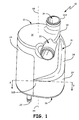
- FIGS. 1 and 2 show a vertically configured particle separator 10.
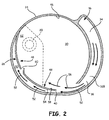
- FIG. 2 is a sectional view of particle separator 10 taken across line 2-2 of FIG. 1.
- FIGS. 1 and 2 also include vessel 12, fluid inlet 14, fluid swirl passage 16, vessel top side 18, first fluid outlet 20, second fluid outlet 22, vessel sidewall 24, vessel bottom side 26, scupper 28, vessel swirl cavity 30, swirl passage ends 32A, 32B, swirl passage curved portions 33, 34, swirl cavity opening 36, scupper entrance 40, axial center line 44, vessel sidewall inner surface 46, scupper wall 48, scupper cavity 50, first fluid flowpath 52, scupper wall first surface 54, second fluid flowpath 56, scupper wall second surface 58, scupper vents 60, and outlet chamber 62.
- fluid inlet 14 is disposed on top side 18 of vessel 12, with first fluid outlet 20 and second fluid outlet 22.
- At least one vessel sidewall 24 extends vertically between top side 18 and bottom side 26.
- vessel 12 is substantially cylindrical and thus can include a single substantially continuous vessel sidewall 24.
- Scupper 28 is disposed within vessel 12 and can be configured to cooperate with other elements of vessel 12 in order to separate incoming fluids into separate flows directed toward first and second fluid outlets 20, 22.
- First fluid outlet 20 can be a drain disposed on bottom side 26 of vessel 12, and is in communication with scupper 28.
- Second fluid outlet 22 is disposed above first fluid outlet 20 and is in communication with vessel swirl cavity 30, defined at least in part by one or more vessel sidewalls 24.
- second fluid outlet 22 can be formed in vessel sidewall 24 proximate to vessel top side 18 and/or fluid inlet 14.
- Swirl cavity 30 of vessel 12 is encompassed by the one or more vessel sidewalls 24.
- portions of fluid swirl passage 16 can be disposed inward of vessel top side 18 and/or first vessel sidewall 24.
- First end 32A of fluid swirl passage 16 is in communication with fluid inlet 14, and second passage end 32B is in communication with vessel swirl cavity 30.
- one or more swirl cavity openings 36 can be disposed at the far end (e.g., second passage end 32B) of fluid swirl passage 16 proximate second curved portion 34.
- Opening 36 which provides communication between fluid inlet 14 and scupper 28, can be spaced circumferentially from, and just upstream of, scupper entrance 40.
- swirl cavity opening 36 is located proximate to an intersection of vessel sidewall 24 and vessel bottom side 26.
- Fluid swirl passage 16 is shaped to impart outward momentum to the incoming fluid mixture, for example, by causing it to follow the curvature of vessel sidewall 24.
- fluid swirl passage 16 can include a first curved portion 33 along vessel top side 22, and second curved portion 34 along vessel sidewall 24. Additional outward momentum can be imparted by placing fluid inlet 14 radially inward of vessel sidewall 24, closer to axial center line 44 of vessel 12. The additional outward momentum from fluid swirl passage 16 allows denser fluid particles suspended in the entering fluid mixture to be thrown outward as they flow toward scupper entrance 40 disposed along inner surface 46 of vessel sidewall 24.
- Scupper 28 can include scupper wall 48 spaced inwardly from vessel sidewall inner surface 46.
- Scupper wall 48 can extend substantially along the axial length of vessel 12 and around a circumferential portion of vessel 12.
- Scupper wall 48 can have a curvature that is similar to a curvature of vessel sidewall 24.
- Scupper wall 48 being spaced apart from vessel sidewall inner surface 46 forms annular scupper cavity 50 around a first circumferential portion of vessel 12.
- scupper wall 48 extends circumferentially around a corresponding portion of vessel sidewall 28, but stops short of the circumferential location of second fluid outlet 22.
- Scupper cavity 50 can also be spaced circumferentially apart from second passage end 32B and opening 36.
- First fluid flowpath 52 extends from fluid inlet 14 to first outlet or drain 20.
- First fluid flowpath 52 also includes fluid swirl passage 16 and scupper cavity 50.
- a first portion of the received fluid is thus directed to flow toward first fluid outlet 20 through fluid swirl passage 16 and into scupper cavity 50 via entrance 40 disposed along vessel sidewall inner surface 46.
- the first portion of received fluid then flows through annular scupper cavity 50 between vessel sidewall 28 and first surface 54 of scupper wall 46, before draining downward into first outlet or drain 20.
- Second fluid flowpath 56 extends to second fluid outlet 22, and also includes fluid swirl passage 16 and vessel swirl cavity 30.
- a second portion of the received fluid is displaced by heavier fluid and particles along vessel sidewall 28, and is thus directed inward of scupper entrance 40 to flow along second opposing surface 58 of scupper wall 48. This fluid is mixed with other fluid in vessel swirl cavity 30 before being ejected from second fluid outlet 22.
- Scupper wall 48 can also include at least one vent 60 to allow fluid communication between scupper cavity 50 and vessel swirl cavity 30. Due to centrifugal forces, the outward momentum imparted to the incoming fluid mixture is maintained so that the denser fluid (e.g., water) follows first flowpath 52 through scupper cavity 50 to outlet chamber 62. In FIG. 2 , outlet chamber 62 surrounds drain 20, both of which are shown in phantom. As will be seen in the exploded view of FIG. 3 , a baffle or similar structure can extend between scupper wall 48 and vessel bottom side 26 to separate outlet chamber 62 from vessel swirl cavity 30 while still allowing communication between scupper cavity 50 and drain 20.
- a baffle or similar structure can extend between scupper wall 48 and vessel bottom side 26 to separate outlet chamber 62 from vessel swirl cavity 30 while still allowing communication between scupper cavity 50 and drain 20.
- different portions of the less dense fluid may generally follow both first flowpath 52 and second flowpath 56.
- the less dense fluid remaining in first flowpath 52 has less outward momentum and can pass easily through scupper vent(s) 60 to rejoin second flowpath 56 through vessel swirl cavity 30, before being ejected from second fluid outlet 22.
- Pressure losses can be minimized as the presence of scupper vents 60 permit the less dense fluid but not the denser fluid to flow freely through scupper wall 48 from first flowpath 52 and into second flowpath 56.
- FIG. 3 shows an exploded view of one example modular embodiment of vessel 12.
- vessel 12 is formed from three separate components: main vessel module 64, scupper wall module 66, and sidewall module 68.
- Main vessel module 64 which may be cast, forms a majority of vessel 12. Similar to FIGS. 1 and 2 , main vessel module 64 includes fluid inlet 14, vessel swirl passage 16, and second fluid outlet 22 proximate vessel top side 18.
- sidewall module 68 which includes a drain serving as first fluid outlet 20, as well as a portion of vessel bottom side 26, is removable from main vessel module 64.
- This and similar configurations allow access to scupper wall module 66, which can be simply installed within vessel 12 to separate scupper cavity 50 (shown in FIGS. 1 and 2 ) from swirl cavity 30 (best shown in FIG. 4 ).
- fluid swirl passage 16 can be separated from second fluid outlet 22 by upper baffle 70.
- Lower baffle 72 separates fluid swirl passage 16 from scupper cavity 50 and/or outlet chamber 62 (shown in FIGS. 1 and 2 ).
- the contiguous scupper wall 48 and lower baffle 72 of scupper wall module 66 can also define a contiguous cavity which includes both scupper cavity 50 (around a circumferential portion of vessel 12), and outlet chamber 62 (around first outlet 20).
- FIG. 4 shows a view into main vessel module 64.
- Fluid swirl passage 16 is open to vessel swirl cavity 30 through opening 36. This can be located proximate an intersection of vessel sidewall 28 and vessel bottom side 30.
- Vessel sidewall 24 defines a portion of fluid swirl passage 16, with the portion between inlet 14 and opening 36 shown in phantom.
- a portion of fluid swirl passage 16 is bounded by vessel sidewall 24 as well as a separate interior passage wall 74.
- one or more openings 36 can be formed through interior passage wall 74 to provide communication between fluid swirl passage 16 and vessel swirl cavity 30.
- a particle separator comprises a vessel, a fluid inlet, a fluid swirl passage, a scupper cavity, a first fluid outlet, and a second fluid outlet.
- the vessel includes a vessel sidewall extending between a vessel top side and a vessel bottom side.
- the fluid swirl passage includes a first passage end in communication with a fluid inlet disposed on the vessel top side.
- a second passage end is in communication with a vessel swirl cavity defined at least in part by an inner surface of the vessel sidewall.
- the scupper cavity includes a scupper entrance disposed along the inner surface of the vessel sidewall, and is spaced circumferentially apart from the second passage end.
- the first fluid outlet is in communication with the scupper cavity and disposed on the vessel bottom side.
- the second fluid outlet is disposed above the first fluid outlet in communication with the vessel swirl cavity.
- the particle separator of the preceding paragraph can optionally include, additionally and/or alternatively, any one or more or all of the following features, configurations and/or additional components:
- a further embodiment of the foregoing particle separator wherein the fluid swirl passage includes a first curved portion along the vessel top side, and a second curved portion along the vessel sidewall.
- a further embodiment of any of the foregoing particle separators wherein the second curved portion of the fluid swirl passage is bounded by a first circumferential portion of the vessel sidewall.
- the scupper cavity comprises a scupper wall spaced radially inward from a second circumferential portion of the vessel sidewall, the scupper wall spaced circumferentially apart from the fluid swirl passage.
- a further embodiment of any of the foregoing particle separators wherein the vessel sidewall and the spaced apart scupper wall define an annular scupper cavity.
- a further embodiment of any of the foregoing particle separators further comprising a lower baffle extending between the scupper wall and the bottom side of the vessel.
- a further embodiment of any of the foregoing particle separators further comprising an upper baffle separating the annular scupper cavity from the second fluid outlet and the vessel swirl cavity.
- a further embodiment of any of the foregoing particle separators further comprising a first fluid flowpath along which a first portion of fluid received in the fluid inlet is directed to flow through the scupper cavity along a first surface of the scupper wall toward the first fluid outlet.
- a further embodiment of any of the foregoing particle separators further comprising a second fluid flowpath along which a second portion of the received fluid is directed to flow into the vessel swirl cavity along a second surface of the scupper wall.
- scupper wall includes at least one vent allowing communication between the first and second fluid flowpaths.
- a particle separator comprises a vessel including a fluid inlet and at least one vertically extending vessel sidewall encompassing a fluid swirl cavity.
- a fluid swirl passage includes a first passage end in communication with the fluid inlet, and a second passage end in communication with the vessel swirl cavity.
- a vertically extending scupper wall is spaced radially inward of the vessel sidewall to define an annular scupper cavity along an outer edge of the vessel swirl cavity.
- a scupper entrance spaced circumferentially apart from the second passage end.
- a fluid outlet is in communication with the vessel swirl cavity, and a drain is in communication with the scupper cavity.
- the particle separator of the preceding paragraph can optionally include, additionally and/or alternatively, any one or more or all of the following features, configurations and/or additional components:
- a further embodiment of any of the foregoing particle separators wherein the fluid swirl passage including a first curved portion proximate the fluid inlet, and a second curved portion along the at least one vessel sidewall.
- a further embodiment of any of the foregoing particle separators further comprising a lower baffle extending between the scupper wall and the bottom side of the vessel, the lower baffle defining an outlet chamber spaced apart from the fluid swirl passage and the vessel swirl cavity; and an upper baffle separating the scupper cavity from the vessel swirl cavity.
- scupper wall includes at least one vent allowing communication between the scupper cavity from the vessel swirl cavity.
Landscapes
- Physics & Mathematics (AREA)
- Chemical & Material Sciences (AREA)
- Chemical Kinetics & Catalysis (AREA)
- Fluid Mechanics (AREA)
- Health & Medical Sciences (AREA)
- General Health & Medical Sciences (AREA)
- Pulmonology (AREA)
- Engineering & Computer Science (AREA)
- Aviation & Aerospace Engineering (AREA)
- Geometry (AREA)
- Cyclones (AREA)
- Separating Particles In Gases By Inertia (AREA)
Abstract
Description
- The subject matter disclosed herein relates to a particle separator and, more particularly, to a particle separator for airflow into a cabin of an aircraft.
- In aircraft, airflow from a condenser heat exchanger typically has liquid water particles, or droplets, mixed together with air. It is often desirable for these water droplets or other particles to be collected before the airflow is permitted to proceed toward the occupied cabin. The water droplets can be removed to thereby prevent problems with moisture and humidity in the occupied cabin. Various methods and systems have been proposed to collect and then remove the water droplets. These include forcing the airflow to swirl such that the water droplets travel to an outer wall of the swirler due to centrifugal force. At the outer wall, the water droplets are collected for removal. In current applications, however, air velocities in the inlet ducts of the swirlers are very high. These high velocities lead to large pressure losses.
- In one aspect, a particle separator comprises a vessel, a fluid inlet, a fluid swirl passage, a scupper cavity, a first fluid outlet, and a second fluid outlet. The vessel includes a vessel sidewall extending between a vessel top side and a vessel bottom side. The fluid swirl passage includes a first passage end in communication with a fluid inlet disposed on the vessel top side. A second passage end is in communication with a vessel swirl cavity defined at least in part by an inner surface of the vessel sidewall. The scupper cavity includes a scupper entrance disposed along the inner surface of the vessel sidewall, and is spaced circumferentially apart from the second passage end. The first fluid outlet is in communication with the scupper cavity and disposed on the vessel bottom side. The second fluid outlet is disposed above the first fluid outlet in communication with the vessel swirl cavity.
- In another aspect, a particle separator comprises a vessel including a fluid inlet and at least one vertically extending vessel sidewall encompassing a fluid swirl cavity. A fluid swirl passage includes a first passage end in communication with the fluid inlet, and a second passage end in communication with the vessel swirl cavity. A vertically extending scupper wall is spaced radially inward of the vessel sidewall to define an annular scupper cavity along an outer edge of the vessel swirl cavity. A scupper entrance spaced circumferentially apart from the second passage end. A fluid outlet is in communication with the vessel swirl cavity, and a drain is in communication with the scupper cavity.
-
-
FIG. 1 is a plan view of a particle separator. -
FIG. 2 is sectional view of the particle separator taken across line 2-2 ofFIG. 1 . -
FIG. 3 shows an example modular construction of a particle separator. -
FIG. 4 is a view into a vessel module shown inFIG. 3 . - In certain embodiments, high-speed inlet air is ducted to a vertically extending sidewall of a substantially cylindrical vessel. A scupper arrangement on the sides of the vessel can provide for separation of a first fluid or particles such as water droplets entrained in inlet air. The entrained fluid can be collected along the outer wall due to centrifugal force. The outlet is arranged to recover the energy from the swirling air without allowing re-entrainment of the water droplets. This recovery results in low pressure losses. Further, because no swirl vanes are needed, a volume of the device is minimized.
-
FIGS. 1 and2 show a vertically configuredparticle separator 10.FIG. 2 is a sectional view ofparticle separator 10 taken across line 2-2 ofFIG. 1. FIGS. 1 and2 also includevessel 12,fluid inlet 14,fluid swirl passage 16, vesseltop side 18,first fluid outlet 20,second fluid outlet 22,vessel sidewall 24,vessel bottom side 26,scupper 28,vessel swirl cavity 30,swirl passage ends portions swirl cavity opening 36,scupper entrance 40,axial center line 44, vessel sidewallinner surface 46,scupper wall 48, scupper cavity 50,first fluid flowpath 52, scupper wallfirst surface 54,second fluid flowpath 56, scupper wallsecond surface 58,scupper vents 60, andoutlet chamber 62. - With respect to
FIGS. 1 and2 ,fluid inlet 14 is disposed ontop side 18 ofvessel 12, withfirst fluid outlet 20 andsecond fluid outlet 22. At least onevessel sidewall 24 extends vertically betweentop side 18 andbottom side 26. In certain embodiments,vessel 12 is substantially cylindrical and thus can include a single substantiallycontinuous vessel sidewall 24.Scupper 28 is disposed withinvessel 12 and can be configured to cooperate with other elements ofvessel 12 in order to separate incoming fluids into separate flows directed toward first andsecond fluid outlets -
First fluid outlet 20 can be a drain disposed onbottom side 26 ofvessel 12, and is in communication withscupper 28.Second fluid outlet 22 is disposed abovefirst fluid outlet 20 and is in communication withvessel swirl cavity 30, defined at least in part by one ormore vessel sidewalls 24. In certain embodiments,second fluid outlet 22 can be formed invessel sidewall 24 proximate to vesseltop side 18 and/orfluid inlet 14.Swirl cavity 30 ofvessel 12 is encompassed by the one ormore vessel sidewalls 24. - As shown in
FIGS. 1 and2 , portions offluid swirl passage 16 can be disposed inward of vesseltop side 18 and/orfirst vessel sidewall 24.First end 32A offluid swirl passage 16 is in communication withfluid inlet 14, andsecond passage end 32B is in communication withvessel swirl cavity 30. As best seen inFIG. 2 , one or moreswirl cavity openings 36 can be disposed at the far end (e.g.,second passage end 32B) offluid swirl passage 16 proximate secondcurved portion 34.Opening 36, which provides communication betweenfluid inlet 14 andscupper 28, can be spaced circumferentially from, and just upstream of, scupperentrance 40. In certain embodiments,swirl cavity opening 36 is located proximate to an intersection ofvessel sidewall 24 andvessel bottom side 26. -
Fluid swirl passage 16 is shaped to impart outward momentum to the incoming fluid mixture, for example, by causing it to follow the curvature ofvessel sidewall 24. For example,fluid swirl passage 16 can include a firstcurved portion 33 along vesseltop side 22, and secondcurved portion 34 alongvessel sidewall 24. Additional outward momentum can be imparted by placingfluid inlet 14 radially inward ofvessel sidewall 24, closer toaxial center line 44 ofvessel 12. The additional outward momentum fromfluid swirl passage 16 allows denser fluid particles suspended in the entering fluid mixture to be thrown outward as they flow towardscupper entrance 40 disposed alonginner surface 46 ofvessel sidewall 24. -
Scupper 28 can includescupper wall 48 spaced inwardly from vessel sidewallinner surface 46.Scupper wall 48 can extend substantially along the axial length ofvessel 12 and around a circumferential portion ofvessel 12.Scupper wall 48 can have a curvature that is similar to a curvature ofvessel sidewall 24. -
Scupper wall 48, being spaced apart from vessel sidewallinner surface 46 forms annular scupper cavity 50 around a first circumferential portion ofvessel 12. In certain embodiments,scupper wall 48 extends circumferentially around a corresponding portion ofvessel sidewall 28, but stops short of the circumferential location ofsecond fluid outlet 22. Scupper cavity 50 can also be spaced circumferentially apart fromsecond passage end 32B and opening 36. Thus, the incoming fluid mixture entering by way ofinlet 14 can be provided with outward momentum before reachingscupper entrance 40. Between opening 36 and scupperentrance 40, different portions of the incoming fluid proceeds along one of two fluid flow paths through the rest ofvessel 12. -
First fluid flowpath 52 extends fromfluid inlet 14 to first outlet ordrain 20.First fluid flowpath 52 also includesfluid swirl passage 16 and scupper cavity 50. A first portion of the received fluid is thus directed to flow toward firstfluid outlet 20 throughfluid swirl passage 16 and into scupper cavity 50 viaentrance 40 disposed along vessel sidewallinner surface 46. The first portion of received fluid then flows through annular scupper cavity 50 betweenvessel sidewall 28 andfirst surface 54 ofscupper wall 46, before draining downward into first outlet or drain 20. -
Second fluid flowpath 56 extends to secondfluid outlet 22, and also includesfluid swirl passage 16 andvessel swirl cavity 30. A second portion of the received fluid is displaced by heavier fluid and particles alongvessel sidewall 28, and is thus directed inward ofscupper entrance 40 to flow along second opposingsurface 58 ofscupper wall 48. This fluid is mixed with other fluid invessel swirl cavity 30 before being ejected from secondfluid outlet 22. -
Scupper wall 48 can also include at least onevent 60 to allow fluid communication between scupper cavity 50 andvessel swirl cavity 30. Due to centrifugal forces, the outward momentum imparted to the incoming fluid mixture is maintained so that the denser fluid (e.g., water) followsfirst flowpath 52 through scupper cavity 50 tooutlet chamber 62. InFIG. 2 ,outlet chamber 62 surroundsdrain 20, both of which are shown in phantom. As will be seen in the exploded view ofFIG. 3 , a baffle or similar structure can extend betweenscupper wall 48 and vesselbottom side 26 to separateoutlet chamber 62 fromvessel swirl cavity 30 while still allowing communication between scupper cavity 50 anddrain 20. - Returning to
FIG. 2 , different portions of the less dense fluid (e.g., air) may generally follow bothfirst flowpath 52 andsecond flowpath 56. The less dense fluid remaining infirst flowpath 52 has less outward momentum and can pass easily through scupper vent(s) 60 to rejoinsecond flowpath 56 throughvessel swirl cavity 30, before being ejected from secondfluid outlet 22. Pressure losses can be minimized as the presence of scupper vents 60 permit the less dense fluid but not the denser fluid to flow freely throughscupper wall 48 fromfirst flowpath 52 and intosecond flowpath 56. -
FIG. 3 shows an exploded view of one example modular embodiment ofvessel 12. In this example,vessel 12 is formed from three separate components:main vessel module 64,scupper wall module 66, andsidewall module 68.Main vessel module 64, which may be cast, forms a majority ofvessel 12. Similar toFIGS. 1 and2 ,main vessel module 64 includesfluid inlet 14,vessel swirl passage 16, and secondfluid outlet 22 proximate vesseltop side 18. However,sidewall module 68, which includes a drain serving as firstfluid outlet 20, as well as a portion of vesselbottom side 26, is removable frommain vessel module 64. This and similar configurations allow access to scupperwall module 66, which can be simply installed withinvessel 12 to separate scupper cavity 50 (shown inFIGS. 1 and2 ) from swirl cavity 30 (best shown inFIG. 4 ). - To limit mixing of flows to designated areas, and maintain a compact shape of
vessel 12,fluid swirl passage 16 can be separated from secondfluid outlet 22 byupper baffle 70.Lower baffle 72 separatesfluid swirl passage 16 from scupper cavity 50 and/or outlet chamber 62 (shown inFIGS. 1 and2 ). Thecontiguous scupper wall 48 andlower baffle 72 ofscupper wall module 66 can also define a contiguous cavity which includes both scupper cavity 50 (around a circumferential portion of vessel 12), and outlet chamber 62 (around first outlet 20). -
FIG. 4 shows a view intomain vessel module 64.Fluid swirl passage 16 is open tovessel swirl cavity 30 throughopening 36. This can be located proximate an intersection ofvessel sidewall 28 and vesselbottom side 30.Vessel sidewall 24 defines a portion offluid swirl passage 16, with the portion betweeninlet 14 andopening 36 shown in phantom. In certain embodiments, a portion offluid swirl passage 16 is bounded byvessel sidewall 24 as well as a separateinterior passage wall 74. In these embodiments, one ormore openings 36 can be formed throughinterior passage wall 74 to provide communication betweenfluid swirl passage 16 andvessel swirl cavity 30. - The following are non-exclusive descriptions of possible embodiments of the present invention.
- A particle separator comprises a vessel, a fluid inlet, a fluid swirl passage, a scupper cavity, a first fluid outlet, and a second fluid outlet. The vessel includes a vessel sidewall extending between a vessel top side and a vessel bottom side. The fluid swirl passage includes a first passage end in communication with a fluid inlet disposed on the vessel top side. A second passage end is in communication with a vessel swirl cavity defined at least in part by an inner surface of the vessel sidewall. The scupper cavity includes a scupper entrance disposed along the inner surface of the vessel sidewall, and is spaced circumferentially apart from the second passage end. The first fluid outlet is in communication with the scupper cavity and disposed on the vessel bottom side. The second fluid outlet is disposed above the first fluid outlet in communication with the vessel swirl cavity.
- The particle separator of the preceding paragraph can optionally include, additionally and/or alternatively, any one or more or all of the following features, configurations and/or additional components:
- A further embodiment of the foregoing particle separator, wherein the fluid swirl passage includes a first curved portion along the vessel top side, and a second curved portion along the vessel sidewall.
- A further embodiment of any of the foregoing particle separators, wherein the fluid inlet is disposed radially inward of vessel sidewall.
- A further embodiment of any of the foregoing particle separators, wherein the second curved portion of the fluid swirl passage is bounded by a first circumferential portion of the vessel sidewall.
- A further embodiment of any of the foregoing particle separators, wherein the first fluid outlet comprises a drain formed on the bottom side of the vessel.
- A further embodiment of any of the foregoing particle separators, wherein the second fluid outlet is formed in the vessel sidewall proximate to the top side of the vessel.
- A further embodiment of any of the foregoing particle separators, wherein the scupper cavity comprises a scupper wall spaced radially inward from a second circumferential portion of the vessel sidewall, the scupper wall spaced circumferentially apart from the fluid swirl passage.
- A further embodiment of any of the foregoing particle separators, wherein the vessel sidewall and the spaced apart scupper wall define an annular scupper cavity.
- A further embodiment of any of the foregoing particle separators, further comprising a lower baffle extending between the scupper wall and the bottom side of the vessel.
- A further embodiment of any of the foregoing particle separators, wherein the bottom side of vessel and the lower baffle define an outlet chamber in communication with the annular scupper cavity.
- A further embodiment of any of the foregoing particle separators, further comprising an upper baffle separating the annular scupper cavity from the second fluid outlet and the vessel swirl cavity.
- A further embodiment of any of the foregoing particle separators, further comprising a first fluid flowpath along which a first portion of fluid received in the fluid inlet is directed to flow through the scupper cavity along a first surface of the scupper wall toward the first fluid outlet.
- A further embodiment of any of the foregoing particle separators, further comprising a second fluid flowpath along which a second portion of the received fluid is directed to flow into the vessel swirl cavity along a second surface of the scupper wall.
- A further embodiment of any of the foregoing particle separators, wherein the scupper wall includes at least one vent allowing communication between the first and second fluid flowpaths.
- A particle separator comprises a vessel including a fluid inlet and at least one vertically extending vessel sidewall encompassing a fluid swirl cavity. A fluid swirl passage includes a first passage end in communication with the fluid inlet, and a second passage end in communication with the vessel swirl cavity. A vertically extending scupper wall is spaced radially inward of the vessel sidewall to define an annular scupper cavity along an outer edge of the vessel swirl cavity. A scupper entrance spaced circumferentially apart from the second passage end. A fluid outlet is in communication with the vessel swirl cavity, and a drain is in communication with the scupper cavity.
- The particle separator of the preceding paragraph can optionally include, additionally and/or alternatively, any one or more or all of the following features, configurations and/or additional components:
- A further embodiment of the foregoing particle separator, wherein the fluid outlet is formed in an upper portion of the at least one vessel sidewall.
- A further embodiment of any of the foregoing particle separators, wherein the fluid swirl passage including a first curved portion proximate the fluid inlet, and a second curved portion along the at least one vessel sidewall.
- A further embodiment of any of the foregoing particle separators, wherein the fluid inlet is disposed radially inward of the at least one vessel sidewall.
- A further embodiment of any of the foregoing particle separators, further comprising a lower baffle extending between the scupper wall and the bottom side of the vessel, the lower baffle defining an outlet chamber spaced apart from the fluid swirl passage and the vessel swirl cavity; and an upper baffle separating the scupper cavity from the vessel swirl cavity.
- A further embodiment of any of the foregoing particle separators, wherein the scupper wall includes at least one vent allowing communication between the scupper cavity from the vessel swirl cavity.
- While the invention has been described with reference to an exemplary embodiment(s), it will be understood by those skilled in the art that various changes may be made and equivalents may be substituted for elements thereof without departing from the scope of the invention. In addition, many modifications may be made to adapt a particular situation or material to the teachings of the invention without departing from the essential scope thereof. Therefore, it is intended that the invention not be limited to the particular embodiment(s) disclosed, but that the invention will include all embodiments falling within the scope of the appended claims.
Claims (15)
- A particle separator (10) comprising:a vessel (12) including a vessel sidewall (24) extending between a vessel top side (18) and a vessel bottom side (26);a fluid inlet (14) disposed on the vessel top side (18);a fluid swirl passage (16) including a first passage end (32A) in communication with the fluid inlet (14), and a second passage end (328) in communication with a vessel swirl cavity (30) defined at least in part by an inner surface (46) of the vessel sidewall (24);a scupper cavity (50) including a scupper entrance (40) disposed along the inner surface of the vessel sidewall (24) and spaced circumferentially apart from the second passage end (32B);a first fluid outlet (20) in communication with the scupper cavity (50) and disposed on the vessel bottom side (26); anda second fluid outlet (22) disposed above the first fluid outlet (20) in communication with the vessel swirl cavity (30).
- The particle separator (10) of claim 1, wherein the fluid swirl passage (16) includes a first curved portion (33) along the vessel top side (22), and a second curved portion (34) along the vessel sidewall (24), and optionally wherein the second curved portion (34) of the fluid swirl passage (16) is bounded by a first circumferential portion of the vessel sidewall (24).
- The particle separator (10) of claim 1 or 2, wherein the fluid inlet (14) is disposed radially inward of the vessel sidewall (24).
- The particle separator (10) of any preceding claim, wherein the first fluid outlet (20) comprises a drain formed on the bottom side (26) of the vessel (12).
- The particle separator (10) of any preceding claim, wherein the second fluid outlet (22) is formed in the vessel sidewall (24) proximate to the top side (18) of the vessel (12).
- The particle separator (10) of any preceding claim, wherein the scupper cavity (50) comprises a scupper wall (48) spaced radially inward from a second circumferential portion of the vessel sidewall (24), the scupper wall (48) spaced circumferentially apart from the fluid swirl passage (16), and optionally wherein the vessel sidewall (24) and the spaced apart scupper wall (48) define an annular scupper cavity (50).
- The particle separator (10) of claim 6, further comprising a lower baffle (72) extending between the scupper wall (48) and the bottom side (26) of the vessel (12), and optionally wherein the bottom side (26) of the vessel (12) and the lower baffle (72) define an outlet chamber (62) in communication with the annular scupper cavity (50).
- The particle separator (10) of claim 6 or 7, further comprising an upper baffle (70) separating the annular scupper cavity (50) from the second fluid outlet (22) and the vessel swirl cavity (30).
- The particle separator (10) of any of claims 6 to 8, further comprising a first fluid flowpath (52) along which a first portion of fluid received in the fluid inlet (14) is directed to flow through the scupper cavity (50) along a first surface (54) of the scupper wall (48) toward the first fluid outlet (20).
- The particle separator (10) of claim 9, further comprising a second fluid flowpath (56) along which a second portion of the received fluid is directed to flow into the vessel swirl cavity (30) along a second surface (58) of the scupper wall (48), and optionally wherein the scupper wall (48) includes at least one vent (60) allowing communication between the first and second fluid flowpaths (52).
- A particle separator (10), comprising:a vessel (12) including a fluid inlet (14) and at least one vertically extending vessel sidewall (24) encompassing a fluid swirl cavity (30);a fluid swirl passage (18) including a first passage end (32A) in communication with the fluid inlet (14), and a second passage end (32B) in communication with the vessel swirl cavity (30);a vertically extending scupper wall (48) spaced radially inward of the vessel sidewall (24) to define an annular scupper cavity (50) along an outer edge of the fluid swirl cavity (30);a scupper entrance (40) spaced circumferentially apart from the second passage end (32B);a fluid outlet (22) in communication with the vessel swirl cavity (30); anda drain (20) in communication with the scupper cavity (50).
- The particle separator (10) of claim 11, wherein the fluid outlet (22) is formed in an upper portion of the at least one vessel sidewall (24).
- The particle separator (10) of claim 11 or 12, wherein the fluid swirl passage (16) includes a first curved portion (33) proximate the fluid inlet (14), and a second curved portion (34) along the at least one vessel sidewall (24), and optionally wherein the fluid inlet (14) is disposed radially inward of the at least one vessel sidewall (24).
- The particle separator (10) of any of claims 11 to 13, further comprising:a lower baffle (72) extending between the scupper wall (48) and the bottom side (26) of the vessel (12), the lower baffle (72) defining an outlet chamber (62) spaced apart from the fluid swirl passage (16) and the vessel swirl cavity (30); andan upper baffle (70) separating the scupper cavity (50) from the vessel swirl cavity (30).
- The particle separator (10) of any of claims 11 to 14, wherein the scupper wall (48) includes at least one vent (60) allowing communication between the scupper cavity (50) from the vessel swirl cavity (30).
Applications Claiming Priority (1)
| Application Number | Priority Date | Filing Date | Title |
|---|---|---|---|
| US13/872,609 US9272293B2 (en) | 2013-04-29 | 2013-04-29 | Particle separator |
Publications (2)
| Publication Number | Publication Date |
|---|---|
| EP2799341A1 true EP2799341A1 (en) | 2014-11-05 |
| EP2799341B1 EP2799341B1 (en) | 2018-06-06 |
Family
ID=50980899
Family Applications (1)
| Application Number | Title | Priority Date | Filing Date |
|---|---|---|---|
| EP14166344.3A Active EP2799341B1 (en) | 2013-04-29 | 2014-04-29 | Particle separator |
Country Status (2)
| Country | Link |
|---|---|
| US (1) | US9272293B2 (en) |
| EP (1) | EP2799341B1 (en) |
Cited By (1)
| Publication number | Priority date | Publication date | Assignee | Title |
|---|---|---|---|---|
| EP3320961A1 (en) * | 2016-11-14 | 2018-05-16 | Hamilton Sundstrand Corporation | Compact water extractor |
Families Citing this family (8)
| Publication number | Priority date | Publication date | Assignee | Title |
|---|---|---|---|---|
| KR101610464B1 (en) * | 2014-04-11 | 2016-04-07 | 현대자동차주식회사 | Seperator for fluid separation and SCR urea solution infusion system using the same |
| US20160325214A1 (en) * | 2015-05-06 | 2016-11-10 | Caterpillar Inc. | Contaminate separator for seals of rotating shafts |
| US10023317B2 (en) * | 2015-06-23 | 2018-07-17 | The Boeing Company | Flight deck takeoff duct and trim air mix muff |
| US10513979B2 (en) * | 2017-01-24 | 2019-12-24 | General Electric Company | Asymmetric inlet particle separator system |
| US10697328B2 (en) * | 2017-09-13 | 2020-06-30 | General Electric Company | Device and method for removing particles from air flow |
| CN107930256B (en) * | 2017-11-24 | 2023-08-01 | 晋能控股煤业集团有限公司 | Collision type wind-water separator |
| DE102018130809A1 (en) * | 2018-12-04 | 2020-06-04 | Dürr Systems Ag | Collection device for rinsing media of an atomizer |
| US12065251B2 (en) | 2021-06-29 | 2024-08-20 | Hamilton Sundstrand Corporation | Centrifugal water collector with conical water scupper |
Citations (3)
| Publication number | Priority date | Publication date | Assignee | Title |
|---|---|---|---|---|
| GB2230977A (en) * | 1989-04-24 | 1990-11-07 | Ingersoll Rand Co | Centrifugal separator |
| WO2002009846A2 (en) * | 2000-07-28 | 2002-02-07 | Honeywell International Inc. | Two-stage water extractor |
| EP1621243A1 (en) * | 2004-07-28 | 2006-02-01 | Liebherr-Aerospace Lindenberg GmbH | Water separator for air conditioning systems |
Family Cites Families (18)
| Publication number | Priority date | Publication date | Assignee | Title |
|---|---|---|---|---|
| US3993463A (en) * | 1975-08-28 | 1976-11-23 | The United States Of America As Represented By The Secretary Of The Army | Particle separator for turbine engines of aircraft |
| US4035171A (en) * | 1976-04-26 | 1977-07-12 | John Zink Company | Gas liquid separator for flare systems |
| US4304094A (en) | 1979-11-16 | 1981-12-08 | United Technologies Corp. | Engine air particle separator for use with gas turbine engine |
| US4292050A (en) | 1979-11-15 | 1981-09-29 | Linhardt & Associates, Inc. | Curved duct separator for removing particulate matter from a carrier gas |
| US4527387A (en) | 1982-11-26 | 1985-07-09 | General Electric Company | Particle separator scroll vanes |
| US4685942A (en) | 1982-12-27 | 1987-08-11 | General Electric Company | Axial flow inlet particle separator |
| US6688558B2 (en) | 1999-11-23 | 2004-02-10 | The Boeing Company | Method and apparatus for aircraft inlet ice protection |
| US6562108B2 (en) | 2000-07-24 | 2003-05-13 | Aep Emtech, Llc | Stack liquid separator and method of use |
| NO318709B1 (en) | 2000-12-22 | 2005-05-02 | Statoil Asa | Device for separating a liquid from a multiphase fluid stream |
| US6852146B2 (en) | 2002-07-12 | 2005-02-08 | Acs Industries, Lp | Pocket vane particle and droplet eliminator |
| US20050194295A1 (en) | 2002-10-02 | 2005-09-08 | North John H. | Air/particle separator |
| JP4861407B2 (en) | 2005-04-13 | 2012-01-25 | シコルスキー エアクラフト コーポレイション | Integrated engine air particle filter assembly |
| US20080047425A1 (en) | 2006-08-23 | 2008-02-28 | United Technologies Corporation | Mission adaptable inlet particle separator |
| US7691185B2 (en) | 2006-12-14 | 2010-04-06 | Honeywell International Inc. | Recirculating Coanda water extractor |
| US8092145B2 (en) | 2008-10-28 | 2012-01-10 | Pratt & Whitney Canada Corp. | Particle separator and separating method for gas turbine engine |
| US8561411B2 (en) | 2009-09-02 | 2013-10-22 | United Technologies Corporation | Air particle separator for a gas turbine engine |
| US9446342B2 (en) | 2010-06-25 | 2016-09-20 | Abbas Motakef | Cyclone induced sweeping flow separator |
| US8425641B2 (en) | 2010-06-30 | 2013-04-23 | General Electric Company | Inlet air filtration system |
-
2013
- 2013-04-29 US US13/872,609 patent/US9272293B2/en active Active
-
2014
- 2014-04-29 EP EP14166344.3A patent/EP2799341B1/en active Active
Patent Citations (3)
| Publication number | Priority date | Publication date | Assignee | Title |
|---|---|---|---|---|
| GB2230977A (en) * | 1989-04-24 | 1990-11-07 | Ingersoll Rand Co | Centrifugal separator |
| WO2002009846A2 (en) * | 2000-07-28 | 2002-02-07 | Honeywell International Inc. | Two-stage water extractor |
| EP1621243A1 (en) * | 2004-07-28 | 2006-02-01 | Liebherr-Aerospace Lindenberg GmbH | Water separator for air conditioning systems |
Cited By (3)
| Publication number | Priority date | Publication date | Assignee | Title |
|---|---|---|---|---|
| EP3320961A1 (en) * | 2016-11-14 | 2018-05-16 | Hamilton Sundstrand Corporation | Compact water extractor |
| US10265651B2 (en) | 2016-11-14 | 2019-04-23 | Hamilton Sundstrand Corporation | Compact water extractor |
| US10639574B2 (en) | 2016-11-14 | 2020-05-05 | Hamilton Sundstrand Corporation | Method of extracting water |
Also Published As
| Publication number | Publication date |
|---|---|
| EP2799341B1 (en) | 2018-06-06 |
| US9272293B2 (en) | 2016-03-01 |
| US20140318088A1 (en) | 2014-10-30 |
Similar Documents
| Publication | Publication Date | Title |
|---|---|---|
| US9272293B2 (en) | Particle separator | |
| US9737835B2 (en) | Methods and apparatuses for separating liquid particles from a gas-liquid stream | |
| US9795898B2 (en) | Cyclonic separator system | |
| CN102575677B (en) | Multi-stage oil separation system including cyclone separation stages | |
| US9789429B2 (en) | Pre-separating vane diffuser and method for introducing a flow-mixture in a separator | |
| US2222930A (en) | Centrifugal separator | |
| JP6336478B2 (en) | Cyclone, cyclone mist removing device and method of use | |
| JP2001246216A (en) | Gas-liquid separation device | |
| EP2871338B1 (en) | Oil separator | |
| EP2712531A2 (en) | Cyclonic separator | |
| CN103431810A (en) | Cyclone separation type dust cup | |
| EP2868878B1 (en) | Oil separator | |
| US20100011961A1 (en) | Fluid separating vessel | |
| JP5759341B2 (en) | Cyclone equipment | |
| EP3620222A1 (en) | High pressure water collector with radial diffuser | |
| WO2011010849A2 (en) | Cyclone separator | |
| EP2799124B1 (en) | Particle separator | |
| EP3083007B1 (en) | Method and wet scrubber for removing particles from gases | |
| KR100556440B1 (en) | Multi Cyclone Dust Collector | |
| JP6567003B2 (en) | Powder separator | |
| AU2016361458A1 (en) | A cyclonic vacuum cleaner | |
| CA2886661C (en) | Improved cyclonic separator system | |
| CN219150438U (en) | Cyclone separator | |
| CN215605400U (en) | A separator and cleaning equipment including the same |
Legal Events
| Date | Code | Title | Description |
|---|---|---|---|
| PUAI | Public reference made under article 153(3) epc to a published international application that has entered the european phase |
Free format text: ORIGINAL CODE: 0009012 |
|
| 17P | Request for examination filed |
Effective date: 20140429 |
|
| AK | Designated contracting states |
Kind code of ref document: A1 Designated state(s): AL AT BE BG CH CY CZ DE DK EE ES FI FR GB GR HR HU IE IS IT LI LT LU LV MC MK MT NL NO PL PT RO RS SE SI SK SM TR |
|
| AX | Request for extension of the european patent |
Extension state: BA ME |
|
| R17P | Request for examination filed (corrected) |
Effective date: 20150505 |
|
| RBV | Designated contracting states (corrected) |
Designated state(s): AL AT BE BG CH CY CZ DE DK EE ES FI FR GB GR HR HU IE IS IT LI LT LU LV MC MK MT NL NO PL PT RO RS SE SI SK SM TR |
|
| GRAP | Despatch of communication of intention to grant a patent |
Free format text: ORIGINAL CODE: EPIDOSNIGR1 |
|
| STAA | Information on the status of an ep patent application or granted ep patent |
Free format text: STATUS: GRANT OF PATENT IS INTENDED |
|
| RIC1 | Information provided on ipc code assigned before grant |
Ipc: B04C 5/081 20060101ALI20171127BHEP Ipc: B64D 13/00 20060101AFI20171127BHEP Ipc: F24F 3/16 20060101ALI20171127BHEP Ipc: B04C 5/14 20060101ALI20171127BHEP Ipc: B01D 45/16 20060101ALI20171127BHEP Ipc: B04C 5/103 20060101ALI20171127BHEP Ipc: B64D 13/06 20060101ALI20171127BHEP Ipc: B04C 5/06 20060101ALI20171127BHEP |
|
| INTG | Intention to grant announced |
Effective date: 20171220 |
|
| GRAS | Grant fee paid |
Free format text: ORIGINAL CODE: EPIDOSNIGR3 |
|
| GRAA | (expected) grant |
Free format text: ORIGINAL CODE: 0009210 |
|
| STAA | Information on the status of an ep patent application or granted ep patent |
Free format text: STATUS: THE PATENT HAS BEEN GRANTED |
|
| AK | Designated contracting states |
Kind code of ref document: B1 Designated state(s): AL AT BE BG CH CY CZ DE DK EE ES FI FR GB GR HR HU IE IS IT LI LT LU LV MC MK MT NL NO PL PT RO RS SE SI SK SM TR |
|
| REG | Reference to a national code |
Ref country code: GB Ref legal event code: FG4D |
|
| REG | Reference to a national code |
Ref country code: CH Ref legal event code: EP Ref country code: AT Ref legal event code: REF Ref document number: 1005804 Country of ref document: AT Kind code of ref document: T Effective date: 20180615 |
|
| REG | Reference to a national code |
Ref country code: IE Ref legal event code: FG4D |
|
| REG | Reference to a national code |
Ref country code: DE Ref legal event code: R096 Ref document number: 602014026558 Country of ref document: DE |
|
| REG | Reference to a national code |
Ref country code: NL Ref legal event code: MP Effective date: 20180606 |
|
| REG | Reference to a national code |
Ref country code: LT Ref legal event code: MG4D |
|
| PG25 | Lapsed in a contracting state [announced via postgrant information from national office to epo] |
Ref country code: ES Free format text: LAPSE BECAUSE OF FAILURE TO SUBMIT A TRANSLATION OF THE DESCRIPTION OR TO PAY THE FEE WITHIN THE PRESCRIBED TIME-LIMIT Effective date: 20180606 Ref country code: SE Free format text: LAPSE BECAUSE OF FAILURE TO SUBMIT A TRANSLATION OF THE DESCRIPTION OR TO PAY THE FEE WITHIN THE PRESCRIBED TIME-LIMIT Effective date: 20180606 Ref country code: CY Free format text: LAPSE BECAUSE OF FAILURE TO SUBMIT A TRANSLATION OF THE DESCRIPTION OR TO PAY THE FEE WITHIN THE PRESCRIBED TIME-LIMIT Effective date: 20180606 Ref country code: NO Free format text: LAPSE BECAUSE OF FAILURE TO SUBMIT A TRANSLATION OF THE DESCRIPTION OR TO PAY THE FEE WITHIN THE PRESCRIBED TIME-LIMIT Effective date: 20180906 Ref country code: FI Free format text: LAPSE BECAUSE OF FAILURE TO SUBMIT A TRANSLATION OF THE DESCRIPTION OR TO PAY THE FEE WITHIN THE PRESCRIBED TIME-LIMIT Effective date: 20180606 Ref country code: BG Free format text: LAPSE BECAUSE OF FAILURE TO SUBMIT A TRANSLATION OF THE DESCRIPTION OR TO PAY THE FEE WITHIN THE PRESCRIBED TIME-LIMIT Effective date: 20180906 Ref country code: LT Free format text: LAPSE BECAUSE OF FAILURE TO SUBMIT A TRANSLATION OF THE DESCRIPTION OR TO PAY THE FEE WITHIN THE PRESCRIBED TIME-LIMIT Effective date: 20180606 |
|
| PG25 | Lapsed in a contracting state [announced via postgrant information from national office to epo] |
Ref country code: GR Free format text: LAPSE BECAUSE OF FAILURE TO SUBMIT A TRANSLATION OF THE DESCRIPTION OR TO PAY THE FEE WITHIN THE PRESCRIBED TIME-LIMIT Effective date: 20180907 Ref country code: HR Free format text: LAPSE BECAUSE OF FAILURE TO SUBMIT A TRANSLATION OF THE DESCRIPTION OR TO PAY THE FEE WITHIN THE PRESCRIBED TIME-LIMIT Effective date: 20180606 Ref country code: LV Free format text: LAPSE BECAUSE OF FAILURE TO SUBMIT A TRANSLATION OF THE DESCRIPTION OR TO PAY THE FEE WITHIN THE PRESCRIBED TIME-LIMIT Effective date: 20180606 Ref country code: RS Free format text: LAPSE BECAUSE OF FAILURE TO SUBMIT A TRANSLATION OF THE DESCRIPTION OR TO PAY THE FEE WITHIN THE PRESCRIBED TIME-LIMIT Effective date: 20180606 |
|
| REG | Reference to a national code |
Ref country code: AT Ref legal event code: MK05 Ref document number: 1005804 Country of ref document: AT Kind code of ref document: T Effective date: 20180606 |
|
| PG25 | Lapsed in a contracting state [announced via postgrant information from national office to epo] |
Ref country code: NL Free format text: LAPSE BECAUSE OF FAILURE TO SUBMIT A TRANSLATION OF THE DESCRIPTION OR TO PAY THE FEE WITHIN THE PRESCRIBED TIME-LIMIT Effective date: 20180606 |
|
| PG25 | Lapsed in a contracting state [announced via postgrant information from national office to epo] |
Ref country code: CZ Free format text: LAPSE BECAUSE OF FAILURE TO SUBMIT A TRANSLATION OF THE DESCRIPTION OR TO PAY THE FEE WITHIN THE PRESCRIBED TIME-LIMIT Effective date: 20180606 Ref country code: RO Free format text: LAPSE BECAUSE OF FAILURE TO SUBMIT A TRANSLATION OF THE DESCRIPTION OR TO PAY THE FEE WITHIN THE PRESCRIBED TIME-LIMIT Effective date: 20180606 Ref country code: IS Free format text: LAPSE BECAUSE OF FAILURE TO SUBMIT A TRANSLATION OF THE DESCRIPTION OR TO PAY THE FEE WITHIN THE PRESCRIBED TIME-LIMIT Effective date: 20181006 Ref country code: PL Free format text: LAPSE BECAUSE OF FAILURE TO SUBMIT A TRANSLATION OF THE DESCRIPTION OR TO PAY THE FEE WITHIN THE PRESCRIBED TIME-LIMIT Effective date: 20180606 Ref country code: AT Free format text: LAPSE BECAUSE OF FAILURE TO SUBMIT A TRANSLATION OF THE DESCRIPTION OR TO PAY THE FEE WITHIN THE PRESCRIBED TIME-LIMIT Effective date: 20180606 Ref country code: EE Free format text: LAPSE BECAUSE OF FAILURE TO SUBMIT A TRANSLATION OF THE DESCRIPTION OR TO PAY THE FEE WITHIN THE PRESCRIBED TIME-LIMIT Effective date: 20180606 Ref country code: SK Free format text: LAPSE BECAUSE OF FAILURE TO SUBMIT A TRANSLATION OF THE DESCRIPTION OR TO PAY THE FEE WITHIN THE PRESCRIBED TIME-LIMIT Effective date: 20180606 |
|
| PG25 | Lapsed in a contracting state [announced via postgrant information from national office to epo] |
Ref country code: IT Free format text: LAPSE BECAUSE OF FAILURE TO SUBMIT A TRANSLATION OF THE DESCRIPTION OR TO PAY THE FEE WITHIN THE PRESCRIBED TIME-LIMIT Effective date: 20180606 Ref country code: SM Free format text: LAPSE BECAUSE OF FAILURE TO SUBMIT A TRANSLATION OF THE DESCRIPTION OR TO PAY THE FEE WITHIN THE PRESCRIBED TIME-LIMIT Effective date: 20180606 |
|
| REG | Reference to a national code |
Ref country code: DE Ref legal event code: R097 Ref document number: 602014026558 Country of ref document: DE |
|
| PLBE | No opposition filed within time limit |
Free format text: ORIGINAL CODE: 0009261 |
|
| STAA | Information on the status of an ep patent application or granted ep patent |
Free format text: STATUS: NO OPPOSITION FILED WITHIN TIME LIMIT |
|
| 26N | No opposition filed |
Effective date: 20190307 |
|
| PG25 | Lapsed in a contracting state [announced via postgrant information from national office to epo] |
Ref country code: SI Free format text: LAPSE BECAUSE OF FAILURE TO SUBMIT A TRANSLATION OF THE DESCRIPTION OR TO PAY THE FEE WITHIN THE PRESCRIBED TIME-LIMIT Effective date: 20180606 Ref country code: DK Free format text: LAPSE BECAUSE OF FAILURE TO SUBMIT A TRANSLATION OF THE DESCRIPTION OR TO PAY THE FEE WITHIN THE PRESCRIBED TIME-LIMIT Effective date: 20180606 |
|
| REG | Reference to a national code |
Ref country code: DE Ref legal event code: R119 Ref document number: 602014026558 Country of ref document: DE |
|
| PG25 | Lapsed in a contracting state [announced via postgrant information from national office to epo] |
Ref country code: AL Free format text: LAPSE BECAUSE OF FAILURE TO SUBMIT A TRANSLATION OF THE DESCRIPTION OR TO PAY THE FEE WITHIN THE PRESCRIBED TIME-LIMIT Effective date: 20180606 |
|
| REG | Reference to a national code |
Ref country code: CH Ref legal event code: PL |
|
| REG | Reference to a national code |
Ref country code: BE Ref legal event code: MM Effective date: 20190430 |
|
| PG25 | Lapsed in a contracting state [announced via postgrant information from national office to epo] |
Ref country code: MC Free format text: LAPSE BECAUSE OF FAILURE TO SUBMIT A TRANSLATION OF THE DESCRIPTION OR TO PAY THE FEE WITHIN THE PRESCRIBED TIME-LIMIT Effective date: 20180606 Ref country code: LU Free format text: LAPSE BECAUSE OF NON-PAYMENT OF DUE FEES Effective date: 20190429 |
|
| PG25 | Lapsed in a contracting state [announced via postgrant information from national office to epo] |
Ref country code: DE Free format text: LAPSE BECAUSE OF NON-PAYMENT OF DUE FEES Effective date: 20191101 Ref country code: CH Free format text: LAPSE BECAUSE OF NON-PAYMENT OF DUE FEES Effective date: 20190430 Ref country code: LI Free format text: LAPSE BECAUSE OF NON-PAYMENT OF DUE FEES Effective date: 20190430 |
|
| PG25 | Lapsed in a contracting state [announced via postgrant information from national office to epo] |
Ref country code: BE Free format text: LAPSE BECAUSE OF NON-PAYMENT OF DUE FEES Effective date: 20190430 |
|
| PG25 | Lapsed in a contracting state [announced via postgrant information from national office to epo] |
Ref country code: TR Free format text: LAPSE BECAUSE OF FAILURE TO SUBMIT A TRANSLATION OF THE DESCRIPTION OR TO PAY THE FEE WITHIN THE PRESCRIBED TIME-LIMIT Effective date: 20180606 |
|
| PG25 | Lapsed in a contracting state [announced via postgrant information from national office to epo] |
Ref country code: IE Free format text: LAPSE BECAUSE OF NON-PAYMENT OF DUE FEES Effective date: 20190429 |
|
| PG25 | Lapsed in a contracting state [announced via postgrant information from national office to epo] |
Ref country code: PT Free format text: LAPSE BECAUSE OF FAILURE TO SUBMIT A TRANSLATION OF THE DESCRIPTION OR TO PAY THE FEE WITHIN THE PRESCRIBED TIME-LIMIT Effective date: 20181008 |
|
| PG25 | Lapsed in a contracting state [announced via postgrant information from national office to epo] |
Ref country code: HU Free format text: LAPSE BECAUSE OF FAILURE TO SUBMIT A TRANSLATION OF THE DESCRIPTION OR TO PAY THE FEE WITHIN THE PRESCRIBED TIME-LIMIT; INVALID AB INITIO Effective date: 20140429 Ref country code: MT Free format text: LAPSE BECAUSE OF FAILURE TO SUBMIT A TRANSLATION OF THE DESCRIPTION OR TO PAY THE FEE WITHIN THE PRESCRIBED TIME-LIMIT Effective date: 20180606 |
|
| PG25 | Lapsed in a contracting state [announced via postgrant information from national office to epo] |
Ref country code: MK Free format text: LAPSE BECAUSE OF FAILURE TO SUBMIT A TRANSLATION OF THE DESCRIPTION OR TO PAY THE FEE WITHIN THE PRESCRIBED TIME-LIMIT Effective date: 20180606 |
|
| P01 | Opt-out of the competence of the unified patent court (upc) registered |
Effective date: 20230522 |
|
| PGFP | Annual fee paid to national office [announced via postgrant information from national office to epo] |
Ref country code: GB Payment date: 20260319 Year of fee payment: 13 |
|
| PGFP | Annual fee paid to national office [announced via postgrant information from national office to epo] |
Ref country code: FR Payment date: 20260319 Year of fee payment: 13 |