EP2799324A1 - Driving skill information presentation device - Google Patents
Driving skill information presentation device Download PDFInfo
- Publication number
- EP2799324A1 EP2799324A1 EP12862850.0A EP12862850A EP2799324A1 EP 2799324 A1 EP2799324 A1 EP 2799324A1 EP 12862850 A EP12862850 A EP 12862850A EP 2799324 A1 EP2799324 A1 EP 2799324A1
- Authority
- EP
- European Patent Office
- Prior art keywords
- information
- spare capacity
- score
- driver
- presentation
- Prior art date
- Legal status (The legal status is an assumption and is not a legal conclusion. Google has not performed a legal analysis and makes no representation as to the accuracy of the status listed.)
- Withdrawn
Links
Images





Classifications
-
- B—PERFORMING OPERATIONS; TRANSPORTING
- B62—LAND VEHICLES FOR TRAVELLING OTHERWISE THAN ON RAILS
- B62K—CYCLES; CYCLE FRAMES; CYCLE STEERING DEVICES; RIDER-OPERATED TERMINAL CONTROLS SPECIALLY ADAPTED FOR CYCLES; CYCLE AXLE SUSPENSIONS; CYCLE SIDECARS, FORECARS, OR THE LIKE
- B62K11/00—Motorcycles, engine-assisted cycles or motor scooters with one or two wheels
- B62K11/02—Frames
- B62K11/04—Frames characterised by the engine being between front and rear wheels
- B62K11/06—Frames characterised by the engine being between front and rear wheels the frame being of single-beam type
-
- B—PERFORMING OPERATIONS; TRANSPORTING
- B60—VEHICLES IN GENERAL
- B60K—ARRANGEMENT OR MOUNTING OF PROPULSION UNITS OR OF TRANSMISSIONS IN VEHICLES; ARRANGEMENT OR MOUNTING OF PLURAL DIVERSE PRIME-MOVERS IN VEHICLES; AUXILIARY DRIVES FOR VEHICLES; INSTRUMENTATION OR DASHBOARDS FOR VEHICLES; ARRANGEMENTS IN CONNECTION WITH COOLING, AIR INTAKE, GAS EXHAUST OR FUEL SUPPLY OF PROPULSION UNITS IN VEHICLES
- B60K35/00—Instruments specially adapted for vehicles; Arrangement of instruments in or on vehicles
- B60K35/20—Output arrangements, i.e. from vehicle to user, associated with vehicle functions or specially adapted therefor
- B60K35/28—Output arrangements, i.e. from vehicle to user, associated with vehicle functions or specially adapted therefor characterised by the type of the output information, e.g. video entertainment or vehicle dynamics information; characterised by the purpose of the output information, e.g. for attracting the attention of the driver
-
- B—PERFORMING OPERATIONS; TRANSPORTING
- B60—VEHICLES IN GENERAL
- B60W—CONJOINT CONTROL OF VEHICLE SUB-UNITS OF DIFFERENT TYPE OR DIFFERENT FUNCTION; CONTROL SYSTEMS SPECIALLY ADAPTED FOR HYBRID VEHICLES; ROAD VEHICLE DRIVE CONTROL SYSTEMS FOR PURPOSES NOT RELATED TO THE CONTROL OF A PARTICULAR SUB-UNIT
- B60W50/00—Details of control systems for road vehicle drive control not related to the control of a particular sub-unit, e.g. process diagnostic or vehicle driver interfaces
- B60W50/08—Interaction between the driver and the control system
- B60W50/14—Means for informing the driver, warning the driver or prompting a driver intervention
-
- B—PERFORMING OPERATIONS; TRANSPORTING
- B62—LAND VEHICLES FOR TRAVELLING OTHERWISE THAN ON RAILS
- B62J—CYCLE SADDLES OR SEATS; AUXILIARY DEVICES OR ACCESSORIES SPECIALLY ADAPTED TO CYCLES AND NOT OTHERWISE PROVIDED FOR, e.g. ARTICLE CARRIERS OR CYCLE PROTECTORS
- B62J45/00—Electrical equipment arrangements specially adapted for use as accessories on cycles, not otherwise provided for
- B62J45/20—Cycle computers as cycle accessories
-
- B—PERFORMING OPERATIONS; TRANSPORTING
- B62—LAND VEHICLES FOR TRAVELLING OTHERWISE THAN ON RAILS
- B62J—CYCLE SADDLES OR SEATS; AUXILIARY DEVICES OR ACCESSORIES SPECIALLY ADAPTED TO CYCLES AND NOT OTHERWISE PROVIDED FOR, e.g. ARTICLE CARRIERS OR CYCLE PROTECTORS
- B62J45/00—Electrical equipment arrangements specially adapted for use as accessories on cycles, not otherwise provided for
- B62J45/40—Sensor arrangements; Mounting thereof
- B62J45/41—Sensor arrangements; Mounting thereof characterised by the type of sensor
- B62J45/415—Inclination sensors
- B62J45/4151—Inclination sensors for sensing lateral inclination of the cycle
-
- B—PERFORMING OPERATIONS; TRANSPORTING
- B62—LAND VEHICLES FOR TRAVELLING OTHERWISE THAN ON RAILS
- B62J—CYCLE SADDLES OR SEATS; AUXILIARY DEVICES OR ACCESSORIES SPECIALLY ADAPTED TO CYCLES AND NOT OTHERWISE PROVIDED FOR, e.g. ARTICLE CARRIERS OR CYCLE PROTECTORS
- B62J45/00—Electrical equipment arrangements specially adapted for use as accessories on cycles, not otherwise provided for
- B62J45/40—Sensor arrangements; Mounting thereof
- B62J45/41—Sensor arrangements; Mounting thereof characterised by the type of sensor
- B62J45/415—Inclination sensors
- B62J45/4152—Inclination sensors for sensing longitudinal inclination of the cycle
-
- B—PERFORMING OPERATIONS; TRANSPORTING
- B60—VEHICLES IN GENERAL
- B60K—ARRANGEMENT OR MOUNTING OF PROPULSION UNITS OR OF TRANSMISSIONS IN VEHICLES; ARRANGEMENT OR MOUNTING OF PLURAL DIVERSE PRIME-MOVERS IN VEHICLES; AUXILIARY DRIVES FOR VEHICLES; INSTRUMENTATION OR DASHBOARDS FOR VEHICLES; ARRANGEMENTS IN CONNECTION WITH COOLING, AIR INTAKE, GAS EXHAUST OR FUEL SUPPLY OF PROPULSION UNITS IN VEHICLES
- B60K2360/00—Indexing scheme associated with groups B60K35/00 or B60K37/00 relating to details of instruments or dashboards
- B60K2360/16—Type of output information
- B60K2360/172—Driving mode indication
-
- B—PERFORMING OPERATIONS; TRANSPORTING
- B60—VEHICLES IN GENERAL
- B60K—ARRANGEMENT OR MOUNTING OF PROPULSION UNITS OR OF TRANSMISSIONS IN VEHICLES; ARRANGEMENT OR MOUNTING OF PLURAL DIVERSE PRIME-MOVERS IN VEHICLES; AUXILIARY DRIVES FOR VEHICLES; INSTRUMENTATION OR DASHBOARDS FOR VEHICLES; ARRANGEMENTS IN CONNECTION WITH COOLING, AIR INTAKE, GAS EXHAUST OR FUEL SUPPLY OF PROPULSION UNITS IN VEHICLES
- B60K2360/00—Indexing scheme associated with groups B60K35/00 or B60K37/00 relating to details of instruments or dashboards
- B60K2360/16—Type of output information
- B60K2360/174—Economic driving
-
- B—PERFORMING OPERATIONS; TRANSPORTING
- B60—VEHICLES IN GENERAL
- B60K—ARRANGEMENT OR MOUNTING OF PROPULSION UNITS OR OF TRANSMISSIONS IN VEHICLES; ARRANGEMENT OR MOUNTING OF PLURAL DIVERSE PRIME-MOVERS IN VEHICLES; AUXILIARY DRIVES FOR VEHICLES; INSTRUMENTATION OR DASHBOARDS FOR VEHICLES; ARRANGEMENTS IN CONNECTION WITH COOLING, AIR INTAKE, GAS EXHAUST OR FUEL SUPPLY OF PROPULSION UNITS IN VEHICLES
- B60K35/00—Instruments specially adapted for vehicles; Arrangement of instruments in or on vehicles
- B60K35/10—Input arrangements, i.e. from user to vehicle, associated with vehicle functions or specially adapted therefor
-
- B—PERFORMING OPERATIONS; TRANSPORTING
- B60—VEHICLES IN GENERAL
- B60K—ARRANGEMENT OR MOUNTING OF PROPULSION UNITS OR OF TRANSMISSIONS IN VEHICLES; ARRANGEMENT OR MOUNTING OF PLURAL DIVERSE PRIME-MOVERS IN VEHICLES; AUXILIARY DRIVES FOR VEHICLES; INSTRUMENTATION OR DASHBOARDS FOR VEHICLES; ARRANGEMENTS IN CONNECTION WITH COOLING, AIR INTAKE, GAS EXHAUST OR FUEL SUPPLY OF PROPULSION UNITS IN VEHICLES
- B60K35/00—Instruments specially adapted for vehicles; Arrangement of instruments in or on vehicles
- B60K35/20—Output arrangements, i.e. from vehicle to user, associated with vehicle functions or specially adapted therefor
- B60K35/25—Output arrangements, i.e. from vehicle to user, associated with vehicle functions or specially adapted therefor using haptic output
-
- B—PERFORMING OPERATIONS; TRANSPORTING
- B60—VEHICLES IN GENERAL
- B60K—ARRANGEMENT OR MOUNTING OF PROPULSION UNITS OR OF TRANSMISSIONS IN VEHICLES; ARRANGEMENT OR MOUNTING OF PLURAL DIVERSE PRIME-MOVERS IN VEHICLES; AUXILIARY DRIVES FOR VEHICLES; INSTRUMENTATION OR DASHBOARDS FOR VEHICLES; ARRANGEMENTS IN CONNECTION WITH COOLING, AIR INTAKE, GAS EXHAUST OR FUEL SUPPLY OF PROPULSION UNITS IN VEHICLES
- B60K35/00—Instruments specially adapted for vehicles; Arrangement of instruments in or on vehicles
- B60K35/20—Output arrangements, i.e. from vehicle to user, associated with vehicle functions or specially adapted therefor
- B60K35/26—Output arrangements, i.e. from vehicle to user, associated with vehicle functions or specially adapted therefor using acoustic output
-
- B—PERFORMING OPERATIONS; TRANSPORTING
- B60—VEHICLES IN GENERAL
- B60K—ARRANGEMENT OR MOUNTING OF PROPULSION UNITS OR OF TRANSMISSIONS IN VEHICLES; ARRANGEMENT OR MOUNTING OF PLURAL DIVERSE PRIME-MOVERS IN VEHICLES; AUXILIARY DRIVES FOR VEHICLES; INSTRUMENTATION OR DASHBOARDS FOR VEHICLES; ARRANGEMENTS IN CONNECTION WITH COOLING, AIR INTAKE, GAS EXHAUST OR FUEL SUPPLY OF PROPULSION UNITS IN VEHICLES
- B60K35/00—Instruments specially adapted for vehicles; Arrangement of instruments in or on vehicles
- B60K35/60—Instruments characterised by their location or relative disposition in or on vehicles
-
- B—PERFORMING OPERATIONS; TRANSPORTING
- B60—VEHICLES IN GENERAL
- B60W—CONJOINT CONTROL OF VEHICLE SUB-UNITS OF DIFFERENT TYPE OR DIFFERENT FUNCTION; CONTROL SYSTEMS SPECIALLY ADAPTED FOR HYBRID VEHICLES; ROAD VEHICLE DRIVE CONTROL SYSTEMS FOR PURPOSES NOT RELATED TO THE CONTROL OF A PARTICULAR SUB-UNIT
- B60W2300/00—Indexing codes relating to the type of vehicle
- B60W2300/36—Cycles; Motorcycles; Scooters
-
- B—PERFORMING OPERATIONS; TRANSPORTING
- B60—VEHICLES IN GENERAL
- B60W—CONJOINT CONTROL OF VEHICLE SUB-UNITS OF DIFFERENT TYPE OR DIFFERENT FUNCTION; CONTROL SYSTEMS SPECIALLY ADAPTED FOR HYBRID VEHICLES; ROAD VEHICLE DRIVE CONTROL SYSTEMS FOR PURPOSES NOT RELATED TO THE CONTROL OF A PARTICULAR SUB-UNIT
- B60W2540/00—Input parameters relating to occupants
- B60W2540/30—Driving style
-
- B—PERFORMING OPERATIONS; TRANSPORTING
- B60—VEHICLES IN GENERAL
- B60Y—INDEXING SCHEME RELATING TO ASPECTS CROSS-CUTTING VEHICLE TECHNOLOGY
- B60Y2200/00—Type of vehicle
- B60Y2200/10—Road Vehicles
- B60Y2200/12—Motorcycles, Trikes; Quads; Scooters
-
- Y—GENERAL TAGGING OF NEW TECHNOLOGICAL DEVELOPMENTS; GENERAL TAGGING OF CROSS-SECTIONAL TECHNOLOGIES SPANNING OVER SEVERAL SECTIONS OF THE IPC; TECHNICAL SUBJECTS COVERED BY FORMER USPC CROSS-REFERENCE ART COLLECTIONS [XRACs] AND DIGESTS
- Y02—TECHNOLOGIES OR APPLICATIONS FOR MITIGATION OR ADAPTATION AGAINST CLIMATE CHANGE
- Y02T—CLIMATE CHANGE MITIGATION TECHNOLOGIES RELATED TO TRANSPORTATION
- Y02T10/00—Road transport of goods or passengers
- Y02T10/80—Technologies aiming to reduce greenhouse gasses emissions common to all road transportation technologies
- Y02T10/84—Data processing systems or methods, management, administration
Definitions
- This invention relates to a driving skill information presenting apparatus for presenting information on driving skills in driving vehicles.
- the driver's skill can be determined based on steering angle.
- variations in the roll direction or pitch direction or caster angle are detected, in addition to variations in the yaw direction, and based on this, the driver's skill can be determined.
- the term "driver" includes a rider of the two-wheeled vehicle also.
- a driving support apparatus for a vehicle described in Patent Document 1 can determine a skill level based on the driver's steering angles, and notify the driver of an improvement or degradation of the skill level.
- a rider characteristic determining apparatus described in Patent Document 2 detects variations in the roll direction or pitch direction or in the caster angle, in addition to variations in the yaw direction. Based on these detection values, it can determine the rider's vehicle stability characteristics and turning characteristics, and display results of these determinations on a monitor.
- This invention has been made having regard to the state of the art noted above, and its object is to provide a driving skill information presenting apparatus which changes presented information according to the driver's driving skill.
- this invention provides the following construction.
- a driving skill information presenting apparatus comprises a driving skill evaluator for evaluating a driver's driving skill; a spare capacity determiner for determining the driver's spare capacity for driving based on the driving skill; a presentation information selector for selecting presentation information on the driving skill based on the spare capacity; and an information output unit for outputting the presentation information selected.
- the driving skill evaluator evaluates the driver's driving skill. Based on the driving skill evaluated, the spare capacity determiner determines a spare capacity indicating how much composure the driver has in driving. Based on the spare capacity determined, the presentation information selector selects information on the driving skill to be presented to the driver. The selected skill information is outputted from the information output unit. Since the skill information to be presented is selected according to the driver's spare capacity for driving, the driver can be presented with the skill information with an appropriate information load. Presented with skill information suited to his or her own driving skill, the driver can enjoy driving the vehicle at ease without feeling stress in acquiring the skill information.
- the spare capacity determiner determines the spare capacity stepwise according to the driving skill.
- skill information can be presented with increased appropriateness according to each level of the stepwise determination.
- the driver with the presented skill information variable according to the driver's own spare capacity level, can enjoy driving the vehicle at ease. Since his or her own skill level can be recognized, the driver can drive the vehicle in a way appropriate to his or her skill level.
- the presentation information selector includes an output device selecting unit for selecting one of visual information and nonvisual information as the presentation information according to the spare capacity.
- the output device selecting unit selects visual information or nonvisual information as the presentation information according to the spare capacity. Consequently, the driver can obtain visual information or nonvisual information according to his or her own spare capacity, thereby to obtain an appropriate information load.
- the presentation information selector includes a presentation area selecting unit for selecting presentation areas for the visual information according to the spare capacity. Since the presentation area selecting unit selects presentation areas for the visual information according to the spare capacity, the driver can obtain visual information in the presentation areas according to his or her own spare capacity, and this facilitates acquisition of skill information.
- the nonvisual information is one of sound information and vibration information. Since the nonvisual information is sound information or vibration information, the driver's information load is lightened to allow the driver to enjoy driving at ease.
- the presentation information selector includes a presentation information amount selecting unit for selecting an information amount of the presentation information according to the spare capacity. Since the presentation information amount selecting unit selects an information amount of the presentation information according to the spare capacity, the driver, with the amount of information varied according to his or her own spare capacity, can obtain an appropriate information load.
- This invention can provide a driving skill information presenting apparatus which changes presented information according to the driver's driving skill.
- Fig. 1 is a side view showing an outline construction of a two-wheeled motor vehicle having a driving skill information presenting apparatus according to this embodiment.
- the two-wheeled motor vehicle 1 has a main frame 2.
- a head tube 3 is provided at an upper front end of the main frame 2.
- a steering shaft 4 is inserted in the head tube 3.
- a handlebar 5 is connected to the upper end of the steering shaft 4.
- a brake lever (not shown) is disposed on a right-hand side of the handlebar 5.
- a pair of extendible and contractible front forks 7 are connected to the lower end of the steering shaft 4. Thus, the front forks 7 are swingable by turning operation of the handlebar 5.
- a front wheel 8 is rotatably attached to lower ends of the front forks 7. Vibration of the front wheel 8 is absorbed by expansion and contraction of the front forks 7.
- Brakes 10 are attached to the lower ends of the front forks 7 for braking rotation of the front wheel 8 by operation of the brake lever.
- a front wheel cover 11 is fixed to the front forks 7 above the front wheel 8.
- a fuel tank 15 and a seat 16 are supported as arranged fore and aft on an upper portion of the main frame 2.
- An engine 17 and a speed changer 18 are held by the main frame 2 in a position below the fuel tank 15.
- the speed changer 18 has a drive shaft 19 for outputting power generated by the engine 17.
- a drive sprocket 20 is connected to the drive shaft 19.
- a swing arm 21 is swingably supported by a lower rearward portion of the main frame 2.
- a driven sprocket 22 and a rear wheel 23 are rotatably supported by a rear end portion of the swing arm 21.
- a chain 24 is provided to extend between the drive sprocket 20 and the driven sprocket 22.
- the power generated by the engine 17 is transmitted to the rear wheel 23 through the speed changer 18, drive shaft 19, drive sprocket 20, chain 24, and driven sprocket 22.
- An ECU (Electronic Control Unit) 25 is provided below the seat 16 for controlling operation of various components of the two-wheeled motor vehicle 1.
- the two-wheeled motor vehicle 1 has a state amount detector 31 for detecting traveling states of the vehicle.
- the state amount detector 31 includes a gyroscope 33, a steering angle sensor 34, a stroke sensor 35, a wheel speed sensor 36 provided for the front wheel 8, and a GPS (Global Positioning System) 37 for measuring a position of the two-wheeled motor vehicle 1.
- GPS Global Positioning System
- the gyroscope 33 is mounted on the fuel tank 15.
- the gyroscope 33 detects angular speeds and angles in triaxial directions of yaw, roll and pitch of the two-wheeled motor vehicle 1. That is, it detects a yaw rate, a yaw angle, a roll rate, a roll angle, a pitch rate and a pitch angle of the two-wheeled motor vehicle 1.
- the steering angle sensor 34 is provided at the upper end of the front forks 7 for detecting a steering angle which is a rotation angle of the steering shaft 4.
- the stroke sensor 35 is provided on the front forks 7 for detecting amounts of expansion and contraction of the front forks 7. Further, it calculates caster angles of the front forks 7 based on these amounts of expansion and contraction. When the front forks 7 are expanded and contracted by a hydraulic suspension, the stroke sensor 7 may calculate the caster angles by detecting a hydraulic pressure of the suspension.
- the wheel speed sensor 36 detects rotating speeds of the front wheel 8. Further, it calculates vehicle speeds of the two-wheeled motor vehicle 1 based on these rotating speeds.
- the GPS 37 is disposed forward of the fuel tank 15, and detects position information of the two-wheeled motor vehicle 1.
- the yaw angle, yaw rate and steering angle of the two-wheeled motor vehicle 1 will change.
- the roll angle and roll rate of the two-wheeled motor vehicle 1 will change.
- the front forks 7 will contract. This contraction of the front forks 7 will change the pitch angle, pitch rate and caster angle of the two-wheeled motor vehicle 1.
- vehicle state amounts yaw angle, yaw rate, roll angle, roll rate, pitch angle, pitch rate, caster angle, steering angle, vehicle speed and position information of the two-wheeled motor vehicle 1 are called vehicle state amounts.
- the two-wheeled motor vehicle 1 further includes a monitor 41 for displaying road information and evaluation results of driving skill, a radio transceiver 40 for communicating information between the two-wheeled motor vehicle 1 and a helmet, and a vibrator 43 for communicating the evaluation results of driving skill by vibration.
- the monitor 41 is installed forward of the handlebar 5.
- the vibrator 43 is embedded in the seat 16.
- An input unit 26 having buttons for enabling key input is disposed adjacent the monitor 41. The driver can switch image information displayed on the monitor 41 from the input unit 26.
- the helmet 38 worn by the driver has a radio transceiver 39 for communicating information between the two-wheeled motor vehicle 1 and the helmet 39, and a speaker 42 for outputting sound information communicated by radio.
- the two-wheeled motor vehicle 1 may have a mobile terminal such as a smartphone installed in place of the monitor 41, and a headphone in place of the speaker 42.
- the information communication from the two-wheeled motor vehicle 1 to the smartphone is outputted from the radio transceiver 40.
- Fig. 2 is a functional block diagram showing the construction of the driving skill information presenting apparatus.
- the driving skill information presenting apparatus 30 is formed of a CPU and memory, and may be installed as part of ECU 25.
- the driving skill information presenting apparatus 30 includes a driving skill evaluator 32, a spare capacity determiner 44, a presentation information selector 45, a presentation information database 49 and an information output unit 50.
- the driving skill evaluator 32 evaluates the driving skill of the driver.
- the driving skill evaluator 32 includes a memory 51, a turning movement discriminating unit 52, a component separating unit 53, a vehicle stability characteristic evaluating unit 54, a turning characteristic evaluating unit 55, a standardizing unit 56 and an overall characteristic evaluating unit 57.
- the gyroscope 33, steering angle sensor 34, stroke sensor 35, wheel speed sensor 36 and GPS 37 are connected to inputs of the driving skill evaluator unit 32.
- Each vehicle state amount detected by the state amount detector 31 is inputted to the driving skill evaluator 32, and is stored in time series in the memory 51.
- the turning movement discriminating unit 52 discriminates whether the two-wheeled motor vehicle 1 has carried out a turning movement, which is taken into account in determining the driver's skill evaluation.
- a criterion for determining a turning movement will be described taking for example a case where the yaw rate of the two-wheeled motor vehicle 1 has at least a certain fixed value, and this continues for at least a certain fixed time.
- the turning movement discriminating unit 52 does not determine that the two-wheeled motor vehicle 1 has carried out a turning movement.
- the turning movement discriminating unit 52 discriminates a turning movement section Y from absolute values of the detection values of the yaw rate inputted from the gyroscope 33. That is, if a section is from a point of time when the absolute values of detection values of the yaw rate of the two-wheeled motor vehicle 1 exceed a threshold X t to a point of time when they fall below the threshold X t again, and if a duration of this section is at least a minimum duration Y min , the turning movement discriminating unit 52 will discriminate this section to be a turning movement section Y.
- the turning movement discriminating unit 52 When the section from the point of time when the detection values of the yaw rate of the two-wheeled motor vehicle 1 exceed the threshold X t to the point of time when they fall below the threshold X t again is less than the minimum duration Y min , the turning movement discriminating unit 52 will not discriminate this section to be a turning movement section.
- the value of threshold X t may be set as appropriate according to the type of the two-wheeled motor vehicle 1. Although the above is a method of discriminating the turning movement section Y using the yaw rate, the turning movement section Y may be discriminated using other methods.
- the detection value of each vehicle state amount stored in the memory 51 during the turning movement section Y is sent to the component separating unit 53.
- the component separating unit 53 is formed of a lowpass filter and a bandpass filter. Each detection value inputted to the component separating unit 53 is put to filtering by the lowpass filter and bandpass filter.
- the vehicle state amounts whose components are separable by the component separating unit 53 include yaw rate, yaw angle, roll rate, roll angle, pitch rate, pitch angle, steering angle, and caster angle. The component separation by filtering will be described taking the roll rate for example.
- Entire frequency band data of the roll rate inputted to the component separating unit 53 is subjected to filtering by the lowpass filter and bandpass filter.
- the lowpass filter removes high-frequency components higher than a threshold frequency Fc1 which is a value set beforehand. Consequently, low-frequency components are outputted from the lowpass filter.
- the bandpass filter removes low-frequency components equal to or lower than the threshold frequency Fc1, and removes noise components equal to or higher than a threshold frequency Fc2. Consequently, high-frequency band components 73 are outputted from the bandpass filter 66. Since frequency components equal to or higher than the threshold frequency Fc2 are noise components, they are irrelevant to the driver's characteristic determination.
- the threshold frequency Fc1 may be set according to the characteristics to determine.
- the threshold frequency Fc1 may be set so that the difference between beginner and experienced person may be a maximum.
- the threshold frequency Fc2 must certainly be a larger value than the threshold frequency Fc1.
- the vehicle stability characteristic evaluating unit 54 receives each detection value in the turning movement section Y of the two-wheeled motor vehicle 1 filtered by the lowpass filter 65 and bandpass filter 66.
- the yaw rate, roll rate and pitch rate are inputted by way of example.
- the low-frequency band of each rate separated by the threshold frequency Fc1 is interpreted as prediction components for the driver making a turn around a curve.
- the high-frequency band is interpreted as adjustment components adjusted when the driver turned around a curve.
- average values of integral values per unit time of the prediction components and adjustment components of each rate in the turning section Y are calculated. Values obtained by dividing the values derived corresponding to the respective prediction components by values corresponding to the adjustment components are regarded as stability indexes (S yaw , S roll , S pitch ) of the yaw rate, roll rate and pitch rate in one turning section Y.
- the vehicle stability indexes of the two-wheeled motor vehicle 1 can be calculated by obtaining ratios between the integral quantity of absolute values of the low-frequency band and the high-frequency band of the yaw rate, roll rate and pitch rate during turning movement of the two-wheeled motor vehicle 1. Further, a vehicle stability score S v which is a weighted linear sum of the above-mentioned three stability indexes (S yaw , S roll , S pitch ) is calculated. The vehicle stability score S v calculated is outputted to the spare capacity determiner 44, presentation information database 49, standardizing unit 56 and overall characteristic evaluating unit 57.
- the turning characteristic evaluating unit 55 receives each detection value in the turning movement section Y of the two-wheeled motor vehicle 1 filtered by the lowpass filter.
- the steering angle, roll angle, and pitch angle or caster angle are inputted by way of example.
- Vehicle speeds in the turning movement section Y of the two-wheeled motor vehicle 1 are inputted from the memory 51 to the turning characteristic evaluating unit 55.
- the low-frequency band of each angle is interpreted as prediction components of the driver turning the curve.
- the quantity of absolute values of the low-frequency band is large.
- Different values for various types of angle may be used as the threshold frequency Fc1 used in the frequency separation of each rate.
- An average value of integral values per unit time of the prediction components in the turning section Y is calculated for each angle of the steering angle, roll angle, and pitch or caster angle. The calculated values are regarded as turning performance indexes T steer , T roll , T pitch(caster) of the steering angle, roll angle, and pitch or caster angle.
- An average vehicle speed T speed in the turning section Y is calculated from the inputted vehicle speeds of the turning section Y.
- a weighted linear sum of these three turning performance indexes and the average vehicle speed is calculated as a turning performance score T v .
- the turning performance score T v is outputted to the spare capacity determiner 44, presentation information database 49, standardizing unit 56 and overall characteristic evaluating unit 57.
- the overall characteristic evaluating unit 57 obtains the driver's overall characteristic score G for the turning section Y by calculating a weighted linear sum of vehicle stability score S v and turning performance score T v .
- the overall characteristic score G comprehensively evaluates the driver's characteristics based on the driver's vehicle stability characteristic and turning characteristic.
- the driver's driving skill can be evaluated from the three indexes of overall characteristic score G, vehicle stability score S v and turning performance score T v . Since the respective scores are continuous values, the driver's vehicle stability, turning performance and overall characteristics can be evaluated steplessly by the respective scores. Apart from using the calculated respective scores as they are for evaluation, the driver's driving skill can be evaluated by a score standardizing each score.
- the standardizing unit 56 calculates each average score for every fixed period based on each of the overall characteristic score G, vehicle stability score S v and turning performance score T v .
- Fig. 3 is a graph plotting in time series certain scores calculated for each turning section Y. An average score may be calculated for each given period t based on a plurality of calculated scores, and an average score may be calculated for a certain number of turning sections. Apart from average scores, standard deviations may be calculated for evaluation. Each standardized score is sent to the spare capacity determiner 44 and presentation information database 49.
- the driver's spare capacity for driving is determined based on each score which evaluates a driving characteristic.
- a device for presenting skill information of the driver and an amount of information are selected appropriately.
- the spare capacity determiner 44 may determine the spare capacity only with reference to the overall characteristic score G or the vehicle stability score S v , or may determine the spare capacity based on at least two scores among the overall characteristic score G, vehicle stability score S v and turning performance score T v .
- a case of determining the spare capacity based on the overall characteristic score G will be described by way of example.
- the spare capacity determiner 44 determines the driver's spare capacity for driving based on the overall characteristic score G. That is, as shown in Fig. 3 , based on a predetermined threshold value X 1 for the overall characteristic score G, a spare capacity is determined into two levels, ie "high” or "low". Alternatively, as shown in Fig. 4 , based on two predetermined threshold values X 2 and X 3 , a spare capacity may be determined into three levels of "high", "medium” and "low”.
- the overall characteristic score G may be a score sent from the overall characteristic evaluating unit 57, or a standardized score sent from the standardizing unit 56. A determination result of the spare capacity is outputted to the presentation information selector 45.
- the presentation information selector 45 includes a presentation information amount selecting unit 46, an information presenting device selecting unit 47 and a presentation area selecting unit 48. In response to the determination result of the spare capacity, the presentation information selector 45 selects an information device for presentation to the driver and an amount of information.
- the presentation information amount selecting unit 46 selects an amount of information presented according to the determination result of the spare capacity.
- the determination result of the spare capacity is "high" of the two-level evaluation
- information relating to the overall characteristic score G, vehicle stability score S v and turning performance score T v is selected.
- the determination result of the spare capacity is "low” of the two-level evaluation, only information relating to the overall characteristic score G is selected.
- the information presenting device selecting unit 47 selects a presenting means, ie a presenting device, of skill information according to the determination result of the spare capacity.
- the monitor 41, speaker 42 and vibrator 43 are installed as information presenting devices.
- visual information is selected as presenting means
- the monitor 41 is selected as visual information presenting device.
- nonvisual information is selected as presenting means, and either the speaker 42 or the vibrator 43 is selected as nonvisual information presenting device.
- the presentation area selecting unit 48 will select areas for displaying skill information according to the determination result of the spare capacity.
- the display areas may be selected according to the determination result of the spare capacity, an enlarged display may be made to display a score of an arbitrary rate, or an auto scale change may be made centering on the center of gravity of the score displayed.
- the presentation information database 49 is formed of a memory storing all information that can be presented to the driver. In addition to each vehicle state amount detected by the state amount detector 31, each score evaluated for every turning section Y by the driving skill evaluator 32 is also stored. Sound information which is nonvisual information is also stored.
- the presentation information database 49 and memory 51 may be integrated.
- the information output unit 50 fetches, from the presentation information database, skill information applicable to the amount of presentation information selected by the presentation information amount selecting unit 46, and outputs the fetched skill information so that it can be presented from the information presenting device selected by the information presenting device selecting unit 47. That is, the information output unit 50 will, in the amount of presentation information selected by the presentation information amount selecting unit 46, output image information when the monitor 41 is selected by the information presenting device selecting unit 47, output sound information when the speaker 42 is selected, and output vibration information when the vibrator 43 is selected.
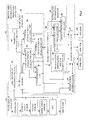
- Fig. 5 is a flow chart showing a procedure of information presentation.
- Various vehicle state amounts are inputted from the state amount detector 31 to the driving skill information presenting apparatus 30.
- the vehicle stability characteristic evaluating unit 54 calculates the vehicle stability score S v
- the turning characteristic evaluating unit 55 calculates the turning performance score T v
- the overall characteristic evaluating unit 57 calculates the overall characteristic score G based on the vehicle stability score S v and turning performance score T v . By calculating these various scores, the driver's skill evaluation for vehicle driving can be made (step S01).
- the calculated overall characteristic score G is outputted to the spare capacity determiner 44.
- the spare capacity determiner 44 determines whether the spare capacity is high or low with reference to the predetermined threshold value X 1 (step S02).
- the information presenting device selecting unit 47 instructs the information output unit 50 to output visual information (step S04).
- the presentation information amount selecting unit 46 instructs the information output unit 50 on the amount of information to be presented when the spare capacity is determined high.
- the information presenting device selecting unit 47 When the spare capacity is determined low (step S03), the information presenting device selecting unit 47, based on the determination result, instructs the information output unit 50 to output nonvisual information (step S05).
- the presentation information amount selecting unit 46 instructs the information output unit 50 on the amount of information to be presented when the spare capacity is determined low.
- the information output unit 50 acquires from the presentation information database 49 the amount of information instructed by the presentation information amount selecting unit 46. And when instructed by the information presenting device selecting unit 47 to output visual information, the information output unit 50 outputs the acquired amount of image information to the monitor 41. When instructed by the information presenting device selecting unit 47 to output nonvisual information, the information output unit 50 outputs the acquired amount of sound information to the speaker 42, or outputs the acquired amount of vibration information to the vibrator 43.
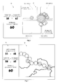
- FIG. 6 An example of image information presented by the monitor 41 is shown in Fig. 6 .
- the monitor 41 presents character information 60 and graphic information 61 relating to driving skill.
- the character information 60 shown in Fig. 6 indicates turning performance score T v , vehicle stability score S v and overall characteristic score G.
- Each score presented may be a score for each turning section Y, or may be a standardized score for a fixed period t.
- the graphic information 61 graphically displays the turning performance score T v and vehicle stability score S v .
- the display area for displaying the turning performance score T v and vehicle stability score S v is divided into four, ie a first to a fourth, areas.
- the first area is an area where the turning performance score T v is high and the vehicle stability score S v is low.
- the second area is an area where the turning performance score T v and vehicle stability score S v are both low.
- the third area is an area where the turning performance score T v is low and the vehicle stability score S v is high.
- the fourth area is an area where the turning performance score T v and vehicle stability score S v are both high.
- the first to fourth areas are classified by color.
- the turning performance score T v and vehicle stability score S v calculated for every turning section Y are plotted in a corresponding area as one circle.
- the standardized turning performance score T v and vehicle stability score S v are plotted as larger circles than the circles plotted as raw scores.
- the circles plotted in each of the first to fourth areas are displayed in a color similar to the applicable area. That is, each circle indicating a score is classified by a color of the area to which it belongs.
- Fig. 7 shows another example of image information presented on the monitor 41.
- the character information 62 shown in Fig. 7 displays, in addition to the turning performance score T v , vehicle stability score S v and overall characteristic score G, right and left maximum bank angles as numerical values indicating vehicle behavior.
- the graphic information 63 uses the information from the GPS 37, and on a road map on which the two-wheeled motor vehicle 1 has traveled, and with the turning sections Y correlated to the road map, displays evaluations of the vehicle stability score S v and turning performance score T v calculated for the applicable turning sections Y.
- Each circle displayed in the graph information 62 is classified by color as in the graphic information 61. Switching of the character information 60, 62 and the graphic information 61, 63 can be made from the input unit 26. When the driver inputs an instruction for switching to the input unit 26, a switching instruction will be made from the input unit 26 to the information output unit 50.
- image information presented may be skill evaluation results, vehicle behavior, maps and control information, for example.
- vehicle behavior presented may be bank angles, traveling speeds and suspension strokes, for example.
- Other control information presented may be throttle openings, steering angles, braking amounts and brake timing, for example. Each of these values may be presented as character information or graphic information. These pieces of information are inputted to the presentation information database.
- the sound information presented from the speaker 42 may be human voice information or may be sound information like signal sound.
- voice information When outputting in voice information, whenever each score is calculated, its result is outputted in a voice.
- voice output of the overall characteristic score G When carrying out a voice output of the overall characteristic score G, the output is made from the speaker 42 like "Your overall characteristic score G is 40 points.”
- the information output unit 50 outputs voice information corresponding to the overall characteristic score G taken from the presentation information database.
- each score When presenting sound information like signal sound from the speaker 42, each score is evaluated into levels and its level is presented in sound information. As in the determination of the spare capacity, each score is determined using threshold values for evaluating it into levels. As shown in Fig. 8 , based on predetermined threshold values X 4 and X 5 , each score is evaluated into three levels of "high”, “medium” and “low”. When the score is determined “low” which is equal to or less than the threshold value X 5 , one sound “pip" is presented. When the score is larger than the threshold value X 5 and smaller than the threshold value X 4 , two sounds “pip, pip" are presented.
- each score is evaluated into levels using threshold values as with the sound information and the level is presented in vibration information. That is, based on the predetermined threshold values X 4 and X 5 , each score is evaluated into three levels of "high”, “medium” and “low” ( Fig. 8 ). When the score is determined “low” which is equal to or less than the threshold value X 5 , vibration is presented once like “bzzz”. When the score is larger than the threshold value X 5 and smaller than the threshold value X 4 , vibration is presented twice like "bzzz, bzzz".
- vibration is presented three times like "bzzz, bzzz, bzzz". These pieces of vibration information are determined by the information output unit 50 and outputted to the vibrator 43.
- the vibrator 43 it is preferred to use what is included in one of the handlebar 5, a glove, seat 16, helmet 38, clothes worn by the driver, a cellular phone and a smart phone.
- the spare capacity is determined using the overall characteristic score G in 4.1, but the spare capacity may be determined using the vehicle stability score S v .
- Fig. 9 is a flow chart showing a procedure of information presentation by the vehicle stability score S v .
- Various vehicle state amounts are inputted from the state amount detector 31 to the driving skill information presenting apparatus 30. Based on the inputted vehicle state amounts, the vehicle stability characteristic evaluating unit 54 calculates the vehicle stability score S v . By calculating the vehicle stability score S v , the driver's skill evaluation for vehicle driving can be made (step S 11). The calculated vehicle stability score S v is outputted to the spare capacity determiner 44.
- the spare capacity determiner 44 determines whether the spare capacity is high or low with reference to a predetermined threshold value (step S12). When the spare capacity is determined high (step S 13), the information presenting device selecting unit 47, based on the determination result, instructs the information output unit 50 to output visual information (step S04). The presentation information amount selecting unit 46 instructs the information output unit 50 on the amount of information to be presented when the spare capacity is determined high.
- the information presenting device selecting unit 47 When the spare capacity is determined low (step S13), the information presenting device selecting unit 47, based on the determination result, instructs the information output unit 50 to output nonvisual information (step S05).
- the presentation information amount selecting unit 46 instructs the information output unit 50 on the amount of information to be presented when the spare capacity is determined low.
- the spare capacity is determined using only the vehicle stability score S v , the amount of information presented to the driver and the information device can be selected appropriately. Since the spare capacity is determined using only the vehicle stability score S v , information presentation can be selected easily.
- the spare capacity is determined using the overall characteristic score G in 4.1, but the spare capacity may be determined using the vehicle stability score S v and turning performance score T v .
- Fig. 10 is a flow chart showing a procedure of information presentation by the vehicle stability score S v and turning performance score T v .
- Various vehicle state amounts are inputted from the state amount detector 31 to the driving skill information presenting apparatus 30. Based on the inputted vehicle state amounts, the vehicle stability characteristic evaluating unit 54 calculates the vehicle stability score S v , and the turning characteristic evaluating unit 55 calculates the turning performance score T v . By calculating these various scores, the driver's skill evaluation for vehicle driving can be made (step S21). The calculated vehicle stability score S v and turning performance score T v are outputted to the spare capacity determiner 44.
- the spare capacity determiner 44 determines whether the spare capacity is high or low with reference to predetermined threshold values (step S22). That is, the spare capacity is determined by two references of vehicle stability and turning performance. First, the spare capacity is determined based on the vehicle stability (step S23). The spare capacity determiner 44 determines whether the vehicle stability is "high” or “low” with reference to the threshold value set beforehand for the vehicle stability score S v . When the vehicle stability is determined "low", the spare capacity is determined low.
- the spare capacity determiner 44 further determines the spare capacity with reference to the turning performance (step S24).
- the spare capacity determiner 44 determines whether the turning performance is "high” or “low” with reference to the threshold value set beforehand for the turning performance score T v .
- the turning performance is determined “high”
- the spare capacity is determined high.
- the spare capacity is determined low. That is, the spare capacity is determined high when the vehicle stability and turning performance are both determined “high”.
- the spare capacity is determined low when the vehicle stability or turning performance is determined “low”.
- the information presenting device selecting unit 47 instructs the information output unit 50 to output visual information (step S04).
- the presentation information amount selecting unit 46 instructs the information output unit 50 on the amount of information to be presented when the spare capacity is determined high.
- the information presenting device selecting unit 47 instructs the information output unit 50 to output nonvisual information (step S05).
- the presentation information amount selecting unit 46 instructs the information output unit 50 on the amount of information to be presented when the spare capacity is determined low.
- the spare capacity is determined high only when the vehicle stability score S v and turning performance score T v are both high, the amount of information to be presented to the driver and the information device are selected with increased care, and the information load on the driver is lightened.
- the spare capacity may be determined into three levels using the vehicle stability score S v and turning performance score T v .
- Fig. 11 is a flow chart showing a procedure of information presentation by the vehicle stability score S v and turning performance score T v .
- Various vehicle state amounts are inputted from the state amount detector 31 to the driving skill information presenting apparatus 30. Based on the inputted vehicle state amounts, the vehicle stability characteristic evaluating unit 54 calculates the vehicle stability score S v , and the turning characteristic evaluating unit 55 calculates the turning performance score T v . By calculating these various scores, the driver's skill evaluation for vehicle driving can be made (step S21). The calculated vehicle stability score S v and turning performance score T v are outputted to the spare capacity determiner 44.
- the spare capacity determiner 44 determines the spare capacity into three levels, ie "high”, “medium” or “low”, with reference to predetermined threshold values (step S32). That is, the spare capacity is determined into three levels by two references of the vehicle stability and turning performance. First, the spare capacity is determined based on the vehicle stability (step S33). The spare capacity determiner 44 determines whether the vehicle stability is "high” or “low” with reference to the threshold value set beforehand for the vehicle stability score S v . When the vehicle stability is determined “low”, the spare capacity is determined "low”.
- the spare capacity determiner 44 further determines the spare capacity with reference to the turning performance (step S34).
- the spare capacity determiner 44 determines whether the turning performance is "high” or "low” with reference to the threshold value set beforehand for the turning performance score T v .
- the spare capacity is determined “high”.
- the spare capacity is determined “medium”. That is, when the vehicle stability and turning performance are both determined “high”, the spare capacity is determined “high”.
- the spare capacity is determined "medium”.
- the spare capacity is determined "low”.
- the information presenting device selecting unit 47 instructs the information output unit 50 to output visual information.
- the presentation information amount selecting unit 46 instructs the information output unit 50 on the amount of detailed information to be presented when the spare capacity is determined "high” (step S35).
- visual detailed information image information having character information and graphic information is presented as shown in Figs. 6 and 7 , for example.
- the presentation area selecting unit 48 displays only areas where the stability characteristic is high among the areas displayed in the graphic information. As shown in Fig. 13 , the third area and fourth area where the stability characteristic is high are displayed and the circle representing each plotted score is displayed in enlargement.
- the information presenting device selecting unit 47 instructs the information output unit 50 to output visual information.
- the presentation information amount selecting unit 46 instructs the information output unit 50 on an amount of simplified information which should be presented when the spare capacity is determined "medium” (Step S36).
- visual simplified information as shown in Fig. 12 , for example, image information which consists of characters without graphic information is presented. The information load is lightened all the more for the omission of graphic information, to allow the driver to concentrate on driving the vehicle.
- the presentation area selecting unit 48 displays only areas where the turning characteristic is low among the areas displayed in the graphic information. As shown in Fig. 14 , the second area and third area where the turning characteristic is low are displayed and the circle representing each plotted score is displayed in enlargement.
- the information presenting device selecting unit 47 instructs the information output unit 50 to output nonvisual information.
- the presentation information amount selecting unit 46 instructs the information output unit 50 on the amount of information to be presented when the spare capacity is determined “low” (step S05).
- the nonvisual information sound information or vibration information is presented as in 4.1.
- vehicle stability score S v and turning performance score T v are used to determine the spare capacity into three levels, this is not limitative.
- a three-level determination may be made by using two threshold values with respect to each score.
- the driver can instruct from the input unit 26 which driving skill is used as reference in determining the spare capacity.
- the instruction to the input unit 26 is sent to the spare capacity determiner 44.
- the driver's spare capacity is determined based on his or her driving skill.
- a presenting device of the information on the driving skill presented to the driver and an amount of presentation information are selected according to this spare capacity.
- the driver with skill determination results fed back according to the driver's own spare capacity, can enjoy driving the vehicle at ease. Since the determination of the spare capacity is made to determine levels in a stepwise manner with reference to arbitrary threshold values, a presenting device can be selected with increased appropriateness according to the level of spare capacity. Since the information device and the amount of information presented are changed according to the driver's own spare capacity, information better suited to the driver's skill level can be presented.
Landscapes
- Engineering & Computer Science (AREA)
- Mechanical Engineering (AREA)
- Transportation (AREA)
- Automation & Control Theory (AREA)
- Chemical & Material Sciences (AREA)
- Combustion & Propulsion (AREA)
- Human Computer Interaction (AREA)
- Liquid Crystal (AREA)
- Devices For Indicating Variable Information By Combining Individual Elements (AREA)
- Control Of Driving Devices And Active Controlling Of Vehicle (AREA)
- Navigation (AREA)
Abstract
Description
- This invention relates to a driving skill information presenting apparatus for presenting information on driving skills in driving vehicles.
- Conventionally, there exist skill determining apparatus for determining the skills of drivers who drive two-wheeled vehicles or four-wheeled vehicles. In the case of a four-wheeled vehicle, the driver's skill can be determined based on steering angle. In the case of a two-wheeled vehicle, variations in the roll direction or pitch direction or caster angle are detected, in addition to variations in the yaw direction, and based on this, the driver's skill can be determined. The term "driver" includes a rider of the two-wheeled vehicle also.
- A driving support apparatus for a vehicle described in
Patent Document 1 can determine a skill level based on the driver's steering angles, and notify the driver of an improvement or degradation of the skill level. - A rider characteristic determining apparatus described in
Patent Document 2 detects variations in the roll direction or pitch direction or in the caster angle, in addition to variations in the yaw direction. Based on these detection values, it can determine the rider's vehicle stability characteristics and turning characteristics, and display results of these determinations on a monitor. -
- [Patent Document 1] Unexamined Patent Publication No.
2006-232174 - [Patent Document 2] International publication
WO2011-077638 - With the skill determining apparatus of
Patent Documents - This invention has been made having regard to the state of the art noted above, and its object is to provide a driving skill information presenting apparatus which changes presented information according to the driver's driving skill.
- To fulfill the above object, this invention provides the following construction.
- A driving skill information presenting apparatus according to this invention comprises a driving skill evaluator for evaluating a driver's driving skill; a spare capacity determiner for determining the driver's spare capacity for driving based on the driving skill; a presentation information selector for selecting presentation information on the driving skill based on the spare capacity; and an information output unit for outputting the presentation information selected.
- According to the driving skill information presenting apparatus of this invention, the driving skill evaluator evaluates the driver's driving skill. Based on the driving skill evaluated, the spare capacity determiner determines a spare capacity indicating how much composure the driver has in driving. Based on the spare capacity determined, the presentation information selector selects information on the driving skill to be presented to the driver. The selected skill information is outputted from the information output unit. Since the skill information to be presented is selected according to the driver's spare capacity for driving, the driver can be presented with the skill information with an appropriate information load. Presented with skill information suited to his or her own driving skill, the driver can enjoy driving the vehicle at ease without feeling stress in acquiring the skill information.
- It is preferred that the spare capacity determiner determines the spare capacity stepwise according to the driving skill. With the spare capacity determiner determining the spare capacity stepwise according to the driver's driving skill, skill information can be presented with increased appropriateness according to each level of the stepwise determination. The driver, with the presented skill information variable according to the driver's own spare capacity level, can enjoy driving the vehicle at ease. Since his or her own skill level can be recognized, the driver can drive the vehicle in a way appropriate to his or her skill level.
- It is preferred that the presentation information selector includes an output device selecting unit for selecting one of visual information and nonvisual information as the presentation information according to the spare capacity. The output device selecting unit selects visual information or nonvisual information as the presentation information according to the spare capacity. Consequently, the driver can obtain visual information or nonvisual information according to his or her own spare capacity, thereby to obtain an appropriate information load.
- It is preferred that the presentation information selector includes a presentation area selecting unit for selecting presentation areas for the visual information according to the spare capacity. Since the presentation area selecting unit selects presentation areas for the visual information according to the spare capacity, the driver can obtain visual information in the presentation areas according to his or her own spare capacity, and this facilitates acquisition of skill information.
- It is preferred that the nonvisual information is one of sound information and vibration information. Since the nonvisual information is sound information or vibration information, the driver's information load is lightened to allow the driver to enjoy driving at ease.
- It is preferred that the presentation information selector includes a presentation information amount selecting unit for selecting an information amount of the presentation information according to the spare capacity. Since the presentation information amount selecting unit selects an information amount of the presentation information according to the spare capacity, the driver, with the amount of information varied according to his or her own spare capacity, can obtain an appropriate information load.
- This invention can provide a driving skill information presenting apparatus which changes presented information according to the driver's driving skill.
-
-
Figure 1 is a side view showing an outline construction of a two-wheeled motor vehicle according to an embodiment; -
Figure 2 is a functional block diagram showing a construction of a driving skill information presenting apparatus according to the embodiment; -
Figure 3 is an explanatory view showing spare capacity determination according to the embodiment; -
Figure 4 is an explanatory view showing spare capacity determination according to the embodiment; -
Figure 5 is a flow chart showing a procedure of information presentation according to the embodiment; -
Figure 6 is an explanatory view showing visual information presented according to the embodiment; -
Figure 7 is an explanatory view showing visual information presented according to the embodiment; -
Figure 8 is an explanatory view showing a staged presentation of skill information by nonvisual information according to the embodiment; -
Figure 9 is a flow chart showing a procedure of information presentation according to the embodiment; -
Figure 10 is a flow chart showing a procedure of information presentation according to the embodiment; -
Figure 11 is a flow chart showing a procedure of information presentation according to the embodiment; -
Figure 12 is an explanatory view showing visual information presented according to the embodiment; -
Figure 13 is an explanatory view showing visual information presented according to the embodiment; and -
Figure 14 is an explanatory view showing visual information presented according to the embodiment; - An embodiment of this invention will be described hereinafter with reference to the drawings. Here, a two-wheeled motor vehicle will be described as an example of vehicle according to the embodiment. In the following description, front and rear and right and left are based on a traveling direction of the two-wheeled motor vehicle.
-
Fig. 1 is a side view showing an outline construction of a two-wheeled motor vehicle having a driving skill information presenting apparatus according to this embodiment. The two-wheeledmotor vehicle 1 has amain frame 2. A head tube 3 is provided at an upper front end of themain frame 2. A steeringshaft 4 is inserted in the head tube 3. A handlebar 5 is connected to the upper end of thesteering shaft 4. A brake lever (not shown) is disposed on a right-hand side of the handlebar 5. - A pair of extendible and contractible front forks 7 are connected to the lower end of the
steering shaft 4. Thus, the front forks 7 are swingable by turning operation of the handlebar 5. Afront wheel 8 is rotatably attached to lower ends of the front forks 7. Vibration of thefront wheel 8 is absorbed by expansion and contraction of the front forks 7.Brakes 10 are attached to the lower ends of the front forks 7 for braking rotation of thefront wheel 8 by operation of the brake lever. Afront wheel cover 11 is fixed to the front forks 7 above thefront wheel 8. - A
fuel tank 15 and aseat 16 are supported as arranged fore and aft on an upper portion of themain frame 2. Anengine 17 and aspeed changer 18 are held by themain frame 2 in a position below thefuel tank 15. Thespeed changer 18 has adrive shaft 19 for outputting power generated by theengine 17. Adrive sprocket 20 is connected to thedrive shaft 19. - A
swing arm 21 is swingably supported by a lower rearward portion of themain frame 2. A drivensprocket 22 and arear wheel 23 are rotatably supported by a rear end portion of theswing arm 21. Achain 24 is provided to extend between thedrive sprocket 20 and the drivensprocket 22. The power generated by theengine 17 is transmitted to therear wheel 23 through thespeed changer 18,drive shaft 19,drive sprocket 20,chain 24, and drivensprocket 22. An ECU (Electronic Control Unit) 25 is provided below theseat 16 for controlling operation of various components of the two-wheeledmotor vehicle 1. - The two-wheeled
motor vehicle 1 has astate amount detector 31 for detecting traveling states of the vehicle. Thestate amount detector 31 includes agyroscope 33, asteering angle sensor 34, astroke sensor 35, awheel speed sensor 36 provided for thefront wheel 8, and a GPS (Global Positioning System) 37 for measuring a position of the two-wheeledmotor vehicle 1. - The
gyroscope 33 is mounted on thefuel tank 15. Thegyroscope 33 detects angular speeds and angles in triaxial directions of yaw, roll and pitch of the two-wheeledmotor vehicle 1. That is, it detects a yaw rate, a yaw angle, a roll rate, a roll angle, a pitch rate and a pitch angle of the two-wheeledmotor vehicle 1. Thesteering angle sensor 34 is provided at the upper end of the front forks 7 for detecting a steering angle which is a rotation angle of thesteering shaft 4. - The
stroke sensor 35 is provided on the front forks 7 for detecting amounts of expansion and contraction of the front forks 7. Further, it calculates caster angles of the front forks 7 based on these amounts of expansion and contraction. When the front forks 7 are expanded and contracted by a hydraulic suspension, the stroke sensor 7 may calculate the caster angles by detecting a hydraulic pressure of the suspension. Thewheel speed sensor 36 detects rotating speeds of thefront wheel 8. Further, it calculates vehicle speeds of the two-wheeledmotor vehicle 1 based on these rotating speeds. TheGPS 37 is disposed forward of thefuel tank 15, and detects position information of the two-wheeledmotor vehicle 1. - When the driver steers the handlebar 5 of the two-wheeled
motor vehicle 1 in going around a curve, the yaw angle, yaw rate and steering angle of the two-wheeledmotor vehicle 1 will change. When the driver leans the vehicle body of the two-wheeledmotor vehicle 1 toward the center of the curve, the roll angle and roll rate of the two-wheeledmotor vehicle 1 will change. When the driver operates the brake lever to slow down the two-wheeledmotor vehicle 1 before entering the curve or during curve running, the front forks 7 will contract. This contraction of the front forks 7 will change the pitch angle, pitch rate and caster angle of the two-wheeledmotor vehicle 1. - These yaw angle, yaw rate, roll angle, roll rate, pitch angle, pitch rate, caster angle, steering angle, vehicle speed and position information of the two-wheeled
motor vehicle 1 are called vehicle state amounts. - The two-wheeled
motor vehicle 1 further includes amonitor 41 for displaying road information and evaluation results of driving skill, aradio transceiver 40 for communicating information between the two-wheeledmotor vehicle 1 and a helmet, and avibrator 43 for communicating the evaluation results of driving skill by vibration. Themonitor 41 is installed forward of the handlebar 5. Thevibrator 43 is embedded in theseat 16. Aninput unit 26 having buttons for enabling key input is disposed adjacent themonitor 41. The driver can switch image information displayed on themonitor 41 from theinput unit 26. - The
helmet 38 worn by the driver has a radio transceiver 39 for communicating information between the two-wheeledmotor vehicle 1 and the helmet 39, and aspeaker 42 for outputting sound information communicated by radio. The two-wheeledmotor vehicle 1 may have a mobile terminal such as a smartphone installed in place of themonitor 41, and a headphone in place of thespeaker 42. The information communication from the two-wheeledmotor vehicle 1 to the smartphone is outputted from theradio transceiver 40. - Next, the construction of driving skill
information presenting apparatus 30 will be described with reference toFigs. 1 and2. Fig. 2 is a functional block diagram showing the construction of the driving skill information presenting apparatus. The driving skillinformation presenting apparatus 30 is formed of a CPU and memory, and may be installed as part ofECU 25. The driving skillinformation presenting apparatus 30 includes a drivingskill evaluator 32, aspare capacity determiner 44, apresentation information selector 45, apresentation information database 49 and aninformation output unit 50. - The driving
skill evaluator 32 evaluates the driving skill of the driver. The drivingskill evaluator 32 includes amemory 51, a turningmovement discriminating unit 52, acomponent separating unit 53, a vehicle stabilitycharacteristic evaluating unit 54, a turning characteristic evaluatingunit 55, a standardizingunit 56 and an overallcharacteristic evaluating unit 57. Thegyroscope 33, steeringangle sensor 34,stroke sensor 35,wheel speed sensor 36 andGPS 37 are connected to inputs of the drivingskill evaluator unit 32. Each vehicle state amount detected by thestate amount detector 31 is inputted to the drivingskill evaluator 32, and is stored in time series in thememory 51. - The turning
movement discriminating unit 52 discriminates whether the two-wheeledmotor vehicle 1 has carried out a turning movement, which is taken into account in determining the driver's skill evaluation. Here, a criterion for determining a turning movement will be described taking for example a case where the yaw rate of the two-wheeledmotor vehicle 1 has at least a certain fixed value, and this continues for at least a certain fixed time. When the above conditions are not met, the turningmovement discriminating unit 52 does not determine that the two-wheeledmotor vehicle 1 has carried out a turning movement. - The turning
movement discriminating unit 52 discriminates a turning movement section Y from absolute values of the detection values of the yaw rate inputted from thegyroscope 33. That is, if a section is from a point of time when the absolute values of detection values of the yaw rate of the two-wheeledmotor vehicle 1 exceed a threshold Xt to a point of time when they fall below the threshold Xt again, and if a duration of this section is at least a minimum duration Ymin, the turningmovement discriminating unit 52 will discriminate this section to be a turning movement section Y. When the section from the point of time when the detection values of the yaw rate of the two-wheeledmotor vehicle 1 exceed the threshold Xt to the point of time when they fall below the threshold Xt again is less than the minimum duration Ymin, the turningmovement discriminating unit 52 will not discriminate this section to be a turning movement section. The value of threshold Xt may be set as appropriate according to the type of the two-wheeledmotor vehicle 1. Although the above is a method of discriminating the turning movement section Y using the yaw rate, the turning movement section Y may be discriminated using other methods. - When the turning
movement discriminating unit 52 discriminates the turning movement section Y, the detection value of each vehicle state amount stored in thememory 51 during the turning movement section Y is sent to thecomponent separating unit 53. Thecomponent separating unit 53 is formed of a lowpass filter and a bandpass filter. Each detection value inputted to thecomponent separating unit 53 is put to filtering by the lowpass filter and bandpass filter. The vehicle state amounts whose components are separable by thecomponent separating unit 53 include yaw rate, yaw angle, roll rate, roll angle, pitch rate, pitch angle, steering angle, and caster angle. The component separation by filtering will be described taking the roll rate for example. - Entire frequency band data of the roll rate inputted to the
component separating unit 53 is subjected to filtering by the lowpass filter and bandpass filter. The lowpass filter removes high-frequency components higher than a threshold frequency Fc1 which is a value set beforehand. Consequently, low-frequency components are outputted from the lowpass filter. The bandpass filter removes low-frequency components equal to or lower than the threshold frequency Fc1, and removes noise components equal to or higher than a threshold frequency Fc2. Consequently, high-frequency band components 73 are outputted from the bandpass filter 66. Since frequency components equal to or higher than the threshold frequency Fc2 are noise components, they are irrelevant to the driver's characteristic determination. - As a result of the time series data of each detection value stored in the
memory 51 put to the filtering by the lowpass filter and bandpass filter, each detection value is separated into low-frequency band components and high-frequency band components. The threshold frequency Fc1 may be set according to the characteristics to determine. When determining the driver's characteristics, for example, the threshold frequency Fc1 may be set so that the difference between beginner and experienced person may be a maximum. However, the threshold frequency Fc2 must certainly be a larger value than the threshold frequency Fc1. - The vehicle stability
characteristic evaluating unit 54 receives each detection value in the turning movement section Y of the two-wheeledmotor vehicle 1 filtered by thelowpass filter 65 and bandpass filter 66. Here, the yaw rate, roll rate and pitch rate are inputted by way of example. - The low-frequency band of each rate separated by the threshold frequency Fc1 is interpreted as prediction components for the driver making a turn around a curve. The high-frequency band is interpreted as adjustment components adjusted when the driver turned around a curve. Next, for each of the yaw rate, roll rate and pitch rate, average values of integral values per unit time of the prediction components and adjustment components of each rate in the turning section Y are calculated. Values obtained by dividing the values derived corresponding to the respective prediction components by values corresponding to the adjustment components are regarded as stability indexes (Syaw, Sroll, Spitch) of the yaw rate, roll rate and pitch rate in one turning section Y.
- When the driver performs smooth handlebar control relative to a curve, an integral quantity of absolute values of the low-frequency band becomes large, and an integral quantity of absolute values of the high-frequency band becomes small. When the driver carries out fine control of the handlebar 5 for adjustment during curve running, the integral quantity of absolute values of the high-frequency band will become large, and the integral quantity of absolute values of the low-frequency band will become that much smaller. Thus, by using as an index the ratio between the integral quantity of absolute values of the low-frequency band and the integral quantity of absolute values of the high-frequency band, the driver's characteristics during curve running can be expressed by scores.
- Thus, the vehicle stability indexes of the two-wheeled
motor vehicle 1 can be calculated by obtaining ratios between the integral quantity of absolute values of the low-frequency band and the high-frequency band of the yaw rate, roll rate and pitch rate during turning movement of the two-wheeledmotor vehicle 1. Further, a vehicle stability score Sv which is a weighted linear sum of the above-mentioned three stability indexes (Syaw, Sroll, Spitch) is calculated. The vehicle stability score Sv calculated is outputted to thespare capacity determiner 44,presentation information database 49, standardizingunit 56 and overall characteristic evaluatingunit 57. - The turning characteristic evaluating
unit 55 receives each detection value in the turning movement section Y of the two-wheeledmotor vehicle 1 filtered by the lowpass filter. Here, the steering angle, roll angle, and pitch angle or caster angle are inputted by way of example. Vehicle speeds in the turning movement section Y of the two-wheeledmotor vehicle 1 are inputted from thememory 51 to the turning characteristic evaluatingunit 55. - The low-frequency band of each angle is interpreted as prediction components of the driver turning the curve. When the driver performs smooth handlebar control relative to the curve, the quantity of absolute values of the low-frequency band is large. Different values for various types of angle may be used as the threshold frequency Fc1 used in the frequency separation of each rate. An average value of integral values per unit time of the prediction components in the turning section Y is calculated for each angle of the steering angle, roll angle, and pitch or caster angle. The calculated values are regarded as turning performance indexes Tsteer, Troll, Tpitch(caster) of the steering angle, roll angle, and pitch or caster angle.
- An average vehicle speed Tspeed in the turning section Y is calculated from the inputted vehicle speeds of the turning section Y. A weighted linear sum of these three turning performance indexes and the average vehicle speed is calculated as a turning performance score Tv. The turning performance score Tv is outputted to the
spare capacity determiner 44,presentation information database 49, standardizingunit 56 and overall characteristic evaluatingunit 57. - The overall
characteristic evaluating unit 57 obtains the driver's overall characteristic score G for the turning section Y by calculating a weighted linear sum of vehicle stability score Sv and turning performance score Tv. The overall characteristic score G comprehensively evaluates the driver's characteristics based on the driver's vehicle stability characteristic and turning characteristic. - With the above, the driver's driving skill can be evaluated from the three indexes of overall characteristic score G, vehicle stability score Sv and turning performance score Tv. Since the respective scores are continuous values, the driver's vehicle stability, turning performance and overall characteristics can be evaluated steplessly by the respective scores. Apart from using the calculated respective scores as they are for evaluation, the driver's driving skill can be evaluated by a score standardizing each score.
- The standardizing
unit 56 calculates each average score for every fixed period based on each of the overall characteristic score G, vehicle stability score Sv and turning performance score Tv.Fig. 3 is a graph plotting in time series certain scores calculated for each turning section Y. An average score may be calculated for each given period t based on a plurality of calculated scores, and an average score may be calculated for a certain number of turning sections. Apart from average scores, standard deviations may be calculated for evaluation. Each standardized score is sent to thespare capacity determiner 44 andpresentation information database 49. - Next, the driver's spare capacity for driving is determined based on each score which evaluates a driving characteristic. Depending on this spare capacity determined, a device for presenting skill information of the driver and an amount of information are selected appropriately. The
spare capacity determiner 44 may determine the spare capacity only with reference to the overall characteristic score G or the vehicle stability score Sv, or may determine the spare capacity based on at least two scores among the overall characteristic score G, vehicle stability score Sv and turning performance score Tv. A case of determining the spare capacity based on the overall characteristic score G will be described by way of example. - The
spare capacity determiner 44 determines the driver's spare capacity for driving based on the overall characteristic score G. That is, as shown inFig. 3 , based on a predetermined threshold value X1 for the overall characteristic score G, a spare capacity is determined into two levels, ie "high" or "low". Alternatively, as shown inFig. 4 , based on two predetermined threshold values X2 and X3, a spare capacity may be determined into three levels of "high", "medium" and "low". The overall characteristic score G may be a score sent from the overallcharacteristic evaluating unit 57, or a standardized score sent from the standardizingunit 56. A determination result of the spare capacity is outputted to thepresentation information selector 45. - The
presentation information selector 45 includes a presentation informationamount selecting unit 46, an information presentingdevice selecting unit 47 and a presentationarea selecting unit 48. In response to the determination result of the spare capacity, thepresentation information selector 45 selects an information device for presentation to the driver and an amount of information. - The presentation information
amount selecting unit 46 selects an amount of information presented according to the determination result of the spare capacity. When, for example, the determination result of the spare capacity is "high" of the two-level evaluation, information relating to the overall characteristic score G, vehicle stability score Sv and turning performance score Tv is selected. When the determination result of the spare capacity is "low" of the two-level evaluation, only information relating to the overall characteristic score G is selected. - The information presenting
device selecting unit 47 selects a presenting means, ie a presenting device, of skill information according to the determination result of the spare capacity. In this embodiment, themonitor 41,speaker 42 andvibrator 43 are installed as information presenting devices. When the determination result of the spare capacity is "high" of the two-level evaluation, visual information is selected as presenting means, and themonitor 41 is selected as visual information presenting device. When the determination result of the spare capacity is "low" of the two-level evaluation, nonvisual information is selected as presenting means, and either thespeaker 42 or thevibrator 43 is selected as nonvisual information presenting device. - When the presentation of visual information is selected by the information presenting
device selecting unit 47, the presentationarea selecting unit 48 will select areas for displaying skill information according to the determination result of the spare capacity. The display areas may be selected according to the determination result of the spare capacity, an enlarged display may be made to display a score of an arbitrary rate, or an auto scale change may be made centering on the center of gravity of the score displayed. - The
presentation information database 49 is formed of a memory storing all information that can be presented to the driver. In addition to each vehicle state amount detected by thestate amount detector 31, each score evaluated for every turning section Y by the drivingskill evaluator 32 is also stored. Sound information which is nonvisual information is also stored. Thepresentation information database 49 andmemory 51 may be integrated. - The
information output unit 50 fetches, from the presentation information database, skill information applicable to the amount of presentation information selected by the presentation informationamount selecting unit 46, and outputs the fetched skill information so that it can be presented from the information presenting device selected by the information presentingdevice selecting unit 47. That is, theinformation output unit 50 will, in the amount of presentation information selected by the presentation informationamount selecting unit 46, output image information when themonitor 41 is selected by the information presentingdevice selecting unit 47, output sound information when thespeaker 42 is selected, and output vibration information when thevibrator 43 is selected. - Next, an operation to present information with the overall characteristic evaluation serving as a reference for spare capacity determination in the embodiment will be described with reference to
Fig. 5. Fig. 5 is a flow chart showing a procedure of information presentation. - Various vehicle state amounts are inputted from the
state amount detector 31 to the driving skillinformation presenting apparatus 30. Based on the inputted vehicle state amounts, the vehicle stabilitycharacteristic evaluating unit 54 calculates the vehicle stability score Sv, and the turning characteristic evaluatingunit 55 calculates the turning performance score Tv. The overallcharacteristic evaluating unit 57 calculates the overall characteristic score G based on the vehicle stability score Sv and turning performance score Tv. By calculating these various scores, the driver's skill evaluation for vehicle driving can be made (step S01). The calculated overall characteristic score G is outputted to thespare capacity determiner 44. - In response to the inputted overall characteristic score G, the
spare capacity determiner 44 determines whether the spare capacity is high or low with reference to the predetermined threshold value X1 (step S02). When the spare capacity is determined high (step S03), the information presentingdevice selecting unit 47, based on the determination result, instructs theinformation output unit 50 to output visual information (step S04). The presentation informationamount selecting unit 46 instructs theinformation output unit 50 on the amount of information to be presented when the spare capacity is determined high. - When the spare capacity is determined low (step S03), the information presenting
device selecting unit 47, based on the determination result, instructs theinformation output unit 50 to output nonvisual information (step S05). The presentation informationamount selecting unit 46 instructs theinformation output unit 50 on the amount of information to be presented when the spare capacity is determined low. - The
information output unit 50 acquires from thepresentation information database 49 the amount of information instructed by the presentation informationamount selecting unit 46. And when instructed by the information presentingdevice selecting unit 47 to output visual information, theinformation output unit 50 outputs the acquired amount of image information to themonitor 41. When instructed by the information presentingdevice selecting unit 47 to output nonvisual information, theinformation output unit 50 outputs the acquired amount of sound information to thespeaker 42, or outputs the acquired amount of vibration information to thevibrator 43. - An example of image information presented by the
monitor 41 is shown inFig. 6 . As shown inFig. 6 , themonitor 41presents character information 60 andgraphic information 61 relating to driving skill. Thecharacter information 60 shown inFig. 6 indicates turning performance score Tv, vehicle stability score Sv and overall characteristic score G. Each score presented may be a score for each turning section Y, or may be a standardized score for a fixed period t. - The
graphic information 61 graphically displays the turning performance score Tv and vehicle stability score Sv. The display area for displaying the turning performance score Tv and vehicle stability score Sv is divided into four, ie a first to a fourth, areas. The first area is an area where the turning performance score Tv is high and the vehicle stability score Sv is low. The second area is an area where the turning performance score Tv and vehicle stability score Sv are both low. The third area is an area where the turning performance score Tv is low and the vehicle stability score Sv is high. The fourth area is an area where the turning performance score Tv and vehicle stability score Sv are both high. The first to fourth areas are classified by color. The turning performance score Tv and vehicle stability score Sv calculated for every turning section Y are plotted in a corresponding area as one circle. The standardized turning performance score Tv and vehicle stability score Sv are plotted as larger circles than the circles plotted as raw scores. The circles plotted in each of the first to fourth areas are displayed in a color similar to the applicable area. That is, each circle indicating a score is classified by a color of the area to which it belongs. -
Fig. 7 shows another example of image information presented on themonitor 41. Thecharacter information 62 shown inFig. 7 displays, in addition to the turning performance score Tv, vehicle stability score Sv and overall characteristic score G, right and left maximum bank angles as numerical values indicating vehicle behavior. Thegraphic information 63, using the information from theGPS 37, and on a road map on which the two-wheeledmotor vehicle 1 has traveled, and with the turning sections Y correlated to the road map, displays evaluations of the vehicle stability score Sv and turning performance score Tv calculated for the applicable turning sections Y. Each circle displayed in thegraph information 62 is classified by color as in thegraphic information 61. Switching of thecharacter information graphic information input unit 26. When the driver inputs an instruction for switching to theinput unit 26, a switching instruction will be made from theinput unit 26 to theinformation output unit 50. - Other image information presented may be skill evaluation results, vehicle behavior, maps and control information, for example. Other vehicle behavior presented may be bank angles, traveling speeds and suspension strokes, for example. Other control information presented may be throttle openings, steering angles, braking amounts and brake timing, for example. Each of these values may be presented as character information or graphic information. These pieces of information are inputted to the presentation information database.
- Next, an example of sound information presented from the
speaker 42 will be described. The sound information presented from thespeaker 42 may be human voice information or may be sound information like signal sound. When outputting in voice information, whenever each score is calculated, its result is outputted in a voice. When carrying out a voice output of the overall characteristic score G, the output is made from thespeaker 42 like "Your overall characteristic score G is 40 points." Theinformation output unit 50 outputs voice information corresponding to the overall characteristic score G taken from the presentation information database. - When presenting sound information like signal sound from the
speaker 42, each score is evaluated into levels and its level is presented in sound information. As in the determination of the spare capacity, each score is determined using threshold values for evaluating it into levels. As shown inFig. 8 , based on predetermined threshold values X4 and X5, each score is evaluated into three levels of "high", "medium" and "low". When the score is determined "low" which is equal to or less than the threshold value X5, one sound "pip" is presented. When the score is larger than the threshold value X5 and smaller than the threshold value X4, two sounds "pip, pip" are presented. When the score is larger than the threshold value X5, three sounds "pip, pip, pip" are presented. These pieces of sound information are determined by theinformation output unit 50, and corresponding sound information is taken out of the presentation information database, and is outputted to thespeaker 42. - Next, an example of vibration information presented from the
vibrator 43 will be described. With the vibration information presented from thevibrator 43, whenever each score is calculated, its result is evaluated into levels using threshold values as with the sound information and the level is presented in vibration information. That is, based on the predetermined threshold values X4 and X5, each score is evaluated into three levels of "high", "medium" and "low" (Fig. 8 ). When the score is determined "low" which is equal to or less than the threshold value X5, vibration is presented once like "bzzz". When the score is larger than the threshold value X5 and smaller than the threshold value X4, vibration is presented twice like "bzzz, bzzz". When the score is larger than the threshold value X5, vibration is presented three times like "bzzz, bzzz, bzzz". These pieces of vibration information are determined by theinformation output unit 50 and outputted to thevibrator 43. As thevibrator 43, it is preferred to use what is included in one of the handlebar 5, a glove,seat 16,helmet 38, clothes worn by the driver, a cellular phone and a smart phone. - The spare capacity is determined using the overall characteristic score G in 4.1, but the spare capacity may be determined using the vehicle stability score Sv.
Fig. 9 is a flow chart showing a procedure of information presentation by the vehicle stability score Sv. - Various vehicle state amounts are inputted from the
state amount detector 31 to the driving skillinformation presenting apparatus 30. Based on the inputted vehicle state amounts, the vehicle stabilitycharacteristic evaluating unit 54 calculates the vehicle stability score Sv. By calculating the vehicle stability score Sv, the driver's skill evaluation for vehicle driving can be made (step S 11). The calculated vehicle stability score Sv is outputted to thespare capacity determiner 44. - In response to the inputted vehicle stability score Sv, the
spare capacity determiner 44 determines whether the spare capacity is high or low with reference to a predetermined threshold value (step S12). When the spare capacity is determined high (step S 13), the information presentingdevice selecting unit 47, based on the determination result, instructs theinformation output unit 50 to output visual information (step S04). The presentation informationamount selecting unit 46 instructs theinformation output unit 50 on the amount of information to be presented when the spare capacity is determined high. - When the spare capacity is determined low (step S13), the information presenting
device selecting unit 47, based on the determination result, instructs theinformation output unit 50 to output nonvisual information (step S05). The presentation informationamount selecting unit 46 instructs theinformation output unit 50 on the amount of information to be presented when the spare capacity is determined low. - As described above, also when the spare capacity is determined using only the vehicle stability score Sv, the amount of information presented to the driver and the information device can be selected appropriately. Since the spare capacity is determined using only the vehicle stability score Sv, information presentation can be selected easily.
- The spare capacity is determined using the overall characteristic score G in 4.1, but the spare capacity may be determined using the vehicle stability score Sv and turning performance score Tv.
Fig. 10 is a flow chart showing a procedure of information presentation by the vehicle stability score Sv and turning performance score Tv. - Various vehicle state amounts are inputted from the
state amount detector 31 to the driving skillinformation presenting apparatus 30. Based on the inputted vehicle state amounts, the vehicle stabilitycharacteristic evaluating unit 54 calculates the vehicle stability score Sv, and the turning characteristic evaluatingunit 55 calculates the turning performance score Tv. By calculating these various scores, the driver's skill evaluation for vehicle driving can be made (step S21). The calculated vehicle stability score Sv and turning performance score Tv are outputted to thespare capacity determiner 44. - In response to the inputted vehicle stability score Sv and turning performance score Tv, the
spare capacity determiner 44 determines whether the spare capacity is high or low with reference to predetermined threshold values (step S22). That is, the spare capacity is determined by two references of vehicle stability and turning performance. First, the spare capacity is determined based on the vehicle stability (step S23). Thespare capacity determiner 44 determines whether the vehicle stability is "high" or "low" with reference to the threshold value set beforehand for the vehicle stability score Sv. When the vehicle stability is determined "low", the spare capacity is determined low. - When the vehicle stability is determined "high", the
spare capacity determiner 44 further determines the spare capacity with reference to the turning performance (step S24). Thespare capacity determiner 44 determines whether the turning performance is "high" or "low" with reference to the threshold value set beforehand for the turning performance score Tv. When the turning performance is determined "high", the spare capacity is determined high. When the turning performance is determined "low", the spare capacity is determined low. That is, the spare capacity is determined high when the vehicle stability and turning performance are both determined "high". The spare capacity is determined low when the vehicle stability or turning performance is determined "low". - When the spare capacity is determined high, the information presenting
device selecting unit 47 instructs theinformation output unit 50 to output visual information (step S04). The presentation informationamount selecting unit 46 instructs theinformation output unit 50 on the amount of information to be presented when the spare capacity is determined high. When the spare capacity is determined low, the information presentingdevice selecting unit 47 instructs theinformation output unit 50 to output nonvisual information (step S05). The presentation informationamount selecting unit 46 instructs theinformation output unit 50 on the amount of information to be presented when the spare capacity is determined low. - As described above, since the spare capacity is determined high only when the vehicle stability score Sv and turning performance score Tv are both high, the amount of information to be presented to the driver and the information device are selected with increased care, and the information load on the driver is lightened.
- The spare capacity may be determined into three levels using the vehicle stability score Sv and turning performance score Tv.
Fig. 11 is a flow chart showing a procedure of information presentation by the vehicle stability score Sv and turning performance score Tv. - Various vehicle state amounts are inputted from the
state amount detector 31 to the driving skillinformation presenting apparatus 30. Based on the inputted vehicle state amounts, the vehicle stabilitycharacteristic evaluating unit 54 calculates the vehicle stability score Sv, and the turning characteristic evaluatingunit 55 calculates the turning performance score Tv. By calculating these various scores, the driver's skill evaluation for vehicle driving can be made (step S21). The calculated vehicle stability score Sv and turning performance score Tv are outputted to thespare capacity determiner 44. - In response to the inputted vehicle stability score Sv and turning performance score Tv, the
spare capacity determiner 44 determines the spare capacity into three levels, ie "high", "medium" or "low", with reference to predetermined threshold values (step S32). That is, the spare capacity is determined into three levels by two references of the vehicle stability and turning performance. First, the spare capacity is determined based on the vehicle stability (step S33). Thespare capacity determiner 44 determines whether the vehicle stability is "high" or "low" with reference to the threshold value set beforehand for the vehicle stability score Sv. When the vehicle stability is determined "low", the spare capacity is determined "low". - When the vehicle stability is determined "high", the
spare capacity determiner 44 further determines the spare capacity with reference to the turning performance (step S34). Thespare capacity determiner 44 determines whether the turning performance is "high" or "low" with reference to the threshold value set beforehand for the turning performance score Tv. When the turning performance is determined "high", the spare capacity is determined "high". When the turning performance is determined "low", the spare capacity is determined "medium". That is, when the vehicle stability and turning performance are both determined "high", the spare capacity is determined "high". When the vehicle stability is determined "high" and the turning performance is determined "low", the spare capacity is determined "medium". When the vehicle stability and turning performance are both determined "low", the spare capacity is determined "low". - When the spare capacity is determined "high", the information presenting
device selecting unit 47 instructs theinformation output unit 50 to output visual information. The presentation informationamount selecting unit 46 instructs theinformation output unit 50 on the amount of detailed information to be presented when the spare capacity is determined "high" (step S35). As visual detailed information, image information having character information and graphic information is presented as shown inFigs. 6 and 7 , for example. - When the spare capacity is determined "high", the presentation
area selecting unit 48 displays only areas where the stability characteristic is high among the areas displayed in the graphic information. As shown inFig. 13 , the third area and fourth area where the stability characteristic is high are displayed and the circle representing each plotted score is displayed in enlargement. - When the spare capacity is determined "medium", the information presenting
device selecting unit 47 instructs theinformation output unit 50 to output visual information. The presentation informationamount selecting unit 46 instructs theinformation output unit 50 on an amount of simplified information which should be presented when the spare capacity is determined "medium" (Step S36). As visual simplified information, as shown inFig. 12 , for example, image information which consists of characters without graphic information is presented. The information load is lightened all the more for the omission of graphic information, to allow the driver to concentrate on driving the vehicle. - When the spare capacity is determined "medium", the presentation
area selecting unit 48 displays only areas where the turning characteristic is low among the areas displayed in the graphic information. As shown inFig. 14 , the second area and third area where the turning characteristic is low are displayed and the circle representing each plotted score is displayed in enlargement. - When the spare capacity is determined "low", the information presenting
device selecting unit 47 instructs theinformation output unit 50 to output nonvisual information. The presentation informationamount selecting unit 46 instructs theinformation output unit 50 on the amount of information to be presented when the spare capacity is determined "low" (step S05). As the nonvisual information, sound information or vibration information is presented as in 4.1. - Although the vehicle stability score Sv and turning performance score Tv are used to determine the spare capacity into three levels, this is not limitative. A three-level determination may be made by using two threshold values with respect to each score. The driver can instruct from the
input unit 26 which driving skill is used as reference in determining the spare capacity. The instruction to theinput unit 26 is sent to thespare capacity determiner 44. - According to this embodiment, the driver's spare capacity is determined based on his or her driving skill. A presenting device of the information on the driving skill presented to the driver and an amount of presentation information are selected according to this spare capacity. The driver, with skill determination results fed back according to the driver's own spare capacity, can enjoy driving the vehicle at ease. Since the determination of the spare capacity is made to determine levels in a stepwise manner with reference to arbitrary threshold values, a presenting device can be selected with increased appropriateness according to the level of spare capacity. Since the information device and the amount of information presented are changed according to the driver's own spare capacity, information better suited to the driver's skill level can be presented.
- When the spare capacity is determined "low", skill information is fed back to the driver in sound information or vibration information which does not impose a visual load. When the spare capacity is determined "high", skill information in a visually large amount of information is fed back. The driver, when skill information is fed back in sound or vibration which is small in the amount of information, will feel unsatisfied. This produces a desire to improve skill and know more detailed information, which leads to motivational leverage for improving skill. On the other hand, when detailed skill information is fed back in image information, the driver, who can know the detailed information at a time when he or she wants to know it, can enjoy improving the driving skill.
- This invention is not limited to the foregoing embodiment, but may be modified as follows:
- (1) In the foregoing embodiment, the two-wheeled
motor vehicle 1 is described as an example of vehicles, but this is not limitative. The driving skill information presenting apparatus may be used on a four-wheeled vehicle. - (2) The
state amount detector 31 may acquire detection values representing vehicle states other than yaw angle, yaw rate, roll angle, roll rate, pitch angle, pitch rate, caster angle, steering angle, vehicle speed and position information, or may detect only arbitrary detection values among the above vehicle state amounts. -
- 1
- two-wheeled motor vehicle
- 30
- driving skill information presenting apparatus
- 32
- driving skill evaluator
- 44
- spare capacity determiner
- 45
- presentation information selector
- 46
- presentation information amount selecting unit
- 47
- information presenting device selecting unit
- 48
- presentation area selecting unit
- 50
- information output unit
- 54
- vehicle stability characteristic evaluating unit
- 55
- turning characteristic evaluating unit
- 57
- overall characteristic evaluating unit
Claims (6)
- A driving skill information presenting apparatus comprising:a driving skill evaluator for evaluating a driver's driving skill;a spare capacity determiner for determining the driver's spare capacity for driving based on the driving skill;a presentation information selector for selecting presentation information on the driving skill based on the spare capacity; andan information output unit for outputting the presentation information selected.
- The driving skill information presenting apparatus according to claim 1, wherein the spare capacity determiner determines the spare capacity stepwise according to the driving skill.
- The driving skill information presenting apparatus according to claim 1 or 2, wherein the presentation information selector includes an output device selecting unit for selecting one of visual information and nonvisual information as the presentation information according to the spare capacity.
- The driving skill information presenting apparatus according to a claim 3, wherein the presentation information selector includes a presentation area selecting unit for selecting presentation areas for the visual information according to the spare capacity.
- The driving skill information presenting apparatus according to claim 4, wherein the nonvisual information is one of sound information and vibration information.
- The driving skill information presenting apparatus according to any one of claims 1 to 5, wherein the presentation information selector includes a presentation information amount selecting unit for selecting an information amount of the presentation information according to the spare capacity.
Applications Claiming Priority (2)
| Application Number | Priority Date | Filing Date | Title |
|---|---|---|---|
| JP2011283863 | 2011-12-26 | ||
| PCT/JP2012/008330 WO2013099246A1 (en) | 2011-12-26 | 2012-12-26 | Driving skill information presentation device |
Publications (2)
| Publication Number | Publication Date |
|---|---|
| EP2799324A1 true EP2799324A1 (en) | 2014-11-05 |
| EP2799324A4 EP2799324A4 (en) | 2015-04-29 |
Family
ID=48696779
Family Applications (1)
| Application Number | Title | Priority Date | Filing Date |
|---|---|---|---|
| EP12862850.0A Withdrawn EP2799324A4 (en) | 2011-12-26 | 2012-12-26 | DEVICE FOR PRESENTING SKILFULNESS INFORMATION |
Country Status (3)
| Country | Link |
|---|---|
| EP (1) | EP2799324A4 (en) |
| JP (1) | JP6027981B2 (en) |
| WO (1) | WO2013099246A1 (en) |
Cited By (1)
| Publication number | Priority date | Publication date | Assignee | Title |
|---|---|---|---|---|
| EP3053799A4 (en) * | 2013-10-02 | 2016-08-10 | Yamaha Motor Co Ltd | EVALUATION PROGRAM, RECORDING MEDIUM, EVALUATION METHOD, EVALUATION DEVICE, AND VEHICLE |
Families Citing this family (9)
| Publication number | Priority date | Publication date | Assignee | Title |
|---|---|---|---|---|
| JP6015211B2 (en) * | 2012-08-01 | 2016-10-26 | トヨタ自動車株式会社 | Driving skill diagnostic device |
| WO2017099214A1 (en) * | 2015-12-11 | 2017-06-15 | ヤマハ発動機株式会社 | Device for presenting onomatopoeia regarding evaluation result for user action |
| WO2018012156A1 (en) * | 2016-07-15 | 2018-01-18 | 本田技研工業株式会社 | Content selection system, content playback device, content selection server, and content selection method |
| JP7245019B2 (en) * | 2018-09-28 | 2023-03-23 | カワサキモータース株式会社 | Running data display method, program and system |
| WO2020080500A1 (en) * | 2018-10-18 | 2020-04-23 | ヤマハ発動機株式会社 | Leaning vehicle running-state light emitting device for emitting light corresponding to class of running state of leaning vehicle |
| US10967285B2 (en) * | 2018-12-13 | 2021-04-06 | Universal Studios LLC | Amusement park ride vibration system |
| WO2021079497A1 (en) * | 2019-10-25 | 2021-04-29 | ヤマハ発動機株式会社 | Real-time information presentation control apparatus for leaning vehicle |
| JP7590146B2 (en) * | 2020-09-28 | 2024-11-26 | 株式会社Subaru | Driving Support Devices |
| JPWO2024095334A1 (en) * | 2022-10-31 | 2024-05-10 |
Family Cites Families (5)
| Publication number | Priority date | Publication date | Assignee | Title |
|---|---|---|---|---|
| JP2006232174A (en) * | 2005-02-25 | 2006-09-07 | Nissan Motor Co Ltd | Vehicle driving support device |
| JP2009115717A (en) * | 2007-11-08 | 2009-05-28 | Pioneer Electronic Corp | Navigation system, navigation method, navigation program, and record medium |
| JP5143540B2 (en) * | 2007-12-18 | 2013-02-13 | 富士通テン株式会社 | Eco driving support device |
| CN102686476B (en) * | 2009-12-25 | 2014-10-08 | 雅马哈发动机株式会社 | Driver characteristic judging device and saddled vehicle including said driver characteristic judging device |
| JP2011221620A (en) * | 2010-04-05 | 2011-11-04 | Toyota Motor Corp | Vehicle control device and vehicle control system |
-
2012
- 2012-12-26 EP EP12862850.0A patent/EP2799324A4/en not_active Withdrawn
- 2012-12-26 JP JP2013551250A patent/JP6027981B2/en active Active
- 2012-12-26 WO PCT/JP2012/008330 patent/WO2013099246A1/en not_active Ceased
Cited By (1)
| Publication number | Priority date | Publication date | Assignee | Title |
|---|---|---|---|---|
| EP3053799A4 (en) * | 2013-10-02 | 2016-08-10 | Yamaha Motor Co Ltd | EVALUATION PROGRAM, RECORDING MEDIUM, EVALUATION METHOD, EVALUATION DEVICE, AND VEHICLE |
Also Published As
| Publication number | Publication date |
|---|---|
| JP6027981B2 (en) | 2016-11-16 |
| EP2799324A4 (en) | 2015-04-29 |
| JPWO2013099246A1 (en) | 2015-04-30 |
| WO2013099246A1 (en) | 2013-07-04 |
Similar Documents
| Publication | Publication Date | Title |
|---|---|---|
| JP6027981B2 (en) | Maneuvering skill information presentation device | |
| EP3290310B1 (en) | Rider characteristics determining method | |
| EP2821978B1 (en) | Operation-state-sharing device and operation-state-sharing system | |
| EP2799323A1 (en) | Voice information providing device | |
| JP6703465B2 (en) | Driving support device, center device | |
| JP7434348B2 (en) | Lean vehicle data output device | |
| CN105593094B (en) | Evaluation program, storage medium, evaluation method, evaluation device, and vehicle | |
| KR20160132447A (en) | Controller and method for controlling a motor vehicle | |
| JP2019111909A (en) | Notification device and notification method | |
| JP2002214083A (en) | Vehicle stability evaluation apparatus, recording medium storing stability evaluation program, and stability evaluation method | |
| KR20090112327A (en) | Dangerous Driving Notification System | |
| JP6034168B2 (en) | Skill determination device and vehicle equipped with the same | |
| JP7280968B2 (en) | Real-time information presentation control device for lean vehicle | |
| JPWO2008038375A1 (en) | Information processing apparatus, information processing method, information processing program, and computer-readable recording medium | |
| JP2018172090A (en) | Operation characteristics determination device | |
| WO2008038374A1 (en) | Pseudo emotion output device, pseudo emotion output method, pseudo emotion output program, and computer-readable recording medium | |
| JP2011230710A (en) | Display system, display method, program |
Legal Events
| Date | Code | Title | Description |
|---|---|---|---|
| PUAI | Public reference made under article 153(3) epc to a published international application that has entered the european phase |
Free format text: ORIGINAL CODE: 0009012 |
|
| 17P | Request for examination filed |
Effective date: 20140723 |
|
| AK | Designated contracting states |
Kind code of ref document: A1 Designated state(s): AL AT BE BG CH CY CZ DE DK EE ES FI FR GB GR HR HU IE IS IT LI LT LU LV MC MK MT NL NO PL PT RO RS SE SI SK SM TR |
|
| DAX | Request for extension of the european patent (deleted) | ||
| RA4 | Supplementary search report drawn up and despatched (corrected) |
Effective date: 20150331 |
|
| RIC1 | Information provided on ipc code assigned before grant |
Ipc: G10L 13/00 20060101ALI20150325BHEP Ipc: B62J 99/00 20090101AFI20150325BHEP Ipc: G08G 1/00 20060101ALI20150325BHEP |
|
| GRAP | Despatch of communication of intention to grant a patent |
Free format text: ORIGINAL CODE: EPIDOSNIGR1 |
|
| INTG | Intention to grant announced |
Effective date: 20160913 |
|
| STAA | Information on the status of an ep patent application or granted ep patent |
Free format text: STATUS: THE APPLICATION IS DEEMED TO BE WITHDRAWN |
|
| 18D | Application deemed to be withdrawn |
Effective date: 20170124 |