EP2799257A1 - Heavy duty tire - Google Patents
Heavy duty tire Download PDFInfo
- Publication number
- EP2799257A1 EP2799257A1 EP14155935.1A EP14155935A EP2799257A1 EP 2799257 A1 EP2799257 A1 EP 2799257A1 EP 14155935 A EP14155935 A EP 14155935A EP 2799257 A1 EP2799257 A1 EP 2799257A1
- Authority
- EP
- European Patent Office
- Prior art keywords
- groove
- zigzag
- lug
- edge
- corner
- Prior art date
- Legal status (The legal status is an assumption and is not a legal conclusion. Google has not performed a legal analysis and makes no representation as to the accuracy of the status listed.)
- Granted
Links
Images


Classifications
-
- B—PERFORMING OPERATIONS; TRANSPORTING
- B60—VEHICLES IN GENERAL
- B60C—VEHICLE TYRES; TYRE INFLATION; TYRE CHANGING; CONNECTING VALVES TO INFLATABLE ELASTIC BODIES IN GENERAL; DEVICES OR ARRANGEMENTS RELATED TO TYRES
- B60C11/00—Tyre tread bands; Tread patterns; Anti-skid inserts
- B60C11/03—Tread patterns
- B60C11/0306—Patterns comprising block rows or discontinuous ribs
- B60C11/0309—Patterns comprising block rows or discontinuous ribs further characterised by the groove cross-section
-
- B—PERFORMING OPERATIONS; TRANSPORTING
- B60—VEHICLES IN GENERAL
- B60C—VEHICLE TYRES; TYRE INFLATION; TYRE CHANGING; CONNECTING VALVES TO INFLATABLE ELASTIC BODIES IN GENERAL; DEVICES OR ARRANGEMENTS RELATED TO TYRES
- B60C11/00—Tyre tread bands; Tread patterns; Anti-skid inserts
- B60C11/03—Tread patterns
- B60C11/0311—Patterns comprising tread lugs arranged parallel or oblique to the axis of rotation
- B60C11/0316—Patterns comprising tread lugs arranged parallel or oblique to the axis of rotation further characterised by the groove cross-section
-
- B—PERFORMING OPERATIONS; TRANSPORTING
- B60—VEHICLES IN GENERAL
- B60C—VEHICLE TYRES; TYRE INFLATION; TYRE CHANGING; CONNECTING VALVES TO INFLATABLE ELASTIC BODIES IN GENERAL; DEVICES OR ARRANGEMENTS RELATED TO TYRES
- B60C11/00—Tyre tread bands; Tread patterns; Anti-skid inserts
- B60C11/03—Tread patterns
- B60C11/0311—Patterns comprising tread lugs arranged parallel or oblique to the axis of rotation
-
- B—PERFORMING OPERATIONS; TRANSPORTING
- B60—VEHICLES IN GENERAL
- B60C—VEHICLE TYRES; TYRE INFLATION; TYRE CHANGING; CONNECTING VALVES TO INFLATABLE ELASTIC BODIES IN GENERAL; DEVICES OR ARRANGEMENTS RELATED TO TYRES
- B60C11/00—Tyre tread bands; Tread patterns; Anti-skid inserts
- B60C11/03—Tread patterns
- B60C11/13—Tread patterns characterised by the groove cross-section, e.g. for buttressing or preventing stone-trapping
- B60C11/1307—Tread patterns characterised by the groove cross-section, e.g. for buttressing or preventing stone-trapping with special features of the groove walls
- B60C11/1323—Tread patterns characterised by the groove cross-section, e.g. for buttressing or preventing stone-trapping with special features of the groove walls asymmetric
-
- B—PERFORMING OPERATIONS; TRANSPORTING
- B60—VEHICLES IN GENERAL
- B60C—VEHICLE TYRES; TYRE INFLATION; TYRE CHANGING; CONNECTING VALVES TO INFLATABLE ELASTIC BODIES IN GENERAL; DEVICES OR ARRANGEMENTS RELATED TO TYRES
- B60C11/00—Tyre tread bands; Tread patterns; Anti-skid inserts
- B60C11/03—Tread patterns
- B60C11/13—Tread patterns characterised by the groove cross-section, e.g. for buttressing or preventing stone-trapping
- B60C11/1307—Tread patterns characterised by the groove cross-section, e.g. for buttressing or preventing stone-trapping with special features of the groove walls
- B60C11/1315—Tread patterns characterised by the groove cross-section, e.g. for buttressing or preventing stone-trapping with special features of the groove walls having variable inclination angles, e.g. warped groove walls
-
- B—PERFORMING OPERATIONS; TRANSPORTING
- B60—VEHICLES IN GENERAL
- B60C—VEHICLE TYRES; TYRE INFLATION; TYRE CHANGING; CONNECTING VALVES TO INFLATABLE ELASTIC BODIES IN GENERAL; DEVICES OR ARRANGEMENTS RELATED TO TYRES
- B60C11/00—Tyre tread bands; Tread patterns; Anti-skid inserts
- B60C11/03—Tread patterns
- B60C2011/0337—Tread patterns characterised by particular design features of the pattern
- B60C2011/0339—Grooves
- B60C2011/0341—Circumferential grooves
- B60C2011/0346—Circumferential grooves with zigzag shape
-
- B—PERFORMING OPERATIONS; TRANSPORTING
- B60—VEHICLES IN GENERAL
- B60C—VEHICLE TYRES; TYRE INFLATION; TYRE CHANGING; CONNECTING VALVES TO INFLATABLE ELASTIC BODIES IN GENERAL; DEVICES OR ARRANGEMENTS RELATED TO TYRES
- B60C2200/00—Tyres specially adapted for particular applications
- B60C2200/06—Tyres specially adapted for particular applications for heavy duty vehicles
- B60C2200/065—Tyres specially adapted for particular applications for heavy duty vehicles for construction vehicles
Definitions
- the present invention relates to a heavy duty tire that may exhibit better performance with respect to wet grip, stone-biting resistance, and wear resistance.
- Japanese Unexamined Patent application Publication No. 2001-315507 discloses a heavy duty pneumatic tire including a tread portion having a lug pattern.
- the tire disclosed in the publication above has no lateral groove in a central region of the tread portion, it may exhibit poor performance with respect to wet grip. Furthermore, since the tread portion is provided with a plurality of straightly extending lug grooves, a stone may easily be held by three groove walls at a groove-junction of the main groove and the lug groove, and then it may remain therein in the long term.
- the present invention has been worked out in light of the circumstances described above, and has a main object of providing a heavy duty pneumatic tire that may exhibit better performance with respect to wet grip, stone-biting resistance, and wear resistance.
- a heavy duty tire includes a tread portion provided with a pair of circumferentially and continuously extending main grooves disposed on both sides of a tire equator, a plurality of lateral grooves extending between the main grooves to form a plurality of center blocks therebetween, and a plurality of lug grooves.
- the main grooves comprise at least one zigzag groove that comprises a plurality of axially outer zigzag corners, a plurality of axially inner zigzag corners, and a plurality of inclined elements each connecting between the axially outer corner and the axially inner corner.
- the center block has a five or more sided polygon shape on its top surface with at least one corner being formed of the axially outer zigzag corner of the zigzag groove.
- Each lug groove extends between a tread edge and the zigzag groove.
- the lug groove comprises an axially outer portion extending axially inward from the tread edge, and an axially inner portion connecting between the axially outer portion and the zigzag groove while curving toward a first circumferential direction of the tire.
- the lug groove has a first groove edge disposed on a side of the first circumferential direction with respect to its groove centerline and a second groove edge facing against the first groove edge.
- the first groove edge of the lug groove is connected to an axially outer groove edge of the zigzag groove, and the second groove edge of the lug groove is connected to an axially inner groove edge of the zigzag groove through the corner of the center block.
- the lug groove comprises a constant groove width at a top surface of the tread portion, and a groove-bottom width smoothly decreasing axially inward from the tread edge.
- the lug groove may have an angle ⁇ at the tread edge in a range of from 65 to 100 degrees with respect to a circumferential line that extends from the lug groove toward the first circumferential direction.
- the lug groove has a ratio WLa/WLb of a groove-bottom width WLa at the tread edge to a groove-bottom width WLb at the axially outer zigzag corner, and the ratio WLa/WLb may be set in a range of from 1.4 to 3.0.
- the lug groove has a pair of groove walls, each groove wall may have an angle ⁇ a at the tread edge in a range of from 8 to 25 degrees with respect to a line perpendicular to a top surface of the tread portion, each groove wall may have an angle ⁇ b at the axially outer zigzag corner in a range of from 15 to 30 degrees with respect to the line, and the angle ⁇ b may be greater than the angle ⁇ a.
- the lug groove may have a groove depth larger than that of the zigzag groove.
- both main grooves may be formed as the zigzag grooves, and the lug grooves may be disposed on both sides of the tire equator.
- the center block may have a six-sided polygon shape.
- a heavy duty tire 1 in accordance with the present embodiment includes a tread portion 2 being provided with a circumferentially and continuously extending main grooves 3 and 3 disposed on both sides of a tire equator C, a plurality of lateral grooves 4 extending between the main grooves 3 and 3 to form a plurality of center blocks 5 therebetween.
- the tread portion 2 includes a block row 5R on its central region.
- the main grooves 3 include at least one zigzag groove 6 that includes a plurality of axially outer zigzag corners 7o, a plurality of axially inner zigzag corners 7i, and a plurality of inclined elements 8 each connecting between the axially outer corner 7o and the axially inner corner 7i.
- each center block 5 has a five or more sided polygon shape on its top surface with at least one corner P being formed of the axially outer corner 7o of the zigzag groove 6.
- both main grooves 3 and 3 are formed as the zigzag grooves 6, and each lateral groove 4 straightly extends so as to connect the axially inner zigzag corner 7i of one zigzag groove 6 and the axially inner zigzag corner 7i of the other zigzag grooves 6.
- the center block 5 has a six-sided polygon shape (a hexagonal shape) on its top surface in this embodiment.
- the top surface of the center block 5 may have a seven of more sided polygon shape when the lateral groove 4 is a bent groove.
- the top surface of the center block 5 may have a five-sided polygon shape when the one of the main groove 3 extends in a straight manner in the circumferential direction of the tire.
- the center block 5 may be provided with a groove 20 for suitably adjusting its rigidity.
- the groove 20 has its groove depth of about 50% or less in relation to a groove depth of the main groove 3 or lateral groove 4.
- the tread portion 2 is further provided with a plurality of lug grooves 9 each extending between the tread edge Te and the zigzag groove 6.
- the shoulder region between the tread edge Te and the zigzag groove 6 is formed as a shoulder block row 10R that includes a plurality of shoulder blocks 10 arranged in the circumferential direction of the tire.
- Each lug groove 9 includes an axially outer portion 9A extending axially inward from the tread edge Te in a straight manner, and an axially inner portion 9B connecting between the outer portion 9A and the zigzag groove 6 while curving in an arc manner toward a first circumferential direction F of the tire.
- the lug groove 9 has an angle ⁇ at the tread edge Te in a range of from 65 to 100 degrees, more preferably in a range of from 85 to 95 degrees, with respect to a circumferential line that extends from the lug groove 9 toward the first circumferential direction F.
- the lug groove 9 has a first groove edge E1 disposed on a side of the first circumferential direction F with respect to its groove centerline, and a second groove edge E2 facing against the first groove edge E1.
- the first groove edge E1 of the lug groove 9 is connected to an axially outer groove edge 6e1 of the zigzag groove 6 at an intersection point Q1.
- the second groove edge E2 of the lug groove 9 is connected to an axially inner groove edge 6e2 of the zigzag groove 6 at an intersection point Q2 through the corner P of the center block 5.
- a part of the lug groove 9 extends so as to overlap on the zigzag groove 6.
- the lug groove 9 has its groove depth H9 (shown in FIGs. 4A and 4B ) greater than a groove depth H6
- the lug groove 9 may be distinguished from the zigzag groove 6 clearly, even in an overlapped portion J between the lug groove 9 and the zigzag groove 6.
- the axially inner portion 9B of the lug groove 9 extends in a single arc manner, or a multiple arc manner that includes a plurality of arcs having different radii of curvature.
- the arcs are arranged so that these radii of curvatures are decreasing toward the zigzag groove 6.
- the lug groove 9 comprises a constant groove width WU at the top surface 2S of the tread portion 2 except for the overlapped portion J.
- a groove-bottom width WL of the lug groove 9 smoothly decreases axially inward from the tread edge Te.
- the lug groove 9 has a ratio WLa/WLb in a range of from 1.4 to 3.0, more preferably in a range of from 1.5 to 2.0, where "WLa” is the groove-bottom width of the lug groove 9 at the tread edge Te (shown in FIGs. 1 and 4B ), and “WLb” is the groove-bottom width of the lug groove 9 at the corner P (shown in FIGs. 2 and 4A ).
- the groove-bottom width WLb of the lug groove 9 at the corner P is measured on a plane X extending from the corner P perpendicular to a groove bottom centerline (i) of the lug groove 9.
- the reference characters "Pi" shows an intersection of the plane X and the groove bottom centerline (i) of the lug groove 9.
- the lug groove 9 further comprises a pair of groove walls 9S and 9S, and the respective angles ⁇ with respect to a normal perpendicular to the top surface 2S of the tread portion are substantially same.
- angles ⁇ a of the groove walls 9S at the tread edge Te are set in a range of from 8 to 25 degrees with respect to the normal perpendicular to a top surface 2S of the tread portion.
- angles ⁇ b of the groove walls 9S at the corner P are set in a range of from 15 to 30 degrees with respect to the normal perpendicular to the top surface 2S of the tread portion. More preferably, the angles ⁇ b are set greater than the angles ⁇ a.
- angles ⁇ b of the groove walls 9S at the corner P are measured on the plane X.
- the tire 1 in accordance with the present invention comprises a plurality of center blocks 5 on its central region of the tread portion 2 where large ground contact pressure tends to be acted, large traction may be generated while maintaining wet grip performance.
- each lug groove 9 since the cross-sectional area of each lug groove 9 increases toward the tread edge Te along with its groove-bottom width WL, it may effectively remove the water from under the tread portion 2 so that wet grip performance may further be improved. Thirdly, since each lug groove 9 has a constant groove width WU at the top surface 2S of the tread portion 2, the difference in rigidity within each shoulder block 10 is reduced so that the shoulder block 10 may exhibit high wear resistance. When the groove-bottom width ratio WLa/WLb is less than 1.4, it might be difficult to drain much water out from the tread edge Te through the lug grooves 9.
- the groove-bottom width ratio WLa/WLb is more than 3.0, it might be difficult to improve wet grip performance due to excessively small groove-bottom width WL, or be difficult to improve wear resistance due to excessively large groove-bottom width WL.
- the lug groove 9 includes the axially inner portion 9B connected to the zigzag groove 6 while curving in an arc manner.
- the groove wall 9S of the axially inner portion 9B disposed on the side of the first circumferential direction F may contact with the stone T in line contact or surface contact so as to reduce its contact pressure for holding the stone T.
- the axially inner portion 9B of the lug groove 9 is formed as an arc manner, the stone T held in the axially inner portion 9B tends to move easily during traveling.
- the tire 1 in accordance with the present embodiment offers a groove configuration that may easily push the stone away from the lug groove 9, thereby improving stone-biting resistance. Furthermore, the axially inner portion 9B of the lug groove 9 may smoothly drain the water toward the tread edge Te, thereby further improving wet grip performance of the tire.
- the lug groove 9 When the groove wall angle ⁇ a of the lug groove 9 at the tread edge Te is less than 8 degrees, the lug groove 9 might be difficult to push the bitten stone out from there. Furthermore, since the difference between the angle ⁇ a and the angle ⁇ b is excessively small, poor wet grip performance may be offered. On the other hand, when the groove wall angle ⁇ a of the lug groove 9 at the tread edge Te is more than 25 degrees, the tread portion 2 may have a relatively small land ratio with low wear resistance. When the groove wall angle ⁇ b of the lug groove 9 at the corner P is less than 15 degrees, the lug groove 9 might be difficult to push the bitten stone out from there.
- the tread portion 2 When the groove wall angle ⁇ b of the lug groove 9 at the corner P is more than 30 degrees, the tread portion 2 may have a relatively small land ratio with low wear resistance. Furthermore, since the difference between the angle ⁇ a and the angle ⁇ b is excessively small, poor wet grip performance may be offered.
- the inclined elements 8 include a first inclined element 8A extending toward the first circumferential direction F from the axially outer zigzag corner 7o, and a second inclined element 8B extending toward the opposite direction with respect to the first circumferential direction F from the axially outer zigzag corner 7o.
- the first inclined element 8A has a groove depth H6a
- the second inclined element 8B has a groove depth H6b larger than the groove depth H6a of the first inclined element 8A.
- the groove depth H6b of the second inclined element 8B is preferably set same as a groove depth H4 (not shown) of the lateral groove 4.
- a pair of second inclined elements 8B and one lateral groove 4 arranged therebetween may form an N-shaped groove configuration 12 with a constant groove depth.
- Such an N-shaped groove configuration 12 may offer better drainage performance by communicating a pair of lug grooves 9 arranged both sides of the tire equator C.
- the heavy duty tires (325/95R24) shown in FIG. 1 and Table 1 were manufactured and tested with respect to wet grip, stone-biting resistance, wear resistance, and uneven wear resistance.
- the reference tires (Ref 1 to 3) having straightly extending lug grooves without curved axially inner portion were also manufactured in comparison.
- the difference between tires of Ref. 1 and Ex. is only that the lug groove of Ref.1 is not provided with the curved second portion.
- the tires of Ref.2 and Ref.3 also differ from the tire of Ex.1 in that they have groove widths of the lug grooves at the top surface of the tread portion decreasing axially inward from the tread edge, same as its groove-bottom width.
- test tires worn to 75% were installed in a 2-D truck with a half load to its carrying capacity 10 tons, as its whole wheels using the rim of 24x8.50 and the internal pressure of 850 kPa. Then, a test driver suddenly started the truck using the second gear position by engaging its clutch at the timing of a 1,500 rpm engine speed on a wet asphalt road with a puddle 5mm deep, and measured the time for traveling to 10 m distance. The test results were evaluated as the reciprocal of the time and were indicated using an index based on Ex.1 being 100 in Table 1. The larger the index, the better the wet performance is.
- the test tire of Ex. 1 was installed in the truck above as its one of the rear wheels, and the other one of the rear wheels was installed the test tire using the same rim and internal pressure above. Then, the test driver drove the truck until when any one of rear tire worn to 50%.
- the test results were evaluated as the reciprocal of the number of stones held in the tread grooves of the tire, and were indicated using an index based on Ex.1 being 100 in Table 1. The larger the index, the better the stone-biting resistance is.
Abstract
Description
- The present invention relates to a heavy duty tire that may exhibit better performance with respect to wet grip, stone-biting resistance, and wear resistance.
- These days, heavy duty tires are requested to have better performance with respect to wet grip, stone biting resistance, and wear resistance. Under the circumstances, Japanese Unexamined Patent application Publication No.
2001-315507 - However, since the tire disclosed in the publication above has no lateral groove in a central region of the tread portion, it may exhibit poor performance with respect to wet grip. Furthermore, since the tread portion is provided with a plurality of straightly extending lug grooves, a stone may easily be held by three groove walls at a groove-junction of the main groove and the lug groove, and then it may remain therein in the long term.
- The present invention has been worked out in light of the circumstances described above, and has a main object of providing a heavy duty pneumatic tire that may exhibit better performance with respect to wet grip, stone-biting resistance, and wear resistance.
- According to one aspect of the present invention, a heavy duty tire includes a tread portion provided with a pair of circumferentially and continuously extending main grooves disposed on both sides of a tire equator, a plurality of lateral grooves extending between the main grooves to form a plurality of center blocks therebetween, and a plurality of lug grooves. The main grooves comprise at least one zigzag groove that comprises a plurality of axially outer zigzag corners, a plurality of axially inner zigzag corners, and a plurality of inclined elements each connecting between the axially outer corner and the axially inner corner. The center block has a five or more sided polygon shape on its top surface with at least one corner being formed of the axially outer zigzag corner of the zigzag groove. Each lug groove extends between a tread edge and the zigzag groove. The lug groove comprises an axially outer portion extending axially inward from the tread edge, and an axially inner portion connecting between the axially outer portion and the zigzag groove while curving toward a first circumferential direction of the tire. The lug groove has a first groove edge disposed on a side of the first circumferential direction with respect to its groove centerline and a second groove edge facing against the first groove edge. The first groove edge of the lug groove is connected to an axially outer groove edge of the zigzag groove, and the second groove edge of the lug groove is connected to an axially inner groove edge of the zigzag groove through the corner of the center block. The lug groove comprises a constant groove width at a top surface of the tread portion, and a groove-bottom width smoothly decreasing axially inward from the tread edge.
- In another aspect of the present invention, the lug groove may have an angle α at the tread edge in a range of from 65 to 100 degrees with respect to a circumferential line that extends from the lug groove toward the first circumferential direction.
- In another aspect of the present invention, the lug groove has a ratio WLa/WLb of a groove-bottom width WLa at the tread edge to a groove-bottom width WLb at the axially outer zigzag corner, and the ratio WLa/WLb may be set in a range of from 1.4 to 3.0.
- In another aspect of the present invention, the lug groove has a pair of groove walls, each groove wall may have an angle βa at the tread edge in a range of from 8 to 25 degrees with respect to a line perpendicular to a top surface of the tread portion, each groove wall may have an angle βb at the axially outer zigzag corner in a range of from 15 to 30 degrees with respect to the line, and the angle βb may be greater than the angle βa.
- In another aspect of the present invention, the lug groove may have a groove depth larger than that of the zigzag groove.
- In another aspect of the present invention, both main grooves may be formed as the zigzag grooves, and the lug grooves may be disposed on both sides of the tire equator.
- In another aspect of the present invention, the center block may have a six-sided polygon shape.
-
-
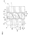
FIG. 1 is a development view illustrating a tread portion of a heavy duty tire in accordance with an embodiment of the present invention; -
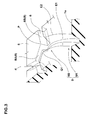
FIG. 2 is a partial enlarged view of a lug groove ofFIG. 1 ; -
FIG. 3 is a perspective view of the lug groove; -
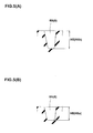
FIG. 4A is a cross-sectional view of the lug groove at an axially outer zigzag corner of a zigzag groove; -
FIG. 4B is a cross-sectional view of the lug groove at a tread edge; -
FIGs. 5A and 5B are cross-sectional views of the zigzag grooves; and -
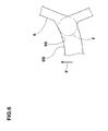
FIG. 6 is a plan view of a groove junction holding a stone. - An embodiment of the present invention will be explained below with reference to the accompanying drawings.
- As shown in
FIG. 1 , aheavy duty tire 1 in accordance with the present embodiment includes atread portion 2 being provided with a circumferentially and continuously extendingmain grooves lateral grooves 4 extending between themain grooves center blocks 5 therebetween. Thus, thetread portion 2 includes ablock row 5R on its central region. - The
main grooves 3 include at least onezigzag groove 6 that includes a plurality of axially outer zigzag corners 7o, a plurality of axiallyinner zigzag corners 7i, and a plurality ofinclined elements 8 each connecting between the axially outer corner 7o and the axiallyinner corner 7i. Thus, eachcenter block 5 has a five or more sided polygon shape on its top surface with at least one corner P being formed of the axially outer corner 7o of thezigzag groove 6. - In this embodiment, both
main grooves zigzag grooves 6, and eachlateral groove 4 straightly extends so as to connect the axiallyinner zigzag corner 7i of onezigzag groove 6 and the axiallyinner zigzag corner 7i of theother zigzag grooves 6. Thus, thecenter block 5 has a six-sided polygon shape (a hexagonal shape) on its top surface in this embodiment. Alternatively, the top surface of thecenter block 5 may have a seven of more sided polygon shape when thelateral groove 4 is a bent groove. Furthermore, the top surface of thecenter block 5 may have a five-sided polygon shape when the one of themain groove 3 extends in a straight manner in the circumferential direction of the tire. Furthermore, thecenter block 5 may be provided with agroove 20 for suitably adjusting its rigidity. Preferably, thegroove 20 has its groove depth of about 50% or less in relation to a groove depth of themain groove 3 orlateral groove 4. - The
tread portion 2 is further provided with a plurality oflug grooves 9 each extending between the tread edge Te and thezigzag groove 6. Thus, the shoulder region between the tread edge Te and thezigzag groove 6 is formed as ashoulder block row 10R that includes a plurality ofshoulder blocks 10 arranged in the circumferential direction of the tire. - Each
lug groove 9 includes an axiallyouter portion 9A extending axially inward from the tread edge Te in a straight manner, and an axiallyinner portion 9B connecting between theouter portion 9A and thezigzag groove 6 while curving in an arc manner toward a first circumferential direction F of the tire. Preferably, thelug groove 9 has an angle α at the tread edge Te in a range of from 65 to 100 degrees, more preferably in a range of from 85 to 95 degrees, with respect to a circumferential line that extends from thelug groove 9 toward the first circumferential direction F. - As shown in
FIG. 2 andFIG. 3 , thelug groove 9 has a first groove edge E1 disposed on a side of the first circumferential direction F with respect to its groove centerline, and a second groove edge E2 facing against the first groove edge E1. The first groove edge E1 of thelug groove 9 is connected to an axially outer groove edge 6e1 of thezigzag groove 6 at an intersection point Q1. The second groove edge E2 of thelug groove 9 is connected to an axially inner groove edge 6e2 of thezigzag groove 6 at an intersection point Q2 through the corner P of thecenter block 5. Namely, a part of thelug groove 9 extends so as to overlap on thezigzag groove 6. Here, thelug groove 9 has its groove depth H9 (shown inFIGs. 4A and 4B ) greater than a groove depth H6 - (shown in
FIGs. 5A and 5B ) of thezigzag groove 6. Thus, thelug groove 9 may be distinguished from thezigzag groove 6 clearly, even in an overlapped portion J between thelug groove 9 and thezigzag groove 6. - The axially
inner portion 9B of thelug groove 9 extends in a single arc manner, or a multiple arc manner that includes a plurality of arcs having different radii of curvature. When the axiallyinner portion 9B of thelug groove 9 extends in the multiple arc manner, the arcs are arranged so that these radii of curvatures are decreasing toward thezigzag groove 6. - The
lug groove 9 comprises a constant groove width WU at thetop surface 2S of thetread portion 2 except for the overlapped portion J. On the other hand, a groove-bottom width WL of thelug groove 9 smoothly decreases axially inward from the tread edge Te. - Preferably, the
lug groove 9 has a ratio WLa/WLb in a range of from 1.4 to 3.0, more preferably in a range of from 1.5 to 2.0, where "WLa" is the groove-bottom width of thelug groove 9 at the tread edge Te (shown inFIGs. 1 and4B ), and "WLb" is the groove-bottom width of thelug groove 9 at the corner P (shown inFIGs. 2 and4A ). Here, the groove-bottom width WLb of thelug groove 9 at the corner P is measured on a plane X extending from the corner P perpendicular to a groove bottom centerline (i) of thelug groove 9. InFIG. 2 , the reference characters "Pi" shows an intersection of the plane X and the groove bottom centerline (i) of thelug groove 9. - As shown in
FIGs 4A and 4B , thelug groove 9 further comprises a pair ofgroove walls top surface 2S of the tread portion are substantially same. Preferably, angles βa of thegroove walls 9S at the tread edge Te are set in a range of from 8 to 25 degrees with respect to the normal perpendicular to atop surface 2S of the tread portion. Preferably, angles βb of thegroove walls 9S at the corner P are set in a range of from 15 to 30 degrees with respect to the normal perpendicular to thetop surface 2S of the tread portion. More preferably, the angles βb are set greater than the angles βa. Here, angles βb of thegroove walls 9S at the corner P are measured on the plane X. - Firstly, since the
tire 1 in accordance with the present invention comprises a plurality of center blocks 5 on its central region of thetread portion 2 where large ground contact pressure tends to be acted, large traction may be generated while maintaining wet grip performance. - Secondly, since the cross-sectional area of each
lug groove 9 increases toward the tread edge Te along with its groove-bottom width WL, it may effectively remove the water from under thetread portion 2 so that wet grip performance may further be improved. Thirdly, since eachlug groove 9 has a constant groove width WU at thetop surface 2S of thetread portion 2, the difference in rigidity within eachshoulder block 10 is reduced so that theshoulder block 10 may exhibit high wear resistance. When the groove-bottom width ratio WLa/WLb is less than 1.4, it might be difficult to drain much water out from the tread edge Te through thelug grooves 9. On the other hand, when the groove-bottom width ratio WLa/WLb is more than 3.0, it might be difficult to improve wet grip performance due to excessively small groove-bottom width WL, or be difficult to improve wear resistance due to excessively large groove-bottom width WL. - Furthermore, the
lug groove 9 includes the axiallyinner portion 9B connected to thezigzag groove 6 while curving in an arc manner. As shown inFIG. 6 , when a stone T is bitten into a groove junction of thezigzag groove 6 and the axiallyinner portion 9B of thelug groove 9, thegroove wall 9S of the axiallyinner portion 9B disposed on the side of the first circumferential direction F may contact with the stone T in line contact or surface contact so as to reduce its contact pressure for holding the stone T. Furthermore, since the axiallyinner portion 9B of thelug groove 9 is formed as an arc manner, the stone T held in the axiallyinner portion 9B tends to move easily during traveling. Thus, thetire 1 in accordance with the present embodiment offers a groove configuration that may easily push the stone away from thelug groove 9, thereby improving stone-biting resistance. Furthermore, the axiallyinner portion 9B of thelug groove 9 may smoothly drain the water toward the tread edge Te, thereby further improving wet grip performance of the tire. - When the angle α of the
lug groove 9 at the tread edge Te is less than 65 degrees, an excessive acute angled corner portion with low rigidity may be formed on theshoulder block 10 between the tread edge Te and thelug groove 9, where uneven wear tends to be generated. On the other hand, when the angle α of thelug groove 9 at the tread edge Te is more than 100 degrees, it might be difficult to smoothly drain the water. - When the groove wall angle βa of the
lug groove 9 at the tread edge Te is less than 8 degrees, thelug groove 9 might be difficult to push the bitten stone out from there. Furthermore, since the difference between the angle βa and the angle βb is excessively small, poor wet grip performance may be offered. On the other hand, when the groove wall angle βa of thelug groove 9 at the tread edge Te is more than 25 degrees, thetread portion 2 may have a relatively small land ratio with low wear resistance. When the groove wall angle βb of thelug groove 9 at the corner P is less than 15 degrees, thelug groove 9 might be difficult to push the bitten stone out from there. When the groove wall angle βb of thelug groove 9 at the corner P is more than 30 degrees, thetread portion 2 may have a relatively small land ratio with low wear resistance. Furthermore, since the difference between the angle βa and the angle βb is excessively small, poor wet grip performance may be offered. - As shown in
FIGs. 5A and 5B , theinclined elements 8 include a firstinclined element 8A extending toward the first circumferential direction F from the axially outer zigzag corner 7o, and a secondinclined element 8B extending toward the opposite direction with respect to the first circumferential direction F from the axially outer zigzag corner 7o. In this embodiment, the firstinclined element 8A has a groove depth H6a, and the secondinclined element 8B has a groove depth H6b larger than the groove depth H6a of the firstinclined element 8A. Thus, stone-biting resistance at the junction of thezigzag groove 6 and thelateral groove 4 may further be improved. - Furthermore, the groove depth H6b of the second
inclined element 8B is preferably set same as a groove depth H4 (not shown) of thelateral groove 4. Thus, as shown inFIG. 1 , a pair of secondinclined elements 8B and onelateral groove 4 arranged therebetween may form an N-shapedgroove configuration 12 with a constant groove depth. Such an N-shapedgroove configuration 12 may offer better drainage performance by communicating a pair oflug grooves 9 arranged both sides of the tire equator C. - While the particularly preferable embodiments of the present invention have been described in detail, the present invention in not limited to the illustrated embodiments, but can be modified and carried out in various aspects.
- To confirm the advantage of the present invention, the heavy duty tires (325/95R24) shown in
FIG. 1 and Table 1 were manufactured and tested with respect to wet grip, stone-biting resistance, wear resistance, and uneven wear resistance. The reference tires (Ref 1 to 3) having straightly extending lug grooves without curved axially inner portion were also manufactured in comparison. - The difference between tires of Ref. 1 and Ex. is only that the lug groove of Ref.1 is not provided with the curved second portion. The tires of Ref.2 and Ref.3 also differ from the tire of Ex.1 in that they have groove widths of the lug grooves at the top surface of the tread portion decreasing axially inward from the tread edge, same as its groove-bottom width. The details of test tires and test methods are as follows.
- Details of test tires:
- Zigzag groove depth H6a: 13.5 mm
- Zigzag groove depth H6b: 18.0 mm
- Lateral groove depth H4: 18.0 mm
- The test tires worn to 75% were installed in a 2-D truck with a half load to its
carrying capacity 10 tons, as its whole wheels using the rim of 24x8.50 and the internal pressure of 850 kPa. Then, a test driver suddenly started the truck using the second gear position by engaging its clutch at the timing of a 1,500 rpm engine speed on a wet asphalt road with a puddle 5mm deep, and measured the time for traveling to 10 m distance. The test results were evaluated as the reciprocal of the time and were indicated using an index based on Ex.1 being 100 in Table 1. The larger the index, the better the wet performance is. - The test tire of Ex. 1 was installed in the truck above as its one of the rear wheels, and the other one of the rear wheels was installed the test tire using the same rim and internal pressure above. Then, the test driver drove the truck until when any one of rear tire worn to 50%. The test results were evaluated as the reciprocal of the number of stones held in the tread grooves of the tire, and were indicated using an index based on Ex.1 being 100 in Table 1. The larger the index, the better the stone-biting resistance is.
- After the stone-biting test, the amount of groove depth left of each test tire was measured. The test results were evaluated as the reciprocal of the number of the amount of groove depth left, and were indicated using an index based on Ex. 1 being 100 in Table 1. The larger the index, the better the wear resistance is.
- After the stone-biting test, the amount of heel and toe wear on the shoulder blocks was measured.
Table 1-1 Ref. 1 Ref. 2 Ref. 3 Ex. 1 Ex. 2 Ex. 3 Ex. 4 Ex. 5 Ex. 6 Ex. 7 Ex. 8 Ex. 9 Lug groove specification Curved axially inner portion Absence Absence Absence Presence Presence Presence Presence Presence Presence Presence Presence Presence Groove angle α (deg. ) 90 90 90 90 65 100 50 120 90 90 90 90 Groove width WU (mm) 26 Non-constant Non-Constant 26 26 26 26 26 Constant Constant Constant Constant Groove depth H9 (mm) 21.6 21.6 21.6 21.6 21.6 21.6 21.6 21.6 21.6 21.6 21.6 21.6 Ratio WLa/WLb 1.6 1 1 1.6 1.6 1.6 1.6 1.6 1.4 3 1 5 Groove wall angle βb (deg.) 22 19.5 22 22 22 22 22 22 22 22 22 22 Groove wall angle βa (deg.) 17 19.5 17 17 17 17 17 17 17 17 17 17 Wet grip performance (Index) 85 65 65 100 100 95 100 83 85 110 80 120 Stone-biting resistance (Index) 65 65 85 100 100 100 95 95 100 100 100 100 Wear resistance (Index) 100 100 95 100 100 100 90 90 100 85 100 80 Amount of heel and Toe wear (mn) 0.3 0.5 1 0.3 1.8 1.8 2.5 2.8 0.5 0.5 0.5 0.5 Table 1-2 Ex. 10 Ex. 11 Ex. 12 Ex. 13 Ex. 14 Ex. 15 Ex. 16 Ex. 17 Lug groove specification Curved axially inner portion Presence Presence Presence Presence Presence Presence Presence Presence Groove angle α (deg.) 90 90 90 90 90 90 90 90 Groove width WU (mm) Constant Constant Constant Constant Constant Constant Constant Constant Groove depth H9 (mm) 21.6 21.6 21.6 21.6 21.6 21.6 21.6 21.6 Ratio WLa/WLb 1.6 1.6 1.6 1.6 1.6 1.6 1.6 1.6 Groove wall angle βb (deg.) 15 30 13 40 22 30 22 30 Groove wall angle βa (deg.) 10 17 8 17 8 25 5 28 Wet grip performance (Index) 95 110 83 120 98 85 95 80 Stone-biting resistance (Index) 85 110 78 120 85 110 80 120 Wear resistance (Index) 100 85 100 78 100 95 100 80 Amount of heel and Toe wear (mm) 1.5 1 1.6 1 1.6 1.6 1.8 1.5
Claims (7)
- A heavy duty tire comprising
a tread portion provided with a pair of circumferentially and continuously extending main grooves disposed on both sides of a tire equator, a plurality of lateral grooves extending between the main grooves to form a plurality of center blocks therebetween, and a plurality of lug grooves,
the main grooves comprising at least one zigzag groove that comprises a plurality of axially outer zigzag corners, a plurality of axially inner zigzag corners, and a plurality of inclined elements each connecting between the axially outer corner and the axially inner corner,
the center block having a five or more sided polygon shape on its top surface with at least one corner being formed of the axially outer zigzag corner of the zigzag groove,
each lug groove extending between a tread edge and the zigzag groove, the lug groove comprising an axially outer portion extending axially inward from the tread edge, and an axially inner portion connecting between the axially outer portion and the zigzag groove while curving toward a first circumferential direction of the tire, the lug groove having a first groove edge disposed on a side of the first circumferential direction with respect to its groove centerline and a second groove edge facing against the first groove edge,
the first groove edge of the lug groove connected to an axially outer groove edge of the zigzag groove, the second groove edge of the lug groove connected to an axially inner groove edge of the zigzag groove through the corner of the center block, and
the lug groove comprising a constant groove width at a top surface of the tread portion, and a groove-bottom width smoothly decreasing axially inward from the tread edge. - The heavy duty tire according to claim 1,
wherein the lug groove has an angle α at the tread edge in a range of from 65 to 100 degrees with respect to a circumferential line that extends from the lug groove toward the first circumferential direction. - The heavy duty tire according to claim 1 or 2,
wherein the lug groove has a ratio WLa/WLb of a groove-bottom width WLa at the tread edge to a groove-bottom width WLb at the axially outer zigzag corner, and
the ratio WLa/WLb is set in a range of from 1.4 to 3.0. - The heavy duty tire according to any one of the claims 1-3,
wherein the lug groove has a pair of groove walls,
each groove wall has an angle βa at the tread edge in a range of from 8 to 25 degrees with respect to a line perpendicular to a top surface of the tread portion,
each groove wall has an angle βb at the axially outer zigzag corner in a range of from 15 to 30 degrees with respect to the line, and
the angle βb is greater than the angle βa. - The heavy duty tire according to any one of the claims 1-4,
wherein the lug groove has a groove depth larger than that of the zigzag groove. - The heavy duty tire according to any one of the claims 1-5, wherein both main grooves are formed as the zigzag grooves, and the lug grooves are disposed on both sides of the tire equator.
- The heavy duty tire according to any one of the claims 1-6, wherein the center block has a six-sided polygon shape.
Applications Claiming Priority (1)
| Application Number | Priority Date | Filing Date | Title |
|---|---|---|---|
| JP2013097046A JP5913190B2 (en) | 2013-05-02 | 2013-05-02 | Heavy duty tire |
Publications (2)
| Publication Number | Publication Date |
|---|---|
| EP2799257A1 true EP2799257A1 (en) | 2014-11-05 |
| EP2799257B1 EP2799257B1 (en) | 2018-09-05 |
Family
ID=50150622
Family Applications (1)
| Application Number | Title | Priority Date | Filing Date |
|---|---|---|---|
| EP14155935.1A Active EP2799257B1 (en) | 2013-05-02 | 2014-02-20 | Heavy duty tire |
Country Status (4)
| Country | Link |
|---|---|
| US (1) | US9701162B2 (en) |
| EP (1) | EP2799257B1 (en) |
| JP (1) | JP5913190B2 (en) |
| CN (1) | CN104129233B (en) |
Cited By (1)
| Publication number | Priority date | Publication date | Assignee | Title |
|---|---|---|---|---|
| CN111016545A (en) * | 2019-12-31 | 2020-04-17 | 安徽佳通乘用子午线轮胎有限公司 | Radial tire capable of resisting lateral sliding abrasion of tire |
Families Citing this family (14)
| Publication number | Priority date | Publication date | Assignee | Title |
|---|---|---|---|---|
| JP1547935S (en) * | 2015-05-18 | 2016-04-18 | ||
| AU2017244887B2 (en) * | 2016-03-31 | 2019-02-28 | The Yokohama Rubber Co., Ltd. | Heavy-duty pneumatic tire |
| JP6900381B2 (en) * | 2016-08-26 | 2021-07-07 | 株式会社ブリヂストン | tire |
| USD821292S1 (en) | 2016-12-20 | 2018-06-26 | Compagnia Generale Des Etablissements Michelin | Tire tread |
| CA175975S (en) | 2017-01-24 | 2018-09-11 | Michelin & Cie | Tire |
| USD882495S1 (en) | 2017-03-01 | 2020-04-28 | Compagnie Generale Des Etablissements Michelin | Tire tread |
| CA179024S (en) | 2017-07-26 | 2018-10-01 | Michelin & Cie | Pneumatic tyre |
| CA181459S (en) | 2017-11-24 | 2019-04-01 | Michelin & Cie | Pneumatic tyre |
| AU201813268S (en) | 2017-12-19 | 2018-06-26 | Michelin & Cie | Tyre |
| JP7172656B2 (en) * | 2019-01-25 | 2022-11-16 | 住友ゴム工業株式会社 | tire |
| CA199606S (en) | 2020-06-03 | 2022-06-10 | Michelin & Cie | Tire |
| USD994589S1 (en) | 2020-12-14 | 2023-08-08 | Compagnie Generale Des Etablissements Michelin | Tire |
| USD993901S1 (en) | 2021-03-04 | 2023-08-01 | Compagnie Generale Des Etablissements Michelin | Tire |
| CA209128S (en) | 2021-07-09 | 2023-09-01 | Michelin & Cie | Tire |
Citations (3)
| Publication number | Priority date | Publication date | Assignee | Title |
|---|---|---|---|---|
| JPH0840020A (en) * | 1994-07-27 | 1996-02-13 | Bridgestone Corp | Pneumatic tire for heavy load |
| JP2001315507A (en) * | 2000-05-01 | 2001-11-13 | Ohtsu Tire & Rubber Co Ltd :The | Pneumatic tire |
| US20080078488A1 (en) * | 2004-11-26 | 2008-04-03 | Bridgestone Corporation | Tire For Heavy Duty Vehicle |
Family Cites Families (6)
| Publication number | Priority date | Publication date | Assignee | Title |
|---|---|---|---|---|
| JP3321262B2 (en) * | 1993-09-10 | 2002-09-03 | 株式会社ブリヂストン | Heavy-duty pneumatic tires for construction vehicles |
| JP3391538B2 (en) * | 1994-02-02 | 2003-03-31 | 住友ゴム工業株式会社 | studless tire |
| FR2800326A1 (en) * | 1999-10-29 | 2001-05-04 | Michelin Soc Tech | TREAD SCULPTURE FOR HIGH LOAD CAPACITY VEHICLE TIRES |
| JP4149219B2 (en) * | 2002-09-11 | 2008-09-10 | 株式会社ブリヂストン | Heavy duty tire |
| JP4996661B2 (en) * | 2009-10-15 | 2012-08-08 | 住友ゴム工業株式会社 | Pneumatic tire |
| JP5452338B2 (en) * | 2010-04-21 | 2014-03-26 | 住友ゴム工業株式会社 | Pneumatic tire |
-
2013
- 2013-05-02 JP JP2013097046A patent/JP5913190B2/en active Active
-
2014
- 2014-02-20 EP EP14155935.1A patent/EP2799257B1/en active Active
- 2014-03-06 US US14/199,388 patent/US9701162B2/en active Active
- 2014-03-10 CN CN201410085563.5A patent/CN104129233B/en active Active
Patent Citations (3)
| Publication number | Priority date | Publication date | Assignee | Title |
|---|---|---|---|---|
| JPH0840020A (en) * | 1994-07-27 | 1996-02-13 | Bridgestone Corp | Pneumatic tire for heavy load |
| JP2001315507A (en) * | 2000-05-01 | 2001-11-13 | Ohtsu Tire & Rubber Co Ltd :The | Pneumatic tire |
| US20080078488A1 (en) * | 2004-11-26 | 2008-04-03 | Bridgestone Corporation | Tire For Heavy Duty Vehicle |
Cited By (2)
| Publication number | Priority date | Publication date | Assignee | Title |
|---|---|---|---|---|
| CN111016545A (en) * | 2019-12-31 | 2020-04-17 | 安徽佳通乘用子午线轮胎有限公司 | Radial tire capable of resisting lateral sliding abrasion of tire |
| CN111016545B (en) * | 2019-12-31 | 2022-07-26 | 安徽佳通乘用子午线轮胎有限公司 | Radial tire capable of resisting lateral sliding abrasion of tire |
Also Published As
| Publication number | Publication date |
|---|---|
| CN104129233B (en) | 2017-06-13 |
| EP2799257B1 (en) | 2018-09-05 |
| JP5913190B2 (en) | 2016-04-27 |
| JP2014218109A (en) | 2014-11-20 |
| CN104129233A (en) | 2014-11-05 |
| US20140326379A1 (en) | 2014-11-06 |
| US9701162B2 (en) | 2017-07-11 |
Similar Documents
| Publication | Publication Date | Title |
|---|---|---|
| EP2799257B1 (en) | Heavy duty tire | |
| US10343461B2 (en) | Heavy duty pneumatic tire | |
| EP2639084B1 (en) | Pneumatic tire | |
| US10730351B2 (en) | Pneumatic tire | |
| US10328751B2 (en) | Pneumatic tire | |
| EP2767413B1 (en) | Heavy duty pneumatic tire | |
| EP3153333B1 (en) | Pneumatic tire | |
| EP3047984A1 (en) | Pneumatic tire | |
| US11685194B2 (en) | Tire | |
| EP2777950B1 (en) | Pneumatic tire | |
| JP2009101846A (en) | Pneumatic tire | |
| JP6490542B2 (en) | Heavy duty tire | |
| EP3115229B1 (en) | Heavy duty pneumatic tire | |
| EP3025878B1 (en) | Heavy duty pneumatic tire | |
| JP2000225815A (en) | Pneumatic tire | |
| US10000092B2 (en) | Pneumatic tire | |
| US9840116B2 (en) | Pneumatic tire | |
| JP2019026010A (en) | tire | |
| JP2006027305A (en) | Pneumatic tire | |
| EP3330101B1 (en) | Pneumatic tire | |
| JP7346960B2 (en) | tire |
Legal Events
| Date | Code | Title | Description |
|---|---|---|---|
| PUAI | Public reference made under article 153(3) epc to a published international application that has entered the european phase |
Free format text: ORIGINAL CODE: 0009012 |
|
| 17P | Request for examination filed |
Effective date: 20140220 |
|
| AK | Designated contracting states |
Kind code of ref document: A1 Designated state(s): AL AT BE BG CH CY CZ DE DK EE ES FI FR GB GR HR HU IE IS IT LI LT LU LV MC MK MT NL NO PL PT RO RS SE SI SK SM TR |
|
| AX | Request for extension of the european patent |
Extension state: BA ME |
|
| R17P | Request for examination filed (corrected) |
Effective date: 20141210 |
|
| RBV | Designated contracting states (corrected) |
Designated state(s): AL AT BE BG CH CY CZ DE DK EE ES FI FR GB GR HR HU IE IS IT LI LT LU LV MC MK MT NL NO PL PT RO RS SE SI SK SM TR |
|
| RIC1 | Information provided on ipc code assigned before grant |
Ipc: B60C 11/11 20060101AFI20180508BHEP Ipc: B60C 11/13 20060101ALI20180508BHEP |
|
| GRAP | Despatch of communication of intention to grant a patent |
Free format text: ORIGINAL CODE: EPIDOSNIGR1 |
|
| STAA | Information on the status of an ep patent application or granted ep patent |
Free format text: STATUS: GRANT OF PATENT IS INTENDED |
|
| INTG | Intention to grant announced |
Effective date: 20180621 |
|
| GRAS | Grant fee paid |
Free format text: ORIGINAL CODE: EPIDOSNIGR3 |
|
| GRAA | (expected) grant |
Free format text: ORIGINAL CODE: 0009210 |
|
| STAA | Information on the status of an ep patent application or granted ep patent |
Free format text: STATUS: THE PATENT HAS BEEN GRANTED |
|
| AK | Designated contracting states |
Kind code of ref document: B1 Designated state(s): AL AT BE BG CH CY CZ DE DK EE ES FI FR GB GR HR HU IE IS IT LI LT LU LV MC MK MT NL NO PL PT RO RS SE SI SK SM TR |
|
| REG | Reference to a national code |
Ref country code: GB Ref legal event code: FG4D |
|
| REG | Reference to a national code |
Ref country code: CH Ref legal event code: EP |
|
| REG | Reference to a national code |
Ref country code: AT Ref legal event code: REF Ref document number: 1037364 Country of ref document: AT Kind code of ref document: T Effective date: 20180915 |
|
| REG | Reference to a national code |
Ref country code: IE Ref legal event code: FG4D |
|
| REG | Reference to a national code |
Ref country code: DE Ref legal event code: R096 Ref document number: 602014031601 Country of ref document: DE |
|
| REG | Reference to a national code |
Ref country code: NL Ref legal event code: MP Effective date: 20180905 |
|
| REG | Reference to a national code |
Ref country code: LT Ref legal event code: MG4D |
|
| PG25 | Lapsed in a contracting state [announced via postgrant information from national office to epo] |
Ref country code: FI Free format text: LAPSE BECAUSE OF FAILURE TO SUBMIT A TRANSLATION OF THE DESCRIPTION OR TO PAY THE FEE WITHIN THE PRESCRIBED TIME-LIMIT Effective date: 20180905 Ref country code: NO Free format text: LAPSE BECAUSE OF FAILURE TO SUBMIT A TRANSLATION OF THE DESCRIPTION OR TO PAY THE FEE WITHIN THE PRESCRIBED TIME-LIMIT Effective date: 20181205 Ref country code: RS Free format text: LAPSE BECAUSE OF FAILURE TO SUBMIT A TRANSLATION OF THE DESCRIPTION OR TO PAY THE FEE WITHIN THE PRESCRIBED TIME-LIMIT Effective date: 20180905 Ref country code: GR Free format text: LAPSE BECAUSE OF FAILURE TO SUBMIT A TRANSLATION OF THE DESCRIPTION OR TO PAY THE FEE WITHIN THE PRESCRIBED TIME-LIMIT Effective date: 20181206 Ref country code: BG Free format text: LAPSE BECAUSE OF FAILURE TO SUBMIT A TRANSLATION OF THE DESCRIPTION OR TO PAY THE FEE WITHIN THE PRESCRIBED TIME-LIMIT Effective date: 20181205 Ref country code: SE Free format text: LAPSE BECAUSE OF FAILURE TO SUBMIT A TRANSLATION OF THE DESCRIPTION OR TO PAY THE FEE WITHIN THE PRESCRIBED TIME-LIMIT Effective date: 20180905 Ref country code: LT Free format text: LAPSE BECAUSE OF FAILURE TO SUBMIT A TRANSLATION OF THE DESCRIPTION OR TO PAY THE FEE WITHIN THE PRESCRIBED TIME-LIMIT Effective date: 20180905 |
|
| REG | Reference to a national code |
Ref country code: AT Ref legal event code: MK05 Ref document number: 1037364 Country of ref document: AT Kind code of ref document: T Effective date: 20180905 |
|
| PG25 | Lapsed in a contracting state [announced via postgrant information from national office to epo] |
Ref country code: HR Free format text: LAPSE BECAUSE OF FAILURE TO SUBMIT A TRANSLATION OF THE DESCRIPTION OR TO PAY THE FEE WITHIN THE PRESCRIBED TIME-LIMIT Effective date: 20180905 Ref country code: LV Free format text: LAPSE BECAUSE OF FAILURE TO SUBMIT A TRANSLATION OF THE DESCRIPTION OR TO PAY THE FEE WITHIN THE PRESCRIBED TIME-LIMIT Effective date: 20180905 Ref country code: AL Free format text: LAPSE BECAUSE OF FAILURE TO SUBMIT A TRANSLATION OF THE DESCRIPTION OR TO PAY THE FEE WITHIN THE PRESCRIBED TIME-LIMIT Effective date: 20180905 |
|
| PG25 | Lapsed in a contracting state [announced via postgrant information from national office to epo] |
Ref country code: CZ Free format text: LAPSE BECAUSE OF FAILURE TO SUBMIT A TRANSLATION OF THE DESCRIPTION OR TO PAY THE FEE WITHIN THE PRESCRIBED TIME-LIMIT Effective date: 20180905 Ref country code: RO Free format text: LAPSE BECAUSE OF FAILURE TO SUBMIT A TRANSLATION OF THE DESCRIPTION OR TO PAY THE FEE WITHIN THE PRESCRIBED TIME-LIMIT Effective date: 20180905 Ref country code: IS Free format text: LAPSE BECAUSE OF FAILURE TO SUBMIT A TRANSLATION OF THE DESCRIPTION OR TO PAY THE FEE WITHIN THE PRESCRIBED TIME-LIMIT Effective date: 20190105 Ref country code: ES Free format text: LAPSE BECAUSE OF FAILURE TO SUBMIT A TRANSLATION OF THE DESCRIPTION OR TO PAY THE FEE WITHIN THE PRESCRIBED TIME-LIMIT Effective date: 20180905 Ref country code: PL Free format text: LAPSE BECAUSE OF FAILURE TO SUBMIT A TRANSLATION OF THE DESCRIPTION OR TO PAY THE FEE WITHIN THE PRESCRIBED TIME-LIMIT Effective date: 20180905 Ref country code: EE Free format text: LAPSE BECAUSE OF FAILURE TO SUBMIT A TRANSLATION OF THE DESCRIPTION OR TO PAY THE FEE WITHIN THE PRESCRIBED TIME-LIMIT Effective date: 20180905 Ref country code: NL Free format text: LAPSE BECAUSE OF FAILURE TO SUBMIT A TRANSLATION OF THE DESCRIPTION OR TO PAY THE FEE WITHIN THE PRESCRIBED TIME-LIMIT Effective date: 20180905 Ref country code: AT Free format text: LAPSE BECAUSE OF FAILURE TO SUBMIT A TRANSLATION OF THE DESCRIPTION OR TO PAY THE FEE WITHIN THE PRESCRIBED TIME-LIMIT Effective date: 20180905 Ref country code: IT Free format text: LAPSE BECAUSE OF FAILURE TO SUBMIT A TRANSLATION OF THE DESCRIPTION OR TO PAY THE FEE WITHIN THE PRESCRIBED TIME-LIMIT Effective date: 20180905 |
|
| PG25 | Lapsed in a contracting state [announced via postgrant information from national office to epo] |
Ref country code: SM Free format text: LAPSE BECAUSE OF FAILURE TO SUBMIT A TRANSLATION OF THE DESCRIPTION OR TO PAY THE FEE WITHIN THE PRESCRIBED TIME-LIMIT Effective date: 20180905 Ref country code: SK Free format text: LAPSE BECAUSE OF FAILURE TO SUBMIT A TRANSLATION OF THE DESCRIPTION OR TO PAY THE FEE WITHIN THE PRESCRIBED TIME-LIMIT Effective date: 20180905 Ref country code: PT Free format text: LAPSE BECAUSE OF FAILURE TO SUBMIT A TRANSLATION OF THE DESCRIPTION OR TO PAY THE FEE WITHIN THE PRESCRIBED TIME-LIMIT Effective date: 20190105 |
|
| REG | Reference to a national code |
Ref country code: DE Ref legal event code: R097 Ref document number: 602014031601 Country of ref document: DE |
|
| PLBE | No opposition filed within time limit |
Free format text: ORIGINAL CODE: 0009261 |
|
| STAA | Information on the status of an ep patent application or granted ep patent |
Free format text: STATUS: NO OPPOSITION FILED WITHIN TIME LIMIT |
|
| PG25 | Lapsed in a contracting state [announced via postgrant information from national office to epo] |
Ref country code: DK Free format text: LAPSE BECAUSE OF FAILURE TO SUBMIT A TRANSLATION OF THE DESCRIPTION OR TO PAY THE FEE WITHIN THE PRESCRIBED TIME-LIMIT Effective date: 20180905 |
|
| 26N | No opposition filed |
Effective date: 20190606 |
|
| PG25 | Lapsed in a contracting state [announced via postgrant information from national office to epo] |
Ref country code: SI Free format text: LAPSE BECAUSE OF FAILURE TO SUBMIT A TRANSLATION OF THE DESCRIPTION OR TO PAY THE FEE WITHIN THE PRESCRIBED TIME-LIMIT Effective date: 20180905 |
|
| REG | Reference to a national code |
Ref country code: CH Ref legal event code: PL |
|
| GBPC | Gb: european patent ceased through non-payment of renewal fee |
Effective date: 20190220 |
|
| PG25 | Lapsed in a contracting state [announced via postgrant information from national office to epo] |
Ref country code: LU Free format text: LAPSE BECAUSE OF NON-PAYMENT OF DUE FEES Effective date: 20190220 Ref country code: MC Free format text: LAPSE BECAUSE OF FAILURE TO SUBMIT A TRANSLATION OF THE DESCRIPTION OR TO PAY THE FEE WITHIN THE PRESCRIBED TIME-LIMIT Effective date: 20180905 |
|
| REG | Reference to a national code |
Ref country code: BE Ref legal event code: MM Effective date: 20190228 |
|
| REG | Reference to a national code |
Ref country code: IE Ref legal event code: MM4A |
|
| PG25 | Lapsed in a contracting state [announced via postgrant information from national office to epo] |
Ref country code: LI Free format text: LAPSE BECAUSE OF NON-PAYMENT OF DUE FEES Effective date: 20190228 Ref country code: CH Free format text: LAPSE BECAUSE OF NON-PAYMENT OF DUE FEES Effective date: 20190228 |
|
| PG25 | Lapsed in a contracting state [announced via postgrant information from national office to epo] |
Ref country code: IE Free format text: LAPSE BECAUSE OF NON-PAYMENT OF DUE FEES Effective date: 20190220 Ref country code: GB Free format text: LAPSE BECAUSE OF NON-PAYMENT OF DUE FEES Effective date: 20190220 |
|
| PG25 | Lapsed in a contracting state [announced via postgrant information from national office to epo] |
Ref country code: BE Free format text: LAPSE BECAUSE OF NON-PAYMENT OF DUE FEES Effective date: 20190228 |
|
| PG25 | Lapsed in a contracting state [announced via postgrant information from national office to epo] |
Ref country code: TR Free format text: LAPSE BECAUSE OF FAILURE TO SUBMIT A TRANSLATION OF THE DESCRIPTION OR TO PAY THE FEE WITHIN THE PRESCRIBED TIME-LIMIT Effective date: 20180905 |
|
| PG25 | Lapsed in a contracting state [announced via postgrant information from national office to epo] |
Ref country code: MT Free format text: LAPSE BECAUSE OF NON-PAYMENT OF DUE FEES Effective date: 20190220 |
|
| PG25 | Lapsed in a contracting state [announced via postgrant information from national office to epo] |
Ref country code: CY Free format text: LAPSE BECAUSE OF FAILURE TO SUBMIT A TRANSLATION OF THE DESCRIPTION OR TO PAY THE FEE WITHIN THE PRESCRIBED TIME-LIMIT Effective date: 20180905 |
|
| PG25 | Lapsed in a contracting state [announced via postgrant information from national office to epo] |
Ref country code: HU Free format text: LAPSE BECAUSE OF FAILURE TO SUBMIT A TRANSLATION OF THE DESCRIPTION OR TO PAY THE FEE WITHIN THE PRESCRIBED TIME-LIMIT; INVALID AB INITIO Effective date: 20140220 |
|
| PG25 | Lapsed in a contracting state [announced via postgrant information from national office to epo] |
Ref country code: MK Free format text: LAPSE BECAUSE OF FAILURE TO SUBMIT A TRANSLATION OF THE DESCRIPTION OR TO PAY THE FEE WITHIN THE PRESCRIBED TIME-LIMIT Effective date: 20180905 |
|
| PGFP | Annual fee paid to national office [announced via postgrant information from national office to epo] |
Ref country code: FR Payment date: 20230110 Year of fee payment: 10 |
|
| PGFP | Annual fee paid to national office [announced via postgrant information from national office to epo] |
Ref country code: DE Payment date: 20221229 Year of fee payment: 10 |