EP2799248A1 - Tire and tire-forming mold - Google Patents
Tire and tire-forming mold Download PDFInfo
- Publication number
- EP2799248A1 EP2799248A1 EP12861816.2A EP12861816A EP2799248A1 EP 2799248 A1 EP2799248 A1 EP 2799248A1 EP 12861816 A EP12861816 A EP 12861816A EP 2799248 A1 EP2799248 A1 EP 2799248A1
- Authority
- EP
- European Patent Office
- Prior art keywords
- tire
- tread
- mold
- performance
- preferable
- Prior art date
- Legal status (The legal status is an assumption and is not a legal conclusion. Google has not performed a legal analysis and makes no representation as to the accuracy of the status listed.)
- Granted
Links
- 238000000465 moulding Methods 0.000 claims abstract description 75
- 230000003746 surface roughness Effects 0.000 claims description 25
- 239000000463 material Substances 0.000 description 57
- 238000005422 blasting Methods 0.000 description 37
- 239000002245 particle Substances 0.000 description 14
- 238000005516 engineering process Methods 0.000 description 12
- 238000000034 method Methods 0.000 description 12
- 239000011324 bead Substances 0.000 description 7
- 230000015556 catabolic process Effects 0.000 description 7
- 238000006731 degradation reaction Methods 0.000 description 7
- 238000004519 manufacturing process Methods 0.000 description 6
- 230000005484 gravity Effects 0.000 description 5
- 238000004073 vulcanization Methods 0.000 description 4
- 230000000694 effects Effects 0.000 description 3
- 238000011156 evaluation Methods 0.000 description 3
- XLYOFNOQVPJJNP-UHFFFAOYSA-N water Substances O XLYOFNOQVPJJNP-UHFFFAOYSA-N 0.000 description 3
- 238000012935 Averaging Methods 0.000 description 2
- XEEYBQQBJWHFJM-UHFFFAOYSA-N Iron Chemical compound [Fe] XEEYBQQBJWHFJM-UHFFFAOYSA-N 0.000 description 2
- XAGFODPZIPBFFR-UHFFFAOYSA-N aluminium Chemical compound [Al] XAGFODPZIPBFFR-UHFFFAOYSA-N 0.000 description 2
- 229910052782 aluminium Inorganic materials 0.000 description 2
- 239000000919 ceramic Substances 0.000 description 2
- 238000001878 scanning electron micrograph Methods 0.000 description 2
- 229910001208 Crucible steel Inorganic materials 0.000 description 1
- 230000000052 comparative effect Effects 0.000 description 1
- 230000003247 decreasing effect Effects 0.000 description 1
- 230000006866 deterioration Effects 0.000 description 1
- 230000009189 diving Effects 0.000 description 1
- 238000003384 imaging method Methods 0.000 description 1
- 229910052742 iron Inorganic materials 0.000 description 1
- 238000004643 material aging Methods 0.000 description 1
- 238000001000 micrograph Methods 0.000 description 1
- 238000007493 shaping process Methods 0.000 description 1
- 239000000126 substance Substances 0.000 description 1
- 230000001629 suppression Effects 0.000 description 1
Images




Classifications
-
- B—PERFORMING OPERATIONS; TRANSPORTING
- B60—VEHICLES IN GENERAL
- B60C—VEHICLE TYRES; TYRE INFLATION; TYRE CHANGING; CONNECTING VALVES TO INFLATABLE ELASTIC BODIES IN GENERAL; DEVICES OR ARRANGEMENTS RELATED TO TYRES
- B60C11/00—Tyre tread bands; Tread patterns; Anti-skid inserts
-
- B—PERFORMING OPERATIONS; TRANSPORTING
- B29—WORKING OF PLASTICS; WORKING OF SUBSTANCES IN A PLASTIC STATE IN GENERAL
- B29C—SHAPING OR JOINING OF PLASTICS; SHAPING OF MATERIAL IN A PLASTIC STATE, NOT OTHERWISE PROVIDED FOR; AFTER-TREATMENT OF THE SHAPED PRODUCTS, e.g. REPAIRING
- B29C33/00—Moulds or cores; Details thereof or accessories therefor
- B29C33/42—Moulds or cores; Details thereof or accessories therefor characterised by the shape of the moulding surface, e.g. ribs or grooves
- B29C33/424—Moulding surfaces provided with means for marking or patterning
-
- B—PERFORMING OPERATIONS; TRANSPORTING
- B29—WORKING OF PLASTICS; WORKING OF SUBSTANCES IN A PLASTIC STATE IN GENERAL
- B29D—PRODUCING PARTICULAR ARTICLES FROM PLASTICS OR FROM SUBSTANCES IN A PLASTIC STATE
- B29D30/00—Producing pneumatic or solid tyres or parts thereof
- B29D30/06—Pneumatic tyres or parts thereof (e.g. produced by casting, moulding, compression moulding, injection moulding, centrifugal casting)
- B29D30/0601—Vulcanising tyres; Vulcanising presses for tyres
- B29D30/0606—Vulcanising moulds not integral with vulcanising presses
-
- B—PERFORMING OPERATIONS; TRANSPORTING
- B29—WORKING OF PLASTICS; WORKING OF SUBSTANCES IN A PLASTIC STATE IN GENERAL
- B29D—PRODUCING PARTICULAR ARTICLES FROM PLASTICS OR FROM SUBSTANCES IN A PLASTIC STATE
- B29D30/00—Producing pneumatic or solid tyres or parts thereof
- B29D30/06—Pneumatic tyres or parts thereof (e.g. produced by casting, moulding, compression moulding, injection moulding, centrifugal casting)
- B29D30/0601—Vulcanising tyres; Vulcanising presses for tyres
- B29D30/0606—Vulcanising moulds not integral with vulcanising presses
- B29D2030/0607—Constructional features of the moulds
- B29D2030/0616—Surface structure of the mould, e.g. roughness, arrangement of slits, grooves or channels
-
- B—PERFORMING OPERATIONS; TRANSPORTING
- B29—WORKING OF PLASTICS; WORKING OF SUBSTANCES IN A PLASTIC STATE IN GENERAL
- B29D—PRODUCING PARTICULAR ARTICLES FROM PLASTICS OR FROM SUBSTANCES IN A PLASTIC STATE
- B29D30/00—Producing pneumatic or solid tyres or parts thereof
- B29D30/06—Pneumatic tyres or parts thereof (e.g. produced by casting, moulding, compression moulding, injection moulding, centrifugal casting)
- B29D30/52—Unvulcanised treads, e.g. on used tyres; Retreading
- B29D30/66—Moulding treads on to tyre casings, e.g. non-skid treads with spikes
- B29D2030/667—Treads with antiskid properties, e.g. having special patterns or special rubber compositions
-
- B—PERFORMING OPERATIONS; TRANSPORTING
- B29—WORKING OF PLASTICS; WORKING OF SUBSTANCES IN A PLASTIC STATE IN GENERAL
- B29K—INDEXING SCHEME ASSOCIATED WITH SUBCLASSES B29B, B29C OR B29D, RELATING TO MOULDING MATERIALS OR TO MATERIALS FOR MOULDS, REINFORCEMENTS, FILLERS OR PREFORMED PARTS, e.g. INSERTS
- B29K2995/00—Properties of moulding materials, reinforcements, fillers, preformed parts or moulds
- B29K2995/0037—Other properties
- B29K2995/0072—Roughness, e.g. anti-slip
- B29K2995/0074—Roughness, e.g. anti-slip patterned, grained
-
- B—PERFORMING OPERATIONS; TRANSPORTING
- B29—WORKING OF PLASTICS; WORKING OF SUBSTANCES IN A PLASTIC STATE IN GENERAL
- B29L—INDEXING SCHEME ASSOCIATED WITH SUBCLASS B29C, RELATING TO PARTICULAR ARTICLES
- B29L2030/00—Pneumatic or solid tyres or parts thereof
Definitions
- the present invention relates to tires and tire forming molds, and more particularly, to tires that are excellent in on-ice performance and on-snow performance, and tire forming molds used for manufacturing the same.
- JP 2002-192914 A (PTL 1).
- JP H11-301217 A (PTL 2) proposes a technology which uses foamed rubber as a cap rubber on a tire having a tread rubber with a so-called cap-and-base structure comprising a cap rubber and a base rubber, thereby significantly improving the drainage performance and the on-ice performance and on-snow performance of the tire.
- JP 2009-67378 A proposes, as is shown in FIG. 1(a) , for the surface properties of the tread portion 1 of the tire, a technology which increases the roughness of the surface, increases the frictional force between the tire surface and a road surface, and improves the on-ice performance and on-snow performance of the tire, by providing protrusions 2 with a sharp-ended shape on the surface of the tread portion.
- An object of the present invention is to solve the aforementioned problems, and to provide a tire with improved on-ice performance and on-snow performance and a tire forming mold used for manufacturing (forming) the same.
- the inventor has intensively studied to solve the problems aforementioned.
- the present inventor has completed the present invention by finding that by forming a predetermined microstructure on the tread surface of the tread portion, it is possible to suppress the reduction of the block rigidity and the drainage performance of a tire, thereby to obtain further improved on-ice performance and on-snow performance of the tire, and to allow the tire to exhibit sufficient on-ice performance and on-snow performance even when the tire is brand new.
- the tire of the present invention is characterized in that at least a part of the tread surface of the tread portion has a surface roughness at which the maximum profile peak height Rp is 5 ⁇ m or more and 70 ⁇ m or less.
- the maximum profile peak height Rp is 5 ⁇ m or more and 70 ⁇ m or less on at least a part of the tread surface of the tread portion, and consequently it is possible to further suppress the degradation of the block rigidity and the drainage performance, and simultaneously improve the on-ice performance and on-snow performance of the tire sufficiently.
- the maximum profile peak height Rp is 5 ⁇ m or more, therefore the water-removing space may be ensured, while the maximum profile peak height Rp is 70 ⁇ m or less, therefore the frictional force between the tire and the road surface may be ensured.
- maximum profile peak height Rp refers to the “maximum profile peak height Rp" specified by JIS B 0601 (2001). Note that Rp may be determined by measuring the peak height existing in a unit length (1mm).
- the tire forming mold of the present invention is a mold for tire forming, which is characterized by having a tread-surface molding surface for molding a tread surface of the tread portion, and at least a part of the tread-surface molding surface has a surface roughness at which the maximum profile peak height Rp is 5 ⁇ m or more and 70 ⁇ m or less.
- the tire and the tire forming mold of the present invention is explained hereinafter.
- the tire of the present invention is characterized in that a predetermined microstructure is formed on at least a part of the tread surface (the surface that contacts a road surface) of the tread portion, and the tread portion has predetermined surface properties (tread surface properties).
- the tire forming mold of the present invention is used for manufacturing the tire of the present invention, characterized in that the tread-surface molding surface has predetermined surface properties by forming a predetermined microstructure on the inner surface of the mold, specifically at least a part of the tread-surface molding surface for molding the tread surface of the tire.
- FIG. 2 is a sectional view of the tire according to an embodiment of the present invention taken along the tire width direction.
- a tire 20 has a pair of bead portions 4, a pair of sidewall portions 5, each extending outwardly in the tire radial direction from each bead portion 4, and a tread portion 6 extending between the sidewall portions 5.
- the tire 20 of the embodiment has a carcass 7 toroidally extending between a pair of bead cores 4a which are embedded in the pair of bead portions 4, and a belt 8 including belt layers 8a and 8b which are disposed on the outside of the carcass 7 in the tire radial direction. Further, a tread rubber made from non-foamed rubber is disposed on the outside of belt 8 in the tire radial direction.
- micro protrusions with a predetermined shape are formed on at least a part of the tread surface (in this embodiment, the entire tread surface) of the tire 20.
- the tread surface in this embodiment, the entire tread surface
- FIG. 3(a) an enlarged plan view of a surface 6a of the tread portion 6 shown in FIG. 3(a)
- FIG. 3(b) an enlarged view of the tread portion 6 on the surface 6a side along the tire width direction shown in FIG. 3(b)
- the tire according to this embodiment has a large number of micro protrusions 9, each being convex outwardly in the tire radial direction (of hemispherical shape, in the illustrated example) formed on the outside of the entire tread surface 6a of the tread portion, and at least a part of the tread surface 6a of the tread portion has a surface roughness at which the maximum profile peak height is 5 ⁇ m or more and 70 ⁇ m or less.
- FIG. 3 shows a case that the protrusions 9 are hemispherical protrusions
- the protrusions may be of various shapes, such as trapezoidal cross section shapes as shown in FIG. 7(a) , including truncated conical shape and truncated pyramidal shape, rectangular cross section shapes as shown in FIG. 7(b) , including cylindrical shape and prismatic shape, and truncated hemispherical shapes as shown in FIG. 7(c) .
- the tread surface of the tread portion has a surface roughness at which the maximum profile peak height Rp is 5 ⁇ m or more and 70 ⁇ m or less, and consequently it is possible to suppress the degradation of the block rigidity and the drainage performance, and simultaneously improve the on-ice performance and on-snow performance of the tire sufficiently.
- the maximum height of profile peak Rp is 5 ⁇ m or more, and therefore the water-removing space may be ensured, while the maximum height of profile peak Rp is 70 ⁇ m or less, and therefore the frictional force between the tire and the road surface may be ensured.
- the suppression of the degradation of the drainage performance and the improvement of the on-ice performance and on-snow performance is accomplished by forming micro protrusions 9 having a predetermined shape, and therefore there is no need to form an excessive number of sipes, or utilize foamed rubber, etc.
- the tire 20 may exhibit sufficient on-ice performance and on-snow performance even when the tire is new (in unused state), although the reason is not clear.
- the part with protrusions 9 formed thereon has surface properties having a surface roughness at which the maximum profile peak height Rp is 10 ⁇ m or more and 40 ⁇ m or less, for the same reason.
- the protrusions 9 have a hemispherical shape. This is because that if the protrusions 9 have a hemispherical shape, the protrusions 9 are unlikely to collapse and the drainage performance may be ensured.
- the height H of the protrusions 9 formed on the tread surface of the tread portion is 1 to 50 ⁇ m. This is because that if the height H is set to be 1 ⁇ m or more, it is possible to improve the drainage performance by ensuring a sufficient volume of gaps among the protrusions 9. In addition, if the height H of the protrusions 9 is set to be 50 ⁇ m or less, it is possible to sufficiently ensure the drainage performance by increasing the rigidity of the protrusions 9.
- Protrusion height refers to the distance along the tire radial direction between a first imaginary plane perpendicular to a tire radial direction line extending across the distal ends of the protrusions (the outer ends in the tire radial direction), and a second imaginary plane closest to the first imaginary plane among the imaginary planes contacting the outer contour line of the protrusions 9 and perpendicular to the tire radial direction line.
- the "protrusion number" and “protrusion height” of the present invention may be measured, for example, by enlarging the tread surface of the tread with an SEM or a microscope.
- protrusions with a height H of more than 20 ⁇ m are formed in a number density of 80/mm 2 or more on at least a part of the tread surface of the tread. In this way, it is possible to further suppress the degradation of block rigidity and drainage performance, and simultaneously improve the on-ice performance and on-snow performance of tires.
- protrusions having a height of 20 ⁇ m or more are formed, and therefore it is possible to ensure the water-removing space between the protrusions, while protrusions having a height of 20 ⁇ m or more are formed in a number density of 80/mm 2 or more, and therefore it is possible to ensure the ground contact area of the protrusions.
- the part with protrusions 9 with a height of more than 20 ⁇ m formed thereon has a number density of protrusions of 150/mm 2 or more. It is more preferable that the number density of the protrusions with a height of more than 20 ⁇ m is 150/mm 2 or more and 250/mm 2 or less.
- protrusions with a preferable protrusion height of more than 30 ⁇ m are formed in a number density of 100/mm 2 or more. Additionally, it is preferable that the protrusion height is less than 50 ⁇ m. This is because that if the protrusion height is 50 ⁇ m or more, there is a possibility that the protrusion rigidity is degraded, and in the case where a large load is placed on the tire, protrusions may collapse and fail to provide braking force.
- the "protrusion number" and "protrusion height" of the present invention may be measured, for example, by enlarging the tread surface of the tread with an SEM or a microscope.
- the tread surface of the tread portion has a surface roughness at which the roughness motif maximum length A is 5 ⁇ m or more and 100 ⁇ m or less.
- the tread surface of the tread portion has a surface roughness at which the roughness motif maximum length is 5 ⁇ m or more and 100 ⁇ m or less, and consequently it is possible to further suppress the degradation of the block rigidity and the drainage performance, and simultaneously further improve the on-ice performance and on-snow performance of the tire sufficiently.
- the roughness motif maximum length A is 5 ⁇ m or more, therefore the water-removing space may be ensured, while the upper limit of the roughness motif maximum length is 100 ⁇ m, therefore the frictional force between the tire and the road surface may be ensured.
- the part with protrusions 9 formed thereon has surface properties having a surface roughness at which the roughness motif maximum length A is 20 ⁇ m or more and 80 ⁇ m or less, for the same reason.
- the term "roughness motif maximum length A” refers to the “roughness motif maximum length A” specified by JIS B 0631 (2000), and is measured with a microscope, etc., under no-load condition.
- the tire of the present invention has a surface roughness at which the mean height of profile elements Rc is 1 ⁇ m or more and 50 ⁇ m or less, on at least a part of the tread surface of the tread portion.
- the surface roughness of the tread surface of the tread portion to have a mean height of profile elements Rc of 1 ⁇ m or more and 50 ⁇ m or less, it is possible to further suppress the degradation of the block rigidity and the drainage performance, and simultaneously improve the on-ice performance and on-snow performance of the tire sufficiently.
- the surface properties of the tread surface of the tread portion by setting the mean height of profile elements Rc to be 1 ⁇ m or more, the water-removing space may be ensured, while by setting the mean height of profile elements Rc to be 50 ⁇ m or less, the protrusion rigidity may be ensured.
- the part has surface properties having a surface roughness at which the mean height of profile elements Rc is 10 ⁇ m or more and 40 ⁇ m or less, for the same reason.
- the term "mean height of profile elements Rc" refers to the “mean height of profile elements Rc" specified by JIS B 0601 (2001).
- Rc may be determined by measuring the heights of the peaks existing in a unit length (1mm), and averaging the same excluding the heights of those peaks included in the range of 10% higher and lower than a height reference.
- the ten-point average roughness Rz of the tread surface of the tread portion of the tire with protrusions with a hemispherical shape formed thereon is 1.0 to 50 ⁇ m.
- ten-point average roughness Rz refers to a value measured in accordance with the provisions of JIS B0601 (1994), based on the reference length of 0.8mm and the evaluation length of 4mm.
- the mean spacing S of local peaks of the protrusions 9 formed on the tread surface of the tread portion of the tire is set to be 5.0 to 100 ⁇ m.
- spacing S is 5.0 ⁇ m or more, the gaps for water removing may be ensured, while by setting spacing S to be 100 ⁇ m or less, the contacting area with the road surface may be ensured, and thereby it is possible to further improve the on-ice performance and on-snow performance of the tire.
- mean spacing of local peaks refers to a value measured in accordance with the provisions of JIS B0601 (1994), based on the reference length of 0.8mm and the evaluation length of 4mm.
- the aforementioned tire is not particularly limited and may be manufactured with the tire forming mold as follows. Further, the forming of the tire utilizing the tire forming mold as follows may be performed with ordinary methods.
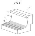
- FIG. 5 is a schematic partial perspective view showing a part of the tire forming mold utilized in forming the tire of the present invention.
- the mold 10 has a molding surface 11 for the vulcanization forming of the tire.
- the molding surface 11 has a tread-surface molding surface 11 a for molding the tread surface of the tread portion, and according to the example as shown, it also has a sidewall-portion molding surface 11b for molding the outside surface of a sidewall portion, and a bead-portion molding surface 11c for molding the outside surface of the bead portion.
- the molding surface 11 is not particularly limited, and may be formed with aluminum, for example.
- the tread surface of the tread portion of the tread portion of the tire of the present invention having the aforementioned surface properties may be formed with a tire vulcanization mold 10 comprising the tread-surface molding surface 11a having the aforementioned surface properties.
- the tire-forming mold 10 according to the present embodiment has a large number of recesses 12 on the entire tread surface molding surface 11a for molding the tread surface of the tread portion of the tire.
- the tread-surface molding surface (in the illustrated example, the entire tread-surface molding surface) has a surface roughness at which the maximum profile peak height Rp is 5 ⁇ m or more and 70 ⁇ m or less.
- FIG. 6 illustrates a case that the recesses 12 are recesses with a hemispherical shape
- the recesses 12 of the mold of the present invention may also be recesses of truncated hemisphere shape, truncated conical shape, truncated pyramidal shape, cylindrical shape or prismatic shape.
- the surface shape of the tread-surface molding surface 11 a of mold 10 is transferred as the surface shape of the tread surface of the tread portion of the tire. Additionally, a large number of protrusions 9 are formed on the tread surface of the tread portion of the manufactured tire, and the tread surface of the tread portion has a surface roughness at which the maximum profile peak height Rp is 5 ⁇ m or more and 70 ⁇ m or less. Therefore, it is possible to form a tire excellent in on-ice performance and on-snow performance.
- the aforementioned tread-surface molding surface 11 a may be formed via a blast material blasting process whereby blast materials of a particular shape are blasted and forced to impact the molding surface.
- the tire forming mold obtained via the blast material blasting process has a large number of the aforementioned recesses 12 on the tread-surface molding surface, and has a surface roughness at which maximum profile peak height Rp is 5 ⁇ m or more and 70 ⁇ m or less, on at least a part of the tread-surface molding surface, and consequently the tread surface of the tread portion of the tire vulcanization formed utilizing the mold has the aforementioned surface roughness at which the maximum profile peak height Rp is 5 ⁇ m or more and 70 ⁇ m or less.
- the aforementioned tread-surface molding surface 11a is formed by blasting spherical blast materials with a sphericity of 15 ⁇ m or less and forcing the same to impact the tread-surface molding surface.
- the sphericity of the blast materials herein is set to be 10 ⁇ m or less.
- the sphericity of the blast materials is set to be 5 ⁇ m or less.
- the average particle size of the blast materials utilized in the blast material blasting process is set to be 10 ⁇ m to 1mm.
- the average particle size of the blast materials is set to be 20 ⁇ m to 0.7mm, still more preferably 30 ⁇ m to 0.5mm.
- the term "average particle size” refers to the value obtained by imaging blasting materials with SEM, then randomly taking out 10 blasting materials therefrom, obtaining the average value of the diameter of the inscribed circle and the diameter of the circumscribed circle of each blast material, and averaging the results of the 10 blast materials.
- the Mohs hardness of the blast materials is set to be 2 to 10.
- the Mohs hardness of the blast materials is set to be 3.0 to 9.0, still more preferably 5.0 to 9.0.
- the Mohs hardness of the tread-surface molding surface of the tire forming mold is set to be 2.0 to 5.0, and that the difference between the Mohs hardness of the tread-surface molding surface of the tire forming mold and the blast materials is set to be 3.0 to 5.0.
- the specific gravity of the blast materials is set to be 0.5 to 20.
- the specific gravity of the blast materials may be 0.5 or more, the operability may be improved by suppressing the splashing around of the blast materials in the blasting process.
- the specific gravity of the blast materials may be 20 or less, it is possible to reduce the energy needed for accelerating the blast materials, and to suppress the rapid wearing of the mold.
- the specific gravity of the blast materials is set to be 0.8 to 18, still more preferably 1.2 to 15.
- the material of the blast materials is not particularly limited, and it is preferable to utilize, for example, gyricon, iron, cast steel or ceramics.
- the blast materials are blasted with high-pressure air of 100 to 1000kPa onto the tread-surface molding surface of the aforementioned mold for 30 seconds to 10 minutes.
- the blasting speed of the blast materials is set to be 0.3 to 10(m/s), more preferably 0.5 to 7(m/s), by adjusting the specific gravity and blasting pressure of the materials.
- the distance between the nozzle for blasting the blast materials and the tire forming mold is set to be 50 to 200(mm).
- the aforementioned blasting time of the blast materials refers to the blasting time for a single mold, for example, in the case that a single tire is formed utilizing 9 molds, it is preferable that blast materials are blasted for 270 seconds to 90 minutes in total onto the tread-surface molding surface of the 9 molds for forming a single tire.
- the blasting of the blast materials onto the tread-surface molding surface of a single mold may be performed by the operator displacing the blasting position while considering the shape of the mold, etc. In this way, it is possible to blast the blast materials more uniformly.
- the tread-surface molding surface has surface properties having a surface roughness at which the maximum profile peak height Rp is 10 ⁇ m or more and 40 ⁇ m or less, for the same reason. This is because that it is possible to mold a tread surface of the tread portion of the formed tire with surface properties such that the maximum profile peak height Rp is 10 ⁇ m or more and 40 ⁇ m or less, and it is possible to form a tire excellent in on-ice performance and on-snow performance.
- the maximum profile peak height Rp of the tread-surface molding surface by adjusting the blasting speed. Specifically, if the blasting speed is increased, the maximum profile peak height Rp may be increased.
- each recess 12 is hemispherical. This is because that by shaping each recess 12 into a hemispherical shape, it is possible to form protrusions 9 of hemispherical shape on the tread surface of the tread portion. Further, it is possible to control the shape of recesses 12 by adjusting the particle size, the blasting speed and the blasting angle of the blast materials.
- the depth h of each recess 12 is set to be 1 to 50 ⁇ m. This is because that by setting the depth h of each recess 12 to be 1 to 50 ⁇ m, it is possible to form protrusions 9 with a height of 1 to 50 ⁇ m on the tread surface of the tread portion of the tire. Further, it is possible to control the depth h of recesses 12 by adjusting the blasting speed. Specifically, if the blasting speed is increased, the depth h may be increased.
- each recess 12 refers to the distance along the radial direction between a third imaginary plane perpendicular to a radial direction line extending across the deepest portions (the inner ends in the radial direction) of the recesses 12 and a fourth imaginary plane closest to the third imaginary plane among the imaginary planes contacting the outer contour line of the recesses 12 and perpendicular to the radial direction line.
- radial direction refers to a direction corresponding to the radial direction of the toroidal tread-surface molding surface, namely a direction corresponding to the tire radial direction of the tire formed by utilizing the mold 10.
- the depth of recesses 12 may be measured with an SEM or microscope.
- the tire forming mold of the present invention is a tire forming mold, having a tread-surface molding surface for molding the tread surface of the tread portion of the tire, and it is preferable that recesses with a recess depth h of more than 20 ⁇ m are formed in a number density of 80/mm 2 or more on at least a part of the tread-surface molding surface.
- the number density of recesses with a recess depth of more than 20 ⁇ m is 150/mm 2 or more. It is more preferable that the number density of the recesses with a recess depth of more than 20 ⁇ m is 150/mm 2 or more and 250/mm 2 or less. Additionally, it is preferable that recesses with a preferable recess depth of more than 30 ⁇ m are formed in a number density of 100/mm 2 or more. In addition, it is preferable that the recess height is less than 50 ⁇ m.
- the number density of the recesses on the tread-surface molding surface of the mold by adjusting the particle size and particle number of the blasting materials. Specifically, if the particle size of the blast materials is increased, the number density may be increased. In addition, if the particle size of the blast materials is increased, the number density may be reduced. In addition, it is possible to control the recess depth of the tread-surface molding surface of the mold by adjusting the blasting speed of the blast materials. Specifically, if the blasting speed of the blast materials is increased, the recess depth may be increased.
- the "recess number density” and “recess depth” of the present invention may be measured, for example, by enlarging the tread surface of the tread portion of the tread with an SEM or a microscope.
- the tire forming mold of the present invention is a tire forming mold, having a tread-surface molding surface for molding the tread surface of the tread portion of the tire, and it is preferable that at least a part of the tread-surface molding surface has a surface roughness at which the roughness motif maximum length A is 5 ⁇ m or more and 100 ⁇ m or less.
- the tread-surface molding surface of the mold has surface properties having a surface roughness at which the roughness motif maximum length A is 20 ⁇ m or more and 80 ⁇ m or less. This is because that it is possible to mold a tread surface of the tread portion of the formed tire with surface properties at which the roughness motif maximum length A is 20 ⁇ m or more and 80 ⁇ m or less, and it is possible to form a tire excellent in tire on-ice performance and on-snow performance.
- the roughness motif maximum length A of recesses 12 it is possible to control the roughness motif maximum length A of recesses 12 by adjusting the particle size of the blast materials. Specifically, if the particle size of the blast materials is increased, the roughness motif maximum length A may be increased.
- the tire forming mold of the present invention is a mold for tire forming, having a tread-surface molding surface for molding a tread surface of the tread portion, and it is preferable that at least a part of the tread-surface molding surface has a surface roughness at which the mean height of profile elements Rc is 1 ⁇ m or more and 50 ⁇ m or less.
- the tread-surface molding surface of the mold has surface properties having a surface roughness at which the mean height of profile elements Rc is 10 ⁇ m or more and 40 ⁇ m or less.
- the mean height of profile elements Rc of the tread-surface molding surface by adjusting the blasting speed. Specifically, if the blasting speed is increased, the mean height of profile elements Rc may be increased.
- the ten-point average roughness Rz of the tread-surface molding surface of the mold is 1.0 to 50 ⁇ m. This is because that it is possible to form a tire with the tread surface of the tread portion having a ten-point average roughness Rz of 1.0 to 50 ⁇ m.
- the average particle size of the blast materials used in the blast material blasting process is 50 to 400 ⁇ m, it is possible to obtain a tire-forming mold provided with a tread-surface molding surface having a ten-point average roughness Rz in the aforementioned range.
- the recesses of the tread-surface molding surface of the mold have a mean spacing of local peaks of 5.0 to 100 ⁇ m. This is because that it is possible to form a tire with the protrusions formed on the tread surface of the tread portion having a mean spacing S of local peaks of 5.0 to 100 ⁇ m.
- the average particle size of the blast materials utilized in the blast material blasting process is 50 to 400 ⁇ m, it is possible to obtain a tire forming mold including a tread-surface molding surface having a mean spacing S in the aforementioned range.
- Tire forming molds 1 to 5 having tread-surface molding surfaces with surface properties as shown in Table 1 were manufactured by blasting (ceramic-based) blast materials to the tread-surface molding surfaces of tire forming molds made from aluminum, while changing the blasting conditions (such as blasting pressure and blasting speed). Further, the surface properties of the tread surfaces of the manufactured molds were measured with an SEM and a microscope.
- Tires 1 to 5 of tire size 205/55R16 were manufactured according to ordinary methods, by utilizing the manufactured tire forming molds 1 to 5, respectively. Additionally, the surface properties of the tread surfaces of the tread portion of the manufactured tires were measured by utilizing an SEM and a microscope. The results are as shown in Table 2.
- the tire was mounted on an approved rim, filled with a normal internal pressure specified by JATMA and installed onto a vehicle. Then, the on-ice friction coefficient was measured under the conditions of 4.3KN load on each front wheel and a speed of 30km/h on icy road. The on-ice friction coefficient of each tire was evaluated, with a score of 100 representing the on-ice friction coefficient of tire 1. The results are as shown in Table 2. The larger the value, the higher the on-ice friction coefficient is and the more excellent the on-ice performance is, as is shown in Table 2.
- the tire was mounted on an approved rim, filled with a normal internal pressure specified by JATMA and installed onto a vehicle. Additionally, the on-snow friction coefficient was measured under the conditions of 4.3KN load on each front wheel and a speed of 30km/h on snowy road. The on-snow friction coefficient of each tire was evaluated, with a score of 100 representing the on-snow friction coefficient of tire 1. The results are as shown in Table 2. The larger the value, the higher the on-snow friction coefficient is and the more excellent the on-snow performance is, as is shown in Table 2.
- the tire according to the examples of the present invention is more excellent in on-ice performance and on-snow performance, as is shown in Table 2.
Landscapes
- Engineering & Computer Science (AREA)
- Mechanical Engineering (AREA)
- Tires In General (AREA)
- Moulds For Moulding Plastics Or The Like (AREA)
Abstract
Description
- The present invention relates to tires and tire forming molds, and more particularly, to tires that are excellent in on-ice performance and on-snow performance, and tire forming molds used for manufacturing the same.
- Conventionally, various contrivances have been made for improving the on-ice performance and on-snow performance of winter tires.
- For example, a technology which increases edge components present in a contact patch and simultaneously improves the snow-gripping effect and the travelling performance on icy and snowy road surfaces (iced road surfaces and snowed road surfaces) of tires, by providing a plurality of sipes on each block formed on a tread, is proposed in
JP 2002-192914 A - In addition, for example,
JP H11-301217 A - Also, for example,
JP 2009-67378 A FIG. 1(a) , for the surface properties of the tread portion 1 of the tire, a technology which increases the roughness of the surface, increases the frictional force between the tire surface and a road surface, and improves the on-ice performance and on-snow performance of the tire, by providingprotrusions 2 with a sharp-ended shape on the surface of the tread portion. -
- PTL 1:
JP 2002-192914 A - PTL 2:
JP H11-301217 A - PTL 3:
JP 2009-67378 A - However, in the technology disclosed in PTL 1 which provides sipes on each block, there is a problem that if the number of sipes is increased too much, the block rigidity will be decreased and collapsing of a block may easily happen, which causes a reduction in the ground contact area and, rather, degrades the on-ice performance and on-snow performance.
- In addition, in the technology disclosed in
PTL 2 using foamed rubber for the cap rubber, there are cases where a reduction in the rigidity of the entire blocks is caused by usage of foamed rubber, so that the wear resistance of the tire is not always sufficient. - Further, for example, in the technology disclosed in
PTL 3 which provides protrusions with a sharp-ended shape on the surface of the tread, due to the fact that the rigidity of the protrusion is low, there are cases where the protrusions collapse and the desired performance cannot be obtained, particularly when a large load is placed on the tire, such as when the load on the front wheel is increased due to nose diving of the vehicle, etc. Namely, in the technology providing protrusions with a sharp-ended shape on the surface of the tread portion, there are cases thatprotrusions 2 collapse due to the contacting with road surface T, the volume ofgaps 3 for water removing is reduced, the drainage is reduced, and consequently the desired on-ice performance and on-snow performance may not be obtained, as is shown inFIG. 1(b) . Therefore, there is still room for further improvement of the on-ice performance and on-snow performance in the technology disclosed inPTL 3. In addition, as the result of repeated study by the inventor on tires applying the technologies disclosed in PTL 1 to 3, a problem is also found that the on-ice performance and on-snow performance cannot be sufficiently obtained on those conventional tires, particularly new tires, due to the effect of chemicals attached to the tire surface during the tire production process. Therefore, there is still room for further improvement of the on-ice performance and on-snow performance of, in particular, new tires, in the technologies disclosed in PTL 1 to 3. - In addition, as the result of repeated study by the inventor on tires applying the technologies disclosed in PTL 1 to 3, a problem is also found that the on-ice performance and on-snow performance cannot be sufficiently obtained on those conventional tires, particularly new tires, though the reason is not clear. Therefore, there is still room for further improvement of the on-ice performance and on-snow performance of, in particular, new tires, in the technologies disclosed in PTL 1 to 3.
- An object of the present invention is to solve the aforementioned problems, and to provide a tire with improved on-ice performance and on-snow performance and a tire forming mold used for manufacturing (forming) the same.
- The inventor has intensively studied to solve the problems aforementioned.
- As a result, the present inventor has completed the present invention by finding that by forming a predetermined microstructure on the tread surface of the tread portion, it is possible to suppress the reduction of the block rigidity and the drainage performance of a tire, thereby to obtain further improved on-ice performance and on-snow performance of the tire, and to allow the tire to exhibit sufficient on-ice performance and on-snow performance even when the tire is brand new.
- The present invention is made based on the findings above, and the primary features thereof are summarized as follows.
- The tire of the present invention is characterized in that at least a part of the tread surface of the tread portion has a surface roughness at which the maximum profile peak height Rp is 5µm or more and 70µm or less. According to the constitution, the maximum profile peak height Rp is 5µm or more and 70µm or less on at least a part of the tread surface of the tread portion, and consequently it is possible to further suppress the degradation of the block rigidity and the drainage performance, and simultaneously improve the on-ice performance and on-snow performance of the tire sufficiently.
- Namely, for the surface properties of the tread surface of the tread portion, the maximum profile peak height Rp is 5µm or more, therefore the water-removing space may be ensured, while the maximum profile peak height Rp is 70µm or less, therefore the frictional force between the tire and the road surface may be ensured.
- As used herein, the term "maximum profile peak height Rp" refers to the "maximum profile peak height Rp" specified by JIS B 0601 (2001). Note that Rp may be determined by measuring the peak height existing in a unit length (1mm).
- In addition, the tire forming mold of the present invention is a mold for tire forming, which is characterized by having a tread-surface molding surface for molding a tread surface of the tread portion, and at least a part of the tread-surface molding surface has a surface roughness at which the maximum profile peak height Rp is 5µm or more and 70µm or less.
- In this way, it is possible to form the aforementioned tire excellent in on-ice performance and on-snow performance, in which at least a part of the tread surface of the tread portion has a surface roughness at which the maximum profile peak height Rp is 5µm or more and 70µm or less.
- According to the present invention, it is possible to provide a tire with improved on-ice performance and on-snow performance and also a tire forming mold that can be used for forming the same.
- The present invention will be further described below with reference to the accompanying drawings, wherein:
-
FIG. 1(a) is a schematic sectional view schematically showing the tread surface of the tread portion of a conventional tire.FIG. 1(b) is a schematic sectional view schematically showing the state where the tread surface of the tread portion of the tire is in contact with the road surface in the case where a load is placed upon the tire. -
FIG. 2 is a sectional view of the tire according to an embodiment of the present invention taken along the tire width direction. -
FIG. 3 schematically shows an enlarged view of the shape of a part of the tread surface of the tread portion of the tire shown inFIG. 2 , where (a) is a plan view and (b) is a sectional view taken along the tire width direction. -
FIG. 4 shows an SEM image (Scanning Electron Microscope image) of the tread surface of the tread portion of an example of the tire of the present invention. -
FIG. 5 is a schematic perspective view schematically showing a part of the tire forming mold according to an embodiment of the present invention. -
FIG. 6 schematically shows an enlarged view of the shape of a part of the tread-surface molding surface of the tire forming mold shown inFIG. 5 , where (a) is a plan view and (b) is a sectional view taken along the width direction. -
FIGS. 7(a) to (c) are other examples of the shape of a part of the tread surface of the tread portion of the tire. - The tire and the tire forming mold of the present invention is explained hereinafter. The tire of the present invention is characterized in that a predetermined microstructure is formed on at least a part of the tread surface (the surface that contacts a road surface) of the tread portion, and the tread portion has predetermined surface properties (tread surface properties). Additionally, the tire forming mold of the present invention is used for manufacturing the tire of the present invention, characterized in that the tread-surface molding surface has predetermined surface properties by forming a predetermined microstructure on the inner surface of the mold, specifically at least a part of the tread-surface molding surface for molding the tread surface of the tire.
-
FIG. 2 is a sectional view of the tire according to an embodiment of the present invention taken along the tire width direction. - As is shown in
FIG. 2 , atire 20 according to the embodiment of the present invention has a pair ofbead portions 4, a pair ofsidewall portions 5, each extending outwardly in the tire radial direction from eachbead portion 4, and atread portion 6 extending between thesidewall portions 5. - In addition, the
tire 20 of the embodiment has a carcass 7 toroidally extending between a pair ofbead cores 4a which are embedded in the pair ofbead portions 4, and abelt 8 includingbelt layers belt 8 in the tire radial direction. - Here, micro protrusions with a predetermined shape are formed on at least a part of the tread surface (in this embodiment, the entire tread surface) of the
tire 20. Specifically, according to an enlarged plan view of asurface 6a of thetread portion 6 shown inFIG. 3(a) , an enlarged view of thetread portion 6 on thesurface 6a side along the tire width direction shown inFIG. 3(b) , and an SEM image of a part of the tread surface shown inFIG. 4 , the tire according to this embodiment has a large number ofmicro protrusions 9, each being convex outwardly in the tire radial direction (of hemispherical shape, in the illustrated example) formed on the outside of theentire tread surface 6a of the tread portion, and at least a part of thetread surface 6a of the tread portion has a surface roughness at which the maximum profile peak height is 5µm or more and 70µm or less. - Further, although
FIG. 3 shows a case that theprotrusions 9 are hemispherical protrusions, in the tire of the present invention, the protrusions may be of various shapes, such as trapezoidal cross section shapes as shown inFIG. 7(a) , including truncated conical shape and truncated pyramidal shape, rectangular cross section shapes as shown inFIG. 7(b) , including cylindrical shape and prismatic shape, and truncated hemispherical shapes as shown inFIG. 7(c) . - Additionally, in the
tire 20, the tread surface of the tread portion has a surface roughness at which the maximum profile peak height Rp is 5µm or more and 70µm or less, and consequently it is possible to suppress the degradation of the block rigidity and the drainage performance, and simultaneously improve the on-ice performance and on-snow performance of the tire sufficiently. - Namely, in the
tire 20, for the surface properties of the tread surface, the maximum height of profile peak Rp is 5µm or more, and therefore the water-removing space may be ensured, while the maximum height of profile peak Rp is 70µm or less, and therefore the frictional force between the tire and the road surface may be ensured. - Further, in the
tire 20, the suppression of the degradation of the drainage performance and the improvement of the on-ice performance and on-snow performance is accomplished by formingmicro protrusions 9 having a predetermined shape, and therefore there is no need to form an excessive number of sipes, or utilize foamed rubber, etc. - In addition, the
tire 20 may exhibit sufficient on-ice performance and on-snow performance even when the tire is new (in unused state), although the reason is not clear. - Therefore, with the
tire 20, it is possible to further improve the on-ice performance and on-snow performance of the tire even when it is new, by suppressing the reduction of the block rigidity and the drainage performance. - Here, for the
tire 20, it is more preferable that the part withprotrusions 9 formed thereon has surface properties having a surface roughness at which the maximum profile peak height Rp is 10µm or more and 40µm or less, for the same reason. - In addition, for the
tire 20, it is preferable that theprotrusions 9 have a hemispherical shape. This is because that if theprotrusions 9 have a hemispherical shape, theprotrusions 9 are unlikely to collapse and the drainage performance may be ensured. - Further, for the
tire 20, it is preferable that the height H of theprotrusions 9 formed on the tread surface of the tread portion is 1 to 50µm. This is because that if the height H is set to be 1µm or more, it is possible to improve the drainage performance by ensuring a sufficient volume of gaps among theprotrusions 9. In addition, if the height H of theprotrusions 9 is set to be 50µm or less, it is possible to sufficiently ensure the drainage performance by increasing the rigidity of theprotrusions 9. - Protrusion height refers to the distance along the tire radial direction between a first imaginary plane perpendicular to a tire radial direction line extending across the distal ends of the protrusions (the outer ends in the tire radial direction), and a second imaginary plane closest to the first imaginary plane among the imaginary planes contacting the outer contour line of the
protrusions 9 and perpendicular to the tire radial direction line. Note that the "protrusion number" and "protrusion height" of the present invention may be measured, for example, by enlarging the tread surface of the tread with an SEM or a microscope. - Additionally, it is preferable that for the tire of the present invention, protrusions with a height H of more than 20µm are formed in a number density of 80/mm2 or more on at least a part of the tread surface of the tread. In this way, it is possible to further suppress the degradation of block rigidity and drainage performance, and simultaneously improve the on-ice performance and on-snow performance of tires.
- Namely, for the surface properties the tread surface of the tread portion, protrusions having a height of 20µm or more are formed, and therefore it is possible to ensure the water-removing space between the protrusions, while protrusions having a height of 20µm or more are formed in a number density of 80/mm2 or more, and therefore it is possible to ensure the ground contact area of the protrusions.
- Further, for the same reason, it is more preferable that the part with
protrusions 9 with a height of more than 20µm formed thereon has a number density of protrusions of 150/mm2 or more. It is more preferable that the number density of the protrusions with a height of more than 20µm is 150/mm2 or more and 250/mm2 or less. - Additionally, it is preferable that protrusions with a preferable protrusion height of more than 30µm are formed in a number density of 100/mm2 or more. Additionally, it is preferable that the protrusion height is less than 50µm. This is because that if the protrusion height is 50µm or more, there is a possibility that the protrusion rigidity is degraded, and in the case where a large load is placed on the tire, protrusions may collapse and fail to provide braking force. Here, the "protrusion number" and "protrusion height" of the present invention may be measured, for example, by enlarging the tread surface of the tread with an SEM or a microscope.
- Here, for the tire of the present invention, it is preferable that at least a part of the tread surface of the tread portion has a surface roughness at which the roughness motif maximum length A is 5µm or more and 100µm or less. According to the constitution, the tread surface of the tread portion has a surface roughness at which the roughness motif maximum length is 5µm or more and 100µm or less, and consequently it is possible to further suppress the degradation of the block rigidity and the drainage performance, and simultaneously further improve the on-ice performance and on-snow performance of the tire sufficiently.
- Namely, for the surface properties of the tread surface of the tread portion, the roughness motif maximum length A is 5µm or more, therefore the water-removing space may be ensured, while the upper limit of the roughness motif maximum length is 100µm, therefore the frictional force between the tire and the road surface may be ensured.
- Further, it is more preferable that the part with
protrusions 9 formed thereon has surface properties having a surface roughness at which the roughness motif maximum length A is 20µm or more and 80µm or less, for the same reason. - As used herein, the term "roughness motif maximum length A" refers to the "roughness motif maximum length A" specified by JIS B 0631 (2000), and is measured with a microscope, etc., under no-load condition.
- Further, it is preferable that the tire of the present invention has a surface roughness at which the mean height of profile elements Rc is 1µm or more and 50µm or less, on at least a part of the tread surface of the tread portion.
- In this way, it is possible to further suppress the degradation of block rigidity and drainage performance, and simultaneously improve the on-ice performance and on-snow performance of tires. Additionally, by setting the surface roughness of the tread surface of the tread portion to have a mean height of profile elements Rc of 1µm or more and 50µm or less, it is possible to further suppress the degradation of the block rigidity and the drainage performance, and simultaneously improve the on-ice performance and on-snow performance of the tire sufficiently. Namely, for the surface properties of the tread surface of the tread portion, by setting the mean height of profile elements Rc to be 1µm or more, the water-removing space may be ensured, while by setting the mean height of profile elements Rc to be 50µm or less, the protrusion rigidity may be ensured. Further, it is more preferable that the part has surface properties having a surface roughness at which the mean height of profile elements Rc is 10µm or more and 40µm or less, for the same reason.
- As used herein, the term "mean height of profile elements Rc" refers to the "mean height of profile elements Rc" specified by JIS B 0601 (2001). As the measuring condition, Rc may be determined by measuring the heights of the peaks existing in a unit length (1mm), and averaging the same excluding the heights of those peaks included in the range of 10% higher and lower than a height reference.
- Here, it is preferable that the ten-point average roughness Rz of the tread surface of the tread portion of the tire with protrusions with a hemispherical shape formed thereon is 1.0 to 50µm.
- The reason is that by setting Rz to be 1.0µm or more, the gaps for water removing may be ensured, while by setting Rz to be 50µm or less, the contacting area with the road surface may be ensured, and thereby it is possible to further improve the on-ice performance and on-snow performance of the tire.
- As used herein, the term "ten-point average roughness Rz" refers to a value measured in accordance with the provisions of JIS B0601 (1994), based on the reference length of 0.8mm and the evaluation length of 4mm.
- In addition, it is preferable that the mean spacing S of local peaks of the
protrusions 9 formed on the tread surface of the tread portion of the tire is set to be 5.0 to 100µm. - The reason is that by setting spacing S to be 5.0µm or more, the gaps for water removing may be ensured, while by setting spacing S to be 100µm or less, the contacting area with the road surface may be ensured, and thereby it is possible to further improve the on-ice performance and on-snow performance of the tire.
- As used herein, the term "mean spacing of local peaks" refers to a value measured in accordance with the provisions of JIS B0601 (1994), based on the reference length of 0.8mm and the evaluation length of 4mm.
- Additionally, the aforementioned tire is not particularly limited and may be manufactured with the tire forming mold as follows. Further, the forming of the tire utilizing the tire forming mold as follows may be performed with ordinary methods.
-
FIG. 5 is a schematic partial perspective view showing a part of the tire forming mold utilized in forming the tire of the present invention. - As is shown in
FIG. 5 , themold 10 has amolding surface 11 for the vulcanization forming of the tire. - The
molding surface 11 has a tread-surface molding surface 11 a for molding the tread surface of the tread portion, and according to the example as shown, it also has a sidewall-portion molding surface 11b for molding the outside surface of a sidewall portion, and a bead-portion molding surface 11c for molding the outside surface of the bead portion. - The
molding surface 11 is not particularly limited, and may be formed with aluminum, for example. - The tread surface of the tread portion of the tread portion of the tire of the present invention having the aforementioned surface properties may be formed with a
tire vulcanization mold 10 comprising the tread-surface molding surface 11a having the aforementioned surface properties. Specifically, as shown in the enlarged plan view of the tread-surface molding surface 11a inFIG. 6(a) and in the enlarged cross-sectional view taken along the width direction of themold 10 on the tread-surface molding surface 11a side inFIG. 6(b) , the tire-formingmold 10 according to the present embodiment has a large number ofrecesses 12 on the entire treadsurface molding surface 11a for molding the tread surface of the tread portion of the tire. Additionally, at least a part of the tread-surface molding surface (in the illustrated example, the entire tread-surface molding surface) has a surface roughness at which the maximum profile peak height Rp is 5µm or more and 70µm or less. Further, althoughFIG. 6 illustrates a case that therecesses 12 are recesses with a hemispherical shape, therecesses 12 of the mold of the present invention may also be recesses of truncated hemisphere shape, truncated conical shape, truncated pyramidal shape, cylindrical shape or prismatic shape. - Namely, in the tire vulcanization process utilizing the
mold 10, the surface shape of the tread-surface molding surface 11 a ofmold 10 is transferred as the surface shape of the tread surface of the tread portion of the tire. Additionally, a large number ofprotrusions 9 are formed on the tread surface of the tread portion of the manufactured tire, and the tread surface of the tread portion has a surface roughness at which the maximum profile peak height Rp is 5µm or more and 70µm or less. Therefore, it is possible to form a tire excellent in on-ice performance and on-snow performance. - The method for molding the tread-
surface molding surface 11 a ofmold 10 will be explained hereinafter. - The aforementioned tread-
surface molding surface 11 a may be formed via a blast material blasting process whereby blast materials of a particular shape are blasted and forced to impact the molding surface. Additionally, the tire forming mold obtained via the blast material blasting process has a large number of theaforementioned recesses 12 on the tread-surface molding surface, and has a surface roughness at which maximum profile peak height Rp is 5µm or more and 70µm or less, on at least a part of the tread-surface molding surface, and consequently the tread surface of the tread portion of the tire vulcanization formed utilizing the mold has the aforementioned surface roughness at which the maximum profile peak height Rp is 5µm or more and 70µm or less. - Here, in the blast material blasting process, it is preferable that the aforementioned tread-
surface molding surface 11a (entirely or partially) is formed by blasting spherical blast materials with a sphericity of 15µm or less and forcing the same to impact the tread-surface molding surface. - This is because that by setting the sphericity of the blast materials to be 15µm or less, recesses with desired properties may be formed on the tread-surface molding surface of the mold, and it is possible to shape the tread surface of the tread portion of the tire formed by utilizing the mold into a desired surface shape.
- Further, it is more preferable that the sphericity of the blast materials herein is set to be 10 µm or less.
- This is because that a large number of recesses with desired properties may be easily formed on the tread-surface molding surface of the mold by setting the sphericity of the blast materials to be 10 µm or less, and consequently, it is possible to form tires with further improved on-ice performance and on-snow performance by forming a large number of protrusions with a desired shape on the tread surface of the tread portion of the tire formed by utilizing the mold. In addition, it is more preferable that the sphericity of the blast materials herein is set to be 5 µm or less.
- This is because that in this way, recesses with desired properties may be more easily formed on the tread-surface molding surface of the mold.
- Here, it is preferable that the average particle size of the blast materials utilized in the blast material blasting process is set to be 10 µm to 1mm.
- This is because that by setting the average particle size of the blast materials to be 10µm or more, a mold having recesses of desired shape on its tread-surface molding surface may be obtained easily, and in the blast material blasting process, it is possible to suppress the splashing around of the blast materials in the case of high-pressure blasting, while by setting the average particle size of the blast materials to be 1mm or less, it is possible to suppress the rapid wearing of the mold surface.
- For the same reason, it is more preferable that the average particle size of the blast materials is set to be 20µm to 0.7mm, still more preferably 30µm to 0.5mm.
- As used herein, the term "average particle size" refers to the value obtained by imaging blasting materials with SEM, then randomly taking out 10 blasting materials therefrom, obtaining the average value of the diameter of the inscribed circle and the diameter of the circumscribed circle of each blast material, and averaging the results of the 10 blast materials.
- In addition, it is preferable that the Mohs hardness of the blast materials is set to be 2 to 10.
- This is because that by setting the Mohs hardness of the blast materials to be 2 or more, a mold having recesses of desired shape on its tread-surface molding surface may be obtained more easily. On the other hand, by setting the Mohs hardness of the blast materials to be 10 or less, the mold may be less prone to rapid deterioration.
- For the same reason, it is more preferable that the Mohs hardness of the blast materials is set to be 3.0 to 9.0, still more preferably 5.0 to 9.0.
- In addition, it is preferable that the Mohs hardness of the tread-surface molding surface of the tire forming mold is set to be 2.0 to 5.0, and that the difference between the Mohs hardness of the tread-surface molding surface of the tire forming mold and the blast materials is set to be 3.0 to 5.0.
- Additionally, it is preferable that the specific gravity of the blast materials is set to be 0.5 to 20.
- This is because that by setting the specific gravity of the blast materials to be 0.5 or more, the operability may be improved by suppressing the splashing around of the blast materials in the blasting process. On the other hand, by setting the specific gravity of the blast materials to be 20 or less, it is possible to reduce the energy needed for accelerating the blast materials, and to suppress the rapid wearing of the mold.
- For the same reason, it is more preferable that the specific gravity of the blast materials is set to be 0.8 to 18, still more preferably 1.2 to 15.
- Here, the material of the blast materials is not particularly limited, and it is preferable to utilize, for example, gyricon, iron, cast steel or ceramics.
- In addition, in the blast material blasting process, it is preferable that the blast materials are blasted with high-pressure air of 100 to 1000kPa onto the tread-surface molding surface of the aforementioned mold for 30 seconds to 10 minutes.
- This is because that by blasting the blast materials for 30 seconds or more under a pressure of 100kPa or more, it is possible to shape the tread-surface molding surface into the aforementioned desired shape thoroughly, while by blasting the blast materials for 10 minutes or less under a pressure of 1000kPa or less, it is possible to suppress the damage to the tread-surface molding surface.
- Further, it is preferable that the blasting speed of the blast materials is set to be 0.3 to 10(m/s), more preferably 0.5 to 7(m/s), by adjusting the specific gravity and blasting pressure of the materials.
- In this case, it is preferable that the distance between the nozzle for blasting the blast materials and the tire forming mold is set to be 50 to 200(mm). Here, the aforementioned blasting time of the blast materials refers to the blasting time for a single mold, for example, in the case that a single tire is formed utilizing 9 molds, it is preferable that blast materials are blasted for 270 seconds to 90 minutes in total onto the tread-surface molding surface of the 9 molds for forming a single tire.
- In addition, the blasting of the blast materials onto the tread-surface molding surface of a single mold may be performed by the operator displacing the blasting position while considering the shape of the mold, etc. In this way, it is possible to blast the blast materials more uniformly.
- Here, for the
mold 10, it is more preferable that the tread-surface molding surface has surface properties having a surface roughness at which the maximum profile peak height Rp is 10µm or more and 40µm or less, for the same reason. This is because that it is possible to mold a tread surface of the tread portion of the formed tire with surface properties such that the maximum profile peak height Rp is 10µm or more and 40µm or less, and it is possible to form a tire excellent in on-ice performance and on-snow performance. - It is possible to control the maximum profile peak height Rp of the tread-surface molding surface by adjusting the blasting speed. Specifically, if the blasting speed is increased, the maximum profile peak height Rp may be increased.
- In addition, in the
mold 10, it is preferable that the shape of eachrecess 12 is hemispherical. This is because that by shaping eachrecess 12 into a hemispherical shape, it is possible to formprotrusions 9 of hemispherical shape on the tread surface of the tread portion. Further, it is possible to control the shape ofrecesses 12 by adjusting the particle size, the blasting speed and the blasting angle of the blast materials. - Further, in the
mold 10, it is preferable that the depth h of eachrecess 12 is set to be 1 to 50µm. This is because that by setting the depth h of eachrecess 12 to be 1 to 50µm, it is possible to formprotrusions 9 with a height of 1 to 50µm on the tread surface of the tread portion of the tire. Further, it is possible to control the depth h ofrecesses 12 by adjusting the blasting speed. Specifically, if the blasting speed is increased, the depth h may be increased. Here, the depth of eachrecess 12 refers to the distance along the radial direction between a third imaginary plane perpendicular to a radial direction line extending across the deepest portions (the inner ends in the radial direction) of therecesses 12 and a fourth imaginary plane closest to the third imaginary plane among the imaginary planes contacting the outer contour line of therecesses 12 and perpendicular to the radial direction line. Note that the term "radial direction" refers to a direction corresponding to the radial direction of the toroidal tread-surface molding surface, namely a direction corresponding to the tire radial direction of the tire formed by utilizing themold 10. Further, the depth ofrecesses 12 may be measured with an SEM or microscope. - In addition, the tire forming mold of the present invention is a tire forming mold, having a tread-surface molding surface for molding the tread surface of the tread portion of the tire, and it is preferable that recesses with a recess depth h of more than 20µm are formed in a number density of 80/mm2 or more on at least a part of the tread-surface molding surface.
- This is because that in this way, it is possible to form the aforementioned tire excellent in on-ice performance and on-snow performance, in which protrusions with a protrusion height of more than 20µm are formed in a number density of 80/mm2 or more on at least a part of the tread surface of the tread portion.
- Similarly, to obtain more desirable surface properties of the tread surface of the tread portion, it is more preferable that the number density of recesses with a recess depth of more than 20µm is 150/mm2 or more. It is more preferable that the number density of the recesses with a recess depth of more than 20µm is 150/mm2 or more and 250/mm2 or less. Additionally, it is preferable that recesses with a preferable recess depth of more than 30µm are formed in a number density of 100/mm2 or more. In addition, it is preferable that the recess height is less than 50µm.
- Further, it is possible to control the number density of the recesses on the tread-surface molding surface of the mold by adjusting the particle size and particle number of the blasting materials. Specifically, if the particle size of the blast materials is increased, the number density may be increased. In addition, if the particle size of the blast materials is increased, the number density may be reduced. In addition, it is possible to control the recess depth of the tread-surface molding surface of the mold by adjusting the blasting speed of the blast materials. Specifically, if the blasting speed of the blast materials is increased, the recess depth may be increased.
- Here, the "recess number density" and "recess depth" of the present invention may be measured, for example, by enlarging the tread surface of the tread portion of the tread with an SEM or a microscope.
- Here, the tire forming mold of the present invention is a tire forming mold, having a tread-surface molding surface for molding the tread surface of the tread portion of the tire, and it is preferable that at least a part of the tread-surface molding surface has a surface roughness at which the roughness motif maximum length A is 5µm or more and 100µm or less.
- In this way, it is possible to form the aforementioned tire excellent in on-ice performance and on-snow performance, and at which at least a part of the tread surface of the tread portion has a surface roughness at which the roughness motif maximum length A is 5µm or more and 100µm or less.
- Here, it is preferable that the tread-surface molding surface of the mold has surface properties having a surface roughness at which the roughness motif maximum length A is 20µm or more and 80µm or less. This is because that it is possible to mold a tread surface of the tread portion of the formed tire with surface properties at which the roughness motif maximum length A is 20µm or more and 80µm or less, and it is possible to form a tire excellent in tire on-ice performance and on-snow performance.
- In addition, it is possible to control the roughness motif maximum length A of
recesses 12 by adjusting the particle size of the blast materials. Specifically, if the particle size of the blast materials is increased, the roughness motif maximum length A may be increased. - Further, the tire forming mold of the present invention is a mold for tire forming, having a tread-surface molding surface for molding a tread surface of the tread portion, and it is preferable that at least a part of the tread-surface molding surface has a surface roughness at which the mean height of profile elements Rc is 1µm or more and 50µm or less.
- This is because that in this way, it is possible to form the aforementioned tire excellent in on-ice performance and on-snow performance, in which at least a part of the tread surface of the tread portion has a surface roughness at which the mean height of profile elements Rc is 1µm or more and 50µm or less. Here, it is more preferable that the tread-surface molding surface of the mold has surface properties having a surface roughness at which the mean height of profile elements Rc is 10µm or more and 40µm or less. This is because that it is possible to mold a tread surface of the tread portion of the formed tire with surface properties at which the mean height of profile elements Rc is 10µm or more and 40µm or less, and it is possible to form a tire excellent in on-ice performance and on-snow performance.
- It is possible to control the mean height of profile elements Rc of the tread-surface molding surface by adjusting the blasting speed. Specifically, if the blasting speed is increased, the mean height of profile elements Rc may be increased.
- Here, it is preferable that the ten-point average roughness Rz of the tread-surface molding surface of the mold is 1.0 to 50µm. This is because that it is possible to form a tire with the tread surface of the tread portion having a ten-point average roughness Rz of 1.0 to 50µm.
- Note that by setting the average particle size of the blast materials used in the blast material blasting process to be 50 to 400µm, it is possible to obtain a tire-forming mold provided with a tread-surface molding surface having a ten-point average roughness Rz in the aforementioned range.
- In addition, it is preferable that the recesses of the tread-surface molding surface of the mold have a mean spacing of local peaks of 5.0 to 100µm. This is because that it is possible to form a tire with the protrusions formed on the tread surface of the tread portion having a mean spacing S of local peaks of 5.0 to 100µm.
- Further, by setting the average particle size of the blast materials utilized in the blast material blasting process to be 50 to 400µm, it is possible to obtain a tire forming mold including a tread-surface molding surface having a mean spacing S in the aforementioned range.
- The present invention will be explained in further detail below according to examples, although the present invention is not limited to the disclosed examples.
- Tire forming molds 1 to 5 having tread-surface molding surfaces with surface properties as shown in Table 1 were manufactured by blasting (ceramic-based) blast materials to the tread-surface molding surfaces of tire forming molds made from aluminum, while changing the blasting conditions (such as blasting pressure and blasting speed). Further, the surface properties of the tread surfaces of the manufactured molds were measured with an SEM and a microscope.
Table 1 Mold 1 Mold 2Mold 3Mold 4Mold 5Conventional example Example Example Example Example Presence/absence of recesses Absence Presence Presence Presence Presence Recess shape - Sharp (pointed) Hemisphere Hemisphere Hemisphere Roughness motif length A [µm] - 30 30 30 30 Protrusions with a height of more than 20µm [/mm2] - 180 180 180 140 Rc [µm] - 20 50 20 50 Rp [µm] - 20 20 20 50 - Tires 1 to 5 of tire size 205/55R16 were manufactured according to ordinary methods, by utilizing the manufactured tire forming molds 1 to 5, respectively. Additionally, the surface properties of the tread surfaces of the tread portion of the manufactured tires were measured by utilizing an SEM and a microscope. The results are as shown in Table 2.
- In addition, the on-ice performance and on-snow performance of each manufactured tire were evaluated with the evaluation method as follows. The results are as shown in Table 2.
- As soon as each tire was manufactured, the tire was mounted on an approved rim, filled with a normal internal pressure specified by JATMA and installed onto a vehicle. Then, the on-ice friction coefficient was measured under the conditions of 4.3KN load on each front wheel and a speed of 30km/h on icy road. The on-ice friction coefficient of each tire was evaluated, with a score of 100 representing the on-ice friction coefficient of tire 1. The results are as shown in Table 2. The larger the value, the higher the on-ice friction coefficient is and the more excellent the on-ice performance is, as is shown in Table 2.
- As soon as each tire was manufactured, the tire was mounted on an approved rim, filled with a normal internal pressure specified by JATMA and installed onto a vehicle. Additionally, the on-snow friction coefficient was measured under the conditions of 4.3KN load on each front wheel and a speed of 30km/h on snowy road. The on-snow friction coefficient of each tire was evaluated, with a score of 100 representing the on-snow friction coefficient of tire 1. The results are as shown in Table 2. The larger the value, the higher the on-snow friction coefficient is and the more excellent the on-snow performance is, as is shown in Table 2.
Table 2 Tire 1 Tire 2Tire 3Tire 4Tire 5Conventional example Example Example Example Example Presence/absence of protrusions Absence Presence Presence Presence Presence Protrusion shape - Sharp (pointed) Hemisphere Hemisphere Hemisphere Roughness motif length A [µm] - 30 30 30 30 Protrusions with a height of more than 20µm [/mm2] - 180 180 180 140 Rc [µm] - 20 20 20 50 Rp [µm] - 20 50 20 50 On-ice performance 100 102 115 112 110 On-snow performance 100 101 112 110 108 - It can be understood that comparing to tires according to the comparative example and the conventional example, the tire according to the examples of the present invention is more excellent in on-ice performance and on-snow performance, as is shown in Table 2.
- According to the present invention, it is possible to provide a tire with improved on-ice performance and on-snow performance and also a tire forming mold that can be used for forming the same.
-
- 1
- tread portion
- 2
- protrusion
- 3
- gap
- 4
- bead portion
- 4a
- bead core
- 5
- sidewall portion
- 6
- tread portion
- 7
- carcass
- 8
- belt
- 8a, 8b
- belt layer
- 9
- protrusion
- 10
- mold
- 11
- molding surface
- 11a
- tread-surface molding surface
- 11b
- sidewall-portion molding surface
- 11c
- bead-portion molding surface
- 12
- recess
- 20
- tire
- T
- road surface
Claims (2)
- A tire comprising a tread portion having a tread surface, wherein at least a part of the tread surface of the tread portion has a surface roughness at which the maximum profile peak height Rp is 5µm or more and 70µm or less.
- A tire forming mold comprising a tread-surface molding surface for molding a tread surface of a tire, wherein at least a part of the tread-surface molding surface has a surface roughness at which the maximum profile peak height Rp is 5µm or more and 70µm or less.
Applications Claiming Priority (2)
| Application Number | Priority Date | Filing Date | Title |
|---|---|---|---|
| JP2011289388A JP6042611B2 (en) | 2011-12-28 | 2011-12-28 | Tire and tire mold |
| PCT/JP2012/084308 WO2013100201A1 (en) | 2011-12-28 | 2012-12-28 | Tire and tire-forming mold |
Publications (3)
| Publication Number | Publication Date |
|---|---|
| EP2799248A1 true EP2799248A1 (en) | 2014-11-05 |
| EP2799248A4 EP2799248A4 (en) | 2015-07-29 |
| EP2799248B1 EP2799248B1 (en) | 2017-09-06 |
Family
ID=48697661
Family Applications (1)
| Application Number | Title | Priority Date | Filing Date |
|---|---|---|---|
| EP12861816.2A Not-in-force EP2799248B1 (en) | 2011-12-28 | 2012-12-28 | Tire and tire-forming mold |
Country Status (6)
| Country | Link |
|---|---|
| US (1) | US20140352862A1 (en) |
| EP (1) | EP2799248B1 (en) |
| JP (1) | JP6042611B2 (en) |
| CN (1) | CN104039566B (en) |
| RU (1) | RU2586428C2 (en) |
| WO (1) | WO2013100201A1 (en) |
Cited By (3)
| Publication number | Priority date | Publication date | Assignee | Title |
|---|---|---|---|---|
| IT202300021846A1 (en) | 2023-10-19 | 2025-04-19 | Pirelli | TYRE FOR VEHICLE WHEELS |
| IT202300021843A1 (en) | 2023-10-19 | 2025-04-19 | Pirelli | VULCANIZATION MOLD FOR VEHICLE WHEEL TIRES |
| IT202300021852A1 (en) | 2023-10-19 | 2025-04-19 | Pirelli | METHOD OF MANUFACTURING A VULCANIZATION MOLD FOR A VEHICLE WHEEL TIRE |
Family Cites Families (21)
| Publication number | Priority date | Publication date | Assignee | Title |
|---|---|---|---|---|
| JPH0274404A (en) * | 1988-09-08 | 1990-03-14 | Bridgestone Corp | Pneumatic tire |
| JPH05318621A (en) * | 1992-05-20 | 1993-12-03 | Bridgestone Corp | Rubber product having superior on-ice friction performance |
| JP2779765B2 (en) * | 1994-03-18 | 1998-07-23 | 有限会社新津 | Pneumatic tires and vulcanizing molds for manufacturing them |
| JPH11301217A (en) | 1998-04-24 | 1999-11-02 | Bridgestone Corp | Pneumatic tire |
| ITMI991447A1 (en) * | 1999-06-30 | 2000-12-30 | Pirelli | HIGH PERFORMANCE TIRE FOR A VEHICLE |
| CA2324807A1 (en) * | 1999-11-05 | 2001-05-05 | Sumitomo Rubber Industries, Ltd. | Studless tire with radially directed short fibers |
| JP2002067621A (en) * | 2000-09-04 | 2002-03-08 | Bridgestone Corp | Tire, tire mounting method, mold, and tire manufacturing method |
| JP2002192914A (en) | 2000-12-25 | 2002-07-10 | Yokohama Rubber Co Ltd:The | Pneumatic tire for icy and snowy road |
| DE10106454A1 (en) * | 2001-02-09 | 2002-08-14 | Continental Ag | vehicle tires |
| JP2002248911A (en) * | 2001-02-23 | 2002-09-03 | Ohtsu Tire & Rubber Co Ltd :The | Pneumatic tire |
| CN100339203C (en) * | 2003-07-21 | 2007-09-26 | 青岛国人橡胶研究院有限公司 | Method and apparatus for sectionally precisely casting detachable block of detachable mould for meridian tyre |
| DE102004010060A1 (en) * | 2004-03-02 | 2005-09-22 | Continental Ag | Vehicle tyre comprises surface raised areas and depressions, and a height or depth equivalent to the wavelength of visible light |
| FR2871735B1 (en) * | 2004-06-16 | 2006-08-04 | Michelin Soc Tech | ROLLER BAND HAVING ZIGZAG AND BLADE INCISIONS FOR MOLDING SUCH INCISIONS |
| JP4971671B2 (en) * | 2006-04-25 | 2012-07-11 | 住友ゴム工業株式会社 | Run flat tire |
| JP2009067378A (en) | 2007-08-22 | 2009-04-02 | Bridgestone Corp | Pneumatic tire, shoes, tire chain, and vulcanization mold for pneumatic tire |
| JP5456363B2 (en) * | 2009-04-30 | 2014-03-26 | 株式会社ブリヂストン | Pneumatic tire |
| FR2950566B1 (en) * | 2009-09-28 | 2011-08-26 | Michelin Soc Tech | HIGH CONTRAST PNEUMATIC PATTERN AND METHOD OF OBTAINING |
| JP6068139B2 (en) * | 2010-03-26 | 2017-01-25 | 株式会社ブリヂストン | Tire and method for manufacturing tire vulcanizing mold |
| JP4920760B2 (en) * | 2010-04-08 | 2012-04-18 | 東洋ゴム工業株式会社 | Pneumatic tire, tire mold, and method for manufacturing pneumatic tire |
| JP5461310B2 (en) * | 2010-06-02 | 2014-04-02 | 東洋ゴム工業株式会社 | Tire mold, method for manufacturing pneumatic tire, and pneumatic tire |
| JP5606824B2 (en) * | 2010-08-18 | 2014-10-15 | 株式会社不二製作所 | Mold surface treatment method and mold surface-treated by the above method |
-
2011
- 2011-12-28 JP JP2011289388A patent/JP6042611B2/en not_active Expired - Fee Related
-
2012
- 2012-12-28 CN CN201280065188.7A patent/CN104039566B/en not_active Expired - Fee Related
- 2012-12-28 EP EP12861816.2A patent/EP2799248B1/en not_active Not-in-force
- 2012-12-28 WO PCT/JP2012/084308 patent/WO2013100201A1/en not_active Ceased
- 2012-12-28 RU RU2014131089/11A patent/RU2586428C2/en active
- 2012-12-28 US US14/369,586 patent/US20140352862A1/en not_active Abandoned
Cited By (6)
| Publication number | Priority date | Publication date | Assignee | Title |
|---|---|---|---|---|
| IT202300021846A1 (en) | 2023-10-19 | 2025-04-19 | Pirelli | TYRE FOR VEHICLE WHEELS |
| IT202300021843A1 (en) | 2023-10-19 | 2025-04-19 | Pirelli | VULCANIZATION MOLD FOR VEHICLE WHEEL TIRES |
| IT202300021852A1 (en) | 2023-10-19 | 2025-04-19 | Pirelli | METHOD OF MANUFACTURING A VULCANIZATION MOLD FOR A VEHICLE WHEEL TIRE |
| WO2025083558A1 (en) * | 2023-10-19 | 2025-04-24 | Pirelli Tyre S.P.A. | Vulcanization mold for a tyre for vehicle wheels |
| WO2025083559A1 (en) * | 2023-10-19 | 2025-04-24 | Pirelli Tyre S.P.A. | Method for producing a vulcanization mold for a tyre for vehicle wheels |
| WO2025083557A1 (en) * | 2023-10-19 | 2025-04-24 | Pirelli Tyre S.P.A. | Tyre for vehicle wheels |
Also Published As
| Publication number | Publication date |
|---|---|
| RU2586428C2 (en) | 2016-06-10 |
| JP6042611B2 (en) | 2016-12-14 |
| CN104039566B (en) | 2016-11-02 |
| EP2799248A4 (en) | 2015-07-29 |
| CN104039566A (en) | 2014-09-10 |
| RU2014131089A (en) | 2016-02-20 |
| EP2799248B1 (en) | 2017-09-06 |
| WO2013100201A1 (en) | 2013-07-04 |
| JP2013136364A (en) | 2013-07-11 |
| US20140352862A1 (en) | 2014-12-04 |
Similar Documents
| Publication | Publication Date | Title |
|---|---|---|
| EP2799250B1 (en) | Tire and tire-forming mold | |
| EP2799251B1 (en) | Tire and tire molding cast | |
| EP2799248B1 (en) | Tire and tire-forming mold | |
| EP2805834B1 (en) | Tire and tire molding cast | |
| EP2799253B1 (en) | Tire and tire-forming mold | |
| JP2013139180A (en) | Tire, and mold for tire molding | |
| JP6018750B2 (en) | Tire and tire mold | |
| JP6423573B2 (en) | Tire and tire mold | |
| CN104039564B (en) | Tire and tire building mould | |
| EP2799249B1 (en) | Tire and tire molding cast | |
| JP5977519B2 (en) | Tire and tire mold | |
| JP5986375B2 (en) | Tire and tire mold | |
| JP2013136346A (en) | Tire and tire molding mold | |
| JP2013136340A (en) | Tire and tire forming mold |
Legal Events
| Date | Code | Title | Description |
|---|---|---|---|
| PUAI | Public reference made under article 153(3) epc to a published international application that has entered the european phase |
Free format text: ORIGINAL CODE: 0009012 |
|
| 17P | Request for examination filed |
Effective date: 20140624 |
|
| AK | Designated contracting states |
Kind code of ref document: A1 Designated state(s): AL AT BE BG CH CY CZ DE DK EE ES FI FR GB GR HR HU IE IS IT LI LT LU LV MC MK MT NL NO PL PT RO RS SE SI SK SM TR |
|
| DAX | Request for extension of the european patent (deleted) | ||
| RA4 | Supplementary search report drawn up and despatched (corrected) |
Effective date: 20150701 |
|
| RIC1 | Information provided on ipc code assigned before grant |
Ipc: B29L 30/00 20060101ALI20150625BHEP Ipc: B60C 11/00 20060101AFI20150625BHEP Ipc: B29C 33/42 20060101ALI20150625BHEP Ipc: B29C 33/02 20060101ALI20150625BHEP Ipc: B29D 30/66 20060101ALI20150625BHEP Ipc: B29D 30/06 20060101ALI20150625BHEP |
|
| 17Q | First examination report despatched |
Effective date: 20160908 |
|
| GRAP | Despatch of communication of intention to grant a patent |
Free format text: ORIGINAL CODE: EPIDOSNIGR1 |
|
| INTG | Intention to grant announced |
Effective date: 20170330 |
|
| GRAS | Grant fee paid |
Free format text: ORIGINAL CODE: EPIDOSNIGR3 |
|
| GRAA | (expected) grant |
Free format text: ORIGINAL CODE: 0009210 |
|
| AK | Designated contracting states |
Kind code of ref document: B1 Designated state(s): AL AT BE BG CH CY CZ DE DK EE ES FI FR GB GR HR HU IE IS IT LI LT LU LV MC MK MT NL NO PL PT RO RS SE SI SK SM TR |
|
| REG | Reference to a national code |
Ref country code: GB Ref legal event code: FG4D |
|
| REG | Reference to a national code |
Ref country code: CH Ref legal event code: EP Ref country code: AT Ref legal event code: REF Ref document number: 925439 Country of ref document: AT Kind code of ref document: T Effective date: 20170915 |
|
| REG | Reference to a national code |
Ref country code: IE Ref legal event code: FG4D |
|
| REG | Reference to a national code |
Ref country code: DE Ref legal event code: R096 Ref document number: 602012037139 Country of ref document: DE |
|
| REG | Reference to a national code |
Ref country code: FR Ref legal event code: PLFP Year of fee payment: 6 |
|
| REG | Reference to a national code |
Ref country code: NL Ref legal event code: MP Effective date: 20170906 |
|
| REG | Reference to a national code |
Ref country code: LT Ref legal event code: MG4D |
|
| PG25 | Lapsed in a contracting state [announced via postgrant information from national office to epo] |
Ref country code: LT Free format text: LAPSE BECAUSE OF FAILURE TO SUBMIT A TRANSLATION OF THE DESCRIPTION OR TO PAY THE FEE WITHIN THE PRESCRIBED TIME-LIMIT Effective date: 20170906 Ref country code: NO Free format text: LAPSE BECAUSE OF FAILURE TO SUBMIT A TRANSLATION OF THE DESCRIPTION OR TO PAY THE FEE WITHIN THE PRESCRIBED TIME-LIMIT Effective date: 20171206 Ref country code: FI Free format text: LAPSE BECAUSE OF FAILURE TO SUBMIT A TRANSLATION OF THE DESCRIPTION OR TO PAY THE FEE WITHIN THE PRESCRIBED TIME-LIMIT Effective date: 20170906 Ref country code: SE Free format text: LAPSE BECAUSE OF FAILURE TO SUBMIT A TRANSLATION OF THE DESCRIPTION OR TO PAY THE FEE WITHIN THE PRESCRIBED TIME-LIMIT Effective date: 20170906 Ref country code: HR Free format text: LAPSE BECAUSE OF FAILURE TO SUBMIT A TRANSLATION OF THE DESCRIPTION OR TO PAY THE FEE WITHIN THE PRESCRIBED TIME-LIMIT Effective date: 20170906 |
|
| REG | Reference to a national code |
Ref country code: AT Ref legal event code: MK05 Ref document number: 925439 Country of ref document: AT Kind code of ref document: T Effective date: 20170906 |
|
| PG25 | Lapsed in a contracting state [announced via postgrant information from national office to epo] |
Ref country code: RS Free format text: LAPSE BECAUSE OF FAILURE TO SUBMIT A TRANSLATION OF THE DESCRIPTION OR TO PAY THE FEE WITHIN THE PRESCRIBED TIME-LIMIT Effective date: 20170906 Ref country code: LV Free format text: LAPSE BECAUSE OF FAILURE TO SUBMIT A TRANSLATION OF THE DESCRIPTION OR TO PAY THE FEE WITHIN THE PRESCRIBED TIME-LIMIT Effective date: 20170906 Ref country code: ES Free format text: LAPSE BECAUSE OF FAILURE TO SUBMIT A TRANSLATION OF THE DESCRIPTION OR TO PAY THE FEE WITHIN THE PRESCRIBED TIME-LIMIT Effective date: 20170906 Ref country code: GR Free format text: LAPSE BECAUSE OF FAILURE TO SUBMIT A TRANSLATION OF THE DESCRIPTION OR TO PAY THE FEE WITHIN THE PRESCRIBED TIME-LIMIT Effective date: 20171207 Ref country code: BG Free format text: LAPSE BECAUSE OF FAILURE TO SUBMIT A TRANSLATION OF THE DESCRIPTION OR TO PAY THE FEE WITHIN THE PRESCRIBED TIME-LIMIT Effective date: 20171206 |
|
| PG25 | Lapsed in a contracting state [announced via postgrant information from national office to epo] |
Ref country code: NL Free format text: LAPSE BECAUSE OF FAILURE TO SUBMIT A TRANSLATION OF THE DESCRIPTION OR TO PAY THE FEE WITHIN THE PRESCRIBED TIME-LIMIT Effective date: 20170906 |
|
| PG25 | Lapsed in a contracting state [announced via postgrant information from national office to epo] |
Ref country code: RO Free format text: LAPSE BECAUSE OF FAILURE TO SUBMIT A TRANSLATION OF THE DESCRIPTION OR TO PAY THE FEE WITHIN THE PRESCRIBED TIME-LIMIT Effective date: 20170906 Ref country code: PL Free format text: LAPSE BECAUSE OF FAILURE TO SUBMIT A TRANSLATION OF THE DESCRIPTION OR TO PAY THE FEE WITHIN THE PRESCRIBED TIME-LIMIT Effective date: 20170906 Ref country code: CZ Free format text: LAPSE BECAUSE OF FAILURE TO SUBMIT A TRANSLATION OF THE DESCRIPTION OR TO PAY THE FEE WITHIN THE PRESCRIBED TIME-LIMIT Effective date: 20170906 |
|
| PG25 | Lapsed in a contracting state [announced via postgrant information from national office to epo] |
Ref country code: IS Free format text: LAPSE BECAUSE OF FAILURE TO SUBMIT A TRANSLATION OF THE DESCRIPTION OR TO PAY THE FEE WITHIN THE PRESCRIBED TIME-LIMIT Effective date: 20180106 Ref country code: EE Free format text: LAPSE BECAUSE OF FAILURE TO SUBMIT A TRANSLATION OF THE DESCRIPTION OR TO PAY THE FEE WITHIN THE PRESCRIBED TIME-LIMIT Effective date: 20170906 Ref country code: SM Free format text: LAPSE BECAUSE OF FAILURE TO SUBMIT A TRANSLATION OF THE DESCRIPTION OR TO PAY THE FEE WITHIN THE PRESCRIBED TIME-LIMIT Effective date: 20170906 Ref country code: SK Free format text: LAPSE BECAUSE OF FAILURE TO SUBMIT A TRANSLATION OF THE DESCRIPTION OR TO PAY THE FEE WITHIN THE PRESCRIBED TIME-LIMIT Effective date: 20170906 Ref country code: IT Free format text: LAPSE BECAUSE OF FAILURE TO SUBMIT A TRANSLATION OF THE DESCRIPTION OR TO PAY THE FEE WITHIN THE PRESCRIBED TIME-LIMIT Effective date: 20170906 Ref country code: AT Free format text: LAPSE BECAUSE OF FAILURE TO SUBMIT A TRANSLATION OF THE DESCRIPTION OR TO PAY THE FEE WITHIN THE PRESCRIBED TIME-LIMIT Effective date: 20170906 |
|
| REG | Reference to a national code |
Ref country code: DE Ref legal event code: R097 Ref document number: 602012037139 Country of ref document: DE |
|
| PLBE | No opposition filed within time limit |
Free format text: ORIGINAL CODE: 0009261 |
|
| STAA | Information on the status of an ep patent application or granted ep patent |
Free format text: STATUS: NO OPPOSITION FILED WITHIN TIME LIMIT |
|
| PG25 | Lapsed in a contracting state [announced via postgrant information from national office to epo] |
Ref country code: DK Free format text: LAPSE BECAUSE OF FAILURE TO SUBMIT A TRANSLATION OF THE DESCRIPTION OR TO PAY THE FEE WITHIN THE PRESCRIBED TIME-LIMIT Effective date: 20170906 |
|
| REG | Reference to a national code |
Ref country code: CH Ref legal event code: PL |
|
| 26N | No opposition filed |
Effective date: 20180607 |
|
| GBPC | Gb: european patent ceased through non-payment of renewal fee |
Effective date: 20171228 |
|
| PG25 | Lapsed in a contracting state [announced via postgrant information from national office to epo] |
Ref country code: SI Free format text: LAPSE BECAUSE OF FAILURE TO SUBMIT A TRANSLATION OF THE DESCRIPTION OR TO PAY THE FEE WITHIN THE PRESCRIBED TIME-LIMIT Effective date: 20170906 |
|
| REG | Reference to a national code |
Ref country code: IE Ref legal event code: MM4A |
|
| PG25 | Lapsed in a contracting state [announced via postgrant information from national office to epo] |
Ref country code: LU Free format text: LAPSE BECAUSE OF NON-PAYMENT OF DUE FEES Effective date: 20171228 Ref country code: MT Free format text: LAPSE BECAUSE OF NON-PAYMENT OF DUE FEES Effective date: 20171228 |
|
| REG | Reference to a national code |
Ref country code: BE Ref legal event code: MM Effective date: 20171231 |
|
| PG25 | Lapsed in a contracting state [announced via postgrant information from national office to epo] |
Ref country code: IE Free format text: LAPSE BECAUSE OF NON-PAYMENT OF DUE FEES Effective date: 20171228 |
|
| PG25 | Lapsed in a contracting state [announced via postgrant information from national office to epo] |
Ref country code: GB Free format text: LAPSE BECAUSE OF NON-PAYMENT OF DUE FEES Effective date: 20171228 Ref country code: BE Free format text: LAPSE BECAUSE OF NON-PAYMENT OF DUE FEES Effective date: 20171231 Ref country code: LI Free format text: LAPSE BECAUSE OF NON-PAYMENT OF DUE FEES Effective date: 20171231 Ref country code: CH Free format text: LAPSE BECAUSE OF NON-PAYMENT OF DUE FEES Effective date: 20171231 |
|
| PG25 | Lapsed in a contracting state [announced via postgrant information from national office to epo] |
Ref country code: MC Free format text: LAPSE BECAUSE OF FAILURE TO SUBMIT A TRANSLATION OF THE DESCRIPTION OR TO PAY THE FEE WITHIN THE PRESCRIBED TIME-LIMIT Effective date: 20170906 Ref country code: HU Free format text: LAPSE BECAUSE OF FAILURE TO SUBMIT A TRANSLATION OF THE DESCRIPTION OR TO PAY THE FEE WITHIN THE PRESCRIBED TIME-LIMIT; INVALID AB INITIO Effective date: 20121228 |
|
| PG25 | Lapsed in a contracting state [announced via postgrant information from national office to epo] |
Ref country code: CY Free format text: LAPSE BECAUSE OF FAILURE TO SUBMIT A TRANSLATION OF THE DESCRIPTION OR TO PAY THE FEE WITHIN THE PRESCRIBED TIME-LIMIT Effective date: 20170906 |
|
| PG25 | Lapsed in a contracting state [announced via postgrant information from national office to epo] |
Ref country code: MK Free format text: LAPSE BECAUSE OF FAILURE TO SUBMIT A TRANSLATION OF THE DESCRIPTION OR TO PAY THE FEE WITHIN THE PRESCRIBED TIME-LIMIT Effective date: 20170906 |
|
| PG25 | Lapsed in a contracting state [announced via postgrant information from national office to epo] |
Ref country code: TR Free format text: LAPSE BECAUSE OF FAILURE TO SUBMIT A TRANSLATION OF THE DESCRIPTION OR TO PAY THE FEE WITHIN THE PRESCRIBED TIME-LIMIT Effective date: 20170906 |
|
| PG25 | Lapsed in a contracting state [announced via postgrant information from national office to epo] |
Ref country code: PT Free format text: LAPSE BECAUSE OF FAILURE TO SUBMIT A TRANSLATION OF THE DESCRIPTION OR TO PAY THE FEE WITHIN THE PRESCRIBED TIME-LIMIT Effective date: 20170906 |
|
| PG25 | Lapsed in a contracting state [announced via postgrant information from national office to epo] |
Ref country code: AL Free format text: LAPSE BECAUSE OF FAILURE TO SUBMIT A TRANSLATION OF THE DESCRIPTION OR TO PAY THE FEE WITHIN THE PRESCRIBED TIME-LIMIT Effective date: 20170906 |
|
| PGFP | Annual fee paid to national office [announced via postgrant information from national office to epo] |
Ref country code: FR Payment date: 20211224 Year of fee payment: 10 Ref country code: DE Payment date: 20211210 Year of fee payment: 10 |
|
| REG | Reference to a national code |
Ref country code: DE Ref legal event code: R119 Ref document number: 602012037139 Country of ref document: DE |
|
| PG25 | Lapsed in a contracting state [announced via postgrant information from national office to epo] |
Ref country code: DE Free format text: LAPSE BECAUSE OF NON-PAYMENT OF DUE FEES Effective date: 20230701 |
|
| PG25 | Lapsed in a contracting state [announced via postgrant information from national office to epo] |
Ref country code: FR Free format text: LAPSE BECAUSE OF NON-PAYMENT OF DUE FEES Effective date: 20221231 |