EP2799130A1 - Method for manufacturing a carbon dioxide adsorbent, method for reducing carbon dioxide and apparatus for same - Google Patents
Method for manufacturing a carbon dioxide adsorbent, method for reducing carbon dioxide and apparatus for same Download PDFInfo
- Publication number
- EP2799130A1 EP2799130A1 EP12862508.4A EP12862508A EP2799130A1 EP 2799130 A1 EP2799130 A1 EP 2799130A1 EP 12862508 A EP12862508 A EP 12862508A EP 2799130 A1 EP2799130 A1 EP 2799130A1
- Authority
- EP
- European Patent Office
- Prior art keywords
- carbon dioxide
- adsorbent
- ammonia
- exhaust gas
- onto
- Prior art date
- Legal status (The legal status is an assumption and is not a legal conclusion. Google has not performed a legal analysis and makes no representation as to the accuracy of the status listed.)
- Granted
Links
- CURLTUGMZLYLDI-UHFFFAOYSA-N Carbon dioxide Chemical compound O=C=O CURLTUGMZLYLDI-UHFFFAOYSA-N 0.000 title claims abstract description 235
- 229910002092 carbon dioxide Inorganic materials 0.000 title claims abstract description 118
- 239000001569 carbon dioxide Substances 0.000 title claims abstract description 117
- 239000003463 adsorbent Substances 0.000 title claims abstract description 113
- 238000000034 method Methods 0.000 title claims abstract description 38
- 238000004519 manufacturing process Methods 0.000 title claims abstract description 35
- QGZKDVFQNNGYKY-UHFFFAOYSA-N Ammonia Chemical compound N QGZKDVFQNNGYKY-UHFFFAOYSA-N 0.000 claims abstract description 93
- 229910021529 ammonia Inorganic materials 0.000 claims abstract description 46
- 239000002699 waste material Substances 0.000 claims abstract description 31
- 239000008188 pellet Substances 0.000 claims abstract description 18
- 239000011230 binding agent Substances 0.000 claims abstract description 13
- 238000001035 drying Methods 0.000 claims abstract description 4
- 238000002156 mixing Methods 0.000 claims abstract description 3
- 239000007789 gas Substances 0.000 claims description 45
- 238000001179 sorption measurement Methods 0.000 claims description 23
- 230000008929 regeneration Effects 0.000 claims description 19
- 238000011069 regeneration method Methods 0.000 claims description 19
- XEEYBQQBJWHFJM-UHFFFAOYSA-N Iron Chemical compound [Fe] XEEYBQQBJWHFJM-UHFFFAOYSA-N 0.000 claims description 18
- 238000001139 pH measurement Methods 0.000 claims description 18
- 150000001875 compounds Chemical class 0.000 claims description 13
- 208000005156 Dehydration Diseases 0.000 claims description 10
- 230000018044 dehydration Effects 0.000 claims description 10
- 238000006297 dehydration reaction Methods 0.000 claims description 10
- 238000005507 spraying Methods 0.000 claims description 8
- 239000002918 waste heat Substances 0.000 claims description 6
- OKTJSMMVPCPJKN-UHFFFAOYSA-N Carbon Chemical compound [C] OKTJSMMVPCPJKN-UHFFFAOYSA-N 0.000 claims description 5
- 239000000571 coke Substances 0.000 claims description 5
- 229910052742 iron Inorganic materials 0.000 claims description 5
- 239000000440 bentonite Substances 0.000 claims description 3
- 229910000278 bentonite Inorganic materials 0.000 claims description 3
- SVPXDRXYRYOSEX-UHFFFAOYSA-N bentoquatam Chemical compound O.O=[Si]=O.O=[Al]O[Al]=O SVPXDRXYRYOSEX-UHFFFAOYSA-N 0.000 claims description 3
- 229910052799 carbon Inorganic materials 0.000 claims description 3
- 239000004568 cement Substances 0.000 claims description 3
- 238000007664 blowing Methods 0.000 claims description 2
- 238000009833 condensation Methods 0.000 claims description 2
- 230000005494 condensation Effects 0.000 claims description 2
- UGFAIRIUMAVXCW-UHFFFAOYSA-N Carbon monoxide Chemical compound [O+]#[C-] UGFAIRIUMAVXCW-UHFFFAOYSA-N 0.000 description 5
- 229910002091 carbon monoxide Inorganic materials 0.000 description 5
- 238000010586 diagram Methods 0.000 description 4
- 239000001257 hydrogen Substances 0.000 description 4
- 229910052739 hydrogen Inorganic materials 0.000 description 4
- IJGRMHOSHXDMSA-UHFFFAOYSA-N Atomic nitrogen Chemical compound N#N IJGRMHOSHXDMSA-UHFFFAOYSA-N 0.000 description 3
- UFHFLCQGNIYNRP-UHFFFAOYSA-N Hydrogen Chemical compound [H][H] UFHFLCQGNIYNRP-UHFFFAOYSA-N 0.000 description 3
- 238000003795 desorption Methods 0.000 description 3
- 238000010438 heat treatment Methods 0.000 description 3
- 230000009257 reactivity Effects 0.000 description 3
- VYPSYNLAJGMNEJ-UHFFFAOYSA-N Silicium dioxide Chemical compound O=[Si]=O VYPSYNLAJGMNEJ-UHFFFAOYSA-N 0.000 description 2
- 238000010521 absorption reaction Methods 0.000 description 2
- 238000006243 chemical reaction Methods 0.000 description 2
- 230000000694 effects Effects 0.000 description 2
- 239000007787 solid Substances 0.000 description 2
- 239000000126 substance Substances 0.000 description 2
- PNEYBMLMFCGWSK-UHFFFAOYSA-N aluminium oxide Inorganic materials [O-2].[O-2].[O-2].[Al+3].[Al+3] PNEYBMLMFCGWSK-UHFFFAOYSA-N 0.000 description 1
- 238000002485 combustion reaction Methods 0.000 description 1
- 238000005265 energy consumption Methods 0.000 description 1
- 238000005243 fluidization Methods 0.000 description 1
- 239000002803 fossil fuel Substances 0.000 description 1
- 239000005431 greenhouse gas Substances 0.000 description 1
- 150000002431 hydrogen Chemical class 0.000 description 1
- 239000000463 material Substances 0.000 description 1
- 230000004048 modification Effects 0.000 description 1
- 238000012986 modification Methods 0.000 description 1
- 229910052757 nitrogen Inorganic materials 0.000 description 1
- 229910000069 nitrogen hydride Inorganic materials 0.000 description 1
- 239000002245 particle Substances 0.000 description 1
- 238000002407 reforming Methods 0.000 description 1
- 239000000377 silicon dioxide Substances 0.000 description 1
- 239000010802 sludge Substances 0.000 description 1
- 239000007921 spray Substances 0.000 description 1
- 238000010792 warming Methods 0.000 description 1
- XLYOFNOQVPJJNP-UHFFFAOYSA-N water Substances O XLYOFNOQVPJJNP-UHFFFAOYSA-N 0.000 description 1
Images


Classifications
-
- B—PERFORMING OPERATIONS; TRANSPORTING
- B01—PHYSICAL OR CHEMICAL PROCESSES OR APPARATUS IN GENERAL
- B01D—SEPARATION
- B01D53/00—Separation of gases or vapours; Recovering vapours of volatile solvents from gases; Chemical or biological purification of waste gases, e.g. engine exhaust gases, smoke, fumes, flue gases, aerosols
- B01D53/34—Chemical or biological purification of waste gases
- B01D53/74—General processes for purification of waste gases; Apparatus or devices specially adapted therefor
- B01D53/81—Solid phase processes
-
- B—PERFORMING OPERATIONS; TRANSPORTING
- B01—PHYSICAL OR CHEMICAL PROCESSES OR APPARATUS IN GENERAL
- B01D—SEPARATION
- B01D53/00—Separation of gases or vapours; Recovering vapours of volatile solvents from gases; Chemical or biological purification of waste gases, e.g. engine exhaust gases, smoke, fumes, flue gases, aerosols
- B01D53/02—Separation of gases or vapours; Recovering vapours of volatile solvents from gases; Chemical or biological purification of waste gases, e.g. engine exhaust gases, smoke, fumes, flue gases, aerosols by adsorption, e.g. preparative gas chromatography
- B01D53/04—Separation of gases or vapours; Recovering vapours of volatile solvents from gases; Chemical or biological purification of waste gases, e.g. engine exhaust gases, smoke, fumes, flue gases, aerosols by adsorption, e.g. preparative gas chromatography with stationary adsorbents
-
- B—PERFORMING OPERATIONS; TRANSPORTING
- B01—PHYSICAL OR CHEMICAL PROCESSES OR APPARATUS IN GENERAL
- B01D—SEPARATION
- B01D53/00—Separation of gases or vapours; Recovering vapours of volatile solvents from gases; Chemical or biological purification of waste gases, e.g. engine exhaust gases, smoke, fumes, flue gases, aerosols
- B01D53/34—Chemical or biological purification of waste gases
- B01D53/46—Removing components of defined structure
- B01D53/62—Carbon oxides
-
- B—PERFORMING OPERATIONS; TRANSPORTING
- B01—PHYSICAL OR CHEMICAL PROCESSES OR APPARATUS IN GENERAL
- B01J—CHEMICAL OR PHYSICAL PROCESSES, e.g. CATALYSIS OR COLLOID CHEMISTRY; THEIR RELEVANT APPARATUS
- B01J20/00—Solid sorbent compositions or filter aid compositions; Sorbents for chromatography; Processes for preparing, regenerating or reactivating thereof
- B01J20/02—Solid sorbent compositions or filter aid compositions; Sorbents for chromatography; Processes for preparing, regenerating or reactivating thereof comprising inorganic material
- B01J20/10—Solid sorbent compositions or filter aid compositions; Sorbents for chromatography; Processes for preparing, regenerating or reactivating thereof comprising inorganic material comprising silica or silicate
-
- B—PERFORMING OPERATIONS; TRANSPORTING
- B01—PHYSICAL OR CHEMICAL PROCESSES OR APPARATUS IN GENERAL
- B01J—CHEMICAL OR PHYSICAL PROCESSES, e.g. CATALYSIS OR COLLOID CHEMISTRY; THEIR RELEVANT APPARATUS
- B01J20/00—Solid sorbent compositions or filter aid compositions; Sorbents for chromatography; Processes for preparing, regenerating or reactivating thereof
- B01J20/28—Solid sorbent compositions or filter aid compositions; Sorbents for chromatography; Processes for preparing, regenerating or reactivating thereof characterised by their form or physical properties
- B01J20/28002—Solid sorbent compositions or filter aid compositions; Sorbents for chromatography; Processes for preparing, regenerating or reactivating thereof characterised by their form or physical properties characterised by their physical properties
- B01J20/28004—Sorbent size or size distribution, e.g. particle size
-
- B—PERFORMING OPERATIONS; TRANSPORTING
- B01—PHYSICAL OR CHEMICAL PROCESSES OR APPARATUS IN GENERAL
- B01J—CHEMICAL OR PHYSICAL PROCESSES, e.g. CATALYSIS OR COLLOID CHEMISTRY; THEIR RELEVANT APPARATUS
- B01J20/00—Solid sorbent compositions or filter aid compositions; Sorbents for chromatography; Processes for preparing, regenerating or reactivating thereof
- B01J20/28—Solid sorbent compositions or filter aid compositions; Sorbents for chromatography; Processes for preparing, regenerating or reactivating thereof characterised by their form or physical properties
- B01J20/28014—Solid sorbent compositions or filter aid compositions; Sorbents for chromatography; Processes for preparing, regenerating or reactivating thereof characterised by their form or physical properties characterised by their form
- B01J20/2803—Sorbents comprising a binder, e.g. for forming aggregated, agglomerated or granulated products
-
- B—PERFORMING OPERATIONS; TRANSPORTING
- B01—PHYSICAL OR CHEMICAL PROCESSES OR APPARATUS IN GENERAL
- B01J—CHEMICAL OR PHYSICAL PROCESSES, e.g. CATALYSIS OR COLLOID CHEMISTRY; THEIR RELEVANT APPARATUS
- B01J20/00—Solid sorbent compositions or filter aid compositions; Sorbents for chromatography; Processes for preparing, regenerating or reactivating thereof
- B01J20/30—Processes for preparing, regenerating, or reactivating
-
- B—PERFORMING OPERATIONS; TRANSPORTING
- B01—PHYSICAL OR CHEMICAL PROCESSES OR APPARATUS IN GENERAL
- B01J—CHEMICAL OR PHYSICAL PROCESSES, e.g. CATALYSIS OR COLLOID CHEMISTRY; THEIR RELEVANT APPARATUS
- B01J20/00—Solid sorbent compositions or filter aid compositions; Sorbents for chromatography; Processes for preparing, regenerating or reactivating thereof
- B01J20/30—Processes for preparing, regenerating, or reactivating
- B01J20/3028—Granulating, agglomerating or aggregating
-
- B—PERFORMING OPERATIONS; TRANSPORTING
- B01—PHYSICAL OR CHEMICAL PROCESSES OR APPARATUS IN GENERAL
- B01J—CHEMICAL OR PHYSICAL PROCESSES, e.g. CATALYSIS OR COLLOID CHEMISTRY; THEIR RELEVANT APPARATUS
- B01J20/00—Solid sorbent compositions or filter aid compositions; Sorbents for chromatography; Processes for preparing, regenerating or reactivating thereof
- B01J20/30—Processes for preparing, regenerating, or reactivating
- B01J20/3042—Use of binding agents; addition of materials ameliorating the mechanical properties of the produced sorbent
-
- B—PERFORMING OPERATIONS; TRANSPORTING
- B01—PHYSICAL OR CHEMICAL PROCESSES OR APPARATUS IN GENERAL
- B01J—CHEMICAL OR PHYSICAL PROCESSES, e.g. CATALYSIS OR COLLOID CHEMISTRY; THEIR RELEVANT APPARATUS
- B01J20/00—Solid sorbent compositions or filter aid compositions; Sorbents for chromatography; Processes for preparing, regenerating or reactivating thereof
- B01J20/30—Processes for preparing, regenerating, or reactivating
- B01J20/3078—Thermal treatment, e.g. calcining or pyrolizing
-
- C—CHEMISTRY; METALLURGY
- C10—PETROLEUM, GAS OR COKE INDUSTRIES; TECHNICAL GASES CONTAINING CARBON MONOXIDE; FUELS; LUBRICANTS; PEAT
- C10K—PURIFYING OR MODIFYING THE CHEMICAL COMPOSITION OF COMBUSTIBLE GASES CONTAINING CARBON MONOXIDE
- C10K1/00—Purifying combustible gases containing carbon monoxide
- C10K1/002—Removal of contaminants
- C10K1/003—Removal of contaminants of acid contaminants, e.g. acid gas removal
- C10K1/005—Carbon dioxide
-
- C—CHEMISTRY; METALLURGY
- C10—PETROLEUM, GAS OR COKE INDUSTRIES; TECHNICAL GASES CONTAINING CARBON MONOXIDE; FUELS; LUBRICANTS; PEAT
- C10K—PURIFYING OR MODIFYING THE CHEMICAL COMPOSITION OF COMBUSTIBLE GASES CONTAINING CARBON MONOXIDE
- C10K1/00—Purifying combustible gases containing carbon monoxide
- C10K1/20—Purifying combustible gases containing carbon monoxide by treating with solids; Regenerating spent purifying masses
-
- C—CHEMISTRY; METALLURGY
- C10—PETROLEUM, GAS OR COKE INDUSTRIES; TECHNICAL GASES CONTAINING CARBON MONOXIDE; FUELS; LUBRICANTS; PEAT
- C10K—PURIFYING OR MODIFYING THE CHEMICAL COMPOSITION OF COMBUSTIBLE GASES CONTAINING CARBON MONOXIDE
- C10K1/00—Purifying combustible gases containing carbon monoxide
- C10K1/20—Purifying combustible gases containing carbon monoxide by treating with solids; Regenerating spent purifying masses
- C10K1/26—Regeneration of the purifying material contains also apparatus for the regeneration of the purifying material
-
- B—PERFORMING OPERATIONS; TRANSPORTING
- B01—PHYSICAL OR CHEMICAL PROCESSES OR APPARATUS IN GENERAL
- B01D—SEPARATION
- B01D2251/00—Reactants
- B01D2251/20—Reductants
- B01D2251/206—Ammonium compounds
- B01D2251/2062—Ammonia
-
- B—PERFORMING OPERATIONS; TRANSPORTING
- B01—PHYSICAL OR CHEMICAL PROCESSES OR APPARATUS IN GENERAL
- B01D—SEPARATION
- B01D2257/00—Components to be removed
- B01D2257/50—Carbon oxides
- B01D2257/504—Carbon dioxide
-
- B—PERFORMING OPERATIONS; TRANSPORTING
- B01—PHYSICAL OR CHEMICAL PROCESSES OR APPARATUS IN GENERAL
- B01J—CHEMICAL OR PHYSICAL PROCESSES, e.g. CATALYSIS OR COLLOID CHEMISTRY; THEIR RELEVANT APPARATUS
- B01J2220/00—Aspects relating to sorbent materials
- B01J2220/40—Aspects relating to the composition of sorbent or filter aid materials
- B01J2220/48—Sorbents characterised by the starting material used for their preparation
- B01J2220/4875—Sorbents characterised by the starting material used for their preparation the starting material being a waste, residue or of undefined composition
- B01J2220/4887—Residues, wastes, e.g. garbage, municipal or industrial sludges, compost, animal manure; fly-ashes
-
- Y—GENERAL TAGGING OF NEW TECHNOLOGICAL DEVELOPMENTS; GENERAL TAGGING OF CROSS-SECTIONAL TECHNOLOGIES SPANNING OVER SEVERAL SECTIONS OF THE IPC; TECHNICAL SUBJECTS COVERED BY FORMER USPC CROSS-REFERENCE ART COLLECTIONS [XRACs] AND DIGESTS
- Y02—TECHNOLOGIES OR APPLICATIONS FOR MITIGATION OR ADAPTATION AGAINST CLIMATE CHANGE
- Y02C—CAPTURE, STORAGE, SEQUESTRATION OR DISPOSAL OF GREENHOUSE GASES [GHG]
- Y02C20/00—Capture or disposal of greenhouse gases
- Y02C20/40—Capture or disposal of greenhouse gases of CO2
-
- Y—GENERAL TAGGING OF NEW TECHNOLOGICAL DEVELOPMENTS; GENERAL TAGGING OF CROSS-SECTIONAL TECHNOLOGIES SPANNING OVER SEVERAL SECTIONS OF THE IPC; TECHNICAL SUBJECTS COVERED BY FORMER USPC CROSS-REFERENCE ART COLLECTIONS [XRACs] AND DIGESTS
- Y02—TECHNOLOGIES OR APPLICATIONS FOR MITIGATION OR ADAPTATION AGAINST CLIMATE CHANGE
- Y02P—CLIMATE CHANGE MITIGATION TECHNOLOGIES IN THE PRODUCTION OR PROCESSING OF GOODS
- Y02P20/00—Technologies relating to chemical industry
- Y02P20/10—Process efficiency
- Y02P20/129—Energy recovery, e.g. by cogeneration, H2recovery or pressure recovery turbines
-
- Y—GENERAL TAGGING OF NEW TECHNOLOGICAL DEVELOPMENTS; GENERAL TAGGING OF CROSS-SECTIONAL TECHNOLOGIES SPANNING OVER SEVERAL SECTIONS OF THE IPC; TECHNICAL SUBJECTS COVERED BY FORMER USPC CROSS-REFERENCE ART COLLECTIONS [XRACs] AND DIGESTS
- Y02—TECHNOLOGIES OR APPLICATIONS FOR MITIGATION OR ADAPTATION AGAINST CLIMATE CHANGE
- Y02P—CLIMATE CHANGE MITIGATION TECHNOLOGIES IN THE PRODUCTION OR PROCESSING OF GOODS
- Y02P20/00—Technologies relating to chemical industry
- Y02P20/151—Reduction of greenhouse gas [GHG] emissions, e.g. CO2
Definitions
- the present invention relates to an adsorbent collecting carbon dioxide, and more particularly, to a method of manufacturing a carbon dioxide adsorbent, and a method and an apparatus for reducing carbon dioxide.
- Carbon dioxide generated when fossil fuel is combusted is a representative greenhouse gas causing global warming, and recently, regulations on discharge thereof have become stricter.
- a gas containing a large amount of carbon dioxide, such as a combustion exhaust gas or a blast furnace gas, generated in an iron works is added to a general pressure swing adsorption (PSA) process to collect and recover carbon dioxide.
- PSA pressure swing adsorption
- a general pressure adsorption device is constituted by an adsorption column collecting carbon dioxide by using an adsorbent, and a regeneration column applying heat to the adsorbent collecting carbon dioxide to regenerate the adsorbent.
- the regenerated adsorbent is supplied back to the adsorption column to participate in a reaction.
- the adsorbent used for a predetermined period or more so that it loses an active site is discarded, and a replacement amount of adsorbent is added to the adsorption column.
- a solid adsorbent such as activated carbon, silica, and alumina is used as the adsorbent, and carbon dioxide is collected by a physical adsorption method.
- this method has limitations in that, since the commercially available adsorbent is costly, an operation cost is high, and since the physical adsorption method is used, bonding force is weak, and thus collection efficiency of carbon dioxide at a large capacity and a high concentration is low.
- the present invention has been made in an effort to provide a method of manufacturing a carbon dioxide adsorbent, which has a low manufacturing cost and an excellent carbon dioxide collection effect, and a method and an apparatus of reducing carbon dioxide, to which the adsorbent is applied.
- An exemplary embodiment of the present invention provides a method of manufacturing a carbon dioxide adsorbent, including: providing ironmaking waste; mixing the ironmaking waste and a binder; manufacturing a pellet by injecting ammonia into the ironmaking waste mixed with the binder; and drying the pellet.
- a concentration of ammonia injected in the manufacturing of the pellet may be 5 to 30 wt%.
- the method may further include performing concentration and dehydration treatment before the ironmaking waste is mixed with the binder.
- a filter press may be used in the dehydration treatment.
- the ironmaking waste subjected to the dehydration treatment may include moisture in an amount of 8 %.
- the binder may be cement or bentonite.
- a size of the pellet may be 1 to 25 mm.
- Another exemplary embodiment of the present invention provides an apparatus for reducing carbon dioxide, including: an adsorption apparatus adopting an adsorbent manufactured by the method of any one of claims 1 to 7, blowing an exhaust gas including carbon dioxide and adsorbing carbon dioxide included in the exhaust gas onto the adsorbent; a regeneration apparatus applying heat to the adsorbent onto which carbon dioxide is adsorbed while passing through the adsorption apparatus to desorb adsorbed carbon dioxide; a pH measurement apparatus measuring pH of the adsorbent from which carbon dioxide is desorbed while passing through the regeneration apparatus; and a rotary chamber spraying ammonia onto the adsorbent passing through the pH measurement apparatus, in which the pH measurement apparatus selectively supplies the adsorbent according to the measured pH to the rotary chamber.
- Ironmaking waste heat may be used in the regeneration apparatus to supply heat to the adsorbent.
- the adsorbent may be supplied to the rotary chamber, and if the pH measured in the pH measurement apparatus is 10 or less, the adsorbent may be recycled to manufacture reduced iron.
- the apparatus may further include a condenser for receiving compounds of ammonia and carbon dioxide desorbed from the regeneration apparatus to separate the compounds into ammonia and carbon dioxide by using a difference in condensation temperatures.
- the ammonia separated in the condenser may be supplied to the rotary chamber.
- the exhaust gas including carbon dioxide may be at least one selected from a blast furnace exhaust gas (BFG), a coke oven gas (COG), and a FINEX exhaust gas (FOG).
- BFG blast furnace exhaust gas
- COG coke oven gas
- Yet another exemplary embodiment of the present invention provides a method of reducing carbon dioxide, to which an adsorbent manufactured by the method of any one of claims 1 to 7 is applied, including: adsorbing carbon dioxide from an exhaust gas by bringing the exhaust gas including carbon dioxide into contact with the adsorbent; desorbing the carbon dioxide adsorbed onto the adsorbent; judging whether pH of the adsorbent from which the carbon dioxide is desorbed is more than a set value; and if the pH of the adsorbent is more than the set value, spraying ammonia onto the adsorbent, wherein the adsorbing of carbon dioxide to the spraying of ammonia are performed again by using the adsorbent onto which the ammonia is sprayed.
- Ironmaking waste heat may be used to desorb the carbon dioxide.
- the adsorbent may be recycled to manufacture reduced iron.
- the set value of the pH may be 10.
- Compounds of the ammonia and the carbon dioxide may be desorbed when the carbon dioxide adsorbed onto the adsorbent is desorbed, and the method may further include separating the compounds into the ammonia and the carbon dioxide.
- the separated ammonia may be used in the spraying of ammonia onto the adsorbent.
- the exhaust gas including carbon dioxide may be at least one selected from a blast furnace exhaust gas (BFG), a coke oven gas (COG), and a FINEX exhaust gas (FOG).
- BFG blast furnace exhaust gas
- COG coke oven gas
- Still another exemplary embodiment of the present invention provides a carbon dioxide adsorbent manufactured by the method of any one of claims 1 to 7 and carrying ammonia.
- a concentration of iron of an ironmaking waste used in the manufacturing may be 40 to 60 %.
- a concentration of carbon of the ironmaking waste used in the manufacturing may be less than 25 %.
- Its size may be 1 to 25 mm.
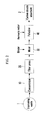
- FIG. 1 is a flowchart of a method of manufacturing a carbon dioxide adsorbent according to an exemplary embodiment of the present invention.
- FIG. 2 is a block diagram showing apparatuses used in the method of manufacturing the carbon dioxide adsorbent according to the exemplary embodiment of the present invention.
- the ironmaking waste 1 is supplied to a concentrator 10. That is, the ironmaking waste 1 is concentrated (S120).
- the ironmaking waste 1 may be an ironmaking sludge generated in an ironmaking process.
- a concentration of iron (Fe) may be 40 to 60 % or a concentration of carbon may be less than 25%.
- the ironmaking waste 1 concentrated in the concentrator 10 is supplied to a filter press 20.
- the ironmaking waste 1 is subjected to dehydration treatment in the filter press 20 (S130).
- the dehydration treatment is performed so that the ironmaking waste 1 includes moisture in an amount of 8 %.
- the dehydration treatment is performed only in the case of the ironmaking waste 1 including moisture, and may be omitted in the case of the ironmaking waste 1 not including moisture.
- the ironmaking waste 1 subjected to the dehydration treatment is supplied to a mixer 30. Further, a binder is supplied to the mixer 30 to be mixed with the ironmaking waste 1 (S140).
- the binder may be cement or bentonite.
- the ironmaking waste 1 mixed with the binder is supplied to a pelletizer 40. Further, prepared ammonia is injected into the pelletizer 40.
- the pelletizer 40 manufactures a pellet where ammonia is adsorbed onto the ironmaking waste 1 (S150). A concentration of ammonia injected in the manufacturing of the pellet may be 5 to 30 wt%.
- the pellet is dried (S160). Further, a size of the pellet may be 1 to 25 mm. The drying of the pellet may be performed at room temperature.
- the pellet manufactured by the aforementioned method serves as a carbon dioxide adsorbent 2. That is, the pellet is supplied to an apparatus 50 for reducing carbon dioxide to reduce carbon dioxide.
- FIG. 3 is a schematic diagram of the apparatus for reducing carbon dioxide according to the exemplary embodiment of the present invention.
- the apparatus 50 for reducing carbon dioxide includes an adsorption apparatus 60, a regeneration apparatus 70, a pH measurement apparatus 80, a rotary chamber 90, and a condenser 100.
- the adsorption apparatus 60 adsorbs carbon dioxide included in an exhaust gas by using the adsorbent 2 manufactured by the method of manufacturing the carbon dioxide adsorbent 2 according to the exemplary embodiment of the present invention. That is, the adsorbent 2 and the exhaust gas including carbon dioxide are supplied to the adsorption apparatus 60, and the adsorbent 2 and the exhaust gas come into contact with each other to adsorb carbon dioxide included in the exhaust gas onto the adsorbent 2.
- the exhaust gas including carbon dioxide may be at least one exhaust gas of a blast furnace exhaust gas (blast furnace gas; BFG), a coke oven gas (COG), and a FINEX exhaust gas (FINEX off-gas; FOG).
- an internal temperature of the adsorption apparatus 60 may be room temperature to 30 C. Further, the exhaust gas from which carbon dioxide is removed according to adsorption of carbon dioxide onto the adsorbent 2 is separated into materials such as hydrogen (H 2 ), carbon monoxide (CO), and nitrogen (N 2 ). Hydrogen and carbon monoxide are used to reduce the iron ore, and nitrogen may be used as a gas for transporting of ironmaking.
- the regeneration apparatus 70 desorbs carbon dioxide adsorbed onto the adsorbent 2. That is, the adsorbent 2 onto which carbon dioxide is adsorbed while passing through the adsorption apparatus 60 is supplied to the regeneration apparatus 70. Further, in the regeneration apparatus 70, the adsorbent 2 onto which carbon dioxide is adsorbed is heated to desorb carbon dioxide. Ironmaking waste heat is used in the heating, and a heating temperature may be 100 C.
- the adsorption apparatus 60 and the regeneration apparatus 70 may be formed to have a fluidization channel shape. Adsorption reactivity of carbon dioxide may be improved and carbon dioxide may be adsorbed in a large quantity by circulating the adsorbent that is a solid particle between the adsorption apparatus 60 and the regeneration apparatus 70. Moreover, since it is unnecessary to add pressure and reduce the pressure, power consumption is reduced, and thus energy consumption for reducing carbon dioxide is reduced.
- the pH measurement apparatus 80 measures pH of the adsorbent 2. Further, whether the adsorbent 2 is to be reused is judged by comparing the measured pH of the adsorbent 2 to a set value. If the pH of the adsorbent 2 is more than the set value, the adsorbent 2 is reused, and if the pH of the adsorbent 2 is not more than the set value, the adsorbent 2 is used to manufacture a reduced iron (direct reduced iron; DRI).
- the set value may be pH 10.
- the rotary chamber 90 receives the adsorbent 2 from the pH measurement apparatus 80 to spray ammonia onto the adsorbent 2.
- the adsorbent 2 onto which ammonia is adsorbed while passing through the rotary chamber 90 is supplied to the adsorption apparatus 60 to be reused. That is, the adsorbent 2 where the pH measured in the pH measurement apparatus 80 is more than the set value is supplied to the rotary chamber 90.
- the condenser 100 receives carbon dioxide desorbed from the regeneration apparatus 70.
- compounds of carbon dioxide and ammonia are desorbed. That is, the compounds of carbon dioxide and ammonia are supplied to the condenser 100.
- the condenser 100 separates the compounds into carbon dioxide and ammonia.
- separated ammonia is supplied to the rotary chamber 90 to be used as ammonia sprayed onto the adsorbent 2.
- Separated carbon dioxide may be discharged to the outside, or may be reused in a CO 2 reforming process or a reverse water gas shift reaction process to manufacture hydrogen and carbon monoxide. As described above, hydrogen and carbon monoxide may be used to reduce the iron ore.
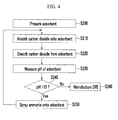
- FIG. 4 is a flowchart of a method of reducing carbon dioxide according to the exemplary embodiment of the present invention.
- the adsorbent 2 manufactured by the method of manufacturing the carbon dioxide adsorbent 2 according to the exemplary embodiment of the present invention is prepared (S200)
- the adsorbent 2 is supplied to the adsorption apparatus 60 to which the exhaust gas including carbon dioxide is supplied to adsorb carbon dioxide of the exhaust gas onto the adsorbent 2 (S210).
- the adsorbent 2 onto which carbon dioxide of the exhaust gas is adsorbed is supplied to the regeneration apparatus 70, and the regeneration apparatus 70 desorbs carbon dioxide from the adsorbent 2 by heating the adsorbent 2 onto which carbon dioxide of the exhaust gas is adsorbed by using ironmaking waste heat (S220).
- desorption of carbon dioxide may be performed by desorbing the compounds of ammonia and carbon dioxide adsorbed onto the adsorbent 2.
- the adsorbent 2 from which carbon dioxide is desorbed is supplied to the pH measurement apparatus 80, and the pH measurement apparatus 80 measures the pH of the adsorbent 2 (S230). Further, the pH measurement apparatus 80 judges whether the pH of the adsorbent 2 is more than the set value (S240).
- the set value of the pH may be pH10.
- the pH measurement apparatus 80 supplies the adsorbent 2 from which carbon dioxide is desorbed to the rotary chamber 90. Further, ammonia is sprayed onto the adsorbent 2 supplied to the rotary chamber 90 (S250).
- ammonia supplied to the rotary chamber 90 after the compounds of ammonia and carbon dioxide are separated into ammonia and carbon dioxide in the condenser 100 is used as sprayed ammonia.
- the adsorbent 2 from which carbon dioxide is desorbed is used to manufacture the reduced iron (S260).
Landscapes
- Chemical & Material Sciences (AREA)
- Chemical Kinetics & Catalysis (AREA)
- Engineering & Computer Science (AREA)
- Organic Chemistry (AREA)
- Analytical Chemistry (AREA)
- Combustion & Propulsion (AREA)
- General Chemical & Material Sciences (AREA)
- Oil, Petroleum & Natural Gas (AREA)
- Environmental & Geological Engineering (AREA)
- Health & Medical Sciences (AREA)
- Biomedical Technology (AREA)
- Thermal Sciences (AREA)
- Physics & Mathematics (AREA)
- Inorganic Chemistry (AREA)
- Treating Waste Gases (AREA)
- Solid-Sorbent Or Filter-Aiding Compositions (AREA)
- Carbon And Carbon Compounds (AREA)
Abstract
Description
- The present invention relates to an adsorbent collecting carbon dioxide, and more particularly, to a method of manufacturing a carbon dioxide adsorbent, and a method and an apparatus for reducing carbon dioxide.
- Carbon dioxide generated when fossil fuel is combusted is a representative greenhouse gas causing global warming, and recently, regulations on discharge thereof have become stricter. A gas containing a large amount of carbon dioxide, such as a combustion exhaust gas or a blast furnace gas, generated in an iron works is added to a general pressure swing adsorption (PSA) process to collect and recover carbon dioxide.
- A general pressure adsorption device is constituted by an adsorption column collecting carbon dioxide by using an adsorbent, and a regeneration column applying heat to the adsorbent collecting carbon dioxide to regenerate the adsorbent. The regenerated adsorbent is supplied back to the adsorption column to participate in a reaction. The adsorbent used for a predetermined period or more so that it loses an active site is discarded, and a replacement amount of adsorbent is added to the adsorption column.
- In the pressure swing adsorption process, a solid adsorbent such as activated carbon, silica, and alumina is used as the adsorbent, and carbon dioxide is collected by a physical adsorption method. However, this method has limitations in that, since the commercially available adsorbent is costly, an operation cost is high, and since the physical adsorption method is used, bonding force is weak, and thus collection efficiency of carbon dioxide at a large capacity and a high concentration is low.
- The above information disclosed in this Background section is only for enhancement of understanding of the background of the invention and therefore it may contain information that does not form the prior art that is already known in this country to a person of ordinary skill in the art.
- The present invention has been made in an effort to provide a method of manufacturing a carbon dioxide adsorbent, which has a low manufacturing cost and an excellent carbon dioxide collection effect, and a method and an apparatus of reducing carbon dioxide, to which the adsorbent is applied.
- An exemplary embodiment of the present invention provides a method of manufacturing a carbon dioxide adsorbent, including: providing ironmaking waste; mixing the ironmaking waste and a binder; manufacturing a pellet by injecting ammonia into the ironmaking waste mixed with the binder; and drying the pellet.
- A concentration of ammonia injected in the manufacturing of the pellet may be 5 to 30 wt%.
- The method may further include performing concentration and dehydration treatment before the ironmaking waste is mixed with the binder.
- A filter press may be used in the dehydration treatment.
- The ironmaking waste subjected to the dehydration treatment may include moisture in an amount of 8 %.
- The binder may be cement or bentonite.
- A size of the pellet may be 1 to 25 mm.
- Another exemplary embodiment of the present invention provides an apparatus for reducing carbon dioxide, including: an adsorption apparatus adopting an adsorbent manufactured by the method of any one of claims 1 to 7, blowing an exhaust gas including carbon dioxide and adsorbing carbon dioxide included in the exhaust gas onto the adsorbent; a regeneration apparatus applying heat to the adsorbent onto which carbon dioxide is adsorbed while passing through the adsorption apparatus to desorb adsorbed carbon dioxide; a pH measurement apparatus measuring pH of the adsorbent from which carbon dioxide is desorbed while passing through the regeneration apparatus; and a rotary chamber spraying ammonia onto the adsorbent passing through the pH measurement apparatus, in which the pH measurement apparatus selectively supplies the adsorbent according to the measured pH to the rotary chamber.
- Ironmaking waste heat may be used in the regeneration apparatus to supply heat to the adsorbent.
- If the pH measured in the pH measurement apparatus is more than 10, the adsorbent may be supplied to the rotary chamber, and if the pH measured in the pH measurement apparatus is 10 or less, the adsorbent may be recycled to manufacture reduced iron.
- The apparatus may further include a condenser for receiving compounds of ammonia and carbon dioxide desorbed from the regeneration apparatus to separate the compounds into ammonia and carbon dioxide by using a difference in condensation temperatures.
- The ammonia separated in the condenser may be supplied to the rotary chamber.
- The exhaust gas including carbon dioxide may be at least one selected from a blast furnace exhaust gas (BFG), a coke oven gas (COG), and a FINEX exhaust gas (FOG).
- Yet another exemplary embodiment of the present invention provides a method of reducing carbon dioxide, to which an adsorbent manufactured by the method of any one of claims 1 to 7 is applied, including: adsorbing carbon dioxide from an exhaust gas by bringing the exhaust gas including carbon dioxide into contact with the adsorbent; desorbing the carbon dioxide adsorbed onto the adsorbent; judging whether pH of the adsorbent from which the carbon dioxide is desorbed is more than a set value; and if the pH of the adsorbent is more than the set value, spraying ammonia onto the adsorbent, wherein the adsorbing of carbon dioxide to the spraying of ammonia are performed again by using the adsorbent onto which the ammonia is sprayed.
- Ironmaking waste heat may be used to desorb the carbon dioxide.
- If the pH of the adsorbent is not more than the set value, the adsorbent may be recycled to manufacture reduced iron.
- The set value of the pH may be 10.
- Compounds of the ammonia and the carbon dioxide may be desorbed when the carbon dioxide adsorbed onto the adsorbent is desorbed, and the method may further include separating the compounds into the ammonia and the carbon dioxide.
- The separated ammonia may be used in the spraying of ammonia onto the adsorbent.
- The exhaust gas including carbon dioxide may be at least one selected from a blast furnace exhaust gas (BFG), a coke oven gas (COG), and a FINEX exhaust gas (FOG).
- Still another exemplary embodiment of the present invention provides a carbon dioxide adsorbent manufactured by the method of any one of claims 1 to 7 and carrying ammonia.
- A concentration of iron of an ironmaking waste used in the manufacturing may be 40 to 60 %.
- A concentration of carbon of the ironmaking waste used in the manufacturing may be less than 25 %.
- Its size may be 1 to 25 mm.
- According to the exemplary embodiments of the present invention, since carbon dioxide is collected by using a chemical absorption reaction, it is possible to increase collection efficiency of carbon dioxide as compared to an existing physical adsorbent. Further, since desorption reactivity of carbon dioxide is improved, efficiency is increased.
- Further, it is possible to reduce a manufacturing cost by manufacturing a low-priced adsorbent.
-
-
FIG. 1 is a flowchart of a method of manufacturing a carbon dioxide adsorbent according to an exemplary embodiment of the present invention. -
FIG. 2 is a block diagram showing apparatuses used in the method of manufacturing the carbon dioxide adsorbent according to the exemplary embodiment of the present invention. -
FIG. 3 is a schematic diagram of an apparatus for reducing carbon dioxide according to the exemplary embodiment of the present invention. -
FIG. 4 is a flowchart of a method of reducing carbon dioxide according to the exemplary embodiment of the present invention. - An exemplary embodiment of the present invention will hereinafter be described in detail with reference to the accompanying drawings.
-
FIG. 1 is a flowchart of a method of manufacturing a carbon dioxide adsorbent according to an exemplary embodiment of the present invention. Further,FIG. 2 is a block diagram showing apparatuses used in the method of manufacturing the carbon dioxide adsorbent according to the exemplary embodiment of the present invention. - As illustrated in
FIGS. 1 and2 , if ammonia (NH3) is prepared (S100) and ironmaking waste 1 is provided (S110), the ironmaking waste 1 is supplied to aconcentrator 10. That is, the ironmaking waste 1 is concentrated (S120). Herein, the ironmaking waste 1 may be an ironmaking sludge generated in an ironmaking process. Meanwhile, in the provided ironmaking waste 1, a concentration of iron (Fe) may be 40 to 60 % or a concentration of carbon may be less than 25%. - The ironmaking waste 1 concentrated in the
concentrator 10 is supplied to afilter press 20. The ironmaking waste 1 is subjected to dehydration treatment in the filter press 20 (S130). The dehydration treatment is performed so that the ironmaking waste 1 includes moisture in an amount of 8 %. Of course the dehydration treatment is performed only in the case of the ironmaking waste 1 including moisture, and may be omitted in the case of the ironmaking waste 1 not including moisture. - The ironmaking waste 1 subjected to the dehydration treatment is supplied to a
mixer 30. Further, a binder is supplied to themixer 30 to be mixed with the ironmaking waste 1 (S140). Herein, the binder may be cement or bentonite. - The ironmaking waste 1 mixed with the binder is supplied to a
pelletizer 40. Further, prepared ammonia is injected into thepelletizer 40. Thepelletizer 40 manufactures a pellet where ammonia is adsorbed onto the ironmaking waste 1 (S150). A concentration of ammonia injected in the manufacturing of the pellet may be 5 to 30 wt%. - When the pellet is manufactured in the
pelletizer 40, the pellet is dried (S160). Further, a size of the pellet may be 1 to 25 mm. The drying of the pellet may be performed at room temperature. The pellet manufactured by the aforementioned method serves as acarbon dioxide adsorbent 2. That is, the pellet is supplied to anapparatus 50 for reducing carbon dioxide to reduce carbon dioxide. -
FIG. 3 is a schematic diagram of the apparatus for reducing carbon dioxide according to the exemplary embodiment of the present invention. - As illustrated in
FIG. 3 , theapparatus 50 for reducing carbon dioxide according to the exemplary embodiment of the present invention includes anadsorption apparatus 60, aregeneration apparatus 70, a pH measurement apparatus 80, arotary chamber 90, and acondenser 100. - The
adsorption apparatus 60 adsorbs carbon dioxide included in an exhaust gas by using theadsorbent 2 manufactured by the method of manufacturing thecarbon dioxide adsorbent 2 according to the exemplary embodiment of the present invention. That is, theadsorbent 2 and the exhaust gas including carbon dioxide are supplied to theadsorption apparatus 60, and theadsorbent 2 and the exhaust gas come into contact with each other to adsorb carbon dioxide included in the exhaust gas onto theadsorbent 2. Herein, the exhaust gas including carbon dioxide may be at least one exhaust gas of a blast furnace exhaust gas (blast furnace gas; BFG), a coke oven gas (COG), and a FINEX exhaust gas (FINEX off-gas; FOG). Meanwhile, an internal temperature of theadsorption apparatus 60 may be room temperature to 30 C. Further, the exhaust gas from which carbon dioxide is removed according to adsorption of carbon dioxide onto theadsorbent 2 is separated into materials such as hydrogen (H2), carbon monoxide (CO), and nitrogen (N2). Hydrogen and carbon monoxide are used to reduce the iron ore, and nitrogen may be used as a gas for transporting of ironmaking. - The
regeneration apparatus 70 desorbs carbon dioxide adsorbed onto theadsorbent 2. That is, theadsorbent 2 onto which carbon dioxide is adsorbed while passing through theadsorption apparatus 60 is supplied to theregeneration apparatus 70. Further, in theregeneration apparatus 70, theadsorbent 2 onto which carbon dioxide is adsorbed is heated to desorb carbon dioxide. Ironmaking waste heat is used in the heating, and a heating temperature may be 100 C. - Meanwhile, the
adsorption apparatus 60 and theregeneration apparatus 70 may be formed to have a fluidization channel shape. Adsorption reactivity of carbon dioxide may be improved and carbon dioxide may be adsorbed in a large quantity by circulating the adsorbent that is a solid particle between theadsorption apparatus 60 and theregeneration apparatus 70. Moreover, since it is unnecessary to add pressure and reduce the pressure, power consumption is reduced, and thus energy consumption for reducing carbon dioxide is reduced. - The pH measurement apparatus 80 measures pH of the
adsorbent 2. Further, whether theadsorbent 2 is to be reused is judged by comparing the measured pH of the adsorbent 2 to a set value. If the pH of theadsorbent 2 is more than the set value, theadsorbent 2 is reused, and if the pH of theadsorbent 2 is not more than the set value, theadsorbent 2 is used to manufacture a reduced iron (direct reduced iron; DRI). Herein, the set value may bepH 10. - Meanwhile, as described above, it is easy to replace the initially supplied
adsorbent 2 according to selective reuse of theadsorbent 2. That is, supplying of carbon dioxide does not need to be stopped, and a replacement cost of theadsorbent 2 is not accrued. - The
rotary chamber 90 receives the adsorbent 2 from the pH measurement apparatus 80 to spray ammonia onto theadsorbent 2. Theadsorbent 2 onto which ammonia is adsorbed while passing through therotary chamber 90 is supplied to theadsorption apparatus 60 to be reused. That is, theadsorbent 2 where the pH measured in the pH measurement apparatus 80 is more than the set value is supplied to therotary chamber 90. - The
condenser 100 receives carbon dioxide desorbed from theregeneration apparatus 70. When carbon dioxide is desorbed from theregeneration apparatus 70, compounds of carbon dioxide and ammonia are desorbed. That is, the compounds of carbon dioxide and ammonia are supplied to thecondenser 100. Moreover, thecondenser 100 separates the compounds into carbon dioxide and ammonia. Herein, separated ammonia is supplied to therotary chamber 90 to be used as ammonia sprayed onto theadsorbent 2. Separated carbon dioxide may be discharged to the outside, or may be reused in a CO2 reforming process or a reverse water gas shift reaction process to manufacture hydrogen and carbon monoxide. As described above, hydrogen and carbon monoxide may be used to reduce the iron ore. -
FIG. 4 is a flowchart of a method of reducing carbon dioxide according to the exemplary embodiment of the present invention. - As illustrated in
FIG. 4 , if the adsorbent 2 manufactured by the method of manufacturing thecarbon dioxide adsorbent 2 according to the exemplary embodiment of the present invention is prepared (S200), theadsorbent 2 is supplied to theadsorption apparatus 60 to which the exhaust gas including carbon dioxide is supplied to adsorb carbon dioxide of the exhaust gas onto the adsorbent 2 (S210). - The
adsorbent 2 onto which carbon dioxide of the exhaust gas is adsorbed is supplied to theregeneration apparatus 70, and theregeneration apparatus 70 desorbs carbon dioxide from theadsorbent 2 by heating theadsorbent 2 onto which carbon dioxide of the exhaust gas is adsorbed by using ironmaking waste heat (S220). Herein, desorption of carbon dioxide may be performed by desorbing the compounds of ammonia and carbon dioxide adsorbed onto theadsorbent 2. - The adsorbent 2 from which carbon dioxide is desorbed is supplied to the pH measurement apparatus 80, and the pH measurement apparatus 80 measures the pH of the adsorbent 2 (S230). Further, the pH measurement apparatus 80 judges whether the pH of the
adsorbent 2 is more than the set value (S240). Herein, the set value of the pH may be pH10. - If the pH of the
adsorbent 2 is judged to be more than the set value, the pH measurement apparatus 80 supplies the adsorbent 2 from which carbon dioxide is desorbed to therotary chamber 90. Further, ammonia is sprayed onto theadsorbent 2 supplied to the rotary chamber 90 (S250). Herein, ammonia supplied to therotary chamber 90 after the compounds of ammonia and carbon dioxide are separated into ammonia and carbon dioxide in thecondenser 100 is used as sprayed ammonia. - If the pH of the
adsorbent 2 is judged to be not more than the set value, the adsorbent 2 from which carbon dioxide is desorbed is used to manufacture the reduced iron (S260). - According to the exemplary embodiments of the present invention, since carbon dioxide is collected by using a chemical absorption reaction, it is possible to increase collection efficiency of carbon dioxide as compared to an existing physical adsorbent. Further, since desorption reactivity of carbon dioxide is improved, efficiency is increased. Moreover, it is possible to reduce a manufacturing cost by manufacturing the low-priced
adsorbent 2. - While this invention has been described in connection with what is presently considered to be practical exemplary embodiments, it is to be understood that the invention is not limited to the disclosed embodiments. On the contrary, it is intended to cover various modifications and equivalent arrangements included within the spirit and scope of the appended claims.
Claims (24)
- A method of manufacturing a carbon dioxide adsorbent, comprising:providing ironmaking waste;mixing the ironmaking waste and a binder;manufacturing a pellet by injecting ammonia into the ironmaking waste mixed with the binder; anddrying the pellet.
- The method of claim 1, wherein
a concentration of ammonia injected in the manufacturing of the pellet is 5 to 30 wt%. - The method of claim 1, further comprising
performing concentration and dehydration treatment before the ironmaking waste is mixed with the binder. - The method of claim 3, wherein
a filter press is used in the dehydration treatment. - The method of claim 3, wherein
the ironmaking waste subjected to the dehydration treatment includes moisture in an amount of 8 %. - The method of claim 1, wherein
the binder is cement or bentonite. - The method of claim 1, wherein
a size of the pellet is 1 to 25 mm. - An apparatus of reducing carbon dioxide, comprising:an adsorption apparatus adopting an adsorbent manufactured by the method of any one of claims 1 to 7, blowing an exhaust gas including carbon dioxide and adsorbing carbon dioxide included in the exhaust gas onto the adsorbent;a regeneration apparatus applying heat to the adsorbent onto which carbon dioxide is adsorbed while passing through the adsorption apparatus to desorb the adsorbed carbon dioxide;a pH measurement apparatus measuring pH of the adsorbent from which carbon dioxide is desorbed while passing through the regeneration apparatus; anda rotary chamber spraying ammonia onto the adsorbent passing through the pH measurement apparatus,wherein the pH measurement apparatus selectively supplies the adsorbent according to the measured pH to the rotary chamber.
- The apparatus of claim 8, wherein
ironmaking waste heat is used in the regeneration apparatus to supply heat to the adsorbent. - The apparatus of claim 8, wherein
if the pH measured in the pH measurement apparatus is more than 10, the adsorbent is supplied to the rotary chamber, and
if the pH measured in the pH measurement apparatus is 10 or less, the adsorbent is recycled to manufacture reduced iron. - The apparatus of claim 8, further comprising
a condenser for receiving compounds of ammonia and carbon dioxide desorbed from the regeneration apparatus to separate the compounds into ammonia and carbon dioxide by using a difference in condensation temperatures. - The apparatus of claim 11, wherein
the ammonia separated in the condenser is supplied to the rotary chamber. - The apparatus of claim 8, wherein
the exhaust gas including carbon dioxide is at least one selected from a blast furnace exhaust gas (BFG), a coke oven gas (COG), and a FINEX exhaust gas (FOG). - A method of reducing carbon dioxide, to which an adsorbent manufactured by the method of any one of claims 1 to 7 is applied, comprising:adsorbing carbon dioxide from an exhaust gas by bringing the exhaust gas including carbon dioxide into contact with the adsorbent;desorbing the carbon dioxide adsorbed onto the adsorbent;judging whether pH of the adsorbent from which the carbon dioxide is desorbed is more than a set value; andif the pH of the adsorbent is more than the set value, spraying ammonia onto the adsorbent,wherein the adsorbing of carbon dioxide to the spraying of ammonia are performed again by using the adsorbent onto which ammonia is sprayed.
- The method of claim 14, wherein
ironmaking waste heat is used to desorb the carbon dioxide. - The method of claim 14, wherein
if the pH of the adsorbent is not more than the set value, the adsorbent is recycled to manufacture reduced iron. - The method of claim 14, wherein
the set value of the pH is 10. - The method of claim 14, wherein
compounds of the ammonia and the carbon dioxide are desorbed when the carbon dioxide adsorbed onto the adsorbent is desorbed, and
the method further comprises separating the compounds into the ammonia and the carbon dioxide. - The method of claim 18, wherein
the separated ammonia is used in the spraying of ammonia onto the adsorbent. - The method of claim 14, wherein
the exhaust gas including carbon dioxide is at least one selected from a blast furnace exhaust gas (BFG), a coke oven gas (COG), and a FINEX exhaust gas (FOG). - A carbon dioxide adsorbent manufactured by the method of any one of claims 1 to 7 and carrying ammonia.
- The carbon dioxide adsorbent of claim 21, wherein
a concentration of iron of ironmaking waste used in the manufacturing is 40 to 60 %. - The carbon dioxide adsorbent of claim 21, wherein
a concentration of carbon of the ironmaking waste used in the manufacturing is less than 25 %. - The carbon dioxide adsorbent of claim 21, wherein
its size is 1 to 25 mm.
Applications Claiming Priority (2)
| Application Number | Priority Date | Filing Date | Title |
|---|---|---|---|
| KR1020110143751A KR101353595B1 (en) | 2011-12-27 | 2011-12-27 | Co2 gas reducing method and system thereof |
| PCT/KR2012/006808 WO2013100306A1 (en) | 2011-12-27 | 2012-08-27 | Method for manufacturing a carbon dioxide adsorbent, method for reducing carbon dioxide and apparatus for same |
Publications (3)
| Publication Number | Publication Date |
|---|---|
| EP2799130A1 true EP2799130A1 (en) | 2014-11-05 |
| EP2799130A4 EP2799130A4 (en) | 2015-07-22 |
| EP2799130B1 EP2799130B1 (en) | 2017-08-02 |
Family
ID=48697741
Family Applications (1)
| Application Number | Title | Priority Date | Filing Date |
|---|---|---|---|
| EP12862508.4A Not-in-force EP2799130B1 (en) | 2011-12-27 | 2012-08-27 | Method for manufacturing a carbon dioxide adsorbent, method for reducing carbon dioxide and apparatus for same |
Country Status (4)
| Country | Link |
|---|---|
| EP (1) | EP2799130B1 (en) |
| KR (1) | KR101353595B1 (en) |
| CN (1) | CN104023839B (en) |
| WO (1) | WO2013100306A1 (en) |
Families Citing this family (3)
| Publication number | Priority date | Publication date | Assignee | Title |
|---|---|---|---|---|
| KR102128428B1 (en) * | 2018-12-27 | 2020-06-30 | 성신양회 주식회사 | Carbon dioxide capture device in exhaust gas of cement calcination process |
| KR102325364B1 (en) * | 2019-05-17 | 2021-11-11 | 한국전력공사 | Automatic control apparatus for acid gas capture |
| CN118079860A (en) * | 2024-04-02 | 2024-05-28 | 中国船舶集团有限公司第七一九研究所 | A preparation method and preparation device of dry quenching coal slag adsorbent for CO2 adsorption |
Family Cites Families (9)
| Publication number | Priority date | Publication date | Assignee | Title |
|---|---|---|---|---|
| JPS5317998B2 (en) * | 1972-05-02 | 1978-06-12 | ||
| JPH0788362A (en) * | 1993-08-27 | 1995-04-04 | Tohoku Electric Power Co Inc | Gaseous carbon dioxide adsorbent |
| KR100282211B1 (en) * | 1999-05-20 | 2001-02-15 | 양금모 | A method of producing for microbial support by low temperature-calcining for biological wastewater treatment |
| KR100769218B1 (en) * | 2005-04-15 | 2007-10-23 | 고등기술연구원연구조합 | Adsorbent using slag generated in waste melting process and its manufacturing method |
| EP2481472B1 (en) * | 2006-03-10 | 2014-08-20 | C-Quest Technologies International LLC | Carbon dioxide sequestration process for cement manufactoring facilities |
| CN101641145B (en) * | 2007-02-20 | 2014-05-07 | R·J·安维科 | System, apparatus and method for carbon dioxide sequestration |
| US8496897B2 (en) * | 2007-02-20 | 2013-07-30 | Richard J Hunwick | System, apparatus and method for carbon dioxide sequestration |
| EP2175967B1 (en) * | 2007-06-22 | 2015-04-08 | Commonwealth Scientific and Industrial Research Organisation | An improved method for co2 transfer from gas streams to ammonia solutions |
| WO2011130129A1 (en) * | 2010-04-13 | 2011-10-20 | Conocophillips Company | Ammonia salts as regenerable co2 sorbents |
-
2011
- 2011-12-27 KR KR1020110143751A patent/KR101353595B1/en active Active
-
2012
- 2012-08-27 CN CN201280064320.2A patent/CN104023839B/en active Active
- 2012-08-27 WO PCT/KR2012/006808 patent/WO2013100306A1/en not_active Ceased
- 2012-08-27 EP EP12862508.4A patent/EP2799130B1/en not_active Not-in-force
Also Published As
| Publication number | Publication date |
|---|---|
| CN104023839B (en) | 2016-03-23 |
| WO2013100306A1 (en) | 2013-07-04 |
| EP2799130A4 (en) | 2015-07-22 |
| CN104023839A (en) | 2014-09-03 |
| KR20130075398A (en) | 2013-07-05 |
| EP2799130B1 (en) | 2017-08-02 |
| KR101353595B1 (en) | 2014-02-13 |
Similar Documents
| Publication | Publication Date | Title |
|---|---|---|
| CN111569603A (en) | A flue gas integrated desulfurization and denitrification method based on the principle of low temperature adsorption | |
| CN103463946B (en) | Based on the sintering gas purifying method of heat sinter catalytic action | |
| CN102019135A (en) | Flue gas-based combined desulfuration and denitration method and special device for method | |
| CN102266702A (en) | Method for capturing ammonia in industrial waste gas and equipment and application thereof | |
| JP2009108241A (en) | Blast furnace gas calorie increase method | |
| CN106621773A (en) | Ammonia-carbon combined desulfurization and denitration method for sintering flue gas | |
| CN205461790U (en) | A SOx/NOx control device for coke oven gas cleaning | |
| CN111569604A (en) | A low-temperature adsorption desulfurization method for flue gas | |
| CN110352090A (en) | Carbon dioxide removal device, and method for restoring carbon dioxide adsorption capacity of adsorbent | |
| EP2799130B1 (en) | Method for manufacturing a carbon dioxide adsorbent, method for reducing carbon dioxide and apparatus for same | |
| CN108472571A (en) | Carbon dioxide separation retracting device, using its combustion system and thermal power generation system and carbon dioxide separation and recovery method | |
| JP6671204B2 (en) | Gas separation equipment | |
| Fang et al. | Chemical adsorption of nitrogen dioxide with an activated carbon adsorption system | |
| CN102019143B (en) | Method for joint desulfurization and denitration of flue gas and special device thereof | |
| CN103212271B (en) | Gas separating system and method for separating gas by using system thereof | |
| KR100941399B1 (en) | Apparatus and method for processing exhaust gas | |
| CN102512905A (en) | Emission reduction method for tail gas in sulfuric acid production | |
| CN111093800B (en) | Temperature swing adsorption process | |
| CN104785082A (en) | Sintered pellet flue gas absorption-desorption integration tower | |
| WO2025139245A1 (en) | Method for synergistically capturing carbon dioxide in sintering flue gas and treating multiple pollutants | |
| CN101318124A (en) | A kind of preparation method of molecular sieve adsorbent for purifying low-concentration phosphine | |
| CN116099339B (en) | Nitrogen oxide-containing flue gas adsorption and removal device and removal method | |
| CN108744960B (en) | Device and method for simultaneous desulfurization, denitrification, mercury removal and resource utilization of flue gas | |
| KR20250096436A (en) | Metal-organic framework for the separation of carbon monoxide and use thereof | |
| JP4015829B2 (en) | Method for producing activated carbon having high strength and high denitration performance |
Legal Events
| Date | Code | Title | Description |
|---|---|---|---|
| PUAI | Public reference made under article 153(3) epc to a published international application that has entered the european phase |
Free format text: ORIGINAL CODE: 0009012 |
|
| 17P | Request for examination filed |
Effective date: 20140725 |
|
| AK | Designated contracting states |
Kind code of ref document: A1 Designated state(s): AL AT BE BG CH CY CZ DE DK EE ES FI FR GB GR HR HU IE IS IT LI LT LU LV MC MK MT NL NO PL PT RO RS SE SI SK SM TR |
|
| RIN1 | Information on inventor provided before grant (corrected) |
Inventor name: KIM, SUNG-MAN Inventor name: LEE, SEUNGMOON Inventor name: JUNG, JONGHWUN Inventor name: KIM, KI HYUN |
|
| DAX | Request for extension of the european patent (deleted) | ||
| RAP1 | Party data changed (applicant data changed or rights of an application transferred) |
Owner name: POSCO |
|
| RA4 | Supplementary search report drawn up and despatched (corrected) |
Effective date: 20150624 |
|
| RIC1 | Information provided on ipc code assigned before grant |
Ipc: C10K 1/26 20060101ALI20150618BHEP Ipc: B01D 53/04 20060101ALI20150618BHEP Ipc: B01J 20/30 20060101AFI20150618BHEP Ipc: B01D 53/62 20060101ALI20150618BHEP Ipc: C10K 1/20 20060101ALI20150618BHEP |
|
| GRAP | Despatch of communication of intention to grant a patent |
Free format text: ORIGINAL CODE: EPIDOSNIGR1 |
|
| STAA | Information on the status of an ep patent application or granted ep patent |
Free format text: STATUS: GRANT OF PATENT IS INTENDED |
|
| INTG | Intention to grant announced |
Effective date: 20170216 |
|
| GRAS | Grant fee paid |
Free format text: ORIGINAL CODE: EPIDOSNIGR3 |
|
| GRAA | (expected) grant |
Free format text: ORIGINAL CODE: 0009210 |
|
| STAA | Information on the status of an ep patent application or granted ep patent |
Free format text: STATUS: THE PATENT HAS BEEN GRANTED |
|
| AK | Designated contracting states |
Kind code of ref document: B1 Designated state(s): AL AT BE BG CH CY CZ DE DK EE ES FI FR GB GR HR HU IE IS IT LI LT LU LV MC MK MT NL NO PL PT RO RS SE SI SK SM TR |
|
| REG | Reference to a national code |
Ref country code: CH Ref legal event code: EP Ref country code: AT Ref legal event code: REF Ref document number: 913854 Country of ref document: AT Kind code of ref document: T Effective date: 20170815 |
|
| REG | Reference to a national code |
Ref country code: IE Ref legal event code: FG4D |
|
| REG | Reference to a national code |
Ref country code: FR Ref legal event code: PLFP Year of fee payment: 6 |
|
| REG | Reference to a national code |
Ref country code: DE Ref legal event code: R096 Ref document number: 602012035484 Country of ref document: DE |
|
| REG | Reference to a national code |
Ref country code: SE Ref legal event code: TRGR |
|
| PGFP | Annual fee paid to national office [announced via postgrant information from national office to epo] |
Ref country code: FR Payment date: 20170829 Year of fee payment: 6 Ref country code: DE Payment date: 20170822 Year of fee payment: 6 |
|
| REG | Reference to a national code |
Ref country code: NL Ref legal event code: FP |
|
| PGFP | Annual fee paid to national office [announced via postgrant information from national office to epo] |
Ref country code: SE Payment date: 20170829 Year of fee payment: 6 Ref country code: NL Payment date: 20170911 Year of fee payment: 6 |
|
| REG | Reference to a national code |
Ref country code: AT Ref legal event code: MK05 Ref document number: 913854 Country of ref document: AT Kind code of ref document: T Effective date: 20170802 |
|
| REG | Reference to a national code |
Ref country code: LT Ref legal event code: MG4D |
|
| PG25 | Lapsed in a contracting state [announced via postgrant information from national office to epo] |
Ref country code: NO Free format text: LAPSE BECAUSE OF FAILURE TO SUBMIT A TRANSLATION OF THE DESCRIPTION OR TO PAY THE FEE WITHIN THE PRESCRIBED TIME-LIMIT Effective date: 20171102 Ref country code: FI Free format text: LAPSE BECAUSE OF FAILURE TO SUBMIT A TRANSLATION OF THE DESCRIPTION OR TO PAY THE FEE WITHIN THE PRESCRIBED TIME-LIMIT Effective date: 20170802 Ref country code: HR Free format text: LAPSE BECAUSE OF FAILURE TO SUBMIT A TRANSLATION OF THE DESCRIPTION OR TO PAY THE FEE WITHIN THE PRESCRIBED TIME-LIMIT Effective date: 20170802 Ref country code: AT Free format text: LAPSE BECAUSE OF FAILURE TO SUBMIT A TRANSLATION OF THE DESCRIPTION OR TO PAY THE FEE WITHIN THE PRESCRIBED TIME-LIMIT Effective date: 20170802 Ref country code: LT Free format text: LAPSE BECAUSE OF FAILURE TO SUBMIT A TRANSLATION OF THE DESCRIPTION OR TO PAY THE FEE WITHIN THE PRESCRIBED TIME-LIMIT Effective date: 20170802 |
|
| PG25 | Lapsed in a contracting state [announced via postgrant information from national office to epo] |
Ref country code: ES Free format text: LAPSE BECAUSE OF FAILURE TO SUBMIT A TRANSLATION OF THE DESCRIPTION OR TO PAY THE FEE WITHIN THE PRESCRIBED TIME-LIMIT Effective date: 20170802 Ref country code: LV Free format text: LAPSE BECAUSE OF FAILURE TO SUBMIT A TRANSLATION OF THE DESCRIPTION OR TO PAY THE FEE WITHIN THE PRESCRIBED TIME-LIMIT Effective date: 20170802 Ref country code: GR Free format text: LAPSE BECAUSE OF FAILURE TO SUBMIT A TRANSLATION OF THE DESCRIPTION OR TO PAY THE FEE WITHIN THE PRESCRIBED TIME-LIMIT Effective date: 20171103 Ref country code: RS Free format text: LAPSE BECAUSE OF FAILURE TO SUBMIT A TRANSLATION OF THE DESCRIPTION OR TO PAY THE FEE WITHIN THE PRESCRIBED TIME-LIMIT Effective date: 20170802 Ref country code: PL Free format text: LAPSE BECAUSE OF FAILURE TO SUBMIT A TRANSLATION OF THE DESCRIPTION OR TO PAY THE FEE WITHIN THE PRESCRIBED TIME-LIMIT Effective date: 20170802 Ref country code: BG Free format text: LAPSE BECAUSE OF FAILURE TO SUBMIT A TRANSLATION OF THE DESCRIPTION OR TO PAY THE FEE WITHIN THE PRESCRIBED TIME-LIMIT Effective date: 20171102 Ref country code: IS Free format text: LAPSE BECAUSE OF FAILURE TO SUBMIT A TRANSLATION OF THE DESCRIPTION OR TO PAY THE FEE WITHIN THE PRESCRIBED TIME-LIMIT Effective date: 20171202 |
|
| REG | Reference to a national code |
Ref country code: CH Ref legal event code: PL |
|
| PG25 | Lapsed in a contracting state [announced via postgrant information from national office to epo] |
Ref country code: CH Free format text: LAPSE BECAUSE OF NON-PAYMENT OF DUE FEES Effective date: 20170831 Ref country code: RO Free format text: LAPSE BECAUSE OF FAILURE TO SUBMIT A TRANSLATION OF THE DESCRIPTION OR TO PAY THE FEE WITHIN THE PRESCRIBED TIME-LIMIT Effective date: 20170802 Ref country code: LI Free format text: LAPSE BECAUSE OF NON-PAYMENT OF DUE FEES Effective date: 20170831 Ref country code: DK Free format text: LAPSE BECAUSE OF FAILURE TO SUBMIT A TRANSLATION OF THE DESCRIPTION OR TO PAY THE FEE WITHIN THE PRESCRIBED TIME-LIMIT Effective date: 20170802 Ref country code: CZ Free format text: LAPSE BECAUSE OF FAILURE TO SUBMIT A TRANSLATION OF THE DESCRIPTION OR TO PAY THE FEE WITHIN THE PRESCRIBED TIME-LIMIT Effective date: 20170802 |
|
| REG | Reference to a national code |
Ref country code: DE Ref legal event code: R097 Ref document number: 602012035484 Country of ref document: DE |
|
| REG | Reference to a national code |
Ref country code: IE Ref legal event code: MM4A |
|
| PG25 | Lapsed in a contracting state [announced via postgrant information from national office to epo] |
Ref country code: MC Free format text: LAPSE BECAUSE OF FAILURE TO SUBMIT A TRANSLATION OF THE DESCRIPTION OR TO PAY THE FEE WITHIN THE PRESCRIBED TIME-LIMIT Effective date: 20170802 Ref country code: IT Free format text: LAPSE BECAUSE OF FAILURE TO SUBMIT A TRANSLATION OF THE DESCRIPTION OR TO PAY THE FEE WITHIN THE PRESCRIBED TIME-LIMIT Effective date: 20170802 Ref country code: SK Free format text: LAPSE BECAUSE OF FAILURE TO SUBMIT A TRANSLATION OF THE DESCRIPTION OR TO PAY THE FEE WITHIN THE PRESCRIBED TIME-LIMIT Effective date: 20170802 Ref country code: EE Free format text: LAPSE BECAUSE OF FAILURE TO SUBMIT A TRANSLATION OF THE DESCRIPTION OR TO PAY THE FEE WITHIN THE PRESCRIBED TIME-LIMIT Effective date: 20170802 Ref country code: SM Free format text: LAPSE BECAUSE OF FAILURE TO SUBMIT A TRANSLATION OF THE DESCRIPTION OR TO PAY THE FEE WITHIN THE PRESCRIBED TIME-LIMIT Effective date: 20170802 |
|
| REG | Reference to a national code |
Ref country code: BE Ref legal event code: MM Effective date: 20170831 |
|
| PLBE | No opposition filed within time limit |
Free format text: ORIGINAL CODE: 0009261 |
|
| STAA | Information on the status of an ep patent application or granted ep patent |
Free format text: STATUS: NO OPPOSITION FILED WITHIN TIME LIMIT |
|
| PG25 | Lapsed in a contracting state [announced via postgrant information from national office to epo] |
Ref country code: LU Free format text: LAPSE BECAUSE OF NON-PAYMENT OF DUE FEES Effective date: 20170827 |
|
| 26N | No opposition filed |
Effective date: 20180503 |
|
| GBPC | Gb: european patent ceased through non-payment of renewal fee |
Effective date: 20171102 |
|
| PG25 | Lapsed in a contracting state [announced via postgrant information from national office to epo] |
Ref country code: IE Free format text: LAPSE BECAUSE OF NON-PAYMENT OF DUE FEES Effective date: 20170827 |
|
| PG25 | Lapsed in a contracting state [announced via postgrant information from national office to epo] |
Ref country code: SI Free format text: LAPSE BECAUSE OF FAILURE TO SUBMIT A TRANSLATION OF THE DESCRIPTION OR TO PAY THE FEE WITHIN THE PRESCRIBED TIME-LIMIT Effective date: 20170802 Ref country code: BE Free format text: LAPSE BECAUSE OF NON-PAYMENT OF DUE FEES Effective date: 20170831 |
|
| PG25 | Lapsed in a contracting state [announced via postgrant information from national office to epo] |
Ref country code: MT Free format text: LAPSE BECAUSE OF NON-PAYMENT OF DUE FEES Effective date: 20170827 |
|
| PG25 | Lapsed in a contracting state [announced via postgrant information from national office to epo] |
Ref country code: GB Free format text: LAPSE BECAUSE OF NON-PAYMENT OF DUE FEES Effective date: 20171102 |
|
| REG | Reference to a national code |
Ref country code: DE Ref legal event code: R119 Ref document number: 602012035484 Country of ref document: DE |
|
| REG | Reference to a national code |
Ref country code: SE Ref legal event code: EUG |
|
| REG | Reference to a national code |
Ref country code: NL Ref legal event code: MM Effective date: 20180901 |
|
| PG25 | Lapsed in a contracting state [announced via postgrant information from national office to epo] |
Ref country code: SE Free format text: LAPSE BECAUSE OF NON-PAYMENT OF DUE FEES Effective date: 20180828 |
|
| PG25 | Lapsed in a contracting state [announced via postgrant information from national office to epo] |
Ref country code: NL Free format text: LAPSE BECAUSE OF NON-PAYMENT OF DUE FEES Effective date: 20180901 Ref country code: HU Free format text: LAPSE BECAUSE OF FAILURE TO SUBMIT A TRANSLATION OF THE DESCRIPTION OR TO PAY THE FEE WITHIN THE PRESCRIBED TIME-LIMIT; INVALID AB INITIO Effective date: 20120827 |
|
| PG25 | Lapsed in a contracting state [announced via postgrant information from national office to epo] |
Ref country code: DE Free format text: LAPSE BECAUSE OF NON-PAYMENT OF DUE FEES Effective date: 20190301 |
|
| PG25 | Lapsed in a contracting state [announced via postgrant information from national office to epo] |
Ref country code: FR Free format text: LAPSE BECAUSE OF NON-PAYMENT OF DUE FEES Effective date: 20180831 |
|
| PG25 | Lapsed in a contracting state [announced via postgrant information from national office to epo] |
Ref country code: CY Free format text: LAPSE BECAUSE OF FAILURE TO SUBMIT A TRANSLATION OF THE DESCRIPTION OR TO PAY THE FEE WITHIN THE PRESCRIBED TIME-LIMIT Effective date: 20170802 |
|
| PG25 | Lapsed in a contracting state [announced via postgrant information from national office to epo] |
Ref country code: MK Free format text: LAPSE BECAUSE OF FAILURE TO SUBMIT A TRANSLATION OF THE DESCRIPTION OR TO PAY THE FEE WITHIN THE PRESCRIBED TIME-LIMIT Effective date: 20170802 |
|
| PG25 | Lapsed in a contracting state [announced via postgrant information from national office to epo] |
Ref country code: TR Free format text: LAPSE BECAUSE OF FAILURE TO SUBMIT A TRANSLATION OF THE DESCRIPTION OR TO PAY THE FEE WITHIN THE PRESCRIBED TIME-LIMIT Effective date: 20170802 |
|
| PG25 | Lapsed in a contracting state [announced via postgrant information from national office to epo] |
Ref country code: PT Free format text: LAPSE BECAUSE OF FAILURE TO SUBMIT A TRANSLATION OF THE DESCRIPTION OR TO PAY THE FEE WITHIN THE PRESCRIBED TIME-LIMIT Effective date: 20170802 |
|
| PG25 | Lapsed in a contracting state [announced via postgrant information from national office to epo] |
Ref country code: AL Free format text: LAPSE BECAUSE OF FAILURE TO SUBMIT A TRANSLATION OF THE DESCRIPTION OR TO PAY THE FEE WITHIN THE PRESCRIBED TIME-LIMIT Effective date: 20170802 |