EP2798952A1 - Fishing reel - Google Patents
Fishing reel Download PDFInfo
- Publication number
- EP2798952A1 EP2798952A1 EP20140163094 EP14163094A EP2798952A1 EP 2798952 A1 EP2798952 A1 EP 2798952A1 EP 20140163094 EP20140163094 EP 20140163094 EP 14163094 A EP14163094 A EP 14163094A EP 2798952 A1 EP2798952 A1 EP 2798952A1
- Authority
- EP
- European Patent Office
- Prior art keywords
- loosening
- fishing reel
- lever part
- handle shaft
- handle
- Prior art date
- Legal status (The legal status is an assumption and is not a legal conclusion. Google has not performed a legal analysis and makes no representation as to the accuracy of the status listed.)
- Granted
Links
Images




Classifications
-
- A—HUMAN NECESSITIES
- A01—AGRICULTURE; FORESTRY; ANIMAL HUSBANDRY; HUNTING; TRAPPING; FISHING
- A01K—ANIMAL HUSBANDRY; AVICULTURE; APICULTURE; PISCICULTURE; FISHING; REARING OR BREEDING ANIMALS, NOT OTHERWISE PROVIDED FOR; NEW BREEDS OF ANIMALS
- A01K89/00—Reels
- A01K89/006—Hand crank features
Definitions
- the present invention relates to a fishing reel.
- a fishing reel is provided with a handle assembly for winding a fishing line.
- the handle assembly includes a handle arm and a handle knob.
- the handle arm is fixed to the tip portion of a handle shaft.
- the handle knob is mounted to the tip portion of the handle arm.
- a type of handle assembly has been also provided so far. This type of handle assembly is capable of changing the length of the handle arm.
- a fishing reel which is described in Japan Laid-open Patent Application Publication No. JP-A-2004-135624 , is configured to be capable of changing the length of the handle arm by manually tightening or loosening a nut member.
- a handle device for a fishing reel described in Japan Examined Utility Model Application Publication No. JP-Y-H03-10860 and that described in Japan Laid-open Patent Application Publication No. JP-A-2004-222559 are configured to be capable of changing the length of the handle arm by tightening or loosening a nut and a bolt through a rotational operation of the handle.
- the position of the handle arm attached onto the handle shaft is configured to be changed by loosening the nut and the bolt that fix the handle arm onto the handle shaft. Accordingly, it is possible to change the length of the handle arm.
- a fishing reel includes a reel unit, a handle shaft, a handle arm, a handle knob, a nut, and an anti-loosening member.
- the handle shaft is rotatably supported by the reel unit.
- the handle shaft includes an anti-loosening engaging portion and a male threaded portion on a tip portion thereof.
- the handle arm extends from a first end portion thereof to a second end portion thereof in a direction intersecting with the handle shaft.
- the handle arm includes an elongated hole in the first end portion thereof. The elongated hole extends in the direction.
- the handle shaft is inserted in the elongated hole to be non-rotatably engaged with the handle arm. A position of the shaft in the elongated hole being adjustable.
- the handle knob is rotatably attached to the second end portion of the handle arm.
- the nut member includes a female threaded portion.
- the female thread portion is screwed onto the male threaded portion of the handle shaft.
- the anti-loosening member is configured on the nut member and is being selectively set in a first position and a second position.
- the anti-loosening member is engaged with the anti-loosening engaging portion in the first position to prevent the nut member from loosening.
- the anti-loosening member is disengaged from the anti-loosening engaging portion in the second position to allow the nut member to rotate in the loosening direction.
- the handle arm is fixed onto the tip portion of the handle shaft by means of the nut member.
- the handle arm has the elongated hole, and the length of the handle arm can be changed by changing the fixed position of the handle shaft within the elongated hole.
- loosening of the nut member can be prevented by setting the anti-loosening member in the first position, while the handle arm is fixed onto the handle shaft.
- the nut member in changing the length of the handle arm, the nut member can be loosened by setting the anti-loosening member in the second position. Therefore, when the form of the nut member can be changed by a manual operation, for instance, tightening of the nut member can be easily performed by an angler, and loosening of the nut member can be prevented.
- a fishing reel according to a second aspect of the present invention relates to the fishing reel according to the first aspect.
- the fishing reel further includes a switch operation mechanism for performing an operation of switching the anti-loosening member between the first position and the second position.
- the anti-loosening member can be switched between the first position and the second position by the switch operation means.
- a fishing reel according to a third aspect of the present invention relates to the fishing reel according to the first or second aspect.
- the nut member includes a body part and a lever part.
- the body part is a member in which the female threaded portion is formed.
- the lever part is attached to the body part and is movable away from the body part.
- the anti-loosening member is configured to the lever part and includes a pawl.
- the pawl is configured to be engaged with the anti-loosening engaging portion when the lever part is attached to the body part.
- the pawl is configured to be disengaged from the anti-loosening engaging portion when the lever part is moved away from the body part.
- the pawl of the anti-loosening member mounted to the lever part is configured to be disengaged from the anti-loosening engaging portion of the handle shaft. Therefore, under the condition, the nut member can be loosened, and thus, it is possible to change the fixed position of the handle shaft with respect to the handle arm.
- the lever part is attached to the body part, the pawl of the anti-loosening member mounted to the lever part is engaged with the anti-loosening engaging portion of the handle shaft. Accordingly, loosening of the nut member can be prevented.
- the loosening-directional rotation of the nut member can be allowed or prevented by opening or closing the lever part with respect to the body part.
- a fishing reel according to a fourth aspect of the present invention relates to the fishing reel according to the third aspect.
- the fishing reel further includes a pawl urging member.
- the pawl urging member is configured to urge the pawl towards the anti-loosening engaging portion.
- the pawl is urged by the pawl urging member. Accordingly, the pawl can be stably engaged with the anti-loosening engaging portion.
- a fishing reel according to a fifth aspect of the present invention relates to the fishing reel according to the third or fourth aspect.
- the anti-loosening member is configured on a surface of the lever part in opposition to the handle shaft.
- the anti-loosening member is configured on the surface of the lever part in opposition to the handle shaft, i.e., the back surface of the lever part. Therefore, the anti-loosening member is not exposed to the outside, while the lever part is closed to the body part. Therefore, it is possible to prevent such a trouble that the fishing line gets stuck with the anti-loosening member.
- a fishing reel according to a sixth aspect of the present invention relates to the fishing reel according to any of the third to fifth aspects.
- the lever part is elongated in one direction.
- One longitudinal end of the lever part is coupled to the body part.
- the lever part extends in the direction intersecting with the handle shaft when the lever part is moved away from the body part.
- the lever part when the lever part is moved away from the body part, the lever part extends in the direction intersecting with the handle shaft. Therefore, the lever part is enabled to function as a lever in rotating the nut member. This makes it easy to perform a manual operation of the nut member.
- a fishing reel according to a seventh aspect of the present invention relates to the fishing reel according to any of the third to sixth aspects.
- the fishing reel further includes a maintaining mechanism for maintaining the lever part when the lever part is attached to the body part.
- the maintaining mechanism is configured to maintain the lever part when the lever part is attached to the body part. Therefore, the lever part can be prevented from being unintentionally opened in use.
- a fishing reel according to an eighth aspect of the present invention relates to the fishing reel according to the seventh aspect.
- the maintaining mechanism includes a pin, a recess and a pin urging member.
- the pin is configured to the body part.
- the pin is configured to be advanced and retracted along the direction intersecting with the handle shaft.
- the recess is formed on the lever part.
- a tip portion of the pin to be engaged with the recess when the lever part is attached to the body part.
- the pin urging member is configured to urge the pin onto the recess.
- the pin of the body part is configured to enter the recess of the lever part. This state is maintained by the pin urging member. Therefore, the lever part can be stably set when the lever part is attached to the body part with the simple structure.
- a fishing reel according to a ninth aspect of the present invention relates to the fishing reel according to any of the third to eighth aspects.
- the anti-loosening engaging portion includes a plurality of teeth formed on the tip portion of the handle shaft.
- the pawl of the anti-loosening member mounted to the lever part is engaged with the plural teeth of the handle shaft. Thus, loosening of the nut member can be prevented.
- a fishing reel according to a tenth aspect of the present invention relates to the fishing reel according to the ninth aspect.
- each of the plurality of teeth include a tapered surface having tip portions. A diameter of the tapered surface becomes narrower as the tapered surface extends further towards the tip portions.
- the tip portions of the plural teeth form a tapered surface. Therefore, when the lever part is closed to the body part, the pawl of the anti-loosening member mounted to the lever part can be easily engaged with the plural teeth.
- a fishing reel according to an eleventh aspect of the present invention relates to the fishing reel according to the ninth aspect.
- the anti-loosening member includes a stopper plate.
- the stopper plate is configured on the surface of the lever part in opposition to the handle shaft.
- the stopper plate includes a plurality of recesses to be meshed with the plurality of teeth.
- the plural recesses of the stopper plate are engaged with the plural teeth of the handle shaft. Thus, loosening of the nut member can be prevented.
- a fishing reel according to a twelfth aspect of the present invention relates to the fishing reel according to the eleventh aspect.
- the fishing reel further includes a plate urging member.
- the plate urging member is configured to urge the stopper plate to a predetermined angular position.
- the stopper plate is supported by the lever part to be rotatable within a predetermined angular range.
- the stopper plate is rotatable. Therefore, when the lever part is closed to the body part, the stopper plate is configured to be rotated against the urging force of the plate urging member if the recesses of the stopper plate and the plural teeth of the handle shaft cannot be meshed. Thus, the recesses and the teeth can be meshed, and thereby, the stopper plate and the handle shaft can be engaged.
- a fishing reel according to a thirteenth aspect of the present invention relates to the fishing reel according to the eleventh or twelfth aspect.
- each of the plurality of teeth includes a tapered surface having a tip portion. a width of each of the plurality of teeth becomes smaller as the tapered surface extends further to the tip portion.
- each of the plural teeth has a tapered surface on the tip portion thereof. Therefore, when the lever part is closed to the body part, the recesses of the stopper plate can be easily engaged with the plural teeth.
- a fishing reel according to a fourteenth aspect of the present invention relates to the fishing reel according to the first or second aspect.
- the anti-loosening member includes a stopper, an urging member and an operating member.
- the stopper is rotatably configured to the nut member.
- the stopper is selectively set in a first position and a second position.
- the stopper is engaged with the anti-loosening engaging portion when the stopper is in the first position, and the stopper is disengaged from the anti-loosening engaging portion when the stopper is in the second position.
- the urging member is configured to urge the stopper towards the first position.
- the operating member is configured to set the stopper in the second position against an urging force of the urging member.
- the stopper is engaged with the anti-loosening engaging portion, while being urged towards the first position by the urging member. Under the condition, the nut member is prevented from rotating in the loosening direction.
- the stopper is configured to be disengaged from the anti-loosening engaging portion.
- a fishing reel according to a fifteenth aspect of the present invention relates to the fishing reel according to the second aspect.
- the switch operation mechanism is the lever part.
- a fishing reel according to a sixteenth aspect of the present invention relates to the fishing reel according to the fourteenth aspect.
- the switch operation mechanism is the operating member.
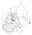
- FIG. 1 illustrates a dual-bearing reel 1 as a fishing reel according to an exemplary embodiment of the present invention.
- the dual-bearing reel 1 includes a reel unit 2, a spool 3 rotatably supported by the reel unit 2, and a handle assembly 4.
- the reel unit 2 includes a frame 5 and a cover member 6 for covering one side of the frame 5, i.e., the side to which the handle assembly 4 is attached.
- the handle assembly 4 is fixed onto a handle shaft 8 rotatably supported by the reel unit 2.
- the handle assembly 4 includes a handle arm 10, a handle knob 11, and a nut member 12. Further, the nut member 12 is provided with an anti-loosening member (to be described hereinafter) for preventing the nut member 12 from being loosened.
- the handle shaft 8 has a gear portion 15 serving as an anti-loosening engaging portion, a male threaded portion 16 and an engaging portion 17 for rotation prevention.
- the gear portion 15 has a plurality of teeth. As illustrated in FIG. 3 , the teeth have a tapered surface 15a formed by the tip portions thereof in a direction along the handle shaft 8 such that the outer diameter of the teeth is reduced towards the tip ends of the tip portions. In other words, the teeth become narrower as the tapered surface extends towards the tip. Moreover, as illustrated in FIGS. 3 and 4 , the teeth of the gear portion 15 are made in the form of ratchet teeth, and each has a structure that one tooth surface 15b is raised from the root circle of the gear portion 15 at a steeper angle than the other tooth surface 15c is. It should be noted that FIG. 4 is a view seen from a position away from the handle shaft 8 along the axial direction of the handle shaft 8, and some members such as the nut member 12 are not illustrated therein.
- the male threaded portion 16 and the engaging portion 17 for rotation prevention are formed in the same position in the handle axial direction.
- an elliptic cross-section is formed by the male threaded portion 16 and the engaging portion 17.
- the handle arm 10 is a plate member made of metal, and is extending from a first end portion 10a to a second end portion 10b in a direction perpendicular to the handle shaft 8.
- the handle arm 10 has an elongated hole 10c in the first end portion 10a.
- the elongated hole 10c is extending in the longitudinal direction of the handle arm 10.
- the engaging portion 17 of the handle shaft 8 is inserted in the elongated hole 10c. Therefore, the handle arm 10 is non-rotatable relatively to the handle shaft 8, and the position of the handle arm 10 fixed to the handle shaft 8 can be changed within a range that the elongated hole 10c is formed. In other words, the position of the handle arm 10 is adjustable in the elongated hole 10c.
- the handle knob 11 is rotatably supported by the second end portion 10b of the handle arm 10.
- the nut member 12 includes a body part 21 and a lever part 22 serving as switch operation mechanism.
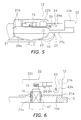
- FIG. 5 illustrates an opened position of the nut member 12 that the lever part 22 is opened from the body part 21
- FIG. 6 partially illustrates a closed position of the nut member 12 that the lever part 22 is closed to the body part 21.
- the nut member 12 enables the handle arm 10 to be fixed to the handle shaft 8 by screwing the body part 21 onto the male threaded portion 16 of the handle shaft 8.
- the body part 21 has a base portion 21a and a pair of sidewall portions 21b.
- the base portion 21a is formed in a roughly oval plate shape.
- the base portion 21a has a female threaded portion 21c in the center part thereof.
- the female threaded portion 21c is screwed onto the male threaded portion 16 of the handle shaft 8.
- the lever part 22 is disposed between the pair of sidewall portions 21b of the body part 21.
- the lever part 22 has a support portion 22a, a boss portion 22b, and a coupling portion 22c.
- the support portion 22a is formed in one longitudinal end of the lever part 22, whereas the boss portion 22b is formed in the other longitudinal end of the lever part 22.
- the coupling portion 22c couples the support portion 22a and the boss portion 22b.
- the support portion 22a is supported by the pair of sidewall portions 21b through a pin 23 so as to be openable and closable.
- the boss portion 22b is configured to make contact with the upper surface of the base portion 21a.
- the coupling portion 22c is a portion having a thickness smaller than that of the support portion 22a and that of the boss portion 22b.
- a stopper 24 serving as the anti-loosening member is mounted onto the back surface of the coupling portion 22, i.e., the surface opposed to the tip end of the handle shaft 8.
- the stopper 24 extends in an elongated shape along the lever part 22.
- the longitudinally center part of the stopper 24 is rotatably supported by the back surface of the lever part 22 through a pin 26.
- the stopper 24 has a pawl 24a formed on the tip end thereof.
- the pawl 24a is configured to be engaged with the tooth surface 15b (the aforementioned one tooth surface) of the gear portion 15.
- a flat spring 27 is mounted onto an end portion of the stopper 24 on the opposite side of the tip end that the pawl 24a is formed.
- the flat spring 27 urges the pawl 24a towards the gear portion 15.
- the flat spring 27 is supported by the back surface of the lever part 22.
- the nut member 12 and the gear portion 15 are allowed to rotate relatively to each other in an A direction (i.e., a direction of tightening the nut member 12) but are prevented from rotating relatively to each other in a B direction (i.e., a direction of loosening the nut member 12).
- the lever part 22 is provided with a maintaining mechanism 30 for maintaining the lever part 22 in the closed position.
- the maintaining mechanism 30 includes a pin 31, a recess 22d, and a coil spring 32.
- the pin 31 is slidably supported by a through hole configured in a first support portion 21c and that configured in a second support plate 33.
- the first support portion 21c is integrally formed with the upper surface of the base portion 21a of the nut member 12.
- the second support plate 33 is fixed to the upper surface of the base portion 21a.
- the recess 22d is formed on a lateral surface of the boss portion 22b of the lever part 22, i.e., a surface opposed to the first support portion 21c.
- the tip portion of the pin 31 is allowed to be engaged with the recess 22d.
- the coil spring 32 is disposed between the second support plate 33 and a brimmed portion 31a formed on the pin 31. The coil spring 32 urges the brimmed portion 31a (i.e., the pin 31) towards the recess 22d.
- the pin 31 can be protruding and retracted along the direction intersecting with the handle shaft 8, while being always urged towards the recess 22d by the coil spring 32. Further, the pin 31 can be moved in a direction away from the boss portion 22b against the urging force of the coil spring 32 by making contact with the lateral surface of the boss portion 22b.
- the lever part 22 of the nut member 12 is opened and is set in the opened position (see FIG. 5 ).
- the lever part 22 is set in the opened position, the pawl 24a of the stopper 24 on the back surface of the lever part 22 and the teeth of the gear portion 15 of the handle shaft 8 are disengaged from each other.
- the tip end (i.e., the boss portion 22b) of the lever part 22 is separated away from the handle shaft 8.
- the lever part 22 is herein changed into the form with a long arm length, and this makes it easy to perform a screw tightening operation or a screw loosening operation.
- the nut member 12 can be separated away from the handle arm 10 by rotating the nut member 12 in the screw loosening direction through the operation of the lever part 22.
- the handle arm 10 is unfixed from the handle shaft 8, and can be moved in the longitudinal direction thereof. Then, the handle shaft 8 is located in a desired position within the elongated hole 10c of the handle arm 10. Under the condition, the lever part 22 is held and rotated in the direction opposite from that in the aforementioned operation. Accordingly, the nut member 12 can be tightly screwed onto the male threaded portion 16 of the handle shaft 8. Through the tightening of the nut member 12, the handle arm 10 is fixed onto the handle shaft 8. Thereafter, the lever part 22 is set in the closed position.
- the teeth of the gear portion 15 are made in the form of ratchet teeth. Therefore, when the nut member 12 is rotated in the A direction depicted in FIG. 4 , the pawl 24a runs on the tooth surface 15c (i.e., the aforementioned other tooth surface), and simultaneously, the stopper 24 is rotated in a clockwise direction in the view in FIG. 4 about the pin 26 against the urging force of the flat spring 27. Thus, the nut member 12 can be rotated in the tightening direction.
- the lateral surface of the boss portion 22b makes contact with the tip end of the pin 31 of the maintaining mechanism 30.
- the pin 31 is retracted in the direction away from the boss portion 22b against the urging force of the coil spring 32.
- the tip end of the pin 31 is fitted into the recess 22d formed on the boss portion 22b. Therefore, the closed position of the lever part 22 is maintained.
- FIG. 8 illustrates a modification of the anti-loosening engaging portion of the handle shaft 8
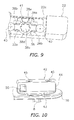
- FIG. 9 illustrates a modification of the anti-loosening member.
- the anti-loosening engaging portion of the handle shaft 8 is not made in the form of a gear portion having ratchet teeth but is made in the form of a spline shaft 36 having a plurality of teeth 35.
- each tooth 35 of the spline shaft 36 has a pair of tapered surfaces 35a on the tip portion thereof such that the tooth width thereof is reduced towards the tip end of the tip end portion.
- the anti-loosening member is made of a grooved plate 38.
- the grooved plate 38 extends along the longitudinal direction of the lever part 22, and is disposed in the inside of a groove 22e formed on the back surface of the coupling portion 22c.
- the grooved plate 38 has a disc portion 38a and a pair of leg portions 38b.
- the disc portion 38a is formed in the center part of the grooved plate 38.
- the leg portions 38b extends from the disc portion 38a in opposite directions along the longitudinal direction of the lever part 22.
- a circular hole 38c is configured in the disc portion 38a.
- the circular hole 38c has a plurality of grooves 38d formed on the inner peripheral edge thereof.
- the grooves 38d can be engaged with the respective teeth 35 of the spline shaft 36. Yet further, the tip portion of each leg portion 38b of the pair is rotatably supported, while a slight clearance is reliably produced between a head portion of a screw 40 and the groove 22e.
- each leg portion 38b of the grooved plate 38 is supported, while a clearance is reliably produced between the head portion of the screw 40 and the groove 22e.
- the grooved plate 38 can be rotated about the circular hole 38c within a predetermined angular range.
- a flat portion 38e is formed on a part of the outer periphery of the disc portion 38a of the grooved plate 38.
- a spring 41 which is formed in a trapezoidal shape in a plan view, makes contact with the flat portion 38e.
- the grooved plate 38 is maintained in a predetermined rotational position by the urging force of the spring 41.
- the teeth 35 of the spline shaft 36 are engaged with the grooves 38d of the grooved plate 38. Therefore, loosening of the nut member 12 can be prevented while the lever part 22 is closed. Further, when the teeth 35 make contact with a part of the grooved plate 38 in which the grooves 38d are not formed in setting the lever part 22 to the closed position, the grooved plate 38 is rotated against the urging force of the spring 41, and the teeth 35 of the spline shaft 36 are engaged with the grooves 38d of the grooved plate 38.
- FIGS. 10 and 11 illustrate yet another exemplary embodiment.
- the structure of the nut member in the present exemplary embodiment is different from the structures of the nut members in the aforementioned respective exemplary embodiment.
- the other structures in the present exemplary embodiment are similar to those in the aforementioned respective exemplary embodiments.
- FIG. 11 illustrates the interior of the nut member without illustrating a part of the nut member.
- a nut member 42 has a base portion 43 and a knob portion 44.
- the base portion 43 is formed in a roughly oval plate shape.
- the basic structure of the base portion 43 is the same as that of the aforementioned exemplary embodiment.
- a hole is configured in the center part of the base portion 43, and further, a female threaded portion is formed in the hole.
- the knob portion 44 is a box-shaped member opened to the base portion 43 side. The knob portion 44 can be attached to the base portion 43 by two screws 45.
- a stopper 47 is rotatably mounted to the inside of the knob portion 44, while being extending in a direction intersecting with the handle shaft 8.
- the stopper 47 and a plate spring 48 for urging a pawl 47a formed on the tip end of the stopper 47 towards the gear portion 15 are structured similarly to the corresponding ones of the aforementioned exemplary embodiment illustrated in FIG. 4 .
- a push button 50 (switch operation mechanism) for disengagement is mounted to one end of the knob portion 44.
- the push button 50 is disposed on a lateral surface of the knob portion 44, while being partially protruding therefrom.
- the push button 50 can be herein pushed in and out.
- a coil spring 51 is disposed in the inside of the knob portion 44 in order to urge the push button 50 to the outside.
- the push button 50 is always urged by the coil spring 51 so as to be protruding to the outside.
- the push button 50 is moved to the inside of the knob portion 44.
- the push button 50 has a protrusion 50a disposed in the inside of the knob portion 44.
- the protrusion 50a makes contact with the other end 47b of the stopper 47. Further, when the push button 50 is pushed, the stopper 47 is rotated and the pawl 47a disposed on the tip end of the stopper 47 is disengaged from the teeth of the gear portion 15.
- the push button 50 is firstly pushed in loosening the nut member 42 for the purposes of the length adjustment of the handle arm 10 and so forth. Accordingly, the stopper 47 is rotated and the pawl 47a is disengaged from the teeth of the gear portion 15. Under the condition, the nut member 42 is allowed to be rotated in the loosening direction. Therefore, the handle arm 10 can be unfixed from the handle shaft 8 by loosening the nut member 42, and the length of the handle arm 10 can be changed.
Landscapes
- Life Sciences & Earth Sciences (AREA)
- Environmental Sciences (AREA)
- Animal Husbandry (AREA)
- Biodiversity & Conservation Biology (AREA)
Abstract

Description
- This application claims priority to Japanese Patent Application No.
2013-94965 filed on April 30, 2013 - The present invention relates to a fishing reel.
- A fishing reel is provided with a handle assembly for winding a fishing line. The handle assembly includes a handle arm and a handle knob. The handle arm is fixed to the tip portion of a handle shaft. The handle knob is mounted to the tip portion of the handle arm. Further, a type of handle assembly has been also provided so far. This type of handle assembly is capable of changing the length of the handle arm.
- For example, a fishing reel, which is described in Japan Laid-open Patent Application Publication No.
JP-A-2004-135624 JP-Y-H03-10860 JP-A-2004-222559 - As described in the aforementioned Publications Nos.
JP-A-2004-135624 JP-Y-H03-10860 JP-A-2004-222559 - However, in the structure described in the Publication No.
JP-A-2004-135624 JP-Y-H03-10860 JP-A-2004-222559 JP-A-2004-222559 - It is an advantage of the present invention to change the length of a handle arm and prevent loosening of a screw member for fixing the handle arm onto a handle shaft in a fishing reel.
- A fishing reel includes a reel unit, a handle shaft, a handle arm, a handle knob, a nut, and an anti-loosening member. The handle shaft is rotatably supported by the reel unit. The handle shaft includes an anti-loosening engaging portion and a male threaded portion on a tip portion thereof. The handle arm extends from a first end portion thereof to a second end portion thereof in a direction intersecting with the handle shaft. The handle arm includes an elongated hole in the first end portion thereof. The elongated hole extends in the direction. The handle shaft is inserted in the elongated hole to be non-rotatably engaged with the handle arm. A position of the shaft in the elongated hole being adjustable. The handle knob is rotatably attached to the second end portion of the handle arm. The nut member includes a female threaded portion. The female thread portion is screwed onto the male threaded portion of the handle shaft. The anti-loosening member is configured on the nut member and is being selectively set in a first position and a second position. The anti-loosening member is engaged with the anti-loosening engaging portion in the first position to prevent the nut member from loosening. The anti-loosening member is disengaged from the anti-loosening engaging portion in the second position to allow the nut member to rotate in the loosening direction.
- In the fishing reel, the handle arm is fixed onto the tip portion of the handle shaft by means of the nut member. The handle arm has the elongated hole, and the length of the handle arm can be changed by changing the fixed position of the handle shaft within the elongated hole.
- Further, loosening of the nut member can be prevented by setting the anti-loosening member in the first position, while the handle arm is fixed onto the handle shaft. On the other hand, in changing the length of the handle arm, the nut member can be loosened by setting the anti-loosening member in the second position. Therefore, when the form of the nut member can be changed by a manual operation, for instance, tightening of the nut member can be easily performed by an angler, and loosening of the nut member can be prevented.
- A fishing reel according to a second aspect of the present invention relates to the fishing reel according to the first aspect. The fishing reel further includes a switch operation mechanism for performing an operation of switching the anti-loosening member between the first position and the second position.
- Here, the anti-loosening member can be switched between the first position and the second position by the switch operation means.
- A fishing reel according to a third aspect of the present invention relates to the fishing reel according to the first or second aspect. In the fishing reel, the nut member includes a body part and a lever part. The body part is a member in which the female threaded portion is formed. The lever part is attached to the body part and is movable away from the body part. The anti-loosening member is configured to the lever part and includes a pawl. The pawl is configured to be engaged with the anti-loosening engaging portion when the lever part is attached to the body part. The pawl is configured to be disengaged from the anti-loosening engaging portion when the lever part is moved away from the body part.
In the fishing reel, when the lever part of the nut member is moved away from the body part, the pawl of the anti-loosening member mounted to the lever part is configured to be disengaged from the anti-loosening engaging portion of the handle shaft. Therefore, under the condition, the nut member can be loosened, and thus, it is possible to change the fixed position of the handle shaft with respect to the handle arm. By contrast, when the lever part is attached to the body part, the pawl of the anti-loosening member mounted to the lever part is engaged with the anti-loosening engaging portion of the handle shaft. Accordingly, loosening of the nut member can be prevented. - Here, the loosening-directional rotation of the nut member can be allowed or prevented by opening or closing the lever part with respect to the body part.
- A fishing reel according to a fourth aspect of the present invention relates to the fishing reel according to the third aspect. The fishing reel further includes a pawl urging member. The pawl urging member is configured to urge the pawl towards the anti-loosening engaging portion.
- Here, the pawl is urged by the pawl urging member. Accordingly, the pawl can be stably engaged with the anti-loosening engaging portion.
- A fishing reel according to a fifth aspect of the present invention relates to the fishing reel according to the third or fourth aspect. In the fishing reel, the anti-loosening member is configured on a surface of the lever part in opposition to the handle shaft.
- Here, the anti-loosening member is configured on the surface of the lever part in opposition to the handle shaft, i.e., the back surface of the lever part. Therefore, the anti-loosening member is not exposed to the outside, while the lever part is closed to the body part. Therefore, it is possible to prevent such a trouble that the fishing line gets stuck with the anti-loosening member.
- A fishing reel according to a sixth aspect of the present invention relates to the fishing reel according to any of the third to fifth aspects. In the fishing reel, the lever part is elongated in one direction. One longitudinal end of the lever part is coupled to the body part. The lever part extends in the direction intersecting with the handle shaft when the lever part is moved away from the body part.
- Here, when the lever part is moved away from the body part, the lever part extends in the direction intersecting with the handle shaft. Therefore, the lever part is enabled to function as a lever in rotating the nut member. This makes it easy to perform a manual operation of the nut member.
- A fishing reel according to a seventh aspect of the present invention relates to the fishing reel according to any of the third to sixth aspects. The fishing reel further includes a maintaining mechanism for maintaining the lever part when the lever part is attached to the body part.
- Here, when the lever part is closed to the body part, the maintaining mechanism is configured to maintain the lever part when the lever part is attached to the body part. Therefore, the lever part can be prevented from being unintentionally opened in use.
- A fishing reel according to an eighth aspect of the present invention relates to the fishing reel according to the seventh aspect. In the fishing reel, the maintaining mechanism includes a pin, a recess and a pin urging member. The pin is configured to the body part. The pin is configured to be advanced and retracted along the direction intersecting with the handle shaft. The recess is formed on the lever part. A tip portion of the pin to be engaged with the recess when the lever part is attached to the body part. The pin urging member is configured to urge the pin onto the recess.
- Here, when the lever part is closed to the body part, the pin of the body part is configured to enter the recess of the lever part. This state is maintained by the pin urging member. Therefore, the lever part can be stably set when the lever part is attached to the body part with the simple structure.
- A fishing reel according to a ninth aspect of the present invention relates to the fishing reel according to any of the third to eighth aspects. In the fishing reel, the anti-loosening engaging portion includes a plurality of teeth formed on the tip portion of the handle shaft.
- Here, the pawl of the anti-loosening member mounted to the lever part is engaged with the plural teeth of the handle shaft. Thus, loosening of the nut member can be prevented.
- A fishing reel according to a tenth aspect of the present invention relates to the fishing reel according to the ninth aspect. In the fishing reel, each of the plurality of teeth include a tapered surface having tip portions. A diameter of the tapered surface becomes narrower as the tapered surface extends further towards the tip portions.
- Here, the tip portions of the plural teeth form a tapered surface. Therefore, when the lever part is closed to the body part, the pawl of the anti-loosening member mounted to the lever part can be easily engaged with the plural teeth.
- A fishing reel according to an eleventh aspect of the present invention relates to the fishing reel according to the ninth aspect. In the fishing reel, the anti-loosening member includes a stopper plate. The stopper plate is configured on the surface of the lever part in opposition to the handle shaft. The stopper plate includes a plurality of recesses to be meshed with the plurality of teeth.
- Here, the plural recesses of the stopper plate are engaged with the plural teeth of the handle shaft. Thus, loosening of the nut member can be prevented.
- A fishing reel according to a twelfth aspect of the present invention relates to the fishing reel according to the eleventh aspect. The fishing reel further includes a plate urging member. The plate urging member is configured to urge the stopper plate to a predetermined angular position. The stopper plate is supported by the lever part to be rotatable within a predetermined angular range.
- Here, the stopper plate is rotatable. Therefore, when the lever part is closed to the body part, the stopper plate is configured to be rotated against the urging force of the plate urging member if the recesses of the stopper plate and the plural teeth of the handle shaft cannot be meshed. Thus, the recesses and the teeth can be meshed, and thereby, the stopper plate and the handle shaft can be engaged.
- A fishing reel according to a thirteenth aspect of the present invention relates to the fishing reel according to the eleventh or twelfth aspect. In the fishing reel, each of the plurality of teeth includes a tapered surface having a tip portion. a width of each of the plurality of teeth becomes smaller as the tapered surface extends further to the tip portion.
- Here, each of the plural teeth has a tapered surface on the tip portion thereof. Therefore, when the lever part is closed to the body part, the recesses of the stopper plate can be easily engaged with the plural teeth.
- A fishing reel according to a fourteenth aspect of the present invention relates to the fishing reel according to the first or second aspect. In the fishing reel, the anti-loosening member includes a stopper, an urging member and an operating member. The stopper is rotatably configured to the nut member. The stopper is selectively set in a first position and a second position. The stopper is engaged with the anti-loosening engaging portion when the stopper is in the first position, and the stopper is disengaged from the anti-loosening engaging portion when the stopper is in the second position. The urging member is configured to urge the stopper towards the first position. The operating member is configured to set the stopper in the second position against an urging force of the urging member.
- Here, the stopper is engaged with the anti-loosening engaging portion, while being urged towards the first position by the urging member. Under the condition, the nut member is prevented from rotating in the loosening direction. By contrast, when the stopper is set in the second position by the operating member, the stopper is configured to be disengaged from the anti-loosening engaging portion.
- A fishing reel according to a fifteenth aspect of the present invention relates to the fishing reel according to the second aspect. In the fishing reel, the switch operation mechanism is the lever part.
- A fishing reel according to a sixteenth aspect of the present invention relates to the fishing reel according to the fourteenth aspect. In the fishing reel, the switch operation mechanism is the operating member.
- Referring now to the attached drawings which form a part of this original disclosure:
-
FIG. 1 is a perspective view of a dual-bearing reel according to an exemplary embodiment of the present invention: -
FIG. 2 is an exploded perspective view of a handle arm coupled part; -
FIG. 3 is an external view of a tip portion of a handle shaft; -
FIG. 4 is a schematic view of an anti-loosening mechanism; -
FIG. 5 is an external perspective view of a nut member in an opened state; -
FIG. 6 is a partial cross-sectional view for illustrating a relation between the nut number and the handle shaft; -
FIG. 7 is a partial side view of a maintaining mechanism; -
FIG. 8 is an external perspective view of an anti-loosening engaging portion of the handle shaft in another exemplary embodiment; -
FIG. 9 is a diagram corresponding toFIG. 5 according to another exemplary embodiment; -
FIG. 10 is an external perspective view of a nut member according to yet another exemplary embodiment; and -
FIG. 11 is a plan view of the nut member illustrated inFIG. 10 . -
FIG. 1 illustrates a dual-bearing reel 1 as a fishing reel according to an exemplary embodiment of the present invention. The dual-bearing reel 1 includes a reel unit 2, a spool 3 rotatably supported by the reel unit 2, and a handle assembly 4. The reel unit 2 includes aframe 5 and a cover member 6 for covering one side of theframe 5, i.e., the side to which the handle assembly 4 is attached. - The handle assembly 4 is fixed onto a
handle shaft 8 rotatably supported by the reel unit 2. The handle assembly 4 includes ahandle arm 10, ahandle knob 11, and anut member 12. Further, thenut member 12 is provided with an anti-loosening member (to be described hereinafter) for preventing thenut member 12 from being loosened. - As illustrated in
FIG. 2 , thehandle shaft 8 has agear portion 15 serving as an anti-loosening engaging portion, a male threadedportion 16 and an engagingportion 17 for rotation prevention. - The
gear portion 15 has a plurality of teeth. As illustrated inFIG. 3 , the teeth have a tapered surface 15a formed by the tip portions thereof in a direction along thehandle shaft 8 such that the outer diameter of the teeth is reduced towards the tip ends of the tip portions. In other words, the teeth become narrower as the tapered surface extends towards the tip. Moreover, as illustrated inFIGS. 3 and 4 , the teeth of thegear portion 15 are made in the form of ratchet teeth, and each has a structure that onetooth surface 15b is raised from the root circle of thegear portion 15 at a steeper angle than theother tooth surface 15c is. It should be noted thatFIG. 4 is a view seen from a position away from thehandle shaft 8 along the axial direction of thehandle shaft 8, and some members such as thenut member 12 are not illustrated therein. - As illustrated in
FIG. 2 , the male threadedportion 16 and the engagingportion 17 for rotation prevention are formed in the same position in the handle axial direction. In the handle axial direction, an elliptic cross-section is formed by the male threadedportion 16 and the engagingportion 17. - As illustrated in
FIGS. 1 and2 , thehandle arm 10 is a plate member made of metal, and is extending from afirst end portion 10a to asecond end portion 10b in a direction perpendicular to thehandle shaft 8. Thehandle arm 10 has an elongatedhole 10c in thefirst end portion 10a. Theelongated hole 10c is extending in the longitudinal direction of thehandle arm 10. The engagingportion 17 of thehandle shaft 8 is inserted in theelongated hole 10c. Therefore, thehandle arm 10 is non-rotatable relatively to thehandle shaft 8, and the position of thehandle arm 10 fixed to thehandle shaft 8 can be changed within a range that theelongated hole 10c is formed. In other words, the position of thehandle arm 10 is adjustable in theelongated hole 10c. Thehandle knob 11 is rotatably supported by thesecond end portion 10b of thehandle arm 10. - As illustrated in
FIGS. 5 and 6 , thenut member 12 includes abody part 21 and alever part 22 serving as switch operation mechanism. It should be noted thatFIG. 5 illustrates an opened position of thenut member 12 that thelever part 22 is opened from thebody part 21, whereasFIG. 6 partially illustrates a closed position of thenut member 12 that thelever part 22 is closed to thebody part 21. Thenut member 12 enables thehandle arm 10 to be fixed to thehandle shaft 8 by screwing thebody part 21 onto the male threadedportion 16 of thehandle shaft 8. - The
body part 21 has abase portion 21a and a pair ofsidewall portions 21b. Thebase portion 21a is formed in a roughly oval plate shape. Thebase portion 21a has a female threadedportion 21c in the center part thereof. The female threadedportion 21c is screwed onto the male threadedportion 16 of thehandle shaft 8. - The
lever part 22 is disposed between the pair ofsidewall portions 21b of thebody part 21. Thelever part 22 has asupport portion 22a, aboss portion 22b, and acoupling portion 22c. Thesupport portion 22a is formed in one longitudinal end of thelever part 22, whereas theboss portion 22b is formed in the other longitudinal end of thelever part 22. Thecoupling portion 22c couples thesupport portion 22a and theboss portion 22b. Thesupport portion 22a is supported by the pair ofsidewall portions 21b through apin 23 so as to be openable and closable. When thelever part 22 is set in the closed position, theboss portion 22b is configured to make contact with the upper surface of thebase portion 21a. Thecoupling portion 22c is a portion having a thickness smaller than that of thesupport portion 22a and that of theboss portion 22b. As illustrated inFIGS. 4 to 6 , astopper 24 serving as the anti-loosening member is mounted onto the back surface of thecoupling portion 22, i.e., the surface opposed to the tip end of thehandle shaft 8. - The
stopper 24 extends in an elongated shape along thelever part 22. The longitudinally center part of thestopper 24 is rotatably supported by the back surface of thelever part 22 through apin 26. Thestopper 24 has apawl 24a formed on the tip end thereof. Thepawl 24a is configured to be engaged with thetooth surface 15b (the aforementioned one tooth surface) of thegear portion 15. Aflat spring 27 is mounted onto an end portion of thestopper 24 on the opposite side of the tip end that thepawl 24a is formed. Theflat spring 27 urges thepawl 24a towards thegear portion 15. Theflat spring 27 is supported by the back surface of thelever part 22. - As illustrated in
FIG. 4 , when thepawl 24a is engaged with thetooth surface 15b (i.e., the aforementioned one tooth surface) of thegear portion 15, thenut member 12 and the gear portion 15 (i.e., the handle shaft 8) are allowed to rotate relatively to each other in an A direction (i.e., a direction of tightening the nut member 12) but are prevented from rotating relatively to each other in a B direction (i.e., a direction of loosening the nut member 12). - As illustrated in
FIG. 7 , thelever part 22 is provided with a maintainingmechanism 30 for maintaining thelever part 22 in the closed position. The maintainingmechanism 30 includes apin 31, arecess 22d, and acoil spring 32. Thepin 31 is slidably supported by a through hole configured in afirst support portion 21c and that configured in asecond support plate 33. Thefirst support portion 21c is integrally formed with the upper surface of thebase portion 21a of thenut member 12. Thesecond support plate 33 is fixed to the upper surface of thebase portion 21a. Therecess 22d is formed on a lateral surface of theboss portion 22b of thelever part 22, i.e., a surface opposed to thefirst support portion 21c. When thelever part 22 is set in the closed position, the tip portion of thepin 31 is allowed to be engaged with therecess 22d. Thecoil spring 32 is disposed between thesecond support plate 33 and abrimmed portion 31a formed on thepin 31. Thecoil spring 32 urges the brimmedportion 31a (i.e., the pin 31) towards therecess 22d. - With the structure as described above, the
pin 31 can be protruding and retracted along the direction intersecting with thehandle shaft 8, while being always urged towards therecess 22d by thecoil spring 32. Further, thepin 31 can be moved in a direction away from theboss portion 22b against the urging force of thecoil spring 32 by making contact with the lateral surface of theboss portion 22b. - In adjusting the handle length, the
lever part 22 of thenut member 12 is opened and is set in the opened position (seeFIG. 5 ). When thelever part 22 is set in the opened position, thepawl 24a of thestopper 24 on the back surface of thelever part 22 and the teeth of thegear portion 15 of thehandle shaft 8 are disengaged from each other. Further, under the condition that thelever part 22 is set in the opened position, the tip end (i.e., theboss portion 22b) of thelever part 22 is separated away from thehandle shaft 8. Thus, thelever part 22 is herein changed into the form with a long arm length, and this makes it easy to perform a screw tightening operation or a screw loosening operation. Next, thenut member 12 can be separated away from thehandle arm 10 by rotating thenut member 12 in the screw loosening direction through the operation of thelever part 22. - Through the aforementioned operation, the
handle arm 10 is unfixed from thehandle shaft 8, and can be moved in the longitudinal direction thereof. Then, thehandle shaft 8 is located in a desired position within theelongated hole 10c of thehandle arm 10. Under the condition, thelever part 22 is held and rotated in the direction opposite from that in the aforementioned operation. Accordingly, thenut member 12 can be tightly screwed onto the male threadedportion 16 of thehandle shaft 8. Through the tightening of thenut member 12, thehandle arm 10 is fixed onto thehandle shaft 8. Thereafter, thelever part 22 is set in the closed position. - When the opened position of the
lever part 22 is changed to the closed position, thepawl 24a of thestopper 24 disposed on the back surface of thelever part 22 is engaged with the teeth of thegear portion 15 of the handle shaft 8 (seeFIG. 4 ). Therefore, thenut member 12 can be prevented from rotating in the loosening direction with respect to thehandle shaft 8. - It should be noted that, when the
pawl 24a of thestopper 24 is engaged with the teeth of thegear portion 15, this engaging action can be smoothly done due to the tapered surface 15a formed on the tip portion of thegear portion 15. - Further, when the
nut member 12 is tightly screwed onto thehandle shaft 8, this tightening action can be done while the closed position of thelever part 22 is maintained. As illustrated inFIG. 4 and so forth, the teeth of thegear portion 15 are made in the form of ratchet teeth. Therefore, when thenut member 12 is rotated in the A direction depicted inFIG. 4 , thepawl 24a runs on thetooth surface 15c (i.e., the aforementioned other tooth surface), and simultaneously, thestopper 24 is rotated in a clockwise direction in the view inFIG. 4 about thepin 26 against the urging force of theflat spring 27. Thus, thenut member 12 can be rotated in the tightening direction. - When the opened position of the
lever part 22 is changed to the closed position, the lateral surface of theboss portion 22b makes contact with the tip end of thepin 31 of the maintainingmechanism 30. When thelever part 22 is further pressed into thebody part 21 towards thebase portion 21a under the condition, thepin 31 is retracted in the direction away from theboss portion 22b against the urging force of thecoil spring 32. When thelever part 22 is yet further pressed into thebody part 21, the tip end of thepin 31 is fitted into therecess 22d formed on theboss portion 22b. Therefore, the closed position of thelever part 22 is maintained. -
- (1) The
nut member 12 is provided with thestopper 24 as the anti-loosening member. Therefore, loosening of thenut member 12 can be reliably prevented even in manually tightening thenut member 12 with a small force. - (2) Rotation of the
nut member 12 in the loosening direction can be prevented/allowed by closing/opening thelever part 22 to/from thebody part 21. Further, when set in the opened position, thelever part 22 can be used as a lever for operating thenut member 12. Therefore, thenut member 12 can be easily operated. - (3) The
pawl 24a of thestopper 24 is always urged by theflat spring 27 so as to be engaged with the teeth of thegear portion 15. Therefore, thepawl 24a can be stably engaged with the teeth of thegear portion 15. - (4) The
stopper 24 is disposed on the back surface of thelever part 22. Therefore, thestopper 24 does not extend on the surface of thenut member 12, while thelever part 22 is closed. Accordingly, the fishing line can be prevented from getting stuck with thestopper 24. - (5) When the
lever part 22 is closed, the tip end of thepin 31 is fitted into therecess 22d of thelever part 22. Accordingly, the closed position of thelever part 22 is maintained. Therefore, thelever part 22 can be prevented from being unintentionally opened in use. - (6) The tapered surface 15a is formed by the tip portions of the teeth of the
gear portion 15. Therefore, when thelever part 22 is closed, thepawl 24a can be easily engaged with the plural teeth. - The present invention is not limited to the exemplary embodiment as described above, and a variety of changes or modifications can be herein made without departing from the scope of the present invention.
- (a)
FIG. 8 illustrates a modification of the anti-loosening engaging portion of thehandle shaft 8, whereasFIG. 9 illustrates a modification of the anti-loosening member. In the modification ofFIG. 8 , the anti-loosening engaging portion of thehandle shaft 8 is not made in the form of a gear portion having ratchet teeth but is made in the form of aspline shaft 36 having a plurality ofteeth 35. As illustrated in a partially enlarged view inFIG. 8 , eachtooth 35 of thespline shaft 36 has a pair of taperedsurfaces 35a on the tip portion thereof such that the tooth width thereof is reduced towards the tip end of the tip end portion. - Further, as illustrated in
FIG. 9 , the anti-loosening member is made of agrooved plate 38. Thegrooved plate 38 extends along the longitudinal direction of thelever part 22, and is disposed in the inside of agroove 22e formed on the back surface of thecoupling portion 22c. Thegrooved plate 38 has adisc portion 38a and a pair ofleg portions 38b. Thedisc portion 38a is formed in the center part of thegrooved plate 38. Theleg portions 38b extends from thedisc portion 38a in opposite directions along the longitudinal direction of thelever part 22. Further, acircular hole 38c is configured in thedisc portion 38a. Thecircular hole 38c has a plurality ofgrooves 38d formed on the inner peripheral edge thereof. Thegrooves 38d can be engaged with therespective teeth 35 of thespline shaft 36. Yet further, the tip portion of eachleg portion 38b of the pair is rotatably supported, while a slight clearance is reliably produced between a head portion of ascrew 40 and thegroove 22e. - A clearance is produced between each
leg portion 38b of thegrooved plate 38 and thegroove 22e of thecoupling portion 22c. Further, eachleg portion 38b of thegrooved plate 38 is supported, while a clearance is reliably produced between the head portion of thescrew 40 and thegroove 22e. With the structure, thegrooved plate 38 can be rotated about thecircular hole 38c within a predetermined angular range. - Further, a
flat portion 38e is formed on a part of the outer periphery of thedisc portion 38a of thegrooved plate 38. Aspring 41, which is formed in a trapezoidal shape in a plan view, makes contact with theflat portion 38e. Thegrooved plate 38 is maintained in a predetermined rotational position by the urging force of thespring 41. - In the present exemplary embodiment, when the opened position of the
lever part 22 is changed to the closed position, theteeth 35 of thespline shaft 36 are engaged with thegrooves 38d of thegrooved plate 38. Therefore, loosening of thenut member 12 can be prevented while thelever part 22 is closed. Further, when theteeth 35 make contact with a part of thegrooved plate 38 in which thegrooves 38d are not formed in setting thelever part 22 to the closed position, thegrooved plate 38 is rotated against the urging force of thespring 41, and theteeth 35 of thespline shaft 36 are engaged with thegrooves 38d of thegrooved plate 38. - Even the exemplary embodiment herein described can achieve advantageous effects similar to those achieved by the aforementioned exemplary embodiment.
- (b)
FIGS. 10 and11 illustrate yet another exemplary embodiment. The structure of the nut member in the present exemplary embodiment is different from the structures of the nut members in the aforementioned respective exemplary embodiment. However, the other structures in the present exemplary embodiment are similar to those in the aforementioned respective exemplary embodiments. It should be noted thatFIG. 11 illustrates the interior of the nut member without illustrating a part of the nut member. - A
nut member 42 has abase portion 43 and aknob portion 44. Similarly to the aforementioned exemplary embodiment, thebase portion 43 is formed in a roughly oval plate shape. The basic structure of thebase portion 43 is the same as that of the aforementioned exemplary embodiment. As illustrated inFIG. 6 , a hole is configured in the center part of thebase portion 43, and further, a female threaded portion is formed in the hole. Theknob portion 44 is a box-shaped member opened to thebase portion 43 side. Theknob portion 44 can be attached to thebase portion 43 by twoscrews 45. - A
stopper 47 is rotatably mounted to the inside of theknob portion 44, while being extending in a direction intersecting with thehandle shaft 8. Thestopper 47 and aplate spring 48 for urging apawl 47a formed on the tip end of thestopper 47 towards thegear portion 15 are structured similarly to the corresponding ones of the aforementioned exemplary embodiment illustrated inFIG. 4 . - A push button 50 (switch operation mechanism) for disengagement is mounted to one end of the
knob portion 44. Thepush button 50 is disposed on a lateral surface of theknob portion 44, while being partially protruding therefrom. Thepush button 50 can be herein pushed in and out. Further, acoil spring 51 is disposed in the inside of theknob portion 44 in order to urge thepush button 50 to the outside. Thus, thepush button 50 is always urged by thecoil spring 51 so as to be protruding to the outside. When pushed from the outside, thepush button 50 is moved to the inside of theknob portion 44. - The
push button 50 has aprotrusion 50a disposed in the inside of theknob portion 44. Theprotrusion 50a makes contact with theother end 47b of thestopper 47. Further, when thepush button 50 is pushed, thestopper 47 is rotated and thepawl 47a disposed on the tip end of thestopper 47 is disengaged from the teeth of thegear portion 15. - In the exemplary embodiment herein described, when the
knob portion 44 is held and rotated in the direction of tightening thenut member 42, thepawl 47a of thestopper 47 gets across the teeth of thegear portion 15 against the urging force of theplate spring 48, and rotation of thenut member 42 is allowed similarly to the aforementioned exemplary embodiment. In contrast, when thenut member 42 tries to rotate in the loosening direction, thepawl 47a of thestopper 47 is engaged with the teeth of thegear portion 15, and rotation of thenut member 42 is prevented. Therefore, loosening of thenut member 42 is prevented. - On the other hand, the
push button 50 is firstly pushed in loosening thenut member 42 for the purposes of the length adjustment of thehandle arm 10 and so forth. Accordingly, thestopper 47 is rotated and thepawl 47a is disengaged from the teeth of thegear portion 15. Under the condition, thenut member 42 is allowed to be rotated in the loosening direction. Therefore, thehandle arm 10 can be unfixed from thehandle shaft 8 by loosening thenut member 42, and the length of thehandle arm 10 can be changed. - In understanding the scope of the present invention, the term "comprising" and its derivatives, as used herein, are intended to be open ended terms that specify the presence of the stated features, elements, components, groups, integers, and/or steps, but do not exclude the presence of other unstated features, elements, components, groups, integers and/or steps. The foregoing also applies to words having similar meanings such as the terms, "including", "having" and their derivatives. Also, the terms "part," "section," "portion," "member" or "element" when used in the singular can have the dual meaning of a single part or a plurality of parts. Finally, terms of degree such as "substantially", "about" and "approximately" as used herein mean a reasonable amount of deviation of the modified term such that the end result is not significantly changed. For example, these terms can be construed as including a deviation of at least ± 5% of the modified term if this deviation would not negate the meaning of the word it modifies.
- While only selected embodiments have been chosen to illustrate the present invention, it will be apparent to those skilled in the art from this disclosure that various changes and modifications can be made herein without departing from the scope of the invention as defined in the appended claims. Furthermore, the foregoing descriptions of the embodiments according to the present invention are provided for illustration only, and not for the purpose of limiting the invention as defined by the appended claims and their equivalents.
Claims (16)
- A fishing reel (1), comprising:a reel unit (2);a handle shaft (8) being rotatably supported by the reel unit (2), the handle shaft including an anti-loosening engaging portion (15) and a male threaded portion (16) on a tip portion thereof;a handle arm (10) extending from a first end portion (10a) thereof to a second end portion (10b) thereof in a longitudinal direction intersecting with the handle shaft (8), the handle arm (10) including an elongated hole (10c) in the first end portion (10a) thereof, the elongated hole (10c) extending in the longitudinal direction, the handle shaft (8) being inserted in the elongated hole (10c) to be non-rotatably engaged with the handle arm (10), a position of the handle shaft (8) in the elongated hole (10c) being adjustable;a handle knob (11) being rotatably attached to the second end portion (10b) of the handle arm (10);a nut member (12, 42) including a female threaded portion (21c), the female thread portion being screwed onto the male threaded portion (16) of the handle shaft (8); andan anti-loosening member (24, 38, 47) being configured on the nut member (12, 42), the anti-loosening member being selectively set in a first position and a second position,the anti-loosening member (24, 38, 47) being engaged with the anti-loosening engaging portion (15) in the first position to prevent the nut member (12, 42) from loosening,the anti-loosening member (24, 38, 47) being disengaged from the anti-loosening engaging portion (15) in the second position to allow the nut member (12, 42) to rotate in the loosening direction.
- The fishing reel (1) according to claim 1, further comprising
a switch operation mechanism (22, 50) for performing an operation of switching the anti-loosening member (24, 38, 47) between the first position and the second position. - The fishing reel (1) according to claim 1 or 2, whereinthe nut member (12) includesa body part (21) in which the female threaded portion (21c) is formed, anda lever part (22) being attached to the body part (21) and being movable away from the body part (21),the anti-loosening member (24) is configured to the lever part (22) and includes a pawl (24a),the pawl (24a) is configured to be engaged with the anti-loosening engaging portion (15) when the lever part (22) is attached to the body part (21),the pawl (24a) is configured to be disengaged from the anti-loosening engaging portion (15) when the lever part (22) is moved away from the body part (21).
- The fishing reel (1) according to claim 3, further comprising
a pawl urging member (27) being configured to urge the pawl (24a) towards the anti-loosening engaging portion (15). - The fishing reel (1) according to claim 3 or 4, wherein
the anti-loosening member (24) is configured on a surface of the lever part (22) in opposition to the handle shaft (8). - The fishing reel (1) according to any of claims 3 to 5, wherein
the lever part (22) is elongated in one direction,
one longitudinal end (22a) of the lever part being coupled to the body part (21),
the lever part (22) extends in a direction intersecting with the handle shaft (8) when the lever part (22) is moved away from the body part (21). - The fishing reel (1) according to any of claims 3 to 6, further comprising
a maintaining mechanism (30) configured to maintain the lever part (22) when the lever is attached to the body part (21). - The fishing reel (1) according to claim 7, whereinthe maintaining mechanism (30) includesa pin (31) being configured to the body part (21), where the pin is configured to be advanced and retracted along the longitudinal direction intersecting with the handle shaft,a recess (22d) being formed on the lever part (22), where a tip portion of the pin (31) is engaged with the recess (22d) when the lever part (22) is attached to the body part (21), anda pin urging member (32) configured to urge the pin (31) towards the recess (22d).
- The fishing reel (1) according to any preceding claim, wherein
the anti-loosening engaging portion (15, 36) includes a plurality of teeth formed on the tip portion of the handle shaft (8). - The fishing reel (1) according to claim 9, wherein
each of the plurality of teeth include a tapered surface (15a, 35a) having a tip portion, and
a diameter of the tapered surface (15a, 35a) becomes narrower as the tapered surface extends further towards the tip portion. - The fishing reel (1) according to claim 9 when dependent on claim 1, wherein thenut member (12) includesa body part (21) in which the female threaded portion (21c) is formed, anda lever part (22) being attached to the body part (21) and being movable away from the body part (21),the anti-loosening member includes a stopper plate (38) being configured on the surface of the lever part (22) in opposition to the handle shaft (8), andthe stopper plate (38) includes a plurality of recesses (38d) to be meshed with the plurality of teeth (35).
- The fishing reel (1) according to claim 11, further comprising
a plate urging member (41) configured to urge the stopper plate (38) to a predetermined angular position, wherein
the stopper plate (38) is supported by the lever part (22) to be rotatable within a predetermined angular range. - The fishing reel (1) according to claim 11 or 12, wherein
each of the plurality of teeth (35) includes a tapered surface (35a) having a tip portion, and
a width of each of the plurality of teeth (35) becomes smaller as the tapered surface (35a) extends further to the tip portions. - The fishing reel (1) according to claim 1 or 2, whereinthe anti-loosening member includesa stopper (47) being rotatably configured to the nut member (42), where the stopper (47) is selectively set in the first position and the second position, the stopper (47) is engaged with the anti-loosening engaging portion (15) when the stopper (47) is in the first position, and the stopper (47) is disengaged from the anti-loosening engaging portion (15) when the stopper (47) is in the second position,an urging member (48) configured to urge the stopper (47) towards the first position, andan operating member (50) configured to set the stopper (47) in the second position against an urging force of the urging member (48).
- The fishing reel (1) according claim 2, wherein
the switch operation mechanism is the lever part (22). - The fishing reel (1) according to claim 14, wherein
the switch operation mechanism is the operating member (50).
Applications Claiming Priority (1)
| Application Number | Priority Date | Filing Date | Title |
|---|---|---|---|
| JP2013094965A JP6227891B2 (en) | 2013-04-30 | 2013-04-30 | Fishing reel |
Publications (2)
| Publication Number | Publication Date |
|---|---|
| EP2798952A1 true EP2798952A1 (en) | 2014-11-05 |
| EP2798952B1 EP2798952B1 (en) | 2018-06-06 |
Family
ID=50390015
Family Applications (1)
| Application Number | Title | Priority Date | Filing Date |
|---|---|---|---|
| EP14163094.7A Not-in-force EP2798952B1 (en) | 2013-04-30 | 2014-04-01 | Fishing reel |
Country Status (7)
| Country | Link |
|---|---|
| US (1) | US9295241B2 (en) |
| EP (1) | EP2798952B1 (en) |
| JP (1) | JP6227891B2 (en) |
| KR (1) | KR102232593B1 (en) |
| CN (1) | CN104126554B (en) |
| MY (1) | MY177694A (en) |
| TW (1) | TWI627901B (en) |
Families Citing this family (6)
| Publication number | Priority date | Publication date | Assignee | Title |
|---|---|---|---|---|
| KR101725961B1 (en) * | 2016-02-24 | 2017-04-12 | 유한책임회사 도요엔지니어링 | Fishing reel equipped with looseproof handle |
| JP7105613B2 (en) * | 2018-05-22 | 2022-07-25 | 株式会社シマノ | Handle return position adjustment mechanism for fishing reel |
| JP7086827B2 (en) * | 2018-12-14 | 2022-06-20 | 株式会社シマノ | Fishing reel cap |
| CN111820200B (en) * | 2020-07-13 | 2021-12-14 | 山东环球渔具股份有限公司 | Connecting structure of fishing line reel |
| JP7586697B2 (en) * | 2020-12-10 | 2024-11-19 | 株式会社シマノ | Electric reel |
| KR102460445B1 (en) * | 2021-12-03 | 2022-10-31 | 류원철 | Fishing reel handle |
Citations (6)
| Publication number | Priority date | Publication date | Assignee | Title |
|---|---|---|---|---|
| US2162173A (en) * | 1938-02-17 | 1939-06-13 | Jr Levin B Huntington | Adjustable crank structure |
| US2326023A (en) * | 1942-03-16 | 1943-08-03 | Cheney S Fredricksen | Adjustable handle |
| JPH0310860Y2 (en) | 1984-03-28 | 1991-03-18 | ||
| JP2003144022A (en) * | 2001-11-07 | 2003-05-20 | Daiwa Seiko Inc | Fishing reel |
| JP2004135624A (en) | 2002-10-21 | 2004-05-13 | Ever Green International:Kk | Fishing reel |
| JP2004222559A (en) | 2003-01-21 | 2004-08-12 | Ever Green International:Kk | Fishing reel handle device |
Family Cites Families (11)
| Publication number | Priority date | Publication date | Assignee | Title |
|---|---|---|---|---|
| JPS608693Y2 (en) * | 1979-12-27 | 1985-03-28 | リヨ−ビ株式会社 | Double bearing reel frame |
| US5489070A (en) * | 1985-07-22 | 1996-02-06 | Zebco Corporation | Bait casting fishing reel |
| JP2922572B2 (en) * | 1990-04-06 | 1999-07-26 | 株式会社シマノ | Transmission for fishing reel |
| JP3325773B2 (en) * | 1996-05-16 | 2002-09-17 | 株式会社シマノ | Dual bearing reel braking system |
| JP3325779B2 (en) * | 1996-08-28 | 2002-09-17 | 株式会社シマノ | Dual bearing reel handle mounting structure |
| US6029922A (en) * | 1998-12-08 | 2000-02-29 | Brunswick Corporation | Retainer element for a securing element used to maintain a crank handle on a fishing reel |
| US6666396B2 (en) * | 2001-06-11 | 2003-12-23 | Gator Grip, Inc. | Multidirectional rotatable handle |
| JP4045167B2 (en) * | 2002-05-01 | 2008-02-13 | 株式会社シマノ | Spinning reel handle assembly |
| JP2006217848A (en) * | 2005-02-09 | 2006-08-24 | Shimano Inc | Handle assembly for spinning reel |
| JP2010273629A (en) * | 2009-05-29 | 2010-12-09 | Shimano Components Malaysia Sdn Bhd | Fishing reel handle assembly |
| JP2014050327A (en) * | 2012-09-05 | 2014-03-20 | Shimano Inc | Fishing reel |
-
2013
- 2013-04-30 JP JP2013094965A patent/JP6227891B2/en active Active
-
2014
- 2014-04-01 US US14/242,050 patent/US9295241B2/en active Active
- 2014-04-01 EP EP14163094.7A patent/EP2798952B1/en not_active Not-in-force
- 2014-04-10 TW TW103113230A patent/TWI627901B/en not_active IP Right Cessation
- 2014-04-16 MY MYPI2014700929A patent/MY177694A/en unknown
- 2014-04-18 KR KR1020140046647A patent/KR102232593B1/en not_active Expired - Fee Related
- 2014-04-30 CN CN201410179738.9A patent/CN104126554B/en not_active Expired - Fee Related
Patent Citations (6)
| Publication number | Priority date | Publication date | Assignee | Title |
|---|---|---|---|---|
| US2162173A (en) * | 1938-02-17 | 1939-06-13 | Jr Levin B Huntington | Adjustable crank structure |
| US2326023A (en) * | 1942-03-16 | 1943-08-03 | Cheney S Fredricksen | Adjustable handle |
| JPH0310860Y2 (en) | 1984-03-28 | 1991-03-18 | ||
| JP2003144022A (en) * | 2001-11-07 | 2003-05-20 | Daiwa Seiko Inc | Fishing reel |
| JP2004135624A (en) | 2002-10-21 | 2004-05-13 | Ever Green International:Kk | Fishing reel |
| JP2004222559A (en) | 2003-01-21 | 2004-08-12 | Ever Green International:Kk | Fishing reel handle device |
Also Published As
| Publication number | Publication date |
|---|---|
| CN104126554B (en) | 2018-09-18 |
| JP6227891B2 (en) | 2017-11-08 |
| US9295241B2 (en) | 2016-03-29 |
| KR20140130026A (en) | 2014-11-07 |
| US20140319264A1 (en) | 2014-10-30 |
| JP2014212770A (en) | 2014-11-17 |
| MY177694A (en) | 2020-09-23 |
| KR102232593B1 (en) | 2021-03-25 |
| CN104126554A (en) | 2014-11-05 |
| EP2798952B1 (en) | 2018-06-06 |
| TWI627901B (en) | 2018-07-01 |
| TW201507615A (en) | 2015-03-01 |
Similar Documents
| Publication | Publication Date | Title |
|---|---|---|
| US9295241B2 (en) | Fishing reel | |
| CN103070146B (en) | The torque limiting design of fishing reel | |
| US8657222B2 (en) | Drag mechanism for dual-bearing reel | |
| US9642349B2 (en) | Fishing reel | |
| US9591838B2 (en) | Clutch operating member of a dual-bearing reel | |
| KR101942879B1 (en) | Handle assembly for dual-bearing reel and dual-bearing reel | |
| US8534584B2 (en) | Dual-bearing reel speed change operation mechanism | |
| KR102002854B1 (en) | Handle assembly for spinning reel | |
| JP2014212770A5 (en) | ||
| KR102278088B1 (en) | Dual-bearing reel | |
| US6915974B2 (en) | Level wind mechanism for a dual bearing reel | |
| JP2013070651A5 (en) | ||
| JP5805516B2 (en) | Double bearing reel | |
| JP2013106543A5 (en) | ||
| US20070007377A1 (en) | Fishing reel | |
| US9848589B2 (en) | Knob of fishing reel and method of fabricating the same | |
| JP2013128439A5 (en) | ||
| JP6219702B2 (en) | Fishing reel drive gear and fishing reel pinion gear | |
| JP2015112099A5 (en) | ||
| JP3776029B2 (en) | Fishing reel | |
| JP5270507B2 (en) | Handle handle for fishing reel | |
| JP6261254B2 (en) | Torque Wrench | |
| JP2018110566A (en) | Double-bearing reel | |
| JP2005261207A (en) | Left and right-winding direction-switching mechanism of single axial bearing reel |
Legal Events
| Date | Code | Title | Description |
|---|---|---|---|
| PUAI | Public reference made under article 153(3) epc to a published international application that has entered the european phase |
Free format text: ORIGINAL CODE: 0009012 |
|
| 17P | Request for examination filed |
Effective date: 20140401 |
|
| AK | Designated contracting states |
Kind code of ref document: A1 Designated state(s): AL AT BE BG CH CY CZ DE DK EE ES FI FR GB GR HR HU IE IS IT LI LT LU LV MC MK MT NL NO PL PT RO RS SE SI SK SM TR |
|
| AX | Request for extension of the european patent |
Extension state: BA ME |
|
| R17P | Request for examination filed (corrected) |
Effective date: 20150410 |
|
| RBV | Designated contracting states (corrected) |
Designated state(s): AL AT BE BG CH CY CZ DE DK EE ES FI FR GB GR HR HU IE IS IT LI LT LU LV MC MK MT NL NO PL PT RO RS SE SI SK SM TR |
|
| STAA | Information on the status of an ep patent application or granted ep patent |
Free format text: STATUS: EXAMINATION IS IN PROGRESS |
|
| 17Q | First examination report despatched |
Effective date: 20161209 |
|
| GRAP | Despatch of communication of intention to grant a patent |
Free format text: ORIGINAL CODE: EPIDOSNIGR1 |
|
| STAA | Information on the status of an ep patent application or granted ep patent |
Free format text: STATUS: GRANT OF PATENT IS INTENDED |
|
| INTG | Intention to grant announced |
Effective date: 20171122 |
|
| GRAS | Grant fee paid |
Free format text: ORIGINAL CODE: EPIDOSNIGR3 |
|
| GRAA | (expected) grant |
Free format text: ORIGINAL CODE: 0009210 |
|
| STAA | Information on the status of an ep patent application or granted ep patent |
Free format text: STATUS: THE PATENT HAS BEEN GRANTED |
|
| AK | Designated contracting states |
Kind code of ref document: B1 Designated state(s): AL AT BE BG CH CY CZ DE DK EE ES FI FR GB GR HR HU IE IS IT LI LT LU LV MC MK MT NL NO PL PT RO RS SE SI SK SM TR |
|
| REG | Reference to a national code |
Ref country code: GB Ref legal event code: FG4D |
|
| REG | Reference to a national code |
Ref country code: CH Ref legal event code: EP Ref country code: AT Ref legal event code: REF Ref document number: 1005034 Country of ref document: AT Kind code of ref document: T Effective date: 20180615 |
|
| REG | Reference to a national code |
Ref country code: IE Ref legal event code: FG4D |
|
| REG | Reference to a national code |
Ref country code: DE Ref legal event code: R096 Ref document number: 602014026545 Country of ref document: DE |
|
| REG | Reference to a national code |
Ref country code: NL Ref legal event code: MP Effective date: 20180606 |
|
| REG | Reference to a national code |
Ref country code: LT Ref legal event code: MG4D |
|
| PG25 | Lapsed in a contracting state [announced via postgrant information from national office to epo] |
Ref country code: LT Free format text: LAPSE BECAUSE OF FAILURE TO SUBMIT A TRANSLATION OF THE DESCRIPTION OR TO PAY THE FEE WITHIN THE PRESCRIBED TIME-LIMIT Effective date: 20180606 Ref country code: ES Free format text: LAPSE BECAUSE OF FAILURE TO SUBMIT A TRANSLATION OF THE DESCRIPTION OR TO PAY THE FEE WITHIN THE PRESCRIBED TIME-LIMIT Effective date: 20180606 Ref country code: CY Free format text: LAPSE BECAUSE OF FAILURE TO SUBMIT A TRANSLATION OF THE DESCRIPTION OR TO PAY THE FEE WITHIN THE PRESCRIBED TIME-LIMIT Effective date: 20180606 Ref country code: BG Free format text: LAPSE BECAUSE OF FAILURE TO SUBMIT A TRANSLATION OF THE DESCRIPTION OR TO PAY THE FEE WITHIN THE PRESCRIBED TIME-LIMIT Effective date: 20180906 Ref country code: FI Free format text: LAPSE BECAUSE OF FAILURE TO SUBMIT A TRANSLATION OF THE DESCRIPTION OR TO PAY THE FEE WITHIN THE PRESCRIBED TIME-LIMIT Effective date: 20180606 Ref country code: NO Free format text: LAPSE BECAUSE OF FAILURE TO SUBMIT A TRANSLATION OF THE DESCRIPTION OR TO PAY THE FEE WITHIN THE PRESCRIBED TIME-LIMIT Effective date: 20180906 Ref country code: SE Free format text: LAPSE BECAUSE OF FAILURE TO SUBMIT A TRANSLATION OF THE DESCRIPTION OR TO PAY THE FEE WITHIN THE PRESCRIBED TIME-LIMIT Effective date: 20180606 |
|
| PG25 | Lapsed in a contracting state [announced via postgrant information from national office to epo] |
Ref country code: GR Free format text: LAPSE BECAUSE OF FAILURE TO SUBMIT A TRANSLATION OF THE DESCRIPTION OR TO PAY THE FEE WITHIN THE PRESCRIBED TIME-LIMIT Effective date: 20180907 Ref country code: LV Free format text: LAPSE BECAUSE OF FAILURE TO SUBMIT A TRANSLATION OF THE DESCRIPTION OR TO PAY THE FEE WITHIN THE PRESCRIBED TIME-LIMIT Effective date: 20180606 Ref country code: RS Free format text: LAPSE BECAUSE OF FAILURE TO SUBMIT A TRANSLATION OF THE DESCRIPTION OR TO PAY THE FEE WITHIN THE PRESCRIBED TIME-LIMIT Effective date: 20180606 Ref country code: HR Free format text: LAPSE BECAUSE OF FAILURE TO SUBMIT A TRANSLATION OF THE DESCRIPTION OR TO PAY THE FEE WITHIN THE PRESCRIBED TIME-LIMIT Effective date: 20180606 |
|
| REG | Reference to a national code |
Ref country code: AT Ref legal event code: MK05 Ref document number: 1005034 Country of ref document: AT Kind code of ref document: T Effective date: 20180606 |
|
| PG25 | Lapsed in a contracting state [announced via postgrant information from national office to epo] |
Ref country code: NL Free format text: LAPSE BECAUSE OF FAILURE TO SUBMIT A TRANSLATION OF THE DESCRIPTION OR TO PAY THE FEE WITHIN THE PRESCRIBED TIME-LIMIT Effective date: 20180606 |
|
| PG25 | Lapsed in a contracting state [announced via postgrant information from national office to epo] |
Ref country code: CZ Free format text: LAPSE BECAUSE OF FAILURE TO SUBMIT A TRANSLATION OF THE DESCRIPTION OR TO PAY THE FEE WITHIN THE PRESCRIBED TIME-LIMIT Effective date: 20180606 Ref country code: PL Free format text: LAPSE BECAUSE OF FAILURE TO SUBMIT A TRANSLATION OF THE DESCRIPTION OR TO PAY THE FEE WITHIN THE PRESCRIBED TIME-LIMIT Effective date: 20180606 Ref country code: SK Free format text: LAPSE BECAUSE OF FAILURE TO SUBMIT A TRANSLATION OF THE DESCRIPTION OR TO PAY THE FEE WITHIN THE PRESCRIBED TIME-LIMIT Effective date: 20180606 Ref country code: RO Free format text: LAPSE BECAUSE OF FAILURE TO SUBMIT A TRANSLATION OF THE DESCRIPTION OR TO PAY THE FEE WITHIN THE PRESCRIBED TIME-LIMIT Effective date: 20180606 Ref country code: AT Free format text: LAPSE BECAUSE OF FAILURE TO SUBMIT A TRANSLATION OF THE DESCRIPTION OR TO PAY THE FEE WITHIN THE PRESCRIBED TIME-LIMIT Effective date: 20180606 Ref country code: EE Free format text: LAPSE BECAUSE OF FAILURE TO SUBMIT A TRANSLATION OF THE DESCRIPTION OR TO PAY THE FEE WITHIN THE PRESCRIBED TIME-LIMIT Effective date: 20180606 Ref country code: IS Free format text: LAPSE BECAUSE OF FAILURE TO SUBMIT A TRANSLATION OF THE DESCRIPTION OR TO PAY THE FEE WITHIN THE PRESCRIBED TIME-LIMIT Effective date: 20181006 |
|
| PG25 | Lapsed in a contracting state [announced via postgrant information from national office to epo] |
Ref country code: SM Free format text: LAPSE BECAUSE OF FAILURE TO SUBMIT A TRANSLATION OF THE DESCRIPTION OR TO PAY THE FEE WITHIN THE PRESCRIBED TIME-LIMIT Effective date: 20180606 Ref country code: IT Free format text: LAPSE BECAUSE OF FAILURE TO SUBMIT A TRANSLATION OF THE DESCRIPTION OR TO PAY THE FEE WITHIN THE PRESCRIBED TIME-LIMIT Effective date: 20180606 |
|
| REG | Reference to a national code |
Ref country code: DE Ref legal event code: R097 Ref document number: 602014026545 Country of ref document: DE |
|
| PLBE | No opposition filed within time limit |
Free format text: ORIGINAL CODE: 0009261 |
|
| STAA | Information on the status of an ep patent application or granted ep patent |
Free format text: STATUS: NO OPPOSITION FILED WITHIN TIME LIMIT |
|
| 26N | No opposition filed |
Effective date: 20190307 |
|
| PG25 | Lapsed in a contracting state [announced via postgrant information from national office to epo] |
Ref country code: SI Free format text: LAPSE BECAUSE OF FAILURE TO SUBMIT A TRANSLATION OF THE DESCRIPTION OR TO PAY THE FEE WITHIN THE PRESCRIBED TIME-LIMIT Effective date: 20180606 Ref country code: DK Free format text: LAPSE BECAUSE OF FAILURE TO SUBMIT A TRANSLATION OF THE DESCRIPTION OR TO PAY THE FEE WITHIN THE PRESCRIBED TIME-LIMIT Effective date: 20180606 |
|
| PG25 | Lapsed in a contracting state [announced via postgrant information from national office to epo] |
Ref country code: AL Free format text: LAPSE BECAUSE OF FAILURE TO SUBMIT A TRANSLATION OF THE DESCRIPTION OR TO PAY THE FEE WITHIN THE PRESCRIBED TIME-LIMIT Effective date: 20180606 |
|
| REG | Reference to a national code |
Ref country code: CH Ref legal event code: PL |
|
| REG | Reference to a national code |
Ref country code: BE Ref legal event code: MM Effective date: 20190430 |
|
| PG25 | Lapsed in a contracting state [announced via postgrant information from national office to epo] |
Ref country code: MC Free format text: LAPSE BECAUSE OF FAILURE TO SUBMIT A TRANSLATION OF THE DESCRIPTION OR TO PAY THE FEE WITHIN THE PRESCRIBED TIME-LIMIT Effective date: 20180606 Ref country code: LU Free format text: LAPSE BECAUSE OF NON-PAYMENT OF DUE FEES Effective date: 20190401 |
|
| PG25 | Lapsed in a contracting state [announced via postgrant information from national office to epo] |
Ref country code: CH Free format text: LAPSE BECAUSE OF NON-PAYMENT OF DUE FEES Effective date: 20190430 Ref country code: LI Free format text: LAPSE BECAUSE OF NON-PAYMENT OF DUE FEES Effective date: 20190430 |
|
| PG25 | Lapsed in a contracting state [announced via postgrant information from national office to epo] |
Ref country code: BE Free format text: LAPSE BECAUSE OF NON-PAYMENT OF DUE FEES Effective date: 20190430 |
|
| PG25 | Lapsed in a contracting state [announced via postgrant information from national office to epo] |
Ref country code: TR Free format text: LAPSE BECAUSE OF FAILURE TO SUBMIT A TRANSLATION OF THE DESCRIPTION OR TO PAY THE FEE WITHIN THE PRESCRIBED TIME-LIMIT Effective date: 20180606 |
|
| PG25 | Lapsed in a contracting state [announced via postgrant information from national office to epo] |
Ref country code: IE Free format text: LAPSE BECAUSE OF NON-PAYMENT OF DUE FEES Effective date: 20190401 |
|
| PG25 | Lapsed in a contracting state [announced via postgrant information from national office to epo] |
Ref country code: PT Free format text: LAPSE BECAUSE OF FAILURE TO SUBMIT A TRANSLATION OF THE DESCRIPTION OR TO PAY THE FEE WITHIN THE PRESCRIBED TIME-LIMIT Effective date: 20181008 |
|
| PGFP | Annual fee paid to national office [announced via postgrant information from national office to epo] |
Ref country code: FR Payment date: 20210310 Year of fee payment: 8 |
|
| PGFP | Annual fee paid to national office [announced via postgrant information from national office to epo] |
Ref country code: GB Payment date: 20210318 Year of fee payment: 8 |
|
| PG25 | Lapsed in a contracting state [announced via postgrant information from national office to epo] |
Ref country code: MT Free format text: LAPSE BECAUSE OF FAILURE TO SUBMIT A TRANSLATION OF THE DESCRIPTION OR TO PAY THE FEE WITHIN THE PRESCRIBED TIME-LIMIT Effective date: 20180606 Ref country code: HU Free format text: LAPSE BECAUSE OF FAILURE TO SUBMIT A TRANSLATION OF THE DESCRIPTION OR TO PAY THE FEE WITHIN THE PRESCRIBED TIME-LIMIT; INVALID AB INITIO Effective date: 20140401 |
|
| PG25 | Lapsed in a contracting state [announced via postgrant information from national office to epo] |
Ref country code: MK Free format text: LAPSE BECAUSE OF FAILURE TO SUBMIT A TRANSLATION OF THE DESCRIPTION OR TO PAY THE FEE WITHIN THE PRESCRIBED TIME-LIMIT Effective date: 20180606 |
|
| GBPC | Gb: european patent ceased through non-payment of renewal fee |
Effective date: 20220401 |
|
| PG25 | Lapsed in a contracting state [announced via postgrant information from national office to epo] |
Ref country code: GB Free format text: LAPSE BECAUSE OF NON-PAYMENT OF DUE FEES Effective date: 20220401 Ref country code: FR Free format text: LAPSE BECAUSE OF NON-PAYMENT OF DUE FEES Effective date: 20220430 |
|
| P01 | Opt-out of the competence of the unified patent court (upc) registered |
Effective date: 20230428 |
|
| P02 | Opt-out of the competence of the unified patent court (upc) changed |
Effective date: 20230519 |
|
| PGFP | Annual fee paid to national office [announced via postgrant information from national office to epo] |
Ref country code: DE Payment date: 20240227 Year of fee payment: 11 |
|
| REG | Reference to a national code |
Ref country code: DE Ref legal event code: R119 Ref document number: 602014026545 Country of ref document: DE |
|
| PG25 | Lapsed in a contracting state [announced via postgrant information from national office to epo] |
Ref country code: DE Free format text: LAPSE BECAUSE OF NON-PAYMENT OF DUE FEES Effective date: 20251104 |