EP2798940A2 - Reel finger - Google Patents
Reel finger Download PDFInfo
- Publication number
- EP2798940A2 EP2798940A2 EP14160873.7A EP14160873A EP2798940A2 EP 2798940 A2 EP2798940 A2 EP 2798940A2 EP 14160873 A EP14160873 A EP 14160873A EP 2798940 A2 EP2798940 A2 EP 2798940A2
- Authority
- EP
- European Patent Office
- Prior art keywords
- finger
- flange
- rear flange
- front flange
- struts
- Prior art date
- Legal status (The legal status is an assumption and is not a legal conclusion. Google has not performed a legal analysis and makes no representation as to the accuracy of the status listed.)
- Granted
Links
Images




Classifications
-
- A—HUMAN NECESSITIES
- A01—AGRICULTURE; FORESTRY; ANIMAL HUSBANDRY; HUNTING; TRAPPING; FISHING
- A01D—HARVESTING; MOWING
- A01D57/00—Delivering mechanisms for harvesters or mowers
- A01D57/01—Devices for leading crops to the mowing apparatus
- A01D57/02—Devices for leading crops to the mowing apparatus using reels
Definitions
- This invention relates to agricultural harvesting heads. More particularly it relates to reels for agricultural harvesting heads. Even more particularly, it relates to fingers disposed on the reel to engage the tops of crop plants that are harvested by the agricultural harvesting head.
- Agricultural harvesting heads use reels that extend forward from the agricultural harvesting head.
- the reels extend laterally, generally parallel to the longitudinal extent of the agricultural harvesting head.
- the reels are provided to engage the tops of crop plants as they approach a reciprocating knife that also extends across the entire width of the agricultural harvesting head.
- a reciprocating knife severs the crop plants near their roots, elongate fingers on the reel engage the top of the crop plants, and direct the crop plants rearward so they fall upon the agricultural harvesting head rather than falling onto the ground.
- a finger for an agricultural harvesting head is formed as an I-beam.
- the I-beam is defined by a forward flange and a rear flange that are coupled together with a web, wherein the web is strengthened by laterally extending struts.
- a plurality of the fingers are supported on a bat.
- a plurality of the bats are supported on bat supports to rotate about a longitudinal rotational axis.
- the bat supports are supported on a central tube.
- the central tube is reported for rotation about the longitudinal rotational axis on a left end supporting arm and a right end supporting are disposed at either end of the central tube.
- a finger that is elongate and has a longitudinal extent, is provided for a reel of an agricultural harvesting head, the reel having a plurality of bats disposed about a longitudinal rotational axis, wherein each of the plurality of bats is configured to support a plurality of the fingers that are spaced apart and mounted side-by-side on each of the plurality of bats, the finger comprising a front flange that extends in a longitudinal and a transverse direction, a rear flange that extends in the longitudinal and the transverse direction and is spaced apart from the front flange, a web that extends between the front flange and the rear flange and is integrally formed with the front flange and the rear flange, and struts that are formed integral with the web and with the rear flange and that extend in a transverse direction.
- Adjacent struts may form a triangular box with the front flange.
- Adjacent struts may form a triangular box with the rear flange.
- Adjacent struts may form a rectangular box with the front flange and the rear flange.
- Adjacent struts may be generally parallel to each other and maybe perpendicular to the front flange and the rear flange.
- the struts may extend in a lateral direction a greater distance adjacent to the rear flange than adjacent to the front flange.
- Each pair of adjacent struts may meet at an acute angle at the front flange.
- Each pair of adjacent struts may meet at an acute angle at the rear flange.
- Each strut may be disposed at an acute angle with respect to the front flange, and maybe disposed at an acute angle with respect to the rear flange.
- a thickness of the web in a transverse direction may be less than a thickness of the front flange in a fore-and-aft direction.
- a thickness of the web in a transverse direction may be less than a thickness of the rear flange in a fore-and-aft direction.
- An extent of the front flange and an extent of the rear flange in a transverse direction may be at least three times an extent of the web in the transverse direction.
- An extent of the front flange and an extent of the rear flange in a transverse direction may be at least four times an extent of the web in the transverse direction.
- the terms “front”, “forward”, “in front of” and the like refer to the direction of travel of the real fingers engage the crop. This direction is indicated in the Figures by the directional arrow marked “V".
- the direction “V” is generally perpendicular to the longitudinal extent of the finger, and perpendicular to the longitudinal extent of the bat on which the finger is designed to be mounted.
- the terms “lateral”, “transverse”, “side-to-side” and the like refer to a direction parallel to the longitudinal extent of the bats on which the is designed to be mounted.
- the terms “up”, “upper”, “higher” and the like refer to a direction towards the bat on which the finger is designed to be mounted.
- the terms “down”, “downward”, “lower”, and the like refer to a direction away from the bat on which the finger is designed to be mounted.
- the reel assembly 100 includes a reel 102 that is elongate, to which a left end supporting arm 104, and a right end supporting arm 106 are attached.
- the reel 102 is comprised of a central tube 108 that is elongate to which six bat supports 110 are attached. Each bat support 110 is spaced evenly apart from its adjacent bat support 110 along the length of the central tube 108. Each bat support 110 has six bat mounts 112.
- Each of the bat mounts 112 on the bat support 110 supports six bats 114.
- Each bat mount 112 supports six bats 114 that are equiangularly spaced about the circumference of the central tube 108, and are equidistant from the longitudinal rotational axis 116 of the central tube 108.
- Fingers 118 are fixed to each of the six bats 114.
- Each finger 118 on a bat 114 is spaced equidistantly from its adjacent fingers 118.
- the fingers 118 are distributed along substantially the entire length of each bat 114.
- Finger 118 is an elongate member that has an upper end 200 that is configured to be fixed to bat 114, and a lower end 202 that is configured to engage the upper portions of crop plants. Finger 118 tapers inwardly in a downward direction over substantially its entire length. Tapering occurs in a transverse direction, as well as a fore and aft direction.
- Figure 118 has an upper portion 204 that is in the form of an I-beam that extends in a direction parallel to the longitudinal extent of the finger 118.
- Finger 118 has a lower portion 206 that is solid in cross section.
- the upper end 200 includes a strap 208 that extends about the bat 114, and is secured to itself with a fastener 210.
- Fastener 210 is a screw, bolt, or other threaded fastener. It may be a rivet or other flanged fastener made for permanent or semi-permanent attachment.
- the upper portion 204 of finger 118 comprises a front flange 212 that extends laterally and longitudinally.
- the upper portion 204 of finger 118 comprises a rear flange 214 that extends laterally and longitudinally.
- the upper portion 204 of finger 118 comprises a web 216 that extends in a fore and aft direction and is integrally formed with the front flange 212 and the rear flange 214.
- the front flange 212, the rear flange 214, and the web 216 form the I-beam structure.
- the thickness of the web 216 in a transverse direction is less than the thickness of the front flange 212 in a fore-and-aft direction, and is less than the thickness of the rear flange 214 in a fore-and-aft direction.
- the extent of the front flange 212 and the extent of the rear flange 214 in the transverse direction are three times greater than the extent of the web 216 in the transverse direction.
- the extent of the front flange 212 and the extent of the rear flange 214 in the transverse direction are four times greater than the extent of the web 216 in the transverse direction.
- the front flange 212, the rear flange 214, and the web 216 are configured as an I-beam, in which the front flange 212 and the rear flange 214 extend in a transverse direction more than a fore-and-aft direction, and the web 216 extends in a fore-and-aft direction more than the transverse direction. It is this transversely extending flange versus fore and aft extending web that gives the upper portion of the finger 118 its characteristic I-beam shape.
- This I-beam shape changes, however, as the finger 118 extends downward.
- the upper portion 204 of finger 118 tapers inward from both side of the web in a lateral direction as it extends downwards.
- the lateral width of the front flange 212 decreases as it extends downwards.
- the lateral width of rear flange 214 decreases as it extends downward.
- the upper portion 204 of finger 118 tapers in a fore-and-aft direction as it extends downwards.
- the fore-and-aft extent of the web 216 decreases as it extends downward.
- the upper portion 204 of the finger 118 gradually transitions into the lower portion 206 of the finger 118 by changing its cross sectional profile over tiny increments of length. As the fore and aft extent of the web 216 decreases in a downward direction, the lateral width of the web 216 simultaneously increases. This transition is best shown in Figures 8, 9, 10, and 11 .
- Figures 8, 9, 10, 11 show successive cross-sectional slices of the finger 118 taken at section lines 8-8, 9-9, 10-10, and 11-11 in Figure 4 . Each successive cross-sectional slice is located further down on the longitudinal extent of the finger 118,
- the transverse extent of the front flange 212 and the rear flange 214 are successively reduced. Furthermore, the transverse extent of the front flange 212 and the rear flange 214 are substantially the same at each cross-section. This pattern is the same over the entire length of the finger 118: the transverse extent of the front flange 212 and the rear flange 214 are substantially the same over the entire lengths of the front flange 212 and the rear flange 214.
- the upper portion 204 of finger 118 comprises a plurality of struts 218.
- Each strut 218 is formed integral with the web 216 and extends laterally away from web 216 in a direction parallel to the bat 114.
- Each strut 218 is integrally formed with the rear flange 214 and extends forward away from the rear flange 214 toward the front flange 212.
- each strut 218 is smaller at its forward end (e.g. where the strut 218 is adjacent to the front flange 212), as compared to the transverse extent of each strut 218 at its rear end (e.g. where the strut 218 is adjacent to the rear flange 214).
- a benefit of the web 216 is preventing the buckling of the rear flange 214 during normal operation.
- the front flange 212 is strong enough that it will not tear, and thereby does not need as much support as the rear flange 214 does.
- the struts 218 can provide additional strength to the rear flange 214.
- struts 218 are arranged in a zigzag relationship in which several of the struts 218 extend both downward and rearward from the front flange 212 to the rear flange 214. These struts 218 are shown with the subscript "r" in Figures 4, 5 .
- struts 218 are arranged in a zigzag relationship in which several of the struts 218 extend both downward and forward from the front flange 212 to the rear flange 214. These struts 218 are shown with the subscript "f" in Figures 4, 5 .
- Each strut 218f is formed integral with a first adjacent strut 218r at a forward end of the strut 218f. Said each strut 218f is formed integral with a second adjacent strut 218r at a rearward end of said each strut 218f.
- Each strut 218r is formed integral with a first adjacent strut 218f at a forward end of said each strut 218r. Said each strut 218r is formed integral with a second adjacent strut 218f at a rearward end of said each strut 218r.
- Each strut 218f is formed integral with a first adjacent strut 218r and with front flange 212 at a forward end of the strut 218f. Said each strut 218f is formed integral with a second adjacent strut 218r and with the rear flange 214 at a rearward end of said each strut 218f.
- Each strut 218r is formed integral with a first adjacent strut 218f and with front flange 212 at a forward end of the strut 218r.
- Each strut 218r is formed integral with a second adjacent strut 218f and with the rear flange 214 at a rearward end of said each strut 218r.
- These struts 218 meet to define triangular boxes 220 defined by two adjacent struts 218 (one strut 218f and one strut 218r) and the front flange 212, and defined by two adjacent struts 218 (one strut 218f and one strut 218r) and the rear flange 214.
- These triangular boxes 220 are provided on both sides of the finger 118, as can be seen best in Figures 4, 5 .
- This arrangement of the struts 218 (i.e. some extending simultaneously downward and forward and some extending simultaneously downward and backward) provides additional torsional stability to the finger 118. Even more torsional stability is provided by the arrangement of these struts 218 to define triangular boxes 220.
- Torsional stability is of particular importance since finger 118 is curved forward at its lower end 202. This curvature is gradual and extends over substantially the entire length of the front flange 212. This forward curvature permits the lower end 202 of the finger 118 to engage the tops of the crop plant first.
- transverse forces i.e. a component of the total force that is generally parallel to the longitudinal extent of the bats 114.
- each strut 218 has been rotated about a transversely extending axis extending through the front to rear midpoint of the strut 218 until each strut 218 is substantially parallel to its two adjacent struts and equidistantly spaced therebetween.
- strut 218 is arranged with respect to its adjacent structure and with respect to the front flange 212 and the rear flange 214 to define generally rectangular boxes 222. These rectangular boxes 222 are defined by the front flange 212, the rear flange 214, and two adjacent struts 218.
- the struts 218, in the embodiment shown in Figures 12 and 13 are arranged to extend perpendicular to the front flange 212 and the rear flange 214.
- the struts 218 in the embodiment shown in Figures 12 and 13 are configured to extend from the web 216 to the outer edges of the front flange 212 and the rear flange 214.
- the struts 218 shown in Figures 1-11 can extend from the web 216 to the outer edges of the front flange 212 and the rear flange 214 in the same fashion as they are shown in Figures 12, 13 .
- the struts 218 shown in Figures 1-11 can extend perpendicular to the front flange 212 and the rear flange 214 to define similar rectangular boxes 222.
- the web 216 is formed integral with the front flange 212 and the rear flange 214 and is fixed to these flanges at the transverse midpoint of the front flange 212 and the rear flange 214.
Landscapes
- Life Sciences & Earth Sciences (AREA)
- Environmental Sciences (AREA)
- Outside Dividers And Delivering Mechanisms For Harvesters (AREA)
- Agricultural Machines (AREA)
- Harvester Elements (AREA)
- Harvesting Machines For Specific Crops (AREA)
Abstract
Description
- This invention relates to agricultural harvesting heads. More particularly it relates to reels for agricultural harvesting heads. Even more particularly, it relates to fingers disposed on the reel to engage the tops of crop plants that are harvested by the agricultural harvesting head.
- Agricultural harvesting heads use reels that extend forward from the agricultural harvesting head. The reels extend laterally, generally parallel to the longitudinal extent of the agricultural harvesting head. The reels are provided to engage the tops of crop plants as they approach a reciprocating knife that also extends across the entire width of the agricultural harvesting head. When the reciprocating knife severs the crop plants near their roots, elongate fingers on the reel engage the top of the crop plants, and direct the crop plants rearward so they fall upon the agricultural harvesting head rather than falling onto the ground.
- Agricultural harvesting heads are being designed in greater and greater lengths. As the links of the agricultural harvesting heads increase, their weight also increases. It is beneficial to reduce the weight of any elements on the agricultural harvesting head, and therefore the reel as well. What is needed is an improved finger for mounting on the reel that has reduced weight, and therefore reduces the total weight of the agricultural harvesting head. It is an object of this invention to provide a finger that is lighter than existing fingers yet provides at least as much strength as existing fingers. It is an object of this invention to provide a reel having such fingers. A finger for an agricultural harvesting head is formed as an I-beam. The I-beam is defined by a forward flange and a rear flange that are coupled together with a web, wherein the web is strengthened by laterally extending struts.
- In accordance with another aspect of the invention, a plurality of the fingers are supported on a bat.
- In accordance with another aspect of the invention, a plurality of the bats are supported on bat supports to rotate about a longitudinal rotational axis.
- In accordance with another aspect of the invention, the bat supports are supported on a central tube.
- In accordance with another aspect of the invention, the central tube is reported for rotation about the longitudinal rotational axis on a left end supporting arm and a right end supporting are disposed at either end of the central tube.
- In accordance with another aspect of the invention, a finger that is elongate and has a longitudinal extent, is provided for a reel of an agricultural harvesting head, the reel having a plurality of bats disposed about a longitudinal rotational axis, wherein each of the plurality of bats is configured to support a plurality of the fingers that are spaced apart and mounted side-by-side on each of the plurality of bats, the finger comprising a front flange that extends in a longitudinal and a transverse direction, a rear flange that extends in the longitudinal and the transverse direction and is spaced apart from the front flange, a web that extends between the front flange and the rear flange and is integrally formed with the front flange and the rear flange, and struts that are formed integral with the web and with the rear flange and that extend in a transverse direction.
- Adjacent struts may form a triangular box with the front flange.
- Adjacent struts may form a triangular box with the rear flange.
- Adjacent struts may form a rectangular box with the front flange and the rear flange.
- Adjacent struts may be generally parallel to each other and maybe perpendicular to the front flange and the rear flange.
- The struts may extend in a lateral direction a greater distance adjacent to the rear flange than adjacent to the front flange.
- Each pair of adjacent struts may meet at an acute angle at the front flange.
- Each pair of adjacent struts may meet at an acute angle at the rear flange.
- Each strut may be disposed at an acute angle with respect to the front flange, and maybe disposed at an acute angle with respect to the rear flange.
- A thickness of the web in a transverse direction may be less than a thickness of the front flange in a fore-and-aft direction.
- A thickness of the web in a transverse direction may be less than a thickness of the rear flange in a fore-and-aft direction.
- An extent of the front flange and an extent of the rear flange in a transverse direction may be at least three times an extent of the web in the transverse direction.
- An extent of the front flange and an extent of the rear flange in a transverse direction may be at least four times an extent of the web in the transverse direction.
- An embodiment of the invention is shown in the drawings, in which:
-
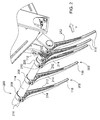
Figure 1 is a perspective view of a reel for an agricultural harvesting head in accordance with the present invention. -
Figure 2 is a close-up of a finger mounted to a bat on the reel ofFigure 1 . -
Figure 3 is a view of the finger ofFigure 2 removed from the bat. -
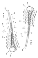
Figure 4 is a left side view of the finger ofFigure 3 . -
Figure 5 is a right side view of the finger ofFigure 3-4 . -
Figure 6 is a longitudinal cross-section of the finger ofFigures 3-5 . -
Figure 7 is a cross-sectional view of the finger ofFigures 3-6 taken in a direction perpendicular to the longitudinal extent. -
Figures 8-11 are cross sectional slices of the finger ofFigures 1-7 taken at section lines 8-8, 9-9, 10-10, and 11-11 inFigure 4 . -
Figure 12 is a cross-sectional perspective view through an alternative finger in which each of the struts of the embodiment ofFigures 1-11 have been rotated about their midpoints to be perpendicular at each end with respect to the front flange and the rear flange of the finger. -
Figure 13 is a cross-section of the alternative finger ofFigure 12 taken between two adjacent struts that are disposed perpendicular to the front flange and the rear flange of the finger. - In the discussion below, the terms "front", "forward", "in front of" and the like refer to the direction of travel of the real fingers engage the crop. This direction is indicated in the Figures by the directional arrow marked "V". The direction "V" is generally perpendicular to the longitudinal extent of the finger, and perpendicular to the longitudinal extent of the bat on which the finger is designed to be mounted.
- In the discussion below, the terms "rear", "rearward", "behind", "back", "backward" and the like refer to a direction opposite to the direction "V".
- In the discussion below, the terms "lateral", "transverse", "side-to-side" and the like refer to a direction parallel to the longitudinal extent of the bats on which the is designed to be mounted. In the discussion below, the terms "up", "upper", "higher" and the like refer to a direction towards the bat on which the finger is designed to be mounted. In the discussion below, the terms "down", "downward", "lower", and the like refer to a direction away from the bat on which the finger is designed to be mounted.
- Referring now to
Figure 1 , areel assembly 100 for an agricultural harvesting head is shown. Thereel assembly 100 includes areel 102 that is elongate, to which a leftend supporting arm 104, and a rightend supporting arm 106 are attached. - The
reel 102 is comprised of acentral tube 108 that is elongate to which six bat supports 110 are attached. Eachbat support 110 is spaced evenly apart from itsadjacent bat support 110 along the length of thecentral tube 108. Eachbat support 110 has sixbat mounts 112. - Each of the
bat mounts 112 on thebat support 110 supports sixbats 114. Eachbat mount 112 supports sixbats 114 that are equiangularly spaced about the circumference of thecentral tube 108, and are equidistant from the longitudinalrotational axis 116 of thecentral tube 108.Fingers 118 are fixed to each of the sixbats 114. Eachfinger 118 on abat 114 is spaced equidistantly from itsadjacent fingers 118. Thefingers 118 are distributed along substantially the entire length of eachbat 114. -
Finger 118 is an elongate member that has anupper end 200 that is configured to be fixed to bat 114, and alower end 202 that is configured to engage the upper portions of crop plants.Finger 118 tapers inwardly in a downward direction over substantially its entire length. Tapering occurs in a transverse direction, as well as a fore and aft direction. - Figure 118 has an
upper portion 204 that is in the form of an I-beam that extends in a direction parallel to the longitudinal extent of thefinger 118.Finger 118 has alower portion 206 that is solid in cross section. - The
upper end 200 includes astrap 208 that extends about thebat 114, and is secured to itself with afastener 210.Fastener 210 is a screw, bolt, or other threaded fastener. It may be a rivet or other flanged fastener made for permanent or semi-permanent attachment. - The
upper portion 204 offinger 118 comprises afront flange 212 that extends laterally and longitudinally. - The
upper portion 204 offinger 118 comprises arear flange 214 that extends laterally and longitudinally. - The
upper portion 204 offinger 118 comprises aweb 216 that extends in a fore and aft direction and is integrally formed with thefront flange 212 and therear flange 214. - The
front flange 212, therear flange 214, and theweb 216 form the I-beam structure. - The thickness of the
web 216 in a transverse direction is less than the thickness of thefront flange 212 in a fore-and-aft direction, and is less than the thickness of therear flange 214 in a fore-and-aft direction. - The extent of the
front flange 212 and the extent of therear flange 214 in the transverse direction are three times greater than the extent of theweb 216 in the transverse direction. - In another arrangement the extent of the
front flange 212 and the extent of therear flange 214 in the transverse direction are four times greater than the extent of theweb 216 in the transverse direction. - The
front flange 212, therear flange 214, and theweb 216 are configured as an I-beam, in which thefront flange 212 and therear flange 214 extend in a transverse direction more than a fore-and-aft direction, and theweb 216 extends in a fore-and-aft direction more than the transverse direction. It is this transversely extending flange versus fore and aft extending web that gives the upper portion of thefinger 118 its characteristic I-beam shape. - This I-beam shape changes, however, as the
finger 118 extends downward. Theupper portion 204 offinger 118 tapers inward from both side of the web in a lateral direction as it extends downwards. The lateral width of thefront flange 212 decreases as it extends downwards. The lateral width ofrear flange 214 decreases as it extends downward. - The
upper portion 204 offinger 118 tapers in a fore-and-aft direction as it extends downwards. The fore-and-aft extent of theweb 216 decreases as it extends downward. - The
upper portion 204 of thefinger 118 gradually transitions into thelower portion 206 of thefinger 118 by changing its cross sectional profile over tiny increments of length. As the fore and aft extent of theweb 216 decreases in a downward direction, the lateral width of theweb 216 simultaneously increases. This transition is best shown inFigures 8, 9, 10, and 11 . -
Figures 8, 9, 10, 11 , show successive cross-sectional slices of thefinger 118 taken at section lines 8-8, 9-9, 10-10, and 11-11 inFigure 4 . Each successive cross-sectional slice is located further down on the longitudinal extent of thefinger 118, - Referring now to
Figures 8, 9, 10, 11 , in each successive figure, the transverse extent of thefront flange 212 and therear flange 214 are successively reduced. Furthermore, the transverse extent of thefront flange 212 and therear flange 214 are substantially the same at each cross-section. This pattern is the same over the entire length of the finger 118: the transverse extent of thefront flange 212 and therear flange 214 are substantially the same over the entire lengths of thefront flange 212 and therear flange 214. - The
upper portion 204 offinger 118 comprises a plurality ofstruts 218. Eachstrut 218 is formed integral with theweb 216 and extends laterally away fromweb 216 in a direction parallel to thebat 114. Eachstrut 218 is integrally formed with therear flange 214 and extends forward away from therear flange 214 toward thefront flange 212. - In the arrangement illustrated in
Figures 1-11 , the transverse extent of eachstrut 218 is smaller at its forward end (e.g. where thestrut 218 is adjacent to the front flange 212), as compared to the transverse extent of eachstrut 218 at its rear end (e.g. where thestrut 218 is adjacent to the rear flange 214). - Under the typical loads experienced by the
finger 118, thelower end 202 of thefinger 118 is pushed backwards by the crop, placing thefront flange 212 in tension, and therear flange 214 in compression. This compression of therear flange 214 tends to cause therear flange 214 to buckle. - Thus, a benefit of the
web 216 is preventing the buckling of therear flange 214 during normal operation. Thefront flange 212 is strong enough that it will not tear, and thereby does not need as much support as therear flange 214 does. - By providing
struts 218 that extend substantially the entire width of therear flange 214 and extend for only a small portion of the width of thefront flange 212, thestruts 218 can provide additional strength to therear flange 214. - Some of the
struts 218 are arranged in a zigzag relationship in which several of thestruts 218 extend both downward and rearward from thefront flange 212 to therear flange 214. Thesestruts 218 are shown with the subscript "r" inFigures 4, 5 . - Some of the
struts 218 are arranged in a zigzag relationship in which several of thestruts 218 extend both downward and forward from thefront flange 212 to therear flange 214. Thesestruts 218 are shown with the subscript "f" inFigures 4, 5 . - Each
strut 218f is formed integral with a firstadjacent strut 218r at a forward end of the strut 218f. Said eachstrut 218f is formed integral with a secondadjacent strut 218r at a rearward end of said eachstrut 218f. - Each
strut 218r is formed integral with a firstadjacent strut 218f at a forward end of said each strut 218r. Said eachstrut 218r is formed integral with a secondadjacent strut 218f at a rearward end of said eachstrut 218r. - Each
strut 218f is formed integral with a firstadjacent strut 218r and withfront flange 212 at a forward end of the strut 218f. Said eachstrut 218f is formed integral with a secondadjacent strut 218r and with therear flange 214 at a rearward end of said eachstrut 218f. - Each
strut 218r is formed integral with a firstadjacent strut 218f and withfront flange 212 at a forward end of thestrut 218r. Eachstrut 218r is formed integral with a secondadjacent strut 218f and with therear flange 214 at a rearward end of said eachstrut 218r. - Others of the struts 218 (extend both downward and forward from the
rear flange 214 to thefront flange 212. Thesestruts 218 are shown with the subscript "f" inFigures 4, 5 . - These
struts 218 meet to definetriangular boxes 220 defined by two adjacent struts 218 (onestrut 218f and onestrut 218r) and thefront flange 212, and defined by two adjacent struts 218 (onestrut 218f and onestrut 218r) and therear flange 214. Thesetriangular boxes 220 are provided on both sides of thefinger 118, as can be seen best inFigures 4, 5 . - This arrangement of the struts 218 (i.e. some extending simultaneously downward and forward and some extending simultaneously downward and backward) provides additional torsional stability to the
finger 118. Even more torsional stability is provided by the arrangement of thesestruts 218 to definetriangular boxes 220. - Torsional stability is of particular importance since
finger 118 is curved forward at itslower end 202. This curvature is gradual and extends over substantially the entire length of thefront flange 212. This forward curvature permits thelower end 202 of thefinger 118 to engage the tops of the crop plant first. - The crop plants tend to be tangled, and therefore will exert transverse forces (i.e. a component of the total force that is generally parallel to the longitudinal extent of the bats 114).
- Due to the forward curvature of the
finger 118, these transverse forces tend to twist thefinger 118 at itslower end 202 to the left and to the right. - In an alternative arrangement, shown in
Figures 12 and 13 , eachstrut 218 has been rotated about a transversely extending axis extending through the front to rear midpoint of thestrut 218 until eachstrut 218 is substantially parallel to its two adjacent struts and equidistantly spaced therebetween. - In the arrangement of
Figures 12 and 13 ,strut 218 is arranged with respect to its adjacent structure and with respect to thefront flange 212 and therear flange 214 to define generallyrectangular boxes 222. Theserectangular boxes 222 are defined by thefront flange 212, therear flange 214, and twoadjacent struts 218. Thestruts 218, in the embodiment shown inFigures 12 and 13 , are arranged to extend perpendicular to thefront flange 212 and therear flange 214. Thestruts 218 in the embodiment shown inFigures 12 and 13 are configured to extend from theweb 216 to the outer edges of thefront flange 212 and therear flange 214. - In another alternative arrangement, not shown herein, the
struts 218 shown inFigures 1-11 can extend from theweb 216 to the outer edges of thefront flange 212 and therear flange 214 in the same fashion as they are shown inFigures 12, 13 . - Likewise, in an alternative arrangement, not shown herein, the
struts 218 shown inFigures 1-11 can extend perpendicular to thefront flange 212 and therear flange 214 to define similarrectangular boxes 222. - In all of the arrangement shown herein, the
web 216 is formed integral with thefront flange 212 and therear flange 214 and is fixed to these flanges at the transverse midpoint of thefront flange 212 and therear flange 214.
Claims (15)
- A finger (118) that is elongate and has a longitudinal extent, for a reel (102) of an agricultural harvesting head, the reel (102) having a plurality of bats (114) disposed about a longitudinal rotational axis (116), wherein each of the plurality of bats (114) is configured to support a plurality of the fingers (118) that are spaced apart and mounted side-by-side on each of the plurality of bats, the finger (118) comprising:a front flange (212) that extends in a longitudinal and a transverse direction;a rear flange (214) that extends in the longitudinal and the transverse direction and is spaced apart from the front flange;a web (216) that extends between the front flange (212) and the rear flange (214) and is integrally formed with the front flange (212) and the rear flange (214); andstruts (218) that are formed integral with the web (216) and with the rear flange (214) and that extend in a transverse direction.
- The finger of Claim 1, wherein adjacent struts (218) form a triangular box (220) with the front flange (212).
- The finger of Claim 1, wherein adjacent struts (218) form a triangular box (220) with the rear flange (214).
- The finger of Claim 1, wherein adjacent struts (218) form a rectangular box (222) with the front flange (212) and the rear flange (214).
- The finger of Claim 4, wherein adjacent struts (218) are generally parallel to each other and perpendicular to the front flange (212) and the rear flange (214).
- The finger of Claim 1, wherein the struts (218) extend in a lateral direction a greater distance adjacent to the rear flange (214) than adjacent to the front flange (212).
- The finger of Claim 1, wherein each adjacent pair of struts (218) meets at an acute angle at the front flange (212).
- The finger of Claim 1, wherein each adjacent pair of struts (218) meets at an acute angle at the rear flange (214).
- The finger of Claim 1, wherein each strut (218) is disposed at an acute angle with respect to the front flange (212), and is disposed at an acute angle with respect to the rear flange (214).
- The finger of Claim 1, wherein a thickness of the web (216) in a transverse direction is less than a thickness of the front flange (212) in a fore-and-aft direction.
- The finger of Claim 1, wherein a thickness of the web (216) in a transverse direction is less than a thickness of the rear flange (214) in a fore-and-aft direction.
- The finger of Claim 1, wherein an extent of the front flange (212) and an extent of the rear flange (214) in a transverse direction is at least three times an extent of the web (216) in the transverse direction.
- The finger of Claim 1, wherein an extent of the front flange (212) and an extent of the rear flange (214) in a transverse direction is at least four times an extent of the web (216) in the transverse direction.
- A reel (102) of an agricultural harvesting head comprising a finger according to one of the preceding claims.
- A harvesting head with a reel (102) according to claim 14.
Applications Claiming Priority (1)
| Application Number | Priority Date | Filing Date | Title |
|---|---|---|---|
| US13/873,309 US9338943B2 (en) | 2013-04-30 | 2013-04-30 | Reel finger |
Publications (3)
| Publication Number | Publication Date |
|---|---|
| EP2798940A2 true EP2798940A2 (en) | 2014-11-05 |
| EP2798940A3 EP2798940A3 (en) | 2014-12-24 |
| EP2798940B1 EP2798940B1 (en) | 2017-05-17 |
Family
ID=50336161
Family Applications (1)
| Application Number | Title | Priority Date | Filing Date |
|---|---|---|---|
| EP14160873.7A Active EP2798940B1 (en) | 2013-04-30 | 2014-03-20 | Reel finger |
Country Status (6)
| Country | Link |
|---|---|
| US (1) | US9338943B2 (en) |
| EP (1) | EP2798940B1 (en) |
| CN (1) | CN104126373B (en) |
| AU (1) | AU2014202217B2 (en) |
| BR (1) | BR102014010184B1 (en) |
| RU (1) | RU2664310C2 (en) |
Cited By (1)
| Publication number | Priority date | Publication date | Assignee | Title |
|---|---|---|---|---|
| EP4070644A1 (en) * | 2021-02-17 | 2022-10-12 | B. Strautmann & Söhne GmbH u. Co. KG | Zinc segment with an interior |
Families Citing this family (7)
| Publication number | Priority date | Publication date | Assignee | Title |
|---|---|---|---|---|
| US9872435B2 (en) | 2014-11-05 | 2018-01-23 | Hcc, Inc. | Harvester tine having a front-to-rear parting line in its strap and finger portion and one or more depressions on its finger portion |
| CA2986840C (en) * | 2015-06-11 | 2024-01-23 | Stw S.R.L. | Telescopic reel |
| US11058054B2 (en) | 2016-07-19 | 2021-07-13 | Duck Foot Parts Inc. | Harvesting tool |
| USD805561S1 (en) | 2016-07-19 | 2017-12-19 | Steven Ray Kastning | Harvesting tool |
| US10440890B1 (en) | 2016-07-19 | 2019-10-15 | Steven Ray Kastning | Harvesting tool |
| US11272663B2 (en) | 2018-03-01 | 2022-03-15 | Deere & Company | Harvester head reel with extendable bat |
| US12120981B2 (en) * | 2020-07-02 | 2024-10-22 | Deere & Company | Reel assembly with removable tines and method of use |
Family Cites Families (15)
| Publication number | Priority date | Publication date | Assignee | Title |
|---|---|---|---|---|
| US3796030A (en) * | 1972-10-16 | 1974-03-12 | Love J Co | Bat and tine construction for a harvester reel |
| US4459797A (en) * | 1982-09-30 | 1984-07-17 | Hart-Carter Company | Harvester reel pick-up bat construction |
| US4520620A (en) * | 1984-09-27 | 1985-06-04 | Hart-Carter Company | Harvester reel pickup tine |
| SU1253482A1 (en) * | 1984-11-19 | 1986-08-30 | Всесоюзный Ордена Трудового Красного Знамени Научно-Исследовательский Институт Сельскохозяйственного Машиностроения Им.В.П.Горячкина | Rake of reel |
| SU1375175A1 (en) * | 1985-10-25 | 1988-02-23 | Научно-производственное объединение по сельскохозяйственному машиностроению | Rake reel |
| US4901511A (en) * | 1988-10-13 | 1990-02-20 | Yarmashev Jury N | Harvester reel rake bar |
| US5507544A (en) * | 1995-01-09 | 1996-04-16 | Mcquade; Edmund J. | Jug handle holder |
| US6199357B1 (en) * | 1998-11-13 | 2001-03-13 | Alamo Group Inc. | Reel pickup tine |
| US6324823B1 (en) * | 1999-09-29 | 2001-12-04 | Macdon Industries Ltd. | Mounting a finger on the bat of a harvesting header |
| CA2284432C (en) * | 1999-10-01 | 2006-08-01 | Macdon Industries Ltd. | Mounting a finger on the bat of a harvesting header |
| US7124564B2 (en) * | 2003-10-30 | 2006-10-24 | Plastic Designs, Inc. | Harvester reel tine repair |
| DE102005052394A1 (en) * | 2005-10-31 | 2007-05-03 | Gustav Schumacher | Reel tine for mounting carrier body of reel, has gripping element, mounting element, connection section and clip section |
| CN201360432Y (en) * | 2008-12-22 | 2009-12-16 | 上海市农业机械研究所 | Plastic tooth shifting device for reel of harvesting machine |
| CA2665580C (en) * | 2009-05-07 | 2012-04-03 | Macdon Industries Ltd. | Extruded bat for the reel of a crop harvesting header |
| US9095095B2 (en) * | 2013-03-15 | 2015-08-04 | Agco Corporation | Clip on reel tine |
-
2013
- 2013-04-30 US US13/873,309 patent/US9338943B2/en active Active
-
2014
- 2014-03-20 EP EP14160873.7A patent/EP2798940B1/en active Active
- 2014-04-16 RU RU2014115335A patent/RU2664310C2/en active
- 2014-04-23 AU AU2014202217A patent/AU2014202217B2/en not_active Ceased
- 2014-04-28 BR BR102014010184A patent/BR102014010184B1/en active IP Right Grant
- 2014-04-29 CN CN201410177380.6A patent/CN104126373B/en active Active
Non-Patent Citations (1)
| Title |
|---|
| None |
Cited By (1)
| Publication number | Priority date | Publication date | Assignee | Title |
|---|---|---|---|---|
| EP4070644A1 (en) * | 2021-02-17 | 2022-10-12 | B. Strautmann & Söhne GmbH u. Co. KG | Zinc segment with an interior |
Also Published As
| Publication number | Publication date |
|---|---|
| EP2798940A3 (en) | 2014-12-24 |
| AU2014202217A1 (en) | 2014-11-13 |
| CN104126373A (en) | 2014-11-05 |
| US20140318097A1 (en) | 2014-10-30 |
| CN104126373B (en) | 2018-01-02 |
| AU2014202217B2 (en) | 2017-11-02 |
| RU2014115335A (en) | 2015-10-27 |
| BR102014010184B1 (en) | 2019-12-24 |
| RU2664310C2 (en) | 2018-08-16 |
| US9338943B2 (en) | 2016-05-17 |
| EP2798940B1 (en) | 2017-05-17 |
| BR102014010184A2 (en) | 2018-10-30 |
Similar Documents
| Publication | Publication Date | Title |
|---|---|---|
| EP2798940B1 (en) | Reel finger | |
| DE102011081403B4 (en) | Flexible cutting unit with cross conveyor belts and swivel geometry | |
| EP3287001B1 (en) | Lightweight stalk roll knife | |
| US7520117B2 (en) | Auger stripper assembly for a combine corn head | |
| DE102011081400B4 (en) | Cutting unit with transverse conveyor belts and predetermined breaking point | |
| EP1820386B1 (en) | Combine head frame | |
| EP3167704A1 (en) | Row unit for a corn head assembly having a top plate with a structured surface | |
| US7644567B2 (en) | Flexible tall crop pusher | |
| US10925215B2 (en) | Slat-bar cross-members in a feederhouse crop-conveying system | |
| EP3613271B1 (en) | Stalk roll with blade inserts for agricultural combine | |
| US8572942B2 (en) | Curved profile seed pans | |
| US20150141098A1 (en) | Inclined conveyor for combine harvesters | |
| US9844180B2 (en) | Header frame having an adjustably mounted tool bar bracketing assembly | |
| US20150143787A1 (en) | High rise crop lifter | |
| EP2700295A1 (en) | Harvesting head with crop deflector | |
| US8863486B2 (en) | Corn stalk guide system | |
| US20130291511A1 (en) | Variable length header truss for harvesting header | |
| CN220776601U (en) | Novel cereal cutting table divider structure | |
| US9807927B2 (en) | Overlapping sickle section for a knife assembly | |
| CN215530041U (en) | Harvester and row unit and separator thereof | |
| CN205912497U (en) | Chinese sorghum harvester divider | |
| BE398645A (en) | ||
| JPH0795895B2 (en) | Combine threshing equipment | |
| EP4070644A1 (en) | Zinc segment with an interior |
Legal Events
| Date | Code | Title | Description |
|---|---|---|---|
| PUAI | Public reference made under article 153(3) epc to a published international application that has entered the european phase |
Free format text: ORIGINAL CODE: 0009012 |
|
| 17P | Request for examination filed |
Effective date: 20140320 |
|
| AK | Designated contracting states |
Kind code of ref document: A2 Designated state(s): AL AT BE BG CH CY CZ DE DK EE ES FI FR GB GR HR HU IE IS IT LI LT LU LV MC MK MT NL NO PL PT RO RS SE SI SK SM TR |
|
| AX | Request for extension of the european patent |
Extension state: BA ME |
|
| PUAL | Search report despatched |
Free format text: ORIGINAL CODE: 0009013 |
|
| AK | Designated contracting states |
Kind code of ref document: A3 Designated state(s): AL AT BE BG CH CY CZ DE DK EE ES FI FR GB GR HR HU IE IS IT LI LT LU LV MC MK MT NL NO PL PT RO RS SE SI SK SM TR |
|
| AX | Request for extension of the european patent |
Extension state: BA ME |
|
| RIC1 | Information provided on ipc code assigned before grant |
Ipc: A01D 57/02 20060101AFI20141118BHEP |
|
| R17P | Request for examination filed (corrected) |
Effective date: 20150624 |
|
| RBV | Designated contracting states (corrected) |
Designated state(s): AL AT BE BG CH CY CZ DE DK EE ES FI FR GB GR HR HU IE IS IT LI LT LU LV MC MK MT NL NO PL PT RO RS SE SI SK SM TR |
|
| 17Q | First examination report despatched |
Effective date: 20160307 |
|
| GRAP | Despatch of communication of intention to grant a patent |
Free format text: ORIGINAL CODE: EPIDOSNIGR1 |
|
| INTG | Intention to grant announced |
Effective date: 20170102 |
|
| GRAS | Grant fee paid |
Free format text: ORIGINAL CODE: EPIDOSNIGR3 |
|
| GRAA | (expected) grant |
Free format text: ORIGINAL CODE: 0009210 |
|
| AK | Designated contracting states |
Kind code of ref document: B1 Designated state(s): AL AT BE BG CH CY CZ DE DK EE ES FI FR GB GR HR HU IE IS IT LI LT LU LV MC MK MT NL NO PL PT RO RS SE SI SK SM TR |
|
| REG | Reference to a national code |
Ref country code: GB Ref legal event code: FG4D |
|
| REG | Reference to a national code |
Ref country code: CH Ref legal event code: EP |
|
| REG | Reference to a national code |
Ref country code: IE Ref legal event code: FG4D |
|
| REG | Reference to a national code |
Ref country code: AT Ref legal event code: REF Ref document number: 893585 Country of ref document: AT Kind code of ref document: T Effective date: 20170615 |
|
| REG | Reference to a national code |
Ref country code: DE Ref legal event code: R096 Ref document number: 602014009828 Country of ref document: DE |
|
| REG | Reference to a national code |
Ref country code: NL Ref legal event code: MP Effective date: 20170517 |
|
| REG | Reference to a national code |
Ref country code: LT Ref legal event code: MG4D |
|
| REG | Reference to a national code |
Ref country code: AT Ref legal event code: MK05 Ref document number: 893585 Country of ref document: AT Kind code of ref document: T Effective date: 20170517 |
|
| PG25 | Lapsed in a contracting state [announced via postgrant information from national office to epo] |
Ref country code: HR Free format text: LAPSE BECAUSE OF FAILURE TO SUBMIT A TRANSLATION OF THE DESCRIPTION OR TO PAY THE FEE WITHIN THE PRESCRIBED TIME-LIMIT Effective date: 20170517 Ref country code: NO Free format text: LAPSE BECAUSE OF FAILURE TO SUBMIT A TRANSLATION OF THE DESCRIPTION OR TO PAY THE FEE WITHIN THE PRESCRIBED TIME-LIMIT Effective date: 20170817 Ref country code: ES Free format text: LAPSE BECAUSE OF FAILURE TO SUBMIT A TRANSLATION OF THE DESCRIPTION OR TO PAY THE FEE WITHIN THE PRESCRIBED TIME-LIMIT Effective date: 20170517 Ref country code: LT Free format text: LAPSE BECAUSE OF FAILURE TO SUBMIT A TRANSLATION OF THE DESCRIPTION OR TO PAY THE FEE WITHIN THE PRESCRIBED TIME-LIMIT Effective date: 20170517 Ref country code: GR Free format text: LAPSE BECAUSE OF FAILURE TO SUBMIT A TRANSLATION OF THE DESCRIPTION OR TO PAY THE FEE WITHIN THE PRESCRIBED TIME-LIMIT Effective date: 20170818 Ref country code: FI Free format text: LAPSE BECAUSE OF FAILURE TO SUBMIT A TRANSLATION OF THE DESCRIPTION OR TO PAY THE FEE WITHIN THE PRESCRIBED TIME-LIMIT Effective date: 20170517 Ref country code: AT Free format text: LAPSE BECAUSE OF FAILURE TO SUBMIT A TRANSLATION OF THE DESCRIPTION OR TO PAY THE FEE WITHIN THE PRESCRIBED TIME-LIMIT Effective date: 20170517 |
|
| PG25 | Lapsed in a contracting state [announced via postgrant information from national office to epo] |
Ref country code: PL Free format text: LAPSE BECAUSE OF FAILURE TO SUBMIT A TRANSLATION OF THE DESCRIPTION OR TO PAY THE FEE WITHIN THE PRESCRIBED TIME-LIMIT Effective date: 20170517 Ref country code: RS Free format text: LAPSE BECAUSE OF FAILURE TO SUBMIT A TRANSLATION OF THE DESCRIPTION OR TO PAY THE FEE WITHIN THE PRESCRIBED TIME-LIMIT Effective date: 20170517 Ref country code: IS Free format text: LAPSE BECAUSE OF FAILURE TO SUBMIT A TRANSLATION OF THE DESCRIPTION OR TO PAY THE FEE WITHIN THE PRESCRIBED TIME-LIMIT Effective date: 20170917 Ref country code: NL Free format text: LAPSE BECAUSE OF FAILURE TO SUBMIT A TRANSLATION OF THE DESCRIPTION OR TO PAY THE FEE WITHIN THE PRESCRIBED TIME-LIMIT Effective date: 20170517 Ref country code: LV Free format text: LAPSE BECAUSE OF FAILURE TO SUBMIT A TRANSLATION OF THE DESCRIPTION OR TO PAY THE FEE WITHIN THE PRESCRIBED TIME-LIMIT Effective date: 20170517 Ref country code: SE Free format text: LAPSE BECAUSE OF FAILURE TO SUBMIT A TRANSLATION OF THE DESCRIPTION OR TO PAY THE FEE WITHIN THE PRESCRIBED TIME-LIMIT Effective date: 20170517 Ref country code: BG Free format text: LAPSE BECAUSE OF FAILURE TO SUBMIT A TRANSLATION OF THE DESCRIPTION OR TO PAY THE FEE WITHIN THE PRESCRIBED TIME-LIMIT Effective date: 20170817 |
|
| PG25 | Lapsed in a contracting state [announced via postgrant information from national office to epo] |
Ref country code: RO Free format text: LAPSE BECAUSE OF FAILURE TO SUBMIT A TRANSLATION OF THE DESCRIPTION OR TO PAY THE FEE WITHIN THE PRESCRIBED TIME-LIMIT Effective date: 20170517 Ref country code: CZ Free format text: LAPSE BECAUSE OF FAILURE TO SUBMIT A TRANSLATION OF THE DESCRIPTION OR TO PAY THE FEE WITHIN THE PRESCRIBED TIME-LIMIT Effective date: 20170517 Ref country code: DK Free format text: LAPSE BECAUSE OF FAILURE TO SUBMIT A TRANSLATION OF THE DESCRIPTION OR TO PAY THE FEE WITHIN THE PRESCRIBED TIME-LIMIT Effective date: 20170517 Ref country code: SK Free format text: LAPSE BECAUSE OF FAILURE TO SUBMIT A TRANSLATION OF THE DESCRIPTION OR TO PAY THE FEE WITHIN THE PRESCRIBED TIME-LIMIT Effective date: 20170517 Ref country code: EE Free format text: LAPSE BECAUSE OF FAILURE TO SUBMIT A TRANSLATION OF THE DESCRIPTION OR TO PAY THE FEE WITHIN THE PRESCRIBED TIME-LIMIT Effective date: 20170517 |
|
| REG | Reference to a national code |
Ref country code: DE Ref legal event code: R097 Ref document number: 602014009828 Country of ref document: DE |
|
| PG25 | Lapsed in a contracting state [announced via postgrant information from national office to epo] |
Ref country code: SM Free format text: LAPSE BECAUSE OF FAILURE TO SUBMIT A TRANSLATION OF THE DESCRIPTION OR TO PAY THE FEE WITHIN THE PRESCRIBED TIME-LIMIT Effective date: 20170517 |
|
| PLBE | No opposition filed within time limit |
Free format text: ORIGINAL CODE: 0009261 |
|
| STAA | Information on the status of an ep patent application or granted ep patent |
Free format text: STATUS: NO OPPOSITION FILED WITHIN TIME LIMIT |
|
| REG | Reference to a national code |
Ref country code: FR Ref legal event code: PLFP Year of fee payment: 5 |
|
| 26N | No opposition filed |
Effective date: 20180220 |
|
| PG25 | Lapsed in a contracting state [announced via postgrant information from national office to epo] |
Ref country code: SI Free format text: LAPSE BECAUSE OF FAILURE TO SUBMIT A TRANSLATION OF THE DESCRIPTION OR TO PAY THE FEE WITHIN THE PRESCRIBED TIME-LIMIT Effective date: 20170517 |
|
| REG | Reference to a national code |
Ref country code: CH Ref legal event code: PL |
|
| GBPC | Gb: european patent ceased through non-payment of renewal fee |
Effective date: 20180320 |
|
| PG25 | Lapsed in a contracting state [announced via postgrant information from national office to epo] |
Ref country code: MC Free format text: LAPSE BECAUSE OF FAILURE TO SUBMIT A TRANSLATION OF THE DESCRIPTION OR TO PAY THE FEE WITHIN THE PRESCRIBED TIME-LIMIT Effective date: 20170517 |
|
| REG | Reference to a national code |
Ref country code: BE Ref legal event code: MM Effective date: 20180331 |
|
| REG | Reference to a national code |
Ref country code: IE Ref legal event code: MM4A |
|
| PG25 | Lapsed in a contracting state [announced via postgrant information from national office to epo] |
Ref country code: LU Free format text: LAPSE BECAUSE OF NON-PAYMENT OF DUE FEES Effective date: 20180320 |
|
| PG25 | Lapsed in a contracting state [announced via postgrant information from national office to epo] |
Ref country code: IE Free format text: LAPSE BECAUSE OF NON-PAYMENT OF DUE FEES Effective date: 20180320 |
|
| PG25 | Lapsed in a contracting state [announced via postgrant information from national office to epo] |
Ref country code: GB Free format text: LAPSE BECAUSE OF NON-PAYMENT OF DUE FEES Effective date: 20180320 Ref country code: LI Free format text: LAPSE BECAUSE OF NON-PAYMENT OF DUE FEES Effective date: 20180331 Ref country code: CH Free format text: LAPSE BECAUSE OF NON-PAYMENT OF DUE FEES Effective date: 20180331 Ref country code: BE Free format text: LAPSE BECAUSE OF NON-PAYMENT OF DUE FEES Effective date: 20180331 |
|
| PG25 | Lapsed in a contracting state [announced via postgrant information from national office to epo] |
Ref country code: MT Free format text: LAPSE BECAUSE OF NON-PAYMENT OF DUE FEES Effective date: 20180320 |
|
| PG25 | Lapsed in a contracting state [announced via postgrant information from national office to epo] |
Ref country code: TR Free format text: LAPSE BECAUSE OF FAILURE TO SUBMIT A TRANSLATION OF THE DESCRIPTION OR TO PAY THE FEE WITHIN THE PRESCRIBED TIME-LIMIT Effective date: 20170517 |
|
| PG25 | Lapsed in a contracting state [announced via postgrant information from national office to epo] |
Ref country code: HU Free format text: LAPSE BECAUSE OF FAILURE TO SUBMIT A TRANSLATION OF THE DESCRIPTION OR TO PAY THE FEE WITHIN THE PRESCRIBED TIME-LIMIT; INVALID AB INITIO Effective date: 20140320 Ref country code: PT Free format text: LAPSE BECAUSE OF FAILURE TO SUBMIT A TRANSLATION OF THE DESCRIPTION OR TO PAY THE FEE WITHIN THE PRESCRIBED TIME-LIMIT Effective date: 20170517 |
|
| PG25 | Lapsed in a contracting state [announced via postgrant information from national office to epo] |
Ref country code: CY Free format text: LAPSE BECAUSE OF FAILURE TO SUBMIT A TRANSLATION OF THE DESCRIPTION OR TO PAY THE FEE WITHIN THE PRESCRIBED TIME-LIMIT Effective date: 20170517 Ref country code: MK Free format text: LAPSE BECAUSE OF NON-PAYMENT OF DUE FEES Effective date: 20170517 |
|
| PG25 | Lapsed in a contracting state [announced via postgrant information from national office to epo] |
Ref country code: AL Free format text: LAPSE BECAUSE OF FAILURE TO SUBMIT A TRANSLATION OF THE DESCRIPTION OR TO PAY THE FEE WITHIN THE PRESCRIBED TIME-LIMIT Effective date: 20170517 |
|
| PGFP | Annual fee paid to national office [announced via postgrant information from national office to epo] |
Ref country code: IT Payment date: 20220322 Year of fee payment: 9 |
|
| PG25 | Lapsed in a contracting state [announced via postgrant information from national office to epo] |
Ref country code: IT Free format text: LAPSE BECAUSE OF NON-PAYMENT OF DUE FEES Effective date: 20230320 |
|
| PGFP | Annual fee paid to national office [announced via postgrant information from national office to epo] |
Ref country code: DE Payment date: 20260219 Year of fee payment: 13 |
|
| PGFP | Annual fee paid to national office [announced via postgrant information from national office to epo] |
Ref country code: FR Payment date: 20260325 Year of fee payment: 13 |