EP2798728B1 - Motor cooling system - Google Patents
Motor cooling system Download PDFInfo
- Publication number
- EP2798728B1 EP2798728B1 EP12809916.5A EP12809916A EP2798728B1 EP 2798728 B1 EP2798728 B1 EP 2798728B1 EP 12809916 A EP12809916 A EP 12809916A EP 2798728 B1 EP2798728 B1 EP 2798728B1
- Authority
- EP
- European Patent Office
- Prior art keywords
- gap
- armature coil
- motor
- air
- gaps
- Prior art date
- Legal status (The legal status is an assumption and is not a legal conclusion. Google has not performed a legal analysis and makes no representation as to the accuracy of the status listed.)
- Active
Links
Images




Classifications
-
- H—ELECTRICITY
- H02—GENERATION; CONVERSION OR DISTRIBUTION OF ELECTRIC POWER
- H02K—DYNAMO-ELECTRIC MACHINES
- H02K9/00—Arrangements for cooling or ventilating
- H02K9/02—Arrangements for cooling or ventilating by ambient air flowing through the machine
- H02K9/04—Arrangements for cooling or ventilating by ambient air flowing through the machine having means for generating a flow of cooling medium
-
- H—ELECTRICITY
- H02—GENERATION; CONVERSION OR DISTRIBUTION OF ELECTRIC POWER
- H02K—DYNAMO-ELECTRIC MACHINES
- H02K41/00—Propulsion systems in which a rigid body is moved along a path due to dynamo-electric interaction between the body and a magnetic field travelling along the path
- H02K41/02—Linear motors; Sectional motors
Definitions
- a linear motor is an electric motor that generates a linear force along its length. The operation of such motors generates a significant amount of heat. Because many of the components of a linear motor, including, in particular, the armature coils and associated magnetic cores, are sensitive to temperature, cooling systems are provided to avoid a deterioration in motor performance.
- one approach to cooling a linear motor 100 is to place a heat sink 102 on either side of the motor. Heat generated during the operation of motor 100 is removed by conduction into heat sink 102. A fan bank 104 cools heat sink 102, thus dispersing the heat into the surrounding atmosphere and cooling motor 100.
- JPH0297266 discloses a double sided linear motor.
- JPH05336703 discloses a sensor to detect abnormalities in the temperature of a linear motor to prevent burning.
- JPH08280167 discloses a linear motor.
- US2010181848 discloses an electronic-circuit-component mounting machine including a linear motor.
- US6114781 discloses a cooling system for a linear or planar motor.
- JPS63283460 discloses a linear motor to permit effective cooling.
- US2007278864 discloses a cooling apparatus for a linear motor.
- an apparatus in a general aspect, as set forth in claim 1, includes a linear motor configured to output a linear force along its length.
- the linear motor includes an internal housing, a first armature coil disposed within the internal housing and separated from the internal housing by an upper gap and separated from the central support core by a first side gap, a first magnetic core associated with the armature coil.
- a second armature coil disposed within the internal housing, wherein the second armature coil is separated from the first armature coil by a central gap, separated from the internal housing by a lower gap, and separated from the central support core by a second side gap; and a second magnetic core associated with the second armature coil.
- the apparatus also includes a fan configured to cause air to flow in the upper gap, the first side gap, the central gap, the lower gap and the second side gap, and to blow air directly across the armature coils and magnetic cores with the air flow generally along the length of the motor.
- a geometry or size of the gaps is designed via an iterative process to maximize heat transfer based on operating temperatures of the armature coils and magnetic cores, properties of the air flow at operating temperatures, performance curves of the fan, or arrangement of the fan.
- Embodiments may include one or more of the following.
- the air flow in the gap causes cooling of at least one armature coil or magnetic core.
- the apparatus further includes a plurality of fans.
- An arrangement of the plurality of fans is determined to maximize at least one of flow velocity through the linear motor and heat transfer between the air and the armature coils.
- the fan is configured to cause turbulent air flow in the gaps.
- a size of the gaps is selected to cause turbulent air flow in the gaps.
- a size of the gaps is selected to maximize heat transfer between the air and the armature coil.
- the apparatus further includes a third armature coil; and a fourth armature coil adjacent to the third armature coil, the third armature coil separated from the fourth armature coil by a second central gap.
- the fan is configured to cause air to flow in the second coil gap.
- the linear motor is an electromagnetic motor.
- the apparatus further includes an inlet port is disposed on a first end of the linear motor, the fan disposed in the inlet port; and an exhaust port disposed on a second end of the electric machine opposite the inlet port.
- a method includes providing an linear motor.
- the linear motor includes an internal housing, an armature coil disposed within the internal housing and separated from the internal housing by a gap, and a magnetic core associated with the armature coil.
- the method further includes causing air to flow in the gap between the armature coil and the internal housing.
- Embodiments include the following.
- Causing air to flow in the gap causes cooling of at least one of the armature coil and the magnetic core.
- Causing air to flow in the gap comprises blowing air directly across the armature coil.
- Causing air to flow in the gap causes turbulent air flow in the gap.
- the method further includes determining a size of the gap in order to cause turbulent air flow in the gap.
- the method further includes determining a size of the gap in order to maximize heat transfer between the air and the armature coil.
- the systems described herein have fewer parts and are less complex than conventional motor cooling systems and thus can be implemented for lower cost. Gaps between armature coils within the motor allow for high cooling efficiency without compromising motor performance, such as the output force of the motor.
- the ability to cool the motor more efficiently allows the motor to be fabricated with conventional, lower cost lamination steel rather than higher grade steel, thus further reducing the fabrication cost of the motor.
- a linear motor 200 outputs a linear force along its length (denoted as the x-axis).
- Motor 200 is formed of an external housing 201 which houses an internal body 203.
- the internal body 203 includes four armature coils 202a, 202b, 202c, 202d, each with an associated magnetic core 204a, 204b, 204c, 204d, respectively.
- motor 200 generates a significant amount of heat, primarily from current flowing through the armature coils 202.
- the performance of the motor components, and in particular the magnetic cores 204 decreases with increasing motor temperature.
- a forced air, convection cooling system is employed to dissipate the heat generated by motor 200.
- a fan bank 206 is positioned at an inlet 208 on a front face 210 of the motor.
- Fan bank 206 includes one or more fans 212 that blow air directly into the interior of motor 200.
- the air flow is generally along the length of armature coils 202 (i.e., along the x-axis) and serves to cool the armature coils and associated magnetic cores 204.
- Motor 200 is designed with a straight flow-through design in which flow restrictions, such as turns, bends, or large changes in cross-sectional area, are minimized.
- a filter 219 is positioned at inlet 208 prior to fan bank 206 and serves to filter the air that is drawn into the motor, thus avoiding contamination of the motor components.
- Gaps 222-228 adjacent to the armature coils 202 allow a large fraction of the surface area of the armature coils to be exposed to the circulating air, facilitating heat transfer from the coils to the air.
- a central gap 222a separates armature coils 202a and 202b
- a central gap 222b separates armature coils 202c and 202d.
- Upper gaps 224a and 224b separate armature coils 202a and 202c, respectively, from the top of an internal housing 220.
- Lower gaps 226a and 226b separate armature coils 202b and 202d, respectively, from the bottom of housing 220.
- Side gaps 228a, 228b, 228c, and 228d separate armature coils 202a, 202b, 202c, and 202d, respectively, from a central support core 229 of the housing 220.
- High velocity air flow enhances the heat transfer coefficient between the armature coils 202 and the circulating air.
- the volume of space available for air flow i.e., the size and geometry of the gaps) affects the system impedance to air flow and thus influences the velocity of the air passing through the motor.
- the air flow velocity is also dependent upon the performance of fan bank 206, as well as on environmental factors such as temperature and air density.
- the heat transfer coefficient is maximized for turbulent air flow through the motor.
- Turbulent air flow can be achieved by causing air of sufficiently high velocity to flow in gaps 222-228, which is effected by optimizing the fan arrangement and performance and the gap geometry.
- cost and manufacturing considerations dictate that a motor of smaller volume and with a minimum number of fans is desirable.
- the gap geometry and fan arrangement are determined via an iterative process which aims to both maximize the heat transfer coefficient and minimize manufacturing cost.
- the amount of heat dissipated by the armature coils 202 is generally known.
- Factors such as the maximum allowable operating temperature of the armature coils 202 and magnets 204, the properties of the fluid (i.e., the circulating air) at the operating temperature, the airflow impedance of the motor, the fan performance curves, and the fan arrangement and cost are used as parameters in a model of the motor and cooling system.
- the design of the motor is determined to optimize the performance of the cooling system.
- the heat transfer coefficient that is sufficient to limit the temperatures of sensitive motor components can be calculated. Because the heat transfer coefficient is a function of the properties of the fluid, the flow velocity, and the flow geometry, it is possible to iterate a motor design in order to optimize the design for performance and cost. For instance, reducing the gap between the coils increases the impedance of the motor to air flow; to compensate for the increased impedance, the fan performance is increased to produce sufficient velocity to achieve the desired heat transfer coefficient. A larger gap between the coils will lower the air flow impedance but generally necessitates higher air flow rates to obtain the desired heat transfer coefficient. Thus, in general, an iterative process using motor impedance (i.e., geometry and/or gap size), fan performance, and cost as variables is employed to optimize the design of the motor.
- motor impedance i.e., geometry and/or gap size
- a motor designed based on such an iterative process produces 7.5 kN of force output and dissipates about 1.8 kW of heat through its four armature coils, or 450 Watts per coil.
- the gaps above and between the coils are 10 mm.
- the motor has external dimensions of 44.5 cm x 27.2 cm x 43.7 cm and weighs approximately 95 kg.
- gaps 222-228 is also subject to maintaining suitable magnetic performance of the motor components.
- the magnet transition line i.e., the N-to-S magnetic orientation change
- this alignment of the magnet transition line is maintained.
- the inclusion of the gaps between the armature coils increases the distance between the poles but continues to keep the magnetic transition distance aligned with the pole face centers.
Landscapes
- Engineering & Computer Science (AREA)
- Power Engineering (AREA)
- Physics & Mathematics (AREA)
- Chemical & Material Sciences (AREA)
- Combustion & Propulsion (AREA)
- Electromagnetism (AREA)
- Motor Or Generator Cooling System (AREA)
Description
- A linear motor is an electric motor that generates a linear force along its length. The operation of such motors generates a significant amount of heat. Because many of the components of a linear motor, including, in particular, the armature coils and associated magnetic cores, are sensitive to temperature, cooling systems are provided to avoid a deterioration in motor performance.
- Referring to
Fig. 1 , one approach to cooling alinear motor 100 is to place aheat sink 102 on either side of the motor. Heat generated during the operation ofmotor 100 is removed by conduction intoheat sink 102. Afan bank 104 coolsheat sink 102, thus dispersing the heat into the surrounding atmosphere and coolingmotor 100.
JPH0297266 discloses a double sided linear motor.
JPH05336703 discloses a sensor to detect abnormalities in the temperature of a linear motor to prevent burning.
JPH08280167 discloses a linear motor.
US2010181848 discloses an electronic-circuit-component mounting machine including a linear motor.
US6114781 discloses a cooling system for a linear or planar motor.
JPS63283460 discloses a linear motor to permit effective cooling.
US2007278864 discloses a cooling apparatus for a linear motor. - In a general aspect, as set forth in claim 1, an apparatus includes a linear motor configured to output a linear force along its length. The linear motor includes an internal housing, a first armature coil disposed within the internal housing and separated from the internal housing by an upper gap and separated from the central support core by a first side gap, a first magnetic core associated with the armature coil. A second armature coil disposed within the internal housing, wherein the second armature coil is separated from the first armature coil by a central gap, separated from the internal housing by a lower gap, and separated from the central support core by a second side gap; and a second magnetic core associated with the second armature coil. The apparatus also includes a fan configured to cause air to flow in the upper gap, the first side gap, the central gap, the lower gap and the second side gap, and to blow air directly across the armature coils and magnetic cores with the air flow generally along the length of the motor. A geometry or size of the gaps is designed via an iterative process to maximize heat transfer based on operating temperatures of the armature coils and magnetic cores, properties of the air flow at operating temperatures, performance curves of the fan, or arrangement of the fan.
- Embodiments may include one or more of the following.
- The air flow in the gap causes cooling of at least one armature coil or magnetic core.
- The apparatus further includes a plurality of fans. An arrangement of the plurality of fans is determined to maximize at least one of flow velocity through the linear motor and heat transfer between the air and the armature coils.
- The fan is configured to cause turbulent air flow in the gaps.
- A size of the gaps is selected to cause turbulent air flow in the gaps. A size of the gaps is selected to maximize heat transfer between the air and the armature coil.
- The apparatus further includes a third armature coil; and a fourth armature coil adjacent to the third armature coil, the third armature coil separated from the fourth armature coil by a second central gap. The fan is configured to cause air to flow in the second coil gap.
- The linear motor is an electromagnetic motor.
- The apparatus further includes an inlet port is disposed on a first end of the linear motor, the fan disposed in the inlet port; and an exhaust port disposed on a second end of the electric machine opposite the inlet port.
- Disclosed but not claimed, a method includes providing an linear motor. The linear motor includes an internal housing, an armature coil disposed within the internal housing and separated from the internal housing by a gap, and a magnetic core associated with the armature coil. The method further includes causing air to flow in the gap between the armature coil and the internal housing.
- Embodiments include the following.
- Causing air to flow in the gap causes cooling of at least one of the armature coil and the magnetic core. Causing air to flow in the gap comprises blowing air directly across the armature coil. Causing air to flow in the gap causes turbulent air flow in the gap.
- The method further includes determining a size of the gap in order to cause turbulent air flow in the gap. The method further includes determining a size of the gap in order to maximize heat transfer between the air and the armature coil.
- Among other advantages, the systems described herein have fewer parts and are less complex than conventional motor cooling systems and thus can be implemented for lower cost. Gaps between armature coils within the motor allow for high cooling efficiency without compromising motor performance, such as the output force of the motor. The ability to cool the motor more efficiently allows the motor to be fabricated with conventional, lower cost lamination steel rather than higher grade steel, thus further reducing the fabrication cost of the motor.
- Other features and advantages of the invention are apparent from the following description and from the claims.
-
-
Fig. 1 is a diagram of a prior art motor. -
Fig. 2 is a diagram of a motor cooled by forced air cooling. -
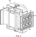
Fig. 3 is a diagram of internal components of the motor ofFig. 2 . -
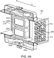
Fig. 4A is a cut-away perspective view of the internal components ofFig. 3 . -
Fig. 4B is a cut-away front view of the internal components ofFig. 3 . -
Fig. 4C is a cut-away side view of the internal components ofFig. 3 . - Referring to
Figs. 2 and3 , alinear motor 200 outputs a linear force along its length (denoted as the x-axis).Motor 200 is formed of anexternal housing 201 which houses aninternal body 203. Referring also toFigs. 4A-4C , theinternal body 203 includes fourarmature coils magnetic core motor 200 generates a significant amount of heat, primarily from current flowing through the armature coils 202. The performance of the motor components, and in particular the magnetic cores 204, decreases with increasing motor temperature. - A forced air, convection cooling system is employed to dissipate the heat generated by
motor 200. In particular, afan bank 206 is positioned at aninlet 208 on afront face 210 of the motor.Fan bank 206 includes one ormore fans 212 that blow air directly into the interior ofmotor 200. The air flow is generally along the length of armature coils 202 (i.e., along the x-axis) and serves to cool the armature coils and associated magnetic cores 204.Motor 200 is designed with a straight flow-through design in which flow restrictions, such as turns, bends, or large changes in cross-sectional area, are minimized. This unobstructed design allows air to flow through the motor at high velocity, which provides a high heat transfer coefficient between the air and the motor components. The air exits the motor via anexhaust port 216 on arear face 218 of the motor. In some embodiments, afilter 219 is positioned atinlet 208 prior tofan bank 206 and serves to filter the air that is drawn into the motor, thus avoiding contamination of the motor components. - In the interior of
motor 200, open space is provided to facilitate air flow across armature coils 202 and magnetic cores 204. Gaps 222-228 adjacent to the armature coils 202 allow a large fraction of the surface area of the armature coils to be exposed to the circulating air, facilitating heat transfer from the coils to the air. In particular, acentral gap 222a separatesarmature coils central gap 222b separates armature coils 202c and 202d.Upper gaps separate armature coils internal housing 220.Lower gaps separate armature coils housing 220.Side gaps separate armature coils central support core 229 of thehousing 220. - High velocity air flow enhances the heat transfer coefficient between the armature coils 202 and the circulating air. The volume of space available for air flow (i.e., the size and geometry of the gaps) affects the system impedance to air flow and thus influences the velocity of the air passing through the motor. The air flow velocity is also dependent upon the performance of
fan bank 206, as well as on environmental factors such as temperature and air density. - The heat transfer coefficient is maximized for turbulent air flow through the motor. Turbulent air flow can be achieved by causing air of sufficiently high velocity to flow in gaps 222-228, which is effected by optimizing the fan arrangement and performance and the gap geometry. However, cost and manufacturing considerations dictate that a motor of smaller volume and with a minimum number of fans is desirable. Thus, in practice, the gap geometry and fan arrangement are determined via an iterative process which aims to both maximize the heat transfer coefficient and minimize manufacturing cost. The amount of heat dissipated by the armature coils 202 is generally known. Factors such as the maximum allowable operating temperature of the armature coils 202 and magnets 204, the properties of the fluid (i.e., the circulating air) at the operating temperature, the airflow impedance of the motor, the fan performance curves, and the fan arrangement and cost are used as parameters in a model of the motor and cooling system. The design of the motor is determined to optimize the performance of the cooling system.
- As an example, given the heat dissipation by the armature coils 202, the maximum ambient temperature, and an understanding of the temperature limitations of the coils and magnets, the heat transfer coefficient that is sufficient to limit the temperatures of sensitive motor components can be calculated. Because the heat transfer coefficient is a function of the properties of the fluid, the flow velocity, and the flow geometry, it is possible to iterate a motor design in order to optimize the design for performance and cost. For instance, reducing the gap between the coils increases the impedance of the motor to air flow; to compensate for the increased impedance, the fan performance is increased to produce sufficient velocity to achieve the desired heat transfer coefficient. A larger gap between the coils will lower the air flow impedance but generally necessitates higher air flow rates to obtain the desired heat transfer coefficient. Thus, in general, an iterative process using motor impedance (i.e., geometry and/or gap size), fan performance, and cost as variables is employed to optimize the design of the motor.
- As an example, a motor designed based on such an iterative process produces 7.5 kN of force output and dissipates about 1.8 kW of heat through its four armature coils, or 450 Watts per coil. The gaps above and between the coils are 10 mm. The motor has external dimensions of 44.5 cm x 27.2 cm x 43.7 cm and weighs approximately 95 kg.
- The arrangement of gaps 222-228 is also subject to maintaining suitable magnetic performance of the motor components. In a conventional motor with no gaps between the armature coils, the magnet transition line (i.e., the N-to-S magnetic orientation change) is aligned with the centers of the pole faces. In a motor with gaps between the coils, this alignment of the magnet transition line is maintained. Furthermore, the inclusion of the gaps between the armature coils increases the distance between the poles but continues to keep the magnetic transition distance aligned with the pole face centers.
- It is to be understood that the foregoing description is intended to illustrate and not to limit the scope of the invention, which is defined by the scope of the appended claims. Other embodiments are within the scope of the following claims.
Claims (12)
- An apparatus comprising:a linear motor (200) configured to output a linear force along its length (x) including:an internal housing (220);a central support core (229) extending from a top of the internal housing (220) to a bottom of the internal housing (220);a first armature coil (202a) disposed within the internal housing (220) and separated from the internal housing (220) by an upper gap (224a) and separated from the central support core (229) by a first side gap (228a);a first magnetic core (204a) associated with the first armature coil (202a);a second armature coil (202b) disposed within the internal housing (220), wherein the second armature coil (202b) is separated from the first armature coil (202a) by a central gap (222a), separated from the internal housing (220) by a lower gap (226a), and separated from the central support core (229) by a second side gap (228b);a second magnetic core (204b) associated with the second armature coil (202b); anda fan (212) configured to cause air to flow in the upper gap (224a), the first side gap (228a), the central gap (222a), the lower gap (226a) and the second side gap (228b), and to blow air directly across the armature coils (202a, 202b) and magnetic cores (204a, 204b) with the air flow being generally along the length of the motor (200),wherein a geometry or size of the gaps (224a, 228a, 222a, 226a, 228b) is designed via an iterative process to maximize heat transfer based on operating temperatures of the armature coils (202a, 202b) and magnetic cores (204a, 204b), properties of the air flow at operating temperatures, performance curves of the fan (212), or arrangement of the fan (212).
- The apparatus of claim 1, wherein the air flow in the gaps causes cooling of at least one armature coil (202a, 202b) or magnetic core (204a, 204b).
- The apparatus of claim 1, wherein the linear motor (200) is designed with a straight flow-through design in which flow restrictions are minimized.
- The apparatus of claim 1, further comprising a plurality of fans (212).
- The apparatus of claim 4, wherein an arrangement of the plurality of fans (212) is determined to maximize at least one of flow velocity through the internal housing (220) and heat transfer between the air, the armature coils (202a, 202b) and the magnetic cores (204a, 204b).
- The apparatus of claim 1, wherein the fan (212) is configured to cause turbulent air flow in the gaps.
- The apparatus of claim 1, wherein a size of the gaps is selected to cause turbulent air flow in the gaps.
- The apparatus of claim 1, wherein a size of the gaps is selected to maximize heat transfer between the air, the armature coils (202a, 202b) and the magnetic cores (204a, 204b).
- The apparatus of claim 1, further comprising:a third armature coil (202c); anda fourth armature coil (202d) adjacent to the third armature coil (202c), the third armature coil (202c) separated from the fourth armature coil (202d) by a second central gap (222b).
- The apparatus of claim 9, wherein the fan is configured to cause air to flow in the second central gap (222b).
- The apparatus of claim 1, wherein the linear motor (200) is an electromagnetic motor.
- The apparatus of claim 1, further comprising:
an inlet port (208) disposed on a first end of the linear motor (200), the fan (212) disposed in the inlet port (208); and
an exhaust port (216) disposed on a second end of the linear motor (200) opposite the inlet port (208).
Applications Claiming Priority (2)
| Application Number | Priority Date | Filing Date | Title |
|---|---|---|---|
| US13/339,786 US9444308B2 (en) | 2011-12-29 | 2011-12-29 | Linear motor cooling system |
| PCT/US2012/068726 WO2013101442A2 (en) | 2011-12-29 | 2012-12-10 | Motor cooling system |
Publications (2)
| Publication Number | Publication Date |
|---|---|
| EP2798728A2 EP2798728A2 (en) | 2014-11-05 |
| EP2798728B1 true EP2798728B1 (en) | 2020-02-05 |
Family
ID=47501446
Family Applications (1)
| Application Number | Title | Priority Date | Filing Date |
|---|---|---|---|
| EP12809916.5A Active EP2798728B1 (en) | 2011-12-29 | 2012-12-10 | Motor cooling system |
Country Status (4)
| Country | Link |
|---|---|
| US (2) | US9444308B2 (en) |
| EP (1) | EP2798728B1 (en) |
| CN (2) | CN104025434B (en) |
| WO (1) | WO2013101442A2 (en) |
Families Citing this family (6)
| Publication number | Priority date | Publication date | Assignee | Title |
|---|---|---|---|---|
| US9444308B2 (en) * | 2011-12-29 | 2016-09-13 | Ta Instruments-Waters L.L.C. | Linear motor cooling system |
| US9680352B2 (en) * | 2013-09-30 | 2017-06-13 | Ta Instruments-Waters L.L.C. | Convection cooling system for motors |
| USD781253S1 (en) | 2015-03-05 | 2017-03-14 | Rockwell Automation Technologies, Inc. | Control module cooling fan |
| CN111095756B (en) * | 2017-09-25 | 2022-06-14 | 株式会社富士 | Working device |
| US11843301B2 (en) | 2019-01-22 | 2023-12-12 | Waters Technologies Corporation | Linear motor |
| CN111600421B (en) * | 2020-04-24 | 2021-06-04 | 浙江奇志电机股份有限公司 | Noise-reduction variable-frequency brake motor |
Citations (3)
| Publication number | Priority date | Publication date | Assignee | Title |
|---|---|---|---|---|
| GB2107130A (en) * | 1981-09-08 | 1983-04-20 | Bosch Gmbh Robert | Improvements in or relating to alternating current generators having air-cooled rectifiers |
| US20030042799A1 (en) * | 2001-08-29 | 2003-03-06 | Tsunehiko Yamazaki | Linear motor |
| US20070278864A1 (en) * | 2006-05-30 | 2007-12-06 | Asm Assembly Automation Ltd. | Linear motor cooling apparatus with air amplification |
Family Cites Families (28)
| Publication number | Priority date | Publication date | Assignee | Title |
|---|---|---|---|---|
| US3394295A (en) * | 1965-10-04 | 1968-07-23 | Itt | Rotating and reciprocating electric motor |
| US3809990A (en) * | 1972-07-27 | 1974-05-07 | Warner Electric Brake & Clutch | Electric motor adapted for both stepping and continuous operation |
| JPS63283460A (en) | 1987-05-12 | 1988-11-21 | Toshiba Corp | Linear motor |
| MY102837A (en) * | 1987-07-14 | 1992-11-30 | Satake Eng Co Ltd | Variable speed controllable induction motor |
| ZW1689A1 (en) * | 1988-02-15 | 1989-05-31 | Techmarex Proprietary Limited | Generator |
| JPH0297266A (en) | 1988-10-03 | 1990-04-09 | Toshiba Corp | Double-sided linear motor |
| JPH05336703A (en) | 1992-05-29 | 1993-12-17 | Toshiba Corp | Cooling device for linear motor |
| JPH0851759A (en) * | 1994-08-10 | 1996-02-20 | Hitachi Metals Ltd | Linear motor for conveyance |
| JPH08280167A (en) | 1995-04-05 | 1996-10-22 | Nippon Otis Elevator Co | Linear motor |
| CN1068994C (en) * | 1996-11-05 | 2001-07-25 | 杨泰和 | Low Armature Response X-shaped Magnetic Circuit Structure of DC Motor |
| US6114781A (en) | 1999-02-26 | 2000-09-05 | Nikon Corporation | Cooling system for a linear or planar motor |
| US6700235B1 (en) * | 1999-11-02 | 2004-03-02 | Franklin Electric Co. | Enhanced cooling apparatus and method for rotating machinery |
| US6825580B2 (en) * | 2000-04-07 | 2004-11-30 | Mirae Corporation | Apparatus and method for controlling cooling of gantry having linear motor |
| US6828700B2 (en) * | 2002-09-03 | 2004-12-07 | Lasko Holdings, Inc. | Apparatus and method for cooling an electric motor |
| CN100440695C (en) * | 2003-12-05 | 2008-12-03 | 财团法人工业技术研究院 | Modular permanent magnet synchronous linear motor |
| DE10361864A1 (en) * | 2003-12-30 | 2005-07-28 | Robert Bosch Gmbh | Electric machine |
| JP4690032B2 (en) * | 2004-12-24 | 2011-06-01 | 住友電気工業株式会社 | Axial gap type motor |
| US20060226718A1 (en) * | 2005-04-08 | 2006-10-12 | Tai-Her Yang | Closed enclosure electric machine |
| JP4904894B2 (en) * | 2005-04-21 | 2012-03-28 | 日本電産株式会社 | Axial fan |
| JP3922589B2 (en) * | 2005-07-11 | 2007-05-30 | 株式会社デンソー | Tandem rotary electric machine for vehicles |
| JP4811037B2 (en) * | 2005-07-11 | 2011-11-09 | 株式会社デンソー | Tandem rotary electric machine for vehicles |
| JP4278643B2 (en) * | 2005-08-30 | 2009-06-17 | 三菱電機株式会社 | Rotating electric machine for vehicles |
| JP4389856B2 (en) * | 2005-09-09 | 2009-12-24 | 株式会社デンソー | Voltage control device for vehicle alternator |
| US20090058374A1 (en) * | 2007-08-28 | 2009-03-05 | Thomas Evans | High efficiency alternator |
| JP5426180B2 (en) * | 2009-01-20 | 2014-02-26 | 富士機械製造株式会社 | Linear motor |
| US8519575B2 (en) * | 2009-11-09 | 2013-08-27 | Nucleus Scientific, Inc. | Linear electric machine with linear-to-rotary converter |
| CN103891128B (en) * | 2011-08-16 | 2016-10-12 | 核科学股份有限公司 | Minimization of torque ripple |
| US9444308B2 (en) * | 2011-12-29 | 2016-09-13 | Ta Instruments-Waters L.L.C. | Linear motor cooling system |
-
2011
- 2011-12-29 US US13/339,786 patent/US9444308B2/en active Active
-
2012
- 2012-12-10 CN CN201280065312.XA patent/CN104025434B/en active Active
- 2012-12-10 CN CN201710374859.2A patent/CN107257181B/en active Active
- 2012-12-10 EP EP12809916.5A patent/EP2798728B1/en active Active
- 2012-12-10 WO PCT/US2012/068726 patent/WO2013101442A2/en not_active Ceased
-
2016
- 2016-09-12 US US15/262,583 patent/US10879767B2/en active Active
Patent Citations (3)
| Publication number | Priority date | Publication date | Assignee | Title |
|---|---|---|---|---|
| GB2107130A (en) * | 1981-09-08 | 1983-04-20 | Bosch Gmbh Robert | Improvements in or relating to alternating current generators having air-cooled rectifiers |
| US20030042799A1 (en) * | 2001-08-29 | 2003-03-06 | Tsunehiko Yamazaki | Linear motor |
| US20070278864A1 (en) * | 2006-05-30 | 2007-12-06 | Asm Assembly Automation Ltd. | Linear motor cooling apparatus with air amplification |
Also Published As
| Publication number | Publication date |
|---|---|
| EP2798728A2 (en) | 2014-11-05 |
| CN107257181B (en) | 2020-03-24 |
| CN107257181A (en) | 2017-10-17 |
| WO2013101442A3 (en) | 2014-03-27 |
| US20130169079A1 (en) | 2013-07-04 |
| US10879767B2 (en) | 2020-12-29 |
| US9444308B2 (en) | 2016-09-13 |
| CN104025434A (en) | 2014-09-03 |
| US20170098979A1 (en) | 2017-04-06 |
| WO2013101442A2 (en) | 2013-07-04 |
| CN104025434B (en) | 2017-06-16 |
Similar Documents
| Publication | Publication Date | Title |
|---|---|---|
| US10879767B2 (en) | Linear motor cooling system | |
| Ulbrich et al. | Cooling fin optimization on a TEFC electrical machine housing using a 2-D conjugate heat transfer model | |
| US9680352B2 (en) | Convection cooling system for motors | |
| JP5358667B2 (en) | Permanent magnet generator | |
| CN207098863U (en) | Enclosed rotary motor and synchronous magnetic resistance motor | |
| US20180013326A1 (en) | Integral fluid cooling of electrical machine | |
| WO2010081140A2 (en) | Machine cooling scheme | |
| CN101490931B (en) | cooling unit for motor | |
| CN101728900A (en) | Arrangement for cooling of an electrical machine | |
| WO2012080566A1 (en) | An electrical machine | |
| CN110832746B (en) | Motor, air conditioner, electric vacuum cleaner, and method for manufacturing motor | |
| EP2752977A2 (en) | Cooling system for an electric machine and method of assembly of same | |
| CN201601591U (en) | Linear motor provided with air-cooled air knife | |
| FI20175653A1 (en) | An electric machine | |
| CN106030996A (en) | Electrical machine having a frame and sleeve | |
| JP2003309963A (en) | Linear slider cooling system | |
| CN106232257B (en) | Internal closed loop cooling | |
| Sibi et al. | CFD simulation on cooling system of electric vehicle BLDC motor | |
| CN107078603A (en) | Electric rotating machine | |
| JP7270854B1 (en) | Electric motor | |
| CN102904385A (en) | Amorphous stator water-cooling permanent magnet disc type motor | |
| CN109038949A (en) | A kind of rotor cooling structure suitable for totally-enclosed interior permanent magnet machines | |
| CN102790501B (en) | Solid rotor permanent magnetic motor with cooling structure | |
| McElhinney et al. | Opportunities for Improved Cooling of AC Machine Rotors using Centrifugal Heat Pipes | |
| CN222720184U (en) | Reactor iron core heat radiation structure |
Legal Events
| Date | Code | Title | Description |
|---|---|---|---|
| PUAI | Public reference made under article 153(3) epc to a published international application that has entered the european phase |
Free format text: ORIGINAL CODE: 0009012 |
|
| 17P | Request for examination filed |
Effective date: 20140616 |
|
| AK | Designated contracting states |
Kind code of ref document: A2 Designated state(s): AL AT BE BG CH CY CZ DE DK EE ES FI FR GB GR HR HU IE IS IT LI LT LU LV MC MK MT NL NO PL PT RO RS SE SI SK SM TR |
|
| DAX | Request for extension of the european patent (deleted) | ||
| RAP1 | Party data changed (applicant data changed or rights of an application transferred) |
Owner name: TA INSTRUMENTS-WATERS LLC |
|
| RIN1 | Information on inventor provided before grant (corrected) |
Inventor name: THE OTHER INVENTOR HAS AGREED TO WAIVE HIS ENTITLE Inventor name: ANDRIKOWICH, TOM |
|
| 17Q | First examination report despatched |
Effective date: 20151005 |
|
| RIN1 | Information on inventor provided before grant (corrected) |
Inventor name: GRAEN, MATTHEW D. Inventor name: ANDRIKOWICH, TOM |
|
| STAA | Information on the status of an ep patent application or granted ep patent |
Free format text: STATUS: EXAMINATION IS IN PROGRESS |
|
| GRAP | Despatch of communication of intention to grant a patent |
Free format text: ORIGINAL CODE: EPIDOSNIGR1 |
|
| STAA | Information on the status of an ep patent application or granted ep patent |
Free format text: STATUS: GRANT OF PATENT IS INTENDED |
|
| GRAS | Grant fee paid |
Free format text: ORIGINAL CODE: EPIDOSNIGR3 |
|
| INTG | Intention to grant announced |
Effective date: 20190930 |
|
| GRAA | (expected) grant |
Free format text: ORIGINAL CODE: 0009210 |
|
| STAA | Information on the status of an ep patent application or granted ep patent |
Free format text: STATUS: THE PATENT HAS BEEN GRANTED |
|
| AK | Designated contracting states |
Kind code of ref document: B1 Designated state(s): AL AT BE BG CH CY CZ DE DK EE ES FI FR GB GR HR HU IE IS IT LI LT LU LV MC MK MT NL NO PL PT RO RS SE SI SK SM TR |
|
| REG | Reference to a national code |
Ref country code: GB Ref legal event code: FG4D |
|
| REG | Reference to a national code |
Ref country code: AT Ref legal event code: REF Ref document number: 1230560 Country of ref document: AT Kind code of ref document: T Effective date: 20200215 |
|
| REG | Reference to a national code |
Ref country code: DE Ref legal event code: R096 Ref document number: 602012067580 Country of ref document: DE |
|
| REG | Reference to a national code |
Ref country code: IE Ref legal event code: FG4D |
|
| REG | Reference to a national code |
Ref country code: CH Ref legal event code: EP |
|
| REG | Reference to a national code |
Ref country code: NL Ref legal event code: MP Effective date: 20200205 |
|
| PG25 | Lapsed in a contracting state [announced via postgrant information from national office to epo] |
Ref country code: PT Free format text: LAPSE BECAUSE OF FAILURE TO SUBMIT A TRANSLATION OF THE DESCRIPTION OR TO PAY THE FEE WITHIN THE PRESCRIBED TIME-LIMIT Effective date: 20200628 Ref country code: RS Free format text: LAPSE BECAUSE OF FAILURE TO SUBMIT A TRANSLATION OF THE DESCRIPTION OR TO PAY THE FEE WITHIN THE PRESCRIBED TIME-LIMIT Effective date: 20200205 Ref country code: FI Free format text: LAPSE BECAUSE OF FAILURE TO SUBMIT A TRANSLATION OF THE DESCRIPTION OR TO PAY THE FEE WITHIN THE PRESCRIBED TIME-LIMIT Effective date: 20200205 Ref country code: NO Free format text: LAPSE BECAUSE OF FAILURE TO SUBMIT A TRANSLATION OF THE DESCRIPTION OR TO PAY THE FEE WITHIN THE PRESCRIBED TIME-LIMIT Effective date: 20200505 |
|
| REG | Reference to a national code |
Ref country code: LT Ref legal event code: MG4D |
|
| PG25 | Lapsed in a contracting state [announced via postgrant information from national office to epo] |
Ref country code: HR Free format text: LAPSE BECAUSE OF FAILURE TO SUBMIT A TRANSLATION OF THE DESCRIPTION OR TO PAY THE FEE WITHIN THE PRESCRIBED TIME-LIMIT Effective date: 20200205 Ref country code: GR Free format text: LAPSE BECAUSE OF FAILURE TO SUBMIT A TRANSLATION OF THE DESCRIPTION OR TO PAY THE FEE WITHIN THE PRESCRIBED TIME-LIMIT Effective date: 20200506 Ref country code: LV Free format text: LAPSE BECAUSE OF FAILURE TO SUBMIT A TRANSLATION OF THE DESCRIPTION OR TO PAY THE FEE WITHIN THE PRESCRIBED TIME-LIMIT Effective date: 20200205 Ref country code: SE Free format text: LAPSE BECAUSE OF FAILURE TO SUBMIT A TRANSLATION OF THE DESCRIPTION OR TO PAY THE FEE WITHIN THE PRESCRIBED TIME-LIMIT Effective date: 20200205 Ref country code: IS Free format text: LAPSE BECAUSE OF FAILURE TO SUBMIT A TRANSLATION OF THE DESCRIPTION OR TO PAY THE FEE WITHIN THE PRESCRIBED TIME-LIMIT Effective date: 20200605 Ref country code: BG Free format text: LAPSE BECAUSE OF FAILURE TO SUBMIT A TRANSLATION OF THE DESCRIPTION OR TO PAY THE FEE WITHIN THE PRESCRIBED TIME-LIMIT Effective date: 20200505 |
|
| PG25 | Lapsed in a contracting state [announced via postgrant information from national office to epo] |
Ref country code: NL Free format text: LAPSE BECAUSE OF FAILURE TO SUBMIT A TRANSLATION OF THE DESCRIPTION OR TO PAY THE FEE WITHIN THE PRESCRIBED TIME-LIMIT Effective date: 20200205 |
|
| PG25 | Lapsed in a contracting state [announced via postgrant information from national office to epo] |
Ref country code: LT Free format text: LAPSE BECAUSE OF FAILURE TO SUBMIT A TRANSLATION OF THE DESCRIPTION OR TO PAY THE FEE WITHIN THE PRESCRIBED TIME-LIMIT Effective date: 20200205 Ref country code: ES Free format text: LAPSE BECAUSE OF FAILURE TO SUBMIT A TRANSLATION OF THE DESCRIPTION OR TO PAY THE FEE WITHIN THE PRESCRIBED TIME-LIMIT Effective date: 20200205 Ref country code: EE Free format text: LAPSE BECAUSE OF FAILURE TO SUBMIT A TRANSLATION OF THE DESCRIPTION OR TO PAY THE FEE WITHIN THE PRESCRIBED TIME-LIMIT Effective date: 20200205 Ref country code: SM Free format text: LAPSE BECAUSE OF FAILURE TO SUBMIT A TRANSLATION OF THE DESCRIPTION OR TO PAY THE FEE WITHIN THE PRESCRIBED TIME-LIMIT Effective date: 20200205 Ref country code: DK Free format text: LAPSE BECAUSE OF FAILURE TO SUBMIT A TRANSLATION OF THE DESCRIPTION OR TO PAY THE FEE WITHIN THE PRESCRIBED TIME-LIMIT Effective date: 20200205 Ref country code: SK Free format text: LAPSE BECAUSE OF FAILURE TO SUBMIT A TRANSLATION OF THE DESCRIPTION OR TO PAY THE FEE WITHIN THE PRESCRIBED TIME-LIMIT Effective date: 20200205 Ref country code: RO Free format text: LAPSE BECAUSE OF FAILURE TO SUBMIT A TRANSLATION OF THE DESCRIPTION OR TO PAY THE FEE WITHIN THE PRESCRIBED TIME-LIMIT Effective date: 20200205 Ref country code: CZ Free format text: LAPSE BECAUSE OF FAILURE TO SUBMIT A TRANSLATION OF THE DESCRIPTION OR TO PAY THE FEE WITHIN THE PRESCRIBED TIME-LIMIT Effective date: 20200205 |
|
| REG | Reference to a national code |
Ref country code: DE Ref legal event code: R097 Ref document number: 602012067580 Country of ref document: DE |
|
| REG | Reference to a national code |
Ref country code: AT Ref legal event code: MK05 Ref document number: 1230560 Country of ref document: AT Kind code of ref document: T Effective date: 20200205 |
|
| PLBE | No opposition filed within time limit |
Free format text: ORIGINAL CODE: 0009261 |
|
| STAA | Information on the status of an ep patent application or granted ep patent |
Free format text: STATUS: NO OPPOSITION FILED WITHIN TIME LIMIT |
|
| 26N | No opposition filed |
Effective date: 20201106 |
|
| PG25 | Lapsed in a contracting state [announced via postgrant information from national office to epo] |
Ref country code: IT Free format text: LAPSE BECAUSE OF FAILURE TO SUBMIT A TRANSLATION OF THE DESCRIPTION OR TO PAY THE FEE WITHIN THE PRESCRIBED TIME-LIMIT Effective date: 20200205 Ref country code: AT Free format text: LAPSE BECAUSE OF FAILURE TO SUBMIT A TRANSLATION OF THE DESCRIPTION OR TO PAY THE FEE WITHIN THE PRESCRIBED TIME-LIMIT Effective date: 20200205 |
|
| PG25 | Lapsed in a contracting state [announced via postgrant information from national office to epo] |
Ref country code: SI Free format text: LAPSE BECAUSE OF FAILURE TO SUBMIT A TRANSLATION OF THE DESCRIPTION OR TO PAY THE FEE WITHIN THE PRESCRIBED TIME-LIMIT Effective date: 20200205 Ref country code: PL Free format text: LAPSE BECAUSE OF FAILURE TO SUBMIT A TRANSLATION OF THE DESCRIPTION OR TO PAY THE FEE WITHIN THE PRESCRIBED TIME-LIMIT Effective date: 20200205 |
|
| REG | Reference to a national code |
Ref country code: CH Ref legal event code: PL |
|
| PG25 | Lapsed in a contracting state [announced via postgrant information from national office to epo] |
Ref country code: MC Free format text: LAPSE BECAUSE OF FAILURE TO SUBMIT A TRANSLATION OF THE DESCRIPTION OR TO PAY THE FEE WITHIN THE PRESCRIBED TIME-LIMIT Effective date: 20200205 |
|
| REG | Reference to a national code |
Ref country code: BE Ref legal event code: MM Effective date: 20201231 |
|
| PG25 | Lapsed in a contracting state [announced via postgrant information from national office to epo] |
Ref country code: FR Free format text: LAPSE BECAUSE OF NON-PAYMENT OF DUE FEES Effective date: 20201231 Ref country code: LU Free format text: LAPSE BECAUSE OF NON-PAYMENT OF DUE FEES Effective date: 20201210 Ref country code: IE Free format text: LAPSE BECAUSE OF NON-PAYMENT OF DUE FEES Effective date: 20201210 |
|
| PG25 | Lapsed in a contracting state [announced via postgrant information from national office to epo] |
Ref country code: LI Free format text: LAPSE BECAUSE OF NON-PAYMENT OF DUE FEES Effective date: 20201231 Ref country code: CH Free format text: LAPSE BECAUSE OF NON-PAYMENT OF DUE FEES Effective date: 20201231 |
|
| PG25 | Lapsed in a contracting state [announced via postgrant information from national office to epo] |
Ref country code: TR Free format text: LAPSE BECAUSE OF FAILURE TO SUBMIT A TRANSLATION OF THE DESCRIPTION OR TO PAY THE FEE WITHIN THE PRESCRIBED TIME-LIMIT Effective date: 20200205 Ref country code: MT Free format text: LAPSE BECAUSE OF FAILURE TO SUBMIT A TRANSLATION OF THE DESCRIPTION OR TO PAY THE FEE WITHIN THE PRESCRIBED TIME-LIMIT Effective date: 20200205 Ref country code: CY Free format text: LAPSE BECAUSE OF FAILURE TO SUBMIT A TRANSLATION OF THE DESCRIPTION OR TO PAY THE FEE WITHIN THE PRESCRIBED TIME-LIMIT Effective date: 20200205 |
|
| PG25 | Lapsed in a contracting state [announced via postgrant information from national office to epo] |
Ref country code: MK Free format text: LAPSE BECAUSE OF FAILURE TO SUBMIT A TRANSLATION OF THE DESCRIPTION OR TO PAY THE FEE WITHIN THE PRESCRIBED TIME-LIMIT Effective date: 20200205 Ref country code: AL Free format text: LAPSE BECAUSE OF FAILURE TO SUBMIT A TRANSLATION OF THE DESCRIPTION OR TO PAY THE FEE WITHIN THE PRESCRIBED TIME-LIMIT Effective date: 20200205 |
|
| PG25 | Lapsed in a contracting state [announced via postgrant information from national office to epo] |
Ref country code: BE Free format text: LAPSE BECAUSE OF NON-PAYMENT OF DUE FEES Effective date: 20201231 |
|
| REG | Reference to a national code |
Ref country code: DE Ref legal event code: R082 Ref document number: 602012067580 Country of ref document: DE Representative=s name: FORRESTERS IP LLP, DE Ref country code: DE Ref legal event code: R082 Ref document number: 602012067580 Country of ref document: DE Representative=s name: KUEHR, VERA, DIPL.-BIOL., DE |
|
| P01 | Opt-out of the competence of the unified patent court (upc) registered |
Effective date: 20230609 |
|
| P02 | Opt-out of the competence of the unified patent court (upc) changed |
Effective date: 20230619 |
|
| REG | Reference to a national code |
Ref country code: DE Ref legal event code: R082 Ref document number: 602012067580 Country of ref document: DE Representative=s name: FORRESTERS IP LLP, DE |
|
| PGFP | Annual fee paid to national office [announced via postgrant information from national office to epo] |
Ref country code: DE Payment date: 20251126 Year of fee payment: 14 |
|
| PGFP | Annual fee paid to national office [announced via postgrant information from national office to epo] |
Ref country code: GB Payment date: 20251119 Year of fee payment: 14 |