EP2798204B1 - Method for robust wireless wind turbine condition monitoring - Google Patents
Method for robust wireless wind turbine condition monitoring Download PDFInfo
- Publication number
- EP2798204B1 EP2798204B1 EP12816612.1A EP12816612A EP2798204B1 EP 2798204 B1 EP2798204 B1 EP 2798204B1 EP 12816612 A EP12816612 A EP 12816612A EP 2798204 B1 EP2798204 B1 EP 2798204B1
- Authority
- EP
- European Patent Office
- Prior art keywords
- blade
- controller
- sensors
- wind turbine
- hub node
- Prior art date
- Legal status (The legal status is an assumption and is not a legal conclusion. Google has not performed a legal analysis and makes no representation as to the accuracy of the status listed.)
- Active
Links
Images



Classifications
-
- F—MECHANICAL ENGINEERING; LIGHTING; HEATING; WEAPONS; BLASTING
- F03—MACHINES OR ENGINES FOR LIQUIDS; WIND, SPRING, OR WEIGHT MOTORS; PRODUCING MECHANICAL POWER OR A REACTIVE PROPULSIVE THRUST, NOT OTHERWISE PROVIDED FOR
- F03D—WIND MOTORS
- F03D7/00—Controlling wind motors
- F03D7/02—Controlling wind motors the wind motors having rotation axis substantially parallel to the air flow entering the rotor
- F03D7/04—Automatic control; Regulation
- F03D7/042—Automatic control; Regulation by means of an electrical or electronic controller
- F03D7/047—Automatic control; Regulation by means of an electrical or electronic controller characterised by the controller architecture, e.g. multiple processors or data communications
-
- F—MECHANICAL ENGINEERING; LIGHTING; HEATING; WEAPONS; BLASTING
- F03—MACHINES OR ENGINES FOR LIQUIDS; WIND, SPRING, OR WEIGHT MOTORS; PRODUCING MECHANICAL POWER OR A REACTIVE PROPULSIVE THRUST, NOT OTHERWISE PROVIDED FOR
- F03D—WIND MOTORS
- F03D7/00—Controlling wind motors
- F03D7/02—Controlling wind motors the wind motors having rotation axis substantially parallel to the air flow entering the rotor
- F03D7/04—Automatic control; Regulation
- F03D7/042—Automatic control; Regulation by means of an electrical or electronic controller
- F03D7/048—Automatic control; Regulation by means of an electrical or electronic controller controlling wind farms
-
- F—MECHANICAL ENGINEERING; LIGHTING; HEATING; WEAPONS; BLASTING
- F05—INDEXING SCHEMES RELATING TO ENGINES OR PUMPS IN VARIOUS SUBCLASSES OF CLASSES F01-F04
- F05B—INDEXING SCHEME RELATING TO WIND, SPRING, WEIGHT, INERTIA OR LIKE MOTORS, TO MACHINES OR ENGINES FOR LIQUIDS COVERED BY SUBCLASSES F03B, F03D AND F03G
- F05B2270/00—Control
- F05B2270/10—Purpose of the control system
- F05B2270/111—Purpose of the control system to control two or more engines simultaneously
-
- F—MECHANICAL ENGINEERING; LIGHTING; HEATING; WEAPONS; BLASTING
- F05—INDEXING SCHEMES RELATING TO ENGINES OR PUMPS IN VARIOUS SUBCLASSES OF CLASSES F01-F04
- F05B—INDEXING SCHEME RELATING TO WIND, SPRING, WEIGHT, INERTIA OR LIKE MOTORS, TO MACHINES OR ENGINES FOR LIQUIDS COVERED BY SUBCLASSES F03B, F03D AND F03G
- F05B2270/00—Control
- F05B2270/30—Control parameters, e.g. input parameters
- F05B2270/326—Rotor angle
-
- Y—GENERAL TAGGING OF NEW TECHNOLOGICAL DEVELOPMENTS; GENERAL TAGGING OF CROSS-SECTIONAL TECHNOLOGIES SPANNING OVER SEVERAL SECTIONS OF THE IPC; TECHNICAL SUBJECTS COVERED BY FORMER USPC CROSS-REFERENCE ART COLLECTIONS [XRACs] AND DIGESTS
- Y02—TECHNOLOGIES OR APPLICATIONS FOR MITIGATION OR ADAPTATION AGAINST CLIMATE CHANGE
- Y02E—REDUCTION OF GREENHOUSE GAS [GHG] EMISSIONS, RELATED TO ENERGY GENERATION, TRANSMISSION OR DISTRIBUTION
- Y02E10/00—Energy generation through renewable energy sources
- Y02E10/70—Wind energy
- Y02E10/72—Wind turbines with rotation axis in wind direction
Definitions
- the present invention relates to a wind turbine condition monitoring system and method.
- US 2010/021298 A1 discloses a wind turbine condition monitoring system for one or more wind turbines, each wind turbine comprising a tower, a gearbox coupled to the tower and a plurality of turbine blades coupled to the gearbox.
- the system comprises a plurality of blade sensors providing blade sensor readings, each of the plurality of blade sensors being coupled to one of the plurality of blades of the one or more wind turbines.
- a hub node is coupled to the gearbox of each of the one or more wind turbines, and a controller is provided in communication with one or more hub nodes and a plurality of blade sensors. The controller determines the position of each turbine blade of the plurality of turbine blades based on the blade sensor readings.
- Wind turbine blade condition monitoring systems typically use wired communication between the sensors attached to wind blades and the controller which may or may not be located on the wind turbine.
- the controller detects the wind blade sensor readings, runs the required algorithms based on the needs of the specific applications, and then communicates the decision to a hub node of the wind turbine to take appropriate actions such as stopping the rotor, increasing/decreasing the blade rotation speed, etc.
- communication between the sensors and the hub/controller can be wireless while the communication between the hub node and controller can be wired or wireless.
- the wireless communication paths between the various communication nodes of a wind turbine condition monitoring system can periodically be obstructed by structures of the wind turbine.
- the tower may obstruct communication between a sensor on a turbine blade and a controller.
- Condition monitoring of wind turbine blades can increase the lifetime of the blades and turbine by detecting abnormalities earlier and thereby enabling the taking of preventive actions earlier to avoid extensive damage to the blades and turbine.
- One of the various sensors that can be used for condition monitoring is an accelerometer sensor. Accelerometer sensors, when placed on an object, can be used to measure the vibration of that object. Accelerometers can also be used to determine the position of an object, for example the wind turbine blade positions.
- a wind turbine condition monitoring system for one or more wind turbines according to the invention is defined in independent claims 1 and 4, respectively.
- the blade sensors can include multi-axis accelerometers.
- the controller can be configured to only communicate with a particular hub node of the one or more hub nodes when the particular hub node is outside hub node shadowing areas. Direct wireless communication between the controller and the particular hub node being obstructed when the particular hub node is in the hub node shadowing areas.
- the controller can be configured to only communicate with a hub node when that hub node is outside hub node shadowing areas. Direct wireless communication between the controller and a hub node being obstructed when the hub node is in the hub node shadowing areas.
- the controller can be configured to only communicate with a particular blade sensor when the particular blade sensor is in a favorable communication region.
- the controller can determine whether a blade sensor is in the favorable communication region based on the blade sensor readings.
- the favorable communication region has an unobstructed communication path between the controller and the blade sensor.
- the favorable communication region can be further constrained such that the separation distance between the controller and the particular blade sensor is less than a separation threshold when the particular blade sensor is in the favorable communication region.
- the favorable communication region can also be further constrained such that only one blade sensor of the plurality of blade sensors is in the favorable communication region at a time.
- a wind turbine condition monitoring method for wind turbines with a monitoring system is disclosed where each wind turbine includes a tower, a gearbox coupled to the tower, and a plurality of turbine blades coupled to the gearbox, and the monitoring system includes a controller, a hub node coupled to each gearbox, and a plurality of blade sensors.
- the condition monitoring method includes determining shadowing areas, configuring each of the plurality of blade sensors to only transmit when outside the shadowing areas, receiving blade sensor readings at the controller from a blade sensor when the blade sensor is outside the shadowing areas, and determining a position of the blade sensor based on the blade sensor readings.
- the direct communication path between a blade sensor and the controller is obstructed when the blade sensor is in the shadowing areas.
- the method can also include determining favorable communication regions, configuring each of the plurality of blade sensors to only transmit when within the favorable communication regions; and receiving blade sensor readings at the controller from a blade sensor when the blade sensor is within the favorable communication regions.
- the favorable communication regions are areas outside the shadowing areas where the communication path between the blade sensor and the controller is less than a separation threshold.
- the method can also include determining a transmission region outside the shadowing areas or within the favorable communication regions such that only one blade sensor of the plurality of blade sensors is in the transmission region at a time; configuring the blade sensors to only transmit when within the transmission region, and receiving blade sensor readings at the controller from a blade sensor when the blade sensor is within the transmission region.
- a wind turbine condition monitoring method for wind turbines with a monitoring system is disclosed where each wind turbine includes a tower, a gearbox coupled to the tower, and a plurality of turbine blades coupled to the gearbox, and the monitoring system includes a controller, a hub node coupled to each gearbox, and a plurality of blade sensors.
- the condition monitoring method includes determining blade shadowing areas, configuring each of the plurality of blade sensors to only transmit when outside the blade shadowing areas, receiving blade sensor readings at the hub node from a blade sensor when the blade sensor is outside the blade shadowing areas; transmitting hub node signals from the hub node to the controller, and determining a position of the blade sensor based on the blade sensor readings.
- the hub node signals include information from the blade sensor readings.
- the communication path between a blade sensor and the hub node is obstructed when the blade sensor is in the blade shadowing areas.
- the method can also include determining hub shadowing areas, determining a position of the hub node based on the hub node signals, configuring the hub node to only transmit to the controller when outside the hub shadowing areas, and configuring the controller to only transmit to the hub node when the hub node is outside the hub shadowing areas.
- the communication path between the hub node and the controller is obstructed when the hub node is in the hub shadowing areas.
- Condition monitoring of wind turbine blades can increase the lifetime of the blades and turbine by detecting abnormalities earlier and thereby enabling the taking of preventive measures sooner to avoid or reduce damage to the blades and turbine.
- An exemplary type of sensor that can be used for wind turbine condition monitoring is an accelerometer which can measure acceleration of an object.
- An accelerometer can help in detecting lightning strikes on a wind turbine blade so that the wind turbine (also referred to as a windmill) can be stopped quickly after any lightning strike to reduce damage to the turbine and the blades.
- Accelerometer sensor data can also be used to detect ice deposits on the turbine blades to enable stopping of the turbine blades at an appropriate level of ice deposits and restarting the turbine blades when sufficient ice has melted.
- the data from wind turbine condition monitoring sensors can be collected at a central unit or controller which may be located on the wind turbine tower or away from the wind turbine tower.
- the central unit can collect the sensor data and execute algorithms based on the needs of the specific application.
- the wind turbine sensors can be wireless and data from the sensors can be transmitted to the central unit on wireless links. Techniques can be implemented to make the wireless data transmission robust and energy efficient. Accelerometer sensors can be used to determine the position of wind turbine blades, and this position information can be used to determine transmission times when the wireless links between the sensors and the central unit are within acceptable limits and to determine scheduling for the transmissions of data from multiple sensors on different blades to the central unit or intermediate communication node.
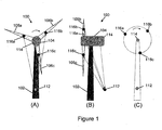
- Figure 1 illustrates an exemplary wind turbine 100 with a single level hierarchy condition monitoring system.
- Figure 1(A) provides a front view of the wind turbine 100
- Figure 1(B) provides a side view of the wind turbine 100
- Figure 1(C) provides a simplified front view showing the communication nodes and an outline of the structure of the wind turbine 100.
- the wind turbine 100 includes a tower 102, a gearbox 104 and a plurality of wind turbine blades 106.
- the exemplary wind turbine 100 can include any number of two or more turbine blades 106. Three turbine blades 106a, 106b, 106c are shown for illustration in Figure 1 .
- the wind turbine 100 also includes a controller 112, a hub node 114 and a plurality of blade sensors 116, with at least one blade sensor 116 per blade 106.
- the controller 112 may or may not be located on the wind turbine 100.
- the hub node 114 is coupled to the gearbox 104, and the blade sensors 116a, 116b, 116c are coupled to the wind turbine blades 106a, 106b, 106c, respectively.
- the controller 112 has direct bidirectional communication with the hub node 114 and each of the blade sensors 116.
- Various communication protocols using wired and wireless communication links can be used to link the communication nodes 112, 114, 116.
- An exemplary communication protocol is to use wireless communication between the controller 112, the hub node 114 and the blade sensors 116.
- An alternative communication protocol is to use wired communication between the controller 112 and the hub node 114, and to use wireless communication between the blade sensors 116 and the controller 112 and/or hub node 114.
- the controller 112 can run applications, detect and process readings from the blade sensors 116 and the hub node 114 as required by the applications, and then communicate instructions to the hub node 114 and/or blade sensors 116 to take appropriate actions such as stopping the rotor, increasing/decreasing the blade rotation speed, changing blade angles etc.
- Figure 2 illustrates an alternative exemplary wind turbine 200 with a two level hierarchy condition monitoring system.
- Figure 2(A) provides a front view of the wind turbine 200
- Figure 2(B) provides a side view of the wind turbine 200
- Figure 2(C) provides a simplified front view showing the communication nodes and an outline of the structure of the wind turbine 200.
- the wind turbine 200 also includes a tower 102, a gearbox 104 and a plurality of wind blades 106.
- the communication nodes of the wind turbine 200 are linked differently than the communication nodes of the wind turbine 100.
- the wind turbine 200 includes a controller 212, a hub node 214 and a plurality of blade sensors 216, with at least one blade sensor 216 per blade 106.
- the controller 212 may or may not be located on the wind turbine 200.
- the hub node 214 is coupled to the gearbox 104, and the blade sensors 216a, 216b, 216c are coupled to the wind turbine blades 106a, 106b, 106c, respectively.
- the controller 212 has direct bidirectional communication with the hub node 214, and the hub node 214 has direct bidirectional communication with each of the blade sensors 216. However, the controller 212 does not have direct bidirectional communication with the blade sensors 216.
- Various communication protocols using wired and wireless communication links can be used to link the communication nodes 212, 214, 216.
- An exemplary communication protocol is to use wireless communication between the controller 212 and the hub node 214, and to use wireless communication between the hub node 214 and the blade sensors 216.
- An alternative communication protocol is to use wired communication between the controller 212 and the hub node 214, and to use wireless communication between the hub node 214 and the blade sensors 216.
- the controller 212 can run applications and the hub node 214 can receive readings from the blade sensors 216, the controller 212 can receive readings from the hub node 214 and from the blade sensors 216 through the hub node 214 as required by the applications, the controller 212 can communicate instructions to the hub node 214 to take appropriate actions, and the hub node 214 can forward instructions to the blade sensors 216 as necessary.
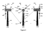
- Figure 3 illustrates an alternative exemplary wind turbine 300 with a two level hierarchy condition monitoring system in which a single controller is used for multiple wind turbines 300.
- Figure 3 shows an exemplary system with three wind turbines 300 linked to a single controller 312, but more or less than three wind turbines 300 can be linked to the controller 312.
- Each wind turbine 300 includes a tower 102, a gearbox 104 and a plurality of wind turbine blades 106.
- the communication nodes of the wind turbine 300 are linked differently such that a single controller 312 is used for multiple wind turbines 300.
- the condition monitoring system shown in Figure 3 includes a single controller 312 linked to a plurality of wind turbines, a hub node 314 coupled to each of the wind turbines 300 of the plurality of wind turbines, and at least one blade sensor 316 coupled to each of the wind turbine blades 106 of the plurality of wind turbines.
- the controller 312 may or may not be located on one of the plurality of wind turbines.
- a hub node 314 is coupled to the gearbox 104 of each of the wind turbines 300, and blade sensors 316a, 316b, 316c are coupled to the wind turbine blades 106a, 106b, 106c, respectively, of each of the wind turbines 300.
- the controller 312 has direct bidirectional commumcation with the hub node 314 of each wind turbine 300 of the plurality of wind turbines, and for each wind turbine 300 the hub node 314 has direct bidirectional communication with each of the blade sensors 316 of that wind turbine 300.
- the controller 312 does not have direct bidirectional communication with the blade sensors 316.
- Various communication protocols using wired and wireless communication links can be used to link the communication nodes 312, 314, 316.
- An exemplary communication protocol is to use wireless communication between the controller 312 and each of the linked hub nodes 314, and for each of the wind turbines 300 to use wireless communication between the hub node 314 and the blade sensors 316 of that wind turbine 300.
- An alternative communication protocol is to use wired communication between the controller 312 and each of the linked hub nodes 314, and for each of the wind turbines 300 to use wireless communication between the hub node 314 and the blade sensors 316 of that wind turbine 300.
- the controller 312 can run applications and the hub nodes 314 can receive readings from the blade sensors 316, the controller 312 can receive readings from the hub nodes 314 and from the blade sensors 316 through the hub nodes 314 as required by the applications, the controller 312 can communicate instructions to the appropriate hub nodes 314 to take appropriate actions, and the hub nodes 314 can forward instructions to the blade sensors 316 as necessary.
- Figure 4 illustrates an alternative exemplary wind turbine 400 with a single level hierarchy condition monitoring system in which a single controller is used for multiple wind turbines 400.
- Figure 4 shows an exemplary system with three wind turbines 400 linked to a single controller 412, but more or less than three wind turbines 400 can be linked to the controller 412.
- Each wind turbine 400 includes a tower 102, a gearbox 104 and a plurality of wind turbine blades 106.
- the communication nodes of the wind turbine 400 are linked differently such that a single controller 412 is used for multiple wind turbines 400.
- the condition monitoring system shown in Figure 4 includes a single controller 412 linked to the plurality of hub nodes 414 and blade sensors 416 of the plurality of wind turbines 400.
- the controller 412 may or may not be located on one of the wind turbines 400.
- a hub node 414 is coupled to the gearbox 104 of each of the wind turbines 400, and blade sensors 416a, 416b, 416c are coupled to the wind turbine blades 106a, 106b, 106c, respectively, of each of the wind turbines 400.
- the controller 412 has direct bidirectional communication with the hub nodes 414 and the blade sensors 416 of each of the wind turbines 400 of the plurality of wind turbines.
- Various communication protocols using wired and wireless communication links can be used to link the communication nodes 412, 414, 416.
- An exemplary communication protocol is to use wireless communication between the controller 412 and each of the linked hub nodes 414 and turbine blade sensors 416 of the plurality of wind turbines.
- An alternative communication protocol is to use wired communication between the controller 412 and the linked hub nodes 414 of the plurality of wind turbines, and to use wireless communication between the controller 412 and the linked blade sensors 416 of the plurality of wind turbines.
- the controller 412 can run applications, detect and process readings from the blade sensors 416 and the hub nodes 414 as required by the applications, and the controller 412 can communicate instructions to the hub nodes 414 and/or blade sensors 416 to take appropriate actions such as stopping the rotor, increasing/decreasing the blade rotation speed, changing blade angles, etc.
- a multi-axis accelerometer sensor can be used in a condition monitoring system for robust wireless communication.
- a multi-axis accelerometer sensor can sense vibrations and movement in the wind turbine blades and other components of the wind turbine.
- a multi-axis accelerometer sensor can be used to sense orientation and acceleration of a wind turbine blade which can be used to identify the current and future position of the blade or gearbox. This position information can be used for various applications, for example position information can be used to avoid shadowing, to select desired communication positions, to develop communication scheduling algorithms and/or to develop power efficient communication algorithms.
- Shadowing occurs when obstacles obstruct the direct wireless communication path between a pair of nodes.
- Position information can be provided by a multi-axis accelerometer sensor to avoid shadowing effects on communication.
- a direct communication path between a pair of nodes can be obstructed and thereby be affected by shadowing.
- Some exemplary shadowing scenarios are illustrated in Figures 5 , 6 and 7 . Many other shadowing scenarios are possible, and are different depending on the locations of the communication nodes.
- Position information can be used to determine blade and gearbox positions that are affected by shadowing for direct communication, such as the exemplary positions shown in Figures 5 , 6 and 7 , and these positions can be avoided when developing communication schedules.
- Figure 5 illustrates an exemplary shadowing scenario for a two level hierarchy condition monitoring system using the exemplary wind turbine 200 of Figure 2 .
- Figure 5(A) illustrates a front view of the shadowing scenario
- Figure 5(B) illustrates a side view of the shadowing scenario
- Figure 5(C) illustrates a simplified front view of the shadowing scenario which shows the communication nodes and an outline of the structure of the wind turbine 200.
- the controller 212 has direct bidirectional communication with the hub node 214
- the hub node 214 has direct bidirectional communication with each of the blade sensors 216.
- FIG. 5 specifically shows the scenario when the turbine blade 106c passes in front of the tower 102 such that the tower 102 obstructs the direct wireless communication path between the hub node 214 and the sensor 216c of the turbine blade 106c.
- a shadowing area 500 is shown in Figures 5(B) and 5(C) . Note that this area occurs for each of the turbine blade sensors 216a, 216b, 216c as its respective turbine blade 106a, 106b, 106c passes in front of the tower 102 during a rotation.
- Figure 6 illustrates exemplary shadowing scenarios for a single level hierarchy condition monitoring system using the exemplary wind turbine 100 of Figure 1 .
- Figure 6(A) illustrates a front view of the shadowing scenarios
- Figure 6(B) illustrates a side view of the shadowing scenarios
- Figure 6(C) illustrates a simplified front view of the shadowing scenarios which shows the communication nodes and an outline of the structure of the wind turbine 100.
- the controller 112 has direct bidirectional communication with the hub node 114 and each of the blade sensors 116.
- the controller node 112 is behind the wind turbine 100, meaning on the opposite side of the tower 102 as the blades 106.
- each of the turbine blades 106 will pass through two shadowing areas.
- a first shadowing area 600 occurs when a turbine blade 106 passes in front of the tower 102 such that the tower 102 obstructs the direct wireless communication path between the controller 112 and the sensor 116 of the turbine blade 106 passing in front of the tower 102.
- a second shadowing area 602 occurs around the top of rotation where a sensor 116 of a turbine blade 106 near the top of rotation passes above the gearbox 104 such that the gearbox 104 obstructs the direct wireless communication path between the controller 112 and the sensor 116.
- Figure 6(B) illustrates the scenarios when the turbine blade 106c passes in front of the tower 102 such that the tower 102 obstructs the direct wireless communication path between the controller 112 and the sensor 116c of the turbine blade 106c (first shadowing area 600); and when the sensor 116b of the turbine blade 106b near the top of rotation passes above the gearbox 104 such that the gearbox 104 obstructs the direct wireless communication path between the controller 112 and the sensor 116b (second shadowing area 602). Shadowing areas 600 and 602 are shown in Figures 6(B) and 6(C) . Note that these shadowing areas occur for each of the turbine blade sensors 116a, 116b, 116c as its respective turbine blade 106a, 106b, 106c passes through the shadowing areas 600 and 602 during a rotation.
- Figure 7 illustrates an exemplary shadowing scenario for a single level hierarchy condition monitoring system using the exemplary wind turbine 100 of Figure 1 .
- Figure 7(A) illustrates a front view of the shadowing scenario
- Figure 7(B) illustrates a side view of the shadowing scenario
- Figure 7(C) illustrates a simplified front view of the shadowing scenario which shows the communication nodes and an outline of the structure of the wind turbine 100.
- the controller 112 has direct bidirectional communication with the hub node 114 and each of the blade sensors 116.
- the controller node 112 is in front of the wind turbine 100, meaning on the same side of the tower 102 as the blades 106.
- a first shadowing area 700 affecting the hub node 114 to controller 112 communication path occurs as the wind turbine gearbox 104 oscillates on the tower 102.
- the tower 102 obstructs the direct wireless communication path between the controller 112 and the hub node 114.
- a second shadowing area 702 occurs as the wind turbine blades 106a, 106b, 106c rotate about an axis passing through the gearbox 104, and each of the blades 106 passes through the second shadowing area 702 near the top of rotation where the front of the gearbox 104 (the portion of the gearbox 104 on the opposite side of the blades 106 as the tower 102) obstructs the direct wireless communication path between the turbine blade 106 and the controller 112.
- shadowing areas 700, 702 will be affected by various factors, for example where the controller 112 is located relative to the tower 102, where the hub node 114 is coupled to the gearbox 104, where the sensors 116 are located on the blades 106 and how far the front of the gearbox 104 extends in front of the blades 106.
- Figure 7 specifically shows the scenario where the hub node 114 is attached to the gearbox 104 behind the tower 102 and the controller 112 is located in front of the tower 102 such that the tower 102 obstructs the direct wireless communication path between the controller 112 and the hub node 114 causing the first shadowing area 700; and where the blade sensor 116a coupled to the turbine blade 106a is around the peak of rotation such that the front of the gearbox 104 obstructs the direct wireless communication path between the controller 112 and the blade sensor 116a causing the second shadowing area 702.
- the shadowing areas 700, 702 are indicated in Figures 7(B) and 7(C) .
- the first shadowing area 700 is also applicable to a two level hierarchy condition monitoring system since it affects the communication path between the controller 112, 212 and the hub node 114, 214.
- the hub node 114 can include a multi-axis accelerometer or other capable sensor that can be used to provide position information for the hub node 114.
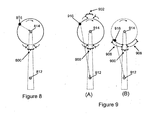
- Position information such as the information that can be provided by a multi-axis accelerometer sensor, can also be used for determination of desired communication positions. Again depending on the network architecture, there will be some controller, gearbox and blade locations more suitable for communication. Various factors can select the desired communication positions including shadowing. Wireless communication quality decreases as the distance between communication nodes increases. This can also be used to make communication more energy efficient, for example higher data rates can be achieved at closer distances which can reduce power consumption for transmission. The number of desired communication positions, for example size of the blade arc for desired communications, may depend on communication range constraints. Figures 8 and 9 indicate favorable positions for blade sensors for communication with a hub node and a controller.
- Figure 8 illustrates favorable blade locations for communication between blade sensors 816 and a hub node 814 coupled to a gearbox.
- Figure 8 only shows one blade sensor 816 but it should be understood that there would be a plurality of blade sensors 816 coupled to a plurality of blades rotating around the wind turbine gearbox.
- the distance between the blade sensor nodes 816 and the hub node 814 is substantially equal as the blades rotate around the gearbox.
- the desired communication positions for a blade sensor 816 for communication with the hub node 814 are unaffected by rotation position except for the shadowing area 800.
- Figure 9 illustrates favorable blade locations for communication between blade sensors 916 and a controller node 912.
- Figures 9(A) and 9(B) only show one blade sensor 916 but it should be understood that there would be a plurality of blade sensors 916 coupled to a plurality of blades rotating around the wind turbine gearbox.
- Figure 9(A) only shadowing is taken into account to determine desired communication positions.
- the tower In a first shadowing area 900, the tower obstructs the direct communication path between the blade sensor 916 and the controller 912.
- the gearbox obstructs the direct communication path between the blade sensor 916 and the controller 912. Obviously the extent of the obstruction will depend on the relative locations of the blade sensors, the controller, the tower and the gearbox.
- both shadowing and communication distance are taken into account to determine desired communication positions. Since the controller 912 is located below the blade sensors 916, the blade sensor positions near the bottom of rotation in areas 906 and 908 where the blade sensors 916 are nearer to the controller 912 but not obstructed by the tower shadowing area 900 will be better for wireless communication since the communication path distance is shorter. The closer distance may provide better communication reliability and efficiency.
- the next step is to develop communication schedules so that each of the sensor nodes can communicate with the controller and/or hub node reliably without interfering with the communications of other sensor nodes.
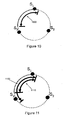
- a sensor node can start transmitting when its blade enters the favorable communication region and can continue to communicate while its blade remains within the favorable communication region. This is possible when the favorable communication region is less than 1/n of the total locations, where 'n' is the total number of blades. In that case no two blades (or sensors) will be in the favorable communication region simultaneously and the transmission region is equal to the favorable communication region.
- Figure 10 shows such a scenario where the favorable communication region 1000 is less than one-third of total blade locations and there are three or fewer blades. In this scenario, the transmission region can be the entire favorable communication region 1000 for each blade sensor.
- Figure 11 shows the scenario where the favorable communication region 1100 is greater than or equal to one-third of total blade locations and there are three blades. In this scenario, before one blade completely leaves the favorable communication region 1100 the next blade enters the favorable communication region 1100. Thus, as shown in Figure 11 , blade sensors Si and S3 might transmit simultaneously and thereby interfere with each others communication.
- a communication scheduling algorithm can be implemented to ensure that sensors transmit only during a subset of the favorable communication region, such as a transmission region 1110.
- the transmission region 1110 is a reduced region such that it is less than one-third of the overall sensor locations and only one sensor is in the transmission region 1110 at a time.
- the position information can also be used to develop power efficient transmission procedures.
- the transmission power required to achieve a desired reliability is directly proportional to the distance of separation between the transmitting and receiving devices. Therefore, of all the available favorable communication locations, the locations that have less separation distance between the transmitter and receiver can be selected for improved power efficiency. Examples of this are the regions 906 and 908 of Figure 9(B) .
- a separation threshold can be established that enables the necessary communication between the nodes to take place but also reduces the separation distance between the communicating nodes to reduce the power requirements for the communication. This can save energy by transmitting at less power and still provide the desired reliability. Saving energy can be important, especially when wireless devices are battery powered. Hence, knowing blade location also enables factoring power efficiency into communication scheduling.
Landscapes
- Engineering & Computer Science (AREA)
- Life Sciences & Earth Sciences (AREA)
- Sustainable Development (AREA)
- Sustainable Energy (AREA)
- Chemical & Material Sciences (AREA)
- Combustion & Propulsion (AREA)
- Mechanical Engineering (AREA)
- General Engineering & Computer Science (AREA)
- Wind Motors (AREA)
- Arrangements For Transmission Of Measured Signals (AREA)
Description
- The present invention relates to a wind turbine condition monitoring system and method.
-
US 2010/021298 A1 discloses a wind turbine condition monitoring system for one or more wind turbines, each wind turbine comprising a tower, a gearbox coupled to the tower and a plurality of turbine blades coupled to the gearbox. The system comprises a plurality of blade sensors providing blade sensor readings, each of the plurality of blade sensors being coupled to one of the plurality of blades of the one or more wind turbines. A hub node is coupled to the gearbox of each of the one or more wind turbines, and a controller is provided in communication with one or more hub nodes and a plurality of blade sensors. The controller determines the position of each turbine blade of the plurality of turbine blades based on the blade sensor readings. - Harvesting wind energy using wind turbines to supply electrical power is an increasing market. The efficiency and lifespan of wind turbines is dependent upon the conditions of the wind turbines, so there are many applications that use sensors mounted on wind turbine blades for condition monitoring. Wind turbine blade condition monitoring systems typically use wired communication between the sensors attached to wind blades and the controller which may or may not be located on the wind turbine. The controller detects the wind blade sensor readings, runs the required algorithms based on the needs of the specific applications, and then communicates the decision to a hub node of the wind turbine to take appropriate actions such as stopping the rotor, increasing/decreasing the blade rotation speed, etc. It is envisioned that communication between the sensors and the hub/controller can be wireless while the communication between the hub node and controller can be wired or wireless. However, the wireless communication paths between the various communication nodes of a wind turbine condition monitoring system can periodically be obstructed by structures of the wind turbine. For example, the tower may obstruct communication between a sensor on a turbine blade and a controller.
- Condition monitoring of wind turbine blades can increase the lifetime of the blades and turbine by detecting abnormalities earlier and thereby enabling the taking of preventive actions earlier to avoid extensive damage to the blades and turbine. One of the various sensors that can be used for condition monitoring is an accelerometer sensor. Accelerometer sensors, when placed on an object, can be used to measure the vibration of that object. Accelerometers can also be used to determine the position of an object, for example the wind turbine blade positions.
- It would be desirable to detect the positions of the wind turbine blades and use the position information to develop robust wireless communication schedules between blade sensors, hub nodes and controllers that meet desired communication parameters. These desired communication parameters can include for example, avoiding path obstruction and multiple transmission interference, and achieving reliability and power efficiency measures.
- A wind turbine condition monitoring system for one or more wind turbines according to the invention is defined in independent claims 1 and 4, respectively. The blade sensors can include multi-axis accelerometers.
- The controller can be configured to only communicate with a particular hub node of the one or more hub nodes when the particular hub node is outside hub node shadowing areas. Direct wireless communication between the controller and the particular hub node being obstructed when the particular hub node is in the hub node shadowing areas.
- The controller can be configured to only communicate with a hub node when that hub node is outside hub node shadowing areas. Direct wireless communication between the controller and a hub node being obstructed when the hub node is in the hub node shadowing areas.
- The controller can be configured to only communicate with a particular blade sensor when the particular blade sensor is in a favorable communication region. The controller can determine whether a blade sensor is in the favorable communication region based on the blade sensor readings. The favorable communication region has an unobstructed communication path between the controller and the blade sensor. The favorable communication region can be further constrained such that the separation distance between the controller and the particular blade sensor is less than a separation threshold when the particular blade sensor is in the favorable communication region. The favorable communication region can also be further constrained such that only one blade sensor of the plurality of blade sensors is in the favorable communication region at a time.
- A wind turbine condition monitoring method for wind turbines with a monitoring system according to independent claim 10 is disclosed where each wind turbine includes a tower, a gearbox coupled to the tower, and a plurality of turbine blades coupled to the gearbox, and the monitoring system includes a controller, a hub node coupled to each gearbox, and a plurality of blade sensors. The condition monitoring method includes determining shadowing areas, configuring each of the plurality of blade sensors to only transmit when outside the shadowing areas, receiving blade sensor readings at the controller from a blade sensor when the blade sensor is outside the shadowing areas, and determining a position of the blade sensor based on the blade sensor readings. The direct communication path between a blade sensor and the controller is obstructed when the blade sensor is in the shadowing areas. The method can also include determining favorable communication regions, configuring each of the plurality of blade sensors to only transmit when within the favorable communication regions; and receiving blade sensor readings at the controller from a blade sensor when the blade sensor is within the favorable communication regions. The favorable communication regions are areas outside the shadowing areas where the communication path between the blade sensor and the controller is less than a separation threshold. The method can also include determining a transmission region outside the shadowing areas or within the favorable communication regions such that only one blade sensor of the plurality of blade sensors is in the transmission region at a time; configuring the blade sensors to only transmit when within the transmission region, and receiving blade sensor readings at the controller from a blade sensor when the blade sensor is within the transmission region.
- A wind turbine condition monitoring method for wind turbines with a monitoring system according to the independent claim 14 is disclosed where each wind turbine includes a tower, a gearbox coupled to the tower, and a plurality of turbine blades coupled to the gearbox, and the monitoring system includes a controller, a hub node coupled to each gearbox, and a plurality of blade sensors. The condition monitoring method includes determining blade shadowing areas, configuring each of the plurality of blade sensors to only transmit when outside the blade shadowing areas, receiving blade sensor readings at the hub node from a blade sensor when the blade sensor is outside the blade shadowing areas; transmitting hub node signals from the hub node to the controller, and determining a position of the blade sensor based on the blade sensor readings. The hub node signals include information from the blade sensor readings. The communication path between a blade sensor and the hub node is obstructed when the blade sensor is in the blade shadowing areas. The method can also include determining hub shadowing areas, determining a position of the hub node based on the hub node signals, configuring the hub node to only transmit to the controller when outside the hub shadowing areas, and configuring the controller to only transmit to the hub node when the hub node is outside the hub shadowing areas. The communication path between the hub node and the controller is obstructed when the hub node is in the hub shadowing areas.
- The above mentioned and other features and objects of this invention, and the manner of attaining them, will become more apparent and the invention itself will be better understood by reference to the following description of exemplary embodiments of the invention taken in conjunction with the accompanying drawings, wherein:
-
FIG. 1 illustrates an exemplary wind turbine with a single level hierarchy condition monitoring system; -
FIG. 2 illustrates an exemplary wind turbine with a two level hierarchy condition monitoring system; -
FIG. 3 illustrates an exemplary wind turbine with a two level hierarchy condition monitoring system in which a single controller is used to control multiple wind turbines; -
FIG. 4 illustrates an exemplary wind turbine with a single level hierarchy condition monitoring system in which a single controller is used to control multiple wind turbines; -
FIG. 5 illustrates an exemplary shadowing scenario between blade sensors and a hub node for a wind turbine with a two level hierarchy condition monitoring system; -
FIG. 6 illustrates exemplary shadowing scenarios between blade sensors and a hub node and between blade sensors and a controller for a wind turbine with a single level hierarchy condition monitoring system; -
FIG. 7 illustrates exemplary shadowing scenarios between blade sensors and a controller and between a hub node and a controller for a wind turbine with a single level hierarchy condition monitoring system; -
FIG. 8 illustrates favorable blade locations for communication between blade sensors and a hub node coupled to a gearbox; -
FIG. 9 illustrates favorable blade locations for communication between blade sensors and a controller node; -
FIG. 10 illustrates an exemplary scenario where a blade sensor can transmit during any part of a favorable communication region without interfering with other blade sensors; and -
FIG. 11 illustrates an exemplary scenario where a blade sensor can transmit only during a portion of a favorable communication region without interfering with other blade sensors. - Corresponding reference characters indicate corresponding parts throughout the several views. Although the exemplification set out herein illustrates embodiments of the invention, in several forms, the embodiments disclosed below are not intended to be exhaustive or to be construed as limiting the scope of the invention to the precise forms disclosed.
- There are numerous applications that use sensors mounted on wind turbines and wind turbine blades for condition monitoring, for example to detect damage or potential damage to the wind turbine and/or the blades, or to increase the energy harvesting efficiency of the wind turbine. Condition monitoring of wind turbine blades can increase the lifetime of the blades and turbine by detecting abnormalities earlier and thereby enabling the taking of preventive measures sooner to avoid or reduce damage to the blades and turbine. An exemplary type of sensor that can be used for wind turbine condition monitoring is an accelerometer which can measure acceleration of an object. An accelerometer can help in detecting lightning strikes on a wind turbine blade so that the wind turbine (also referred to as a windmill) can be stopped quickly after any lightning strike to reduce damage to the turbine and the blades. Accelerometer sensor data can also be used to detect ice deposits on the turbine blades to enable stopping of the turbine blades at an appropriate level of ice deposits and restarting the turbine blades when sufficient ice has melted.
- The data from wind turbine condition monitoring sensors can be collected at a central unit or controller which may be located on the wind turbine tower or away from the wind turbine tower. The central unit can collect the sensor data and execute algorithms based on the needs of the specific application. The wind turbine sensors can be wireless and data from the sensors can be transmitted to the central unit on wireless links. Techniques can be implemented to make the wireless data transmission robust and energy efficient. Accelerometer sensors can be used to determine the position of wind turbine blades, and this position information can be used to determine transmission times when the wireless links between the sensors and the central unit are within acceptable limits and to determine scheduling for the transmissions of data from multiple sensors on different blades to the central unit or intermediate communication node.
-
Figure 1 illustrates anexemplary wind turbine 100 with a single level hierarchy condition monitoring system.Figure 1(A) provides a front view of thewind turbine 100,Figure 1(B) provides a side view of thewind turbine 100, andFigure 1(C) provides a simplified front view showing the communication nodes and an outline of the structure of thewind turbine 100. Thewind turbine 100 includes atower 102, agearbox 104 and a plurality of wind turbine blades 106. Theexemplary wind turbine 100 can include any number of two or more turbine blades 106. Threeturbine blades Figure 1 . Thewind turbine 100 also includes acontroller 112, ahub node 114 and a plurality of blade sensors 116, with at least one blade sensor 116 per blade 106. Thecontroller 112 may or may not be located on thewind turbine 100. In thisexemplary wind turbine 100, thehub node 114 is coupled to thegearbox 104, and theblade sensors wind turbine blades - In the single level hierarchy condition monitoring system embodiment shown in
Figure 1 , thecontroller 112 has direct bidirectional communication with thehub node 114 and each of the blade sensors 116. Various communication protocols using wired and wireless communication links can be used to link thecommunication nodes controller 112, thehub node 114 and the blade sensors 116. An alternative communication protocol is to use wired communication between thecontroller 112 and thehub node 114, and to use wireless communication between the blade sensors 116 and thecontroller 112 and/orhub node 114. Thecontroller 112 can run applications, detect and process readings from the blade sensors 116 and thehub node 114 as required by the applications, and then communicate instructions to thehub node 114 and/or blade sensors 116 to take appropriate actions such as stopping the rotor, increasing/decreasing the blade rotation speed, changing blade angles etc. -
Figure 2 illustrates an alternativeexemplary wind turbine 200 with a two level hierarchy condition monitoring system.Figure 2(A) provides a front view of thewind turbine 200,Figure 2(B) provides a side view of thewind turbine 200, andFigure 2(C) provides a simplified front view showing the communication nodes and an outline of the structure of thewind turbine 200. Thewind turbine 200 also includes atower 102, agearbox 104 and a plurality of wind blades 106. However, the communication nodes of thewind turbine 200 are linked differently than the communication nodes of thewind turbine 100. Thewind turbine 200 includes acontroller 212, ahub node 214 and a plurality of blade sensors 216, with at least one blade sensor 216 per blade 106. Thecontroller 212 may or may not be located on thewind turbine 200. In thisexemplary embodiment 200, thehub node 214 is coupled to thegearbox 104, and theblade sensors wind turbine blades - In the two level hierarchy condition monitoring system shown in
Figure 2 , thecontroller 212 has direct bidirectional communication with thehub node 214, and thehub node 214 has direct bidirectional communication with each of the blade sensors 216. However, thecontroller 212 does not have direct bidirectional communication with the blade sensors 216. Various communication protocols using wired and wireless communication links can be used to link thecommunication nodes controller 212 and thehub node 214, and to use wireless communication between thehub node 214 and the blade sensors 216. An alternative communication protocol is to use wired communication between thecontroller 212 and thehub node 214, and to use wireless communication between thehub node 214 and the blade sensors 216. Thecontroller 212 can run applications and thehub node 214 can receive readings from the blade sensors 216, thecontroller 212 can receive readings from thehub node 214 and from the blade sensors 216 through thehub node 214 as required by the applications, thecontroller 212 can communicate instructions to thehub node 214 to take appropriate actions, and thehub node 214 can forward instructions to the blade sensors 216 as necessary. -
Figure 3 illustrates an alternativeexemplary wind turbine 300 with a two level hierarchy condition monitoring system in which a single controller is used formultiple wind turbines 300.Figure 3 shows an exemplary system with threewind turbines 300 linked to asingle controller 312, but more or less than threewind turbines 300 can be linked to thecontroller 312. Eachwind turbine 300 includes atower 102, agearbox 104 and a plurality of wind turbine blades 106. However, the communication nodes of thewind turbine 300 are linked differently such that asingle controller 312 is used formultiple wind turbines 300. The condition monitoring system shown inFigure 3 includes asingle controller 312 linked to a plurality of wind turbines, ahub node 314 coupled to each of thewind turbines 300 of the plurality of wind turbines, and at least one blade sensor 316 coupled to each of the wind turbine blades 106 of the plurality of wind turbines. Thecontroller 312 may or may not be located on one of the plurality of wind turbines. In this exemplary embodiment, ahub node 314 is coupled to thegearbox 104 of each of thewind turbines 300, andblade sensors wind turbine blades wind turbines 300. - In the two level hierarchy condition monitoring system embodiment shown in
Figure 3 , thecontroller 312 has direct bidirectional commumcation with thehub node 314 of eachwind turbine 300 of the plurality of wind turbines, and for eachwind turbine 300 thehub node 314 has direct bidirectional communication with each of the blade sensors 316 of thatwind turbine 300. However, thecontroller 312 does not have direct bidirectional communication with the blade sensors 316. Various communication protocols using wired and wireless communication links can be used to link thecommunication nodes controller 312 and each of the linkedhub nodes 314, and for each of thewind turbines 300 to use wireless communication between thehub node 314 and the blade sensors 316 of thatwind turbine 300. An alternative communication protocol is to use wired communication between thecontroller 312 and each of the linkedhub nodes 314, and for each of thewind turbines 300 to use wireless communication between thehub node 314 and the blade sensors 316 of thatwind turbine 300. Thecontroller 312 can run applications and thehub nodes 314 can receive readings from the blade sensors 316, thecontroller 312 can receive readings from thehub nodes 314 and from the blade sensors 316 through thehub nodes 314 as required by the applications, thecontroller 312 can communicate instructions to theappropriate hub nodes 314 to take appropriate actions, and thehub nodes 314 can forward instructions to the blade sensors 316 as necessary. -
Figure 4 illustrates an alternativeexemplary wind turbine 400 with a single level hierarchy condition monitoring system in which a single controller is used formultiple wind turbines 400.Figure 4 shows an exemplary system with threewind turbines 400 linked to asingle controller 412, but more or less than threewind turbines 400 can be linked to thecontroller 412. Eachwind turbine 400 includes atower 102, agearbox 104 and a plurality of wind turbine blades 106. However, the communication nodes of thewind turbine 400 are linked differently such that asingle controller 412 is used formultiple wind turbines 400. The condition monitoring system shown inFigure 4 includes asingle controller 412 linked to the plurality ofhub nodes 414 and blade sensors 416 of the plurality ofwind turbines 400. Thecontroller 412 may or may not be located on one of thewind turbines 400. In thisexemplary embodiment 400, ahub node 414 is coupled to thegearbox 104 of each of thewind turbines 400, andblade sensors wind turbine blades wind turbines 400. - In the single level hierarchy condition monitoring system embodiment shown in
Figure 4 , thecontroller 412 has direct bidirectional communication with thehub nodes 414 and the blade sensors 416 of each of thewind turbines 400 of the plurality of wind turbines. Various communication protocols using wired and wireless communication links can be used to link thecommunication nodes controller 412 and each of the linkedhub nodes 414 and turbine blade sensors 416 of the plurality of wind turbines. An alternative communication protocol is to use wired communication between thecontroller 412 and the linkedhub nodes 414 of the plurality of wind turbines, and to use wireless communication between thecontroller 412 and the linked blade sensors 416 of the plurality of wind turbines. Thecontroller 412 can run applications, detect and process readings from the blade sensors 416 and thehub nodes 414 as required by the applications, and thecontroller 412 can communicate instructions to thehub nodes 414 and/or blade sensors 416 to take appropriate actions such as stopping the rotor, increasing/decreasing the blade rotation speed, changing blade angles, etc. - A multi-axis accelerometer sensor can be used in a condition monitoring system for robust wireless communication. A multi-axis accelerometer sensor can sense vibrations and movement in the wind turbine blades and other components of the wind turbine. A multi-axis accelerometer sensor can be used to sense orientation and acceleration of a wind turbine blade which can be used to identify the current and future position of the blade or gearbox. This position information can be used for various applications, for example position information can be used to avoid shadowing, to select desired communication positions, to develop communication scheduling algorithms and/or to develop power efficient communication algorithms.
- Shadowing occurs when obstacles obstruct the direct wireless communication path between a pair of nodes. Position information can be provided by a multi-axis accelerometer sensor to avoid shadowing effects on communication. Depending on the positions of the
tower 102, thegearbox 104 and the blades 106 and the network architecture, several scenarios are possible where a direct communication path between a pair of nodes can be obstructed and thereby be affected by shadowing. Some exemplary shadowing scenarios are illustrated inFigures 5 ,6 and7 . Many other shadowing scenarios are possible, and are different depending on the locations of the communication nodes. Position information can be used to determine blade and gearbox positions that are affected by shadowing for direct communication, such as the exemplary positions shown inFigures 5 ,6 and7 , and these positions can be avoided when developing communication schedules. -
Figure 5 illustrates an exemplary shadowing scenario for a two level hierarchy condition monitoring system using theexemplary wind turbine 200 ofFigure 2 .Figure 5(A) illustrates a front view of the shadowing scenario,Figure 5(B) illustrates a side view of the shadowing scenario, andFigure 5(C) illustrates a simplified front view of the shadowing scenario which shows the communication nodes and an outline of the structure of thewind turbine 200. As described above for theexemplary wind turbine 200, thecontroller 212 has direct bidirectional communication with thehub node 214, and thehub node 214 has direct bidirectional communication with each of the blade sensors 216. In the shadowing scenario illustrated inFigure 5 , thewind turbine blades gearbox 104, and during a rotation each of the turbine blades 106 will pass in front of thetower 102 such that thetower 102 obstructs the direct wireless communication path between thehub node 214 and the sensor 216 of the turbine blade 106 passing in front of thetower 102.Figure 5 specifically shows the scenario when theturbine blade 106c passes in front of thetower 102 such that thetower 102 obstructs the direct wireless communication path between thehub node 214 and thesensor 216c of theturbine blade 106c. A shadowingarea 500 is shown inFigures 5(B) and 5(C) . Note that this area occurs for each of theturbine blade sensors respective turbine blade tower 102 during a rotation. -
Figure 6 illustrates exemplary shadowing scenarios for a single level hierarchy condition monitoring system using theexemplary wind turbine 100 ofFigure 1 .Figure 6(A) illustrates a front view of the shadowing scenarios,Figure 6(B) illustrates a side view of the shadowing scenarios, andFigure 6(C) illustrates a simplified front view of the shadowing scenarios which shows the communication nodes and an outline of the structure of thewind turbine 100. As described above for theexemplary wind turbine 100, thecontroller 112 has direct bidirectional communication with thehub node 114 and each of the blade sensors 116. In the shadowing scenario illustrated inFigure 6 , thecontroller node 112 is behind thewind turbine 100, meaning on the opposite side of thetower 102 as the blades 106. In this exemplary embodiment, as thewind turbine blades gearbox 104, each of the turbine blades 106 will pass through two shadowing areas. Afirst shadowing area 600 occurs when a turbine blade 106 passes in front of thetower 102 such that thetower 102 obstructs the direct wireless communication path between thecontroller 112 and the sensor 116 of the turbine blade 106 passing in front of thetower 102. Asecond shadowing area 602 occurs around the top of rotation where a sensor 116 of a turbine blade 106 near the top of rotation passes above thegearbox 104 such that thegearbox 104 obstructs the direct wireless communication path between thecontroller 112 and the sensor 116.Figure 6(B) illustrates the scenarios when theturbine blade 106c passes in front of thetower 102 such that thetower 102 obstructs the direct wireless communication path between thecontroller 112 and thesensor 116c of theturbine blade 106c (first shadowing area 600); and when thesensor 116b of theturbine blade 106b near the top of rotation passes above thegearbox 104 such that thegearbox 104 obstructs the direct wireless communication path between thecontroller 112 and thesensor 116b (second shadowing area 602). Shadowingareas Figures 6(B) and 6(C) . Note that these shadowing areas occur for each of theturbine blade sensors respective turbine blade areas -
Figure 7 illustrates an exemplary shadowing scenario for a single level hierarchy condition monitoring system using theexemplary wind turbine 100 ofFigure 1 .Figure 7(A) illustrates a front view of the shadowing scenario,Figure 7(B) illustrates a side view of the shadowing scenario, andFigure 7(C) illustrates a simplified front view of the shadowing scenario which shows the communication nodes and an outline of the structure of thewind turbine 100. As described above for theexemplary wind turbine 100, thecontroller 112 has direct bidirectional communication with thehub node 114 and each of the blade sensors 116. In the shadowing scenarios illustrated inFigure 7 , thecontroller node 112 is in front of thewind turbine 100, meaning on the same side of thetower 102 as the blades 106. Afirst shadowing area 700 affecting thehub node 114 tocontroller 112 communication path occurs as thewind turbine gearbox 104 oscillates on thetower 102. As thehub node 114 coupled to thegearbox 104 passes behind thetower 102 through thefirst shadowing area 700, thetower 102 obstructs the direct wireless communication path between thecontroller 112 and thehub node 114. Asecond shadowing area 702 occurs as thewind turbine blades gearbox 104, and each of the blades 106 passes through thesecond shadowing area 702 near the top of rotation where the front of the gearbox 104 (the portion of thegearbox 104 on the opposite side of the blades 106 as the tower 102) obstructs the direct wireless communication path between the turbine blade 106 and thecontroller 112. Note that these shadowingareas controller 112 is located relative to thetower 102, where thehub node 114 is coupled to thegearbox 104, where the sensors 116 are located on the blades 106 and how far the front of thegearbox 104 extends in front of the blades 106.Figure 7 specifically shows the scenario where thehub node 114 is attached to thegearbox 104 behind thetower 102 and thecontroller 112 is located in front of thetower 102 such that thetower 102 obstructs the direct wireless communication path between thecontroller 112 and thehub node 114 causing thefirst shadowing area 700; and where theblade sensor 116a coupled to theturbine blade 106a is around the peak of rotation such that the front of thegearbox 104 obstructs the direct wireless communication path between thecontroller 112 and theblade sensor 116a causing thesecond shadowing area 702. The shadowingareas Figures 7(B) and 7(C) . Thefirst shadowing area 700 is also applicable to a two level hierarchy condition monitoring system since it affects the communication path between thecontroller hub node hub node 114 can include a multi-axis accelerometer or other capable sensor that can be used to provide position information for thehub node 114. - Position information, such as the information that can be provided by a multi-axis accelerometer sensor, can also be used for determination of desired communication positions. Again depending on the network architecture, there will be some controller, gearbox and blade locations more suitable for communication. Various factors can select the desired communication positions including shadowing. Wireless communication quality decreases as the distance between communication nodes increases. This can also be used to make communication more energy efficient, for example higher data rates can be achieved at closer distances which can reduce power consumption for transmission. The number of desired communication positions, for example size of the blade arc for desired communications, may depend on communication range constraints.
Figures 8 and 9 indicate favorable positions for blade sensors for communication with a hub node and a controller. -
Figure 8 illustrates favorable blade locations for communication betweenblade sensors 816 and ahub node 814 coupled to a gearbox. For clarityFigure 8 only shows oneblade sensor 816 but it should be understood that there would be a plurality ofblade sensors 816 coupled to a plurality of blades rotating around the wind turbine gearbox. The distance between theblade sensor nodes 816 and thehub node 814 is substantially equal as the blades rotate around the gearbox. Thus, the desired communication positions for ablade sensor 816 for communication with thehub node 814 are unaffected by rotation position except for theshadowing area 800. -
Figure 9 illustrates favorable blade locations for communication betweenblade sensors 916 and acontroller node 912. For clarityFigures 9(A) and 9(B) only show oneblade sensor 916 but it should be understood that there would be a plurality ofblade sensors 916 coupled to a plurality of blades rotating around the wind turbine gearbox. InFigure 9(A) only shadowing is taken into account to determine desired communication positions. In afirst shadowing area 900, the tower obstructs the direct communication path between theblade sensor 916 and thecontroller 912. In asecond shadowing area 902, the gearbox obstructs the direct communication path between theblade sensor 916 and thecontroller 912. Obviously the extent of the obstruction will depend on the relative locations of the blade sensors, the controller, the tower and the gearbox. InFigure 9(B) both shadowing and communication distance are taken into account to determine desired communication positions. Since thecontroller 912 is located below theblade sensors 916, the blade sensor positions near the bottom of rotation inareas blade sensors 916 are nearer to thecontroller 912 but not obstructed by thetower shadowing area 900 will be better for wireless communication since the communication path distance is shorter. The closer distance may provide better communication reliability and efficiency. - Once favorable communication locations have been identified, the next step is to develop communication schedules so that each of the sensor nodes can communicate with the controller and/or hub node reliably without interfering with the communications of other sensor nodes. Ideally, a sensor node can start transmitting when its blade enters the favorable communication region and can continue to communicate while its blade remains within the favorable communication region. This is possible when the favorable communication region is less than 1/n of the total locations, where 'n' is the total number of blades. In that case no two blades (or sensors) will be in the favorable communication region simultaneously and the transmission region is equal to the favorable communication region.
Figure 10 shows such a scenario where thefavorable communication region 1000 is less than one-third of total blade locations and there are three or fewer blades. In this scenario, the transmission region can be the entirefavorable communication region 1000 for each blade sensor. -
Figure 11 shows the scenario where thefavorable communication region 1100 is greater than or equal to one-third of total blade locations and there are three blades. In this scenario, before one blade completely leaves thefavorable communication region 1100 the next blade enters thefavorable communication region 1100. Thus, as shown inFigure 11 , blade sensors Si and S3 might transmit simultaneously and thereby interfere with each others communication. A communication scheduling algorithm can be implemented to ensure that sensors transmit only during a subset of the favorable communication region, such as atransmission region 1110. Thetransmission region 1110 is a reduced region such that it is less than one-third of the overall sensor locations and only one sensor is in thetransmission region 1110 at a time. - The position information can also be used to develop power efficient transmission procedures. The transmission power required to achieve a desired reliability is directly proportional to the distance of separation between the transmitting and receiving devices. Therefore, of all the available favorable communication locations, the locations that have less separation distance between the transmitter and receiver can be selected for improved power efficiency. Examples of this are the
regions Figure 9(B) . A separation threshold can be established that enables the necessary communication between the nodes to take place but also reduces the separation distance between the communicating nodes to reduce the power requirements for the communication. This can save energy by transmitting at less power and still provide the desired reliability. Saving energy can be important, especially when wireless devices are battery powered. Hence, knowing blade location also enables factoring power efficiency into communication scheduling. - Furthermore, the application describes the following embodiments:
- Embodiment 1. The wind turbine condition monitoring method of another embodiment, further comprising:
- determining a transmission region outside the shadowing areas such that only one blade sensor of the plurality of blade sensors is in the transmission region at a time;
- configuring each of the plurality of blade sensors to only transmit when within the transmission region; and
- receiving blade sensor readings at the controller from the particular blade sensor when the particular blade sensor is within the transmission region.
- Embodiment 2. A wind turbine condition monitoring method for wind turbines with a monitoring system, each wind turbine comprising a tower, a gearbox coupled to the tower, and a plurality of turbine blades coupled to the gearbox, and the monitoring system comprising a controller, a hub node coupled to each gearbox, and a plurality of blade sensors, the condition monitoring method comprising:
- determining blade shadowing areas where the communication path between one of the plurality of blade sensors and the hub node is obstructed when the one of the plurality of blade sensors is in the blade shadowing areas; each blade sensor being coupled to one of the plurality of turbine blades;
- configuring each of the plurality of blade sensors to only transmit when outside the blade shadowing areas;
- receiving blade sensor readings at the hub node from a particular blade sensor of the plurality of blade sensors when the particular blade sensor is outside the blade shadowing areas; transmitting hub node signals from the hub node to the controller, the hub node signals including information from the blade sensor readings; and
- determining a position of the particular blade sensor based on the blade sensor readings.
- Embodiment 3. The wind turbine condition monitoring method of another embodiment, further comprising:
- determining hub shadowing areas where the communication path between the hub node and the controller is obstructed when the hub node is in the hub shadowing areas;
- determining a position of the hub node based on the hub node signals;
- configuring the hub node to only transmit to the controller when outside the hub shadowing areas; and
- configuring the controller to only transmit to the hub node when the hub node is outside the hub shadowing areas.
- Embodiment 4. The wind turbine condition monitoring method of another embodiment, further comprising:
- determining a transmission region outside the blade shadowing areas such that only one blade sensor of the plurality of blade sensors is in the transmission region at a time;
- configuring each of the plurality of blade sensors to only transmit when within the transmission region; and
- receiving blade sensor readings at the hub node from the particular blade sensor when the particular blade sensor is within the transmission region.
- Embodiment 5. The wind turbine condition monitoring method of another embodiment, wherein each of the plurality of blade sensors and the hub node includes a multi-axis accelerometer.
Claims (15)
- A wind turbine condition monitoring system for one or more wind turbines (100; 400), each wind turbine comprising a tower (102), a gearbox (104) coupled to the tower (102) and a plurality of turbine blades (106 a - c) coupled to the gearbox (104), the condition monitoring system comprising:a plurality of blade sensors (116 a- c; 416 a - c) providing blade sensor readings, each of the plurality of blade sensors (116 a- c; 416 a - c) being coupled to one of the plurality of blades (106 a - c) of the one or more wind turbines;a hub node (114; 414) coupled to the gearbox (104) of each of the one or more wind turbines; anda controller (112; 412) in communication with the one or more hub nodes (114; 414) and the plurality of blade sensors (116 a- c; 416 a - c);wherein the controller (112; 412) is configured to determine the position of each turbine blade of the plurality of turbine blades based on the blade sensor readings;wherein the controller (112; 412) has direct wireless communication with the one or more hub nodes (114; 414) and with each of the plurality of blade sensors (116 a- c; 416 a - c); andthe controller (112; 412) is configured to only communicate with a particular blade sensor of the plurality of blade sensors when the particular blade sensor is outside blade shadowing areas, direct wireless communication between the controller (112; 412) and the particular blade sensor being obstructed when the particular blade sensor is in the blade shadowing areas.
- The wind turbine condition monitoring system of claim 1, wherein each of the plurality of blade sensors is a multi-axis accelerometer.
- The wind turbine condition monitoring system of claim 1, wherein the controller (112; 412) is configured to only communicate with a particular hub node of the one or more hub nodes (114; 414) when the particular hub node is outside hub node shadowing areas, direct wireless communication between the controller (112; 412) and the particular hub node being obstructed when the particular hub node is in the hub node shadowing areas.
- A wind turbine condition monitoring system for one or more wind turbines (200; 300), each wind turbine comprising a tower (102), a gearbox (104) coupled to the tower (102) and a plurality of turbine blades (106 a - c) coupled to the gearbox (104), the condition monitoring system comprising:a plurality of blade sensors (216 a - c; 316 a - c) providing blade sensor readings, each of the plurality of blade sensors (216 a - c; 316 a - c) being coupled to one of the plurality of blades (106 a - c) of the one or more wind turbines;a hub node (214; 314) coupled to the gearbox (104) of each of the one or more wind turbines; and a controller (213; 312) in communication with the one or more hub nodes (214; 314) and the plurality of blade sensors (216 a - c; 316 a - c);wherein the controller (212; 312) is configured to determine the position of each turbine blade of the plurality of turbine blades (106 a- c) based on the blade sensor readings; wherein the controller (212; 312) has direct wireless communication with the one or more hub nodes (214; 314), and for each particular wind turbine of the one or more wind turbines the hub node (214; 314) of the particular wind turbine has direct wireless communication with each of the plurality of blade sensors (216 a - c; 316 a - c) coupled to the blades (106 a - c) of the particular wind turbine, the controller (212; 312) receiving the blade sensor readings from the plurality of blade sensors (216 a - c; 316 a - c) through the one or more hub nodes (214; 314); andwherein for each particular wind turbine of the plurality of wind turbines, the hub node (214; 314) of the particular wind turbine is configured to only communicate with a particular blade sensor of the plurality of blade sensors (216 a - c; 316 a - c) of the particular wind turbine when the particular blade sensor is not in blade shadowing areas, direct wireless communication between the hub node (214; 314) of the particular wind turbine and the particular blade sensor being obstructed when the particular blade sensor is in the blade shadowing areas.
- The wind turbine condition monitoring system of claim 4, wherein the controller (212; 312) is configured to only communicate with a communicating hub node of the one or more hub nodes (214; 314) when the communicating hub node is outside hub node shadowing areas, direct wireless communication between the controller and the communicating hub node being obstructed when the communicating hub node is in the hub node shadowing areas.
- The wind turbine condition monitoring system of claim 1, wherein the controller (212; 312) is configured to only communicate with a particular blade sensor of the plurality of blade sensors (216 a - c; 316 a - c) when the particular blade sensor is in a favorable communication region, the controller (212; 312) determining whether the particular blade sensor is in the favorable communication region based on the blade sensor readings; the favorable communication region having an unobstructed communication path between the controller (212; 312) and the particular blade sensor.
- The wind turbine condition monitoring system of claim 6, wherein the favorable communication region is further constrained such that the separation distance between the controller (212; 312) and the particular blade sensor is less than a separation threshold when the particular blade sensor is in the favorable communication region.
- The wind turbine condition monitoring system of claim 7, wherein the favorable communication region is further constrained such that only one blade sensor of the plurality of blade sensors (216 a - c; 316 a - c) is in the favorable communication region at a time.
- The wind turbine condition monitoring system of claim 6, wherein the favorable communication region is further constrained such that only one blade sensor of the plurality of blade sensors (216 a - c; 316 a - c) is in the favorable communication region at a time.
- A wind turbine condition monitoring method for wind turbines with a monitoring system, each wind turbine comprising a tower (102), a gearbox (104) coupled to the tower (102), and a plurality of turbine blades (106 a - c) coupled to the gearbox (104), and the monitoring system comprising a controller (112; 412), a hub node (114; 414) coupled to each gearbox (104), and a plurality of blade sensors (116 a- c; 416 a - c), the condition monitoring method comprising:determining shadowing areas where the communication path between one of the plurality of blade sensors (116 a- c; 416 a - c) and the controller (112; 412) is obstructed when the one of the plurality of blade sensors is in the shadowing areas; each one of the plurality of blade sensors being coupled to one of the plurality of turbine blades (106 a - c); configuring each of the plurality of blade sensors (116 a- c; 416 a - c) to only transmit when outside the shadowing areas;receiving blade sensor readings at the controller (112; 412) from a particular blade sensor of the plurality of blade sensors (116 a- c; 416 a - c) when the particular blade sensor is outside the shadowing areas; and determining a position of the particular blade sensor based on the blade sensor readings.
- The wind turbine condition monitoring method of claim 10, further comprising:determining favorable communication regions outside the shadowing areas where the communication path between one of the plurality of blade sensors and the controller (112; 412) is less than a separation threshold;configuring each of the plurality of blade sensors to only transmit when within the favorable communication regions; andreceiving blade sensor readings at the controller (112; 412) from the particular blade sensor when the particular blade sensor is within the favorable communication regions.
- The wind turbine condition monitoring method of claim 11, further comprising:determining a transmission region within the favorable communication regions such that only one blade sensor of the plurality of blade sensors (116 a- c; 416 a - c) is in the transmission region at a time;configuring each of the plurality of blade sensors (116 a- c; 416 a - c) to only transmit when within the transmission region; andreceiving blade sensor readings at the controller (112; 412) from the particular blade sensor when the particular blade sensor is within the transmission region.
- The wind turbine condition monitoring method of claim 10, further comprising:determining a transmission region outside the shadowing areas such that only one blade sensor of the plurality of blades sensors (116 a- c; 416 a - c) is in the transmission region at a time;configuring each of the plurality of blade sensors (116 a- c; 416 a - c) to only transmit when within the transmission region; andreceiving blade sensor readings at the controller (112; 412) from the particular blade sensor when the particular blade sensor is within the transmission region.
- A wind turbine condition monitoring method for wind turbines with a monitoring system, each wind turbine comprising a tower (102), a gearbox (104) coupled to the tower (102), and a plurality of turbine blades (106 a - c) coupled to the gearbox (104), and the monitoring system comprising a controller (212; 312), a hub node (214; 314) coupled to each gearbox (104), and a plurality of blade sensors (216 a - c; 316 a - c), the condition monitoring method comprising:determining blade shadowing areas where the communication path between one of the plurality of blade sensors (216 a - c; 316 a - c) and the hub node (214; 314) is obstructed when the one of the plurality of blade sensors (216 a - c; 316 a - c) is in the blade shadowing areas; each blade sensor being coupled to one of the plurality of turbine blades (106 a - c);configuring each of the plurality of blade sensors (216 a - c; 316 a - c) to only transmit when outside the blade shadowing areas;receiving blade sensor readings at the hub node (214; 314) from a particular blade sensor of the plurality of blade sensors (216 a - c; 316 a - c) when the particular blade sensor is outside the blade shadowing areas;transmitting hub node signals from the hub node (214; 314) to the controller (212; 312), the hub node signals including information from the blade sensor readings; anddetermining a position of the particular blade sensor based on the blade sensor readings.
- The wind turbine condition monitoring method of claim 14, further comprising:determining hub shadowing areas where the communication path between the hub node (214; 314) and the controller (212; 312) is obstructed when the hub node is in the hub shadowing areas;determining a position of the hub node (214; 314) based on the hub node signals;configuring the hub node (214; 314) to only transmit to the controller when outside the hub shadowing areas; andconfiguring the controller (212; 312) to only transmit to the hub node when the hub node is outside the hub shadowing areas.
Applications Claiming Priority (2)
| Application Number | Priority Date | Filing Date | Title |
|---|---|---|---|
| US13/341,291 US9249781B2 (en) | 2011-12-30 | 2011-12-30 | Method for robust wireless wind turbine condition monitoring |
| PCT/US2012/071866 WO2013101958A2 (en) | 2011-12-30 | 2012-12-27 | Method for robust wireless wind turbine condition monitoring |
Publications (2)
| Publication Number | Publication Date |
|---|---|
| EP2798204A2 EP2798204A2 (en) | 2014-11-05 |
| EP2798204B1 true EP2798204B1 (en) | 2015-09-23 |
Family
ID=47595040
Family Applications (1)
| Application Number | Title | Priority Date | Filing Date |
|---|---|---|---|
| EP12816612.1A Active EP2798204B1 (en) | 2011-12-30 | 2012-12-27 | Method for robust wireless wind turbine condition monitoring |
Country Status (5)
| Country | Link |
|---|---|
| US (1) | US9249781B2 (en) |
| EP (1) | EP2798204B1 (en) |
| CN (1) | CN104271943B (en) |
| ES (1) | ES2556611T3 (en) |
| WO (1) | WO2013101958A2 (en) |
Families Citing this family (5)
| Publication number | Priority date | Publication date | Assignee | Title |
|---|---|---|---|---|
| DE102011117468B4 (en) * | 2011-11-02 | 2022-10-20 | Weidmüller Monitoring Systems Gmbh | Method, computing unit and device for monitoring a drive train |
| DK178010B1 (en) * | 2014-02-13 | 2015-03-02 | Jeanette Mimi Larsen | Wireless communication for wind turbines |
| DE102014207566A1 (en) * | 2014-04-22 | 2015-10-22 | Röchling Automotive SE & Co. KG | Car air damper arrangement with sensory position detection |
| FI3221579T3 (en) | 2014-11-18 | 2023-06-21 | Hitachi Energy Switzerland Ag | Wind turbine condition monitoring method and system |
| EP3623616A1 (en) * | 2019-08-23 | 2020-03-18 | Ventus Engineering GmbH | Detection of abnormal conditions on a wind turbine generator |
Family Cites Families (13)
| Publication number | Priority date | Publication date | Assignee | Title |
|---|---|---|---|---|
| US6717418B2 (en) | 2001-11-16 | 2004-04-06 | General Electric Company | Method and apparatus for measuring turbine blade tip clearance |
| ES2256624T3 (en) | 2003-07-28 | 2006-07-16 | Herrenknecht Aktiengesellschaft | DEVICE FOR DETECTION OF THE ROTATION OF THE CUTTING WHEELS OF A TUNNELING EQUIPMENT WITH SHIELD. |
| JP4364825B2 (en) | 2005-03-28 | 2009-11-18 | 東芝テック株式会社 | Wireless tag scanning method |
| US20070031781A1 (en) | 2005-08-02 | 2007-02-08 | Warner Thomas P | System and method for remotely controlling devices |
| US7391338B2 (en) | 2005-12-21 | 2008-06-24 | International Business Machines Corporation | Apparatus and method using a sensor to detect improper orientation of an object |
| CN101406076B (en) | 2007-02-28 | 2010-06-02 | 华为技术有限公司 | System and method for determining transit time in a wireless communication system |
| WO2008119354A2 (en) * | 2007-03-30 | 2008-10-09 | Vestas Wind Systems A/S | Wind turbine blade position determination system |
| US8374163B2 (en) | 2007-11-09 | 2013-02-12 | Qualcomm Incorporated | Synchronization of wireless nodes |
| CN101545828A (en) * | 2008-03-10 | 2009-09-30 | 通用电气公司 | Independent sensing system for a winding turbine |
| US20090232635A1 (en) * | 2008-03-12 | 2009-09-17 | General Electric Company | Independent sensing system for wind turbines |
| US8272281B2 (en) | 2008-11-11 | 2012-09-25 | Fisher Controls International, Llc | Remotely readable valve position indicators |
| EP2239462A1 (en) | 2009-04-07 | 2010-10-13 | Siemens Aktiengesellschaft | Method and arrangement to measure the deflection of a wind-turbine blade |
| WO2011072160A2 (en) * | 2009-12-09 | 2011-06-16 | The Research Foundation Of State University Of New York | Inter-node communication method and system |
-
2011
- 2011-12-30 US US13/341,291 patent/US9249781B2/en active Active
-
2012
- 2012-12-27 EP EP12816612.1A patent/EP2798204B1/en active Active
- 2012-12-27 ES ES12816612.1T patent/ES2556611T3/en active Active
- 2012-12-27 WO PCT/US2012/071866 patent/WO2013101958A2/en not_active Ceased
- 2012-12-27 CN CN201280068635.4A patent/CN104271943B/en active Active
Also Published As
| Publication number | Publication date |
|---|---|
| CN104271943B (en) | 2018-01-26 |
| CN104271943A (en) | 2015-01-07 |
| US20130170981A1 (en) | 2013-07-04 |
| ES2556611T3 (en) | 2016-01-19 |
| WO2013101958A3 (en) | 2013-08-29 |
| WO2013101958A2 (en) | 2013-07-04 |
| US9249781B2 (en) | 2016-02-02 |
| EP2798204A2 (en) | 2014-11-05 |
Similar Documents
| Publication | Publication Date | Title |
|---|---|---|
| US9249781B2 (en) | Method for robust wireless wind turbine condition monitoring | |
| EP2410174A1 (en) | Method and system for redundant turbine control | |
| EP3309389B1 (en) | Verification of wind turbine nacelle yaw position sensor | |
| CN108120495B (en) | A wireless network-based monitoring system for the vibration state of wind turbines | |
| CN209523844U (en) | Pitch control system and wind turbine | |
| EP2734816B1 (en) | Energy-efficient wireless communication scheme for wind turbines | |
| WO2019114161A1 (en) | Shutdown control method and system for wind turbine generator set | |
| US20110193344A1 (en) | Control Network for Wind Turbine Park | |
| CN109209765B (en) | The pitch control method and system of wind power generating set | |
| JP5813396B2 (en) | Train control system | |
| CN109989883B (en) | Control method, device and system of wind generating set | |
| CN102860036A (en) | Device and method for transmitting measurement signals in spatially extensive supply networks | |
| JP2017049896A (en) | Radio communication system, radio communication method, and sensor node | |
| CN102781027A (en) | Intelligent processing method for abnormal gateway in network activity period of wireless sensor | |
| CN110700997A (en) | Method for monitoring rotating speed of impeller of wind power pitch control system | |
| EP3394437B1 (en) | Method and system of operating a wind turbine farm | |
| JP2015139343A (en) | Wind farm and its operating method | |
| CN104912732A (en) | Wind Turbine Monitoring System | |
| CN104180922B (en) | Electricity generator stator core temperature checking method based on Fibre Optical Sensor | |
| CN113726025B (en) | Non-contact type electric energy and data interaction time-sensitive beacon and control method | |
| EP3416431A1 (en) | Battery use management for wireless networks | |
| CN119300067A (en) | Networked cooperative detection and communication method of aviation sonar buoys | |
| AU2023203606A1 (en) | Method for managing a communicating meter | |
| CN121530816A (en) | A multi-link network equipment monitoring system in an open-pit mine | |
| KR20120029158A (en) | Sun tracking system using wireless networks, apparatus and the controlling method thereof |
Legal Events
| Date | Code | Title | Description |
|---|---|---|---|
| PUAI | Public reference made under article 153(3) epc to a published international application that has entered the european phase |
Free format text: ORIGINAL CODE: 0009012 |
|
| 17P | Request for examination filed |
Effective date: 20140730 |
|
| AK | Designated contracting states |
Kind code of ref document: A2 Designated state(s): AL AT BE BG CH CY CZ DE DK EE ES FI FR GB GR HR HU IE IS IT LI LT LU LV MC MK MT NL NO PL PT RO RS SE SI SK SM TR |
|
| RIN1 | Information on inventor provided before grant (corrected) |
Inventor name: LANG, CHRISTOPH Inventor name: JAIN, VIVEK Inventor name: LEE, HUANG Inventor name: VOLKMER, PETER Inventor name: SENEL, MURAT Inventor name: VENKATRAMAN, LAKSHMI |
|
| DAX | Request for extension of the european patent (deleted) | ||
| GRAP | Despatch of communication of intention to grant a patent |
Free format text: ORIGINAL CODE: EPIDOSNIGR1 |
|
| INTG | Intention to grant announced |
Effective date: 20150603 |
|
| GRAS | Grant fee paid |
Free format text: ORIGINAL CODE: EPIDOSNIGR3 |
|
| GRAA | (expected) grant |
Free format text: ORIGINAL CODE: 0009210 |
|
| AK | Designated contracting states |
Kind code of ref document: B1 Designated state(s): AL AT BE BG CH CY CZ DE DK EE ES FI FR GB GR HR HU IE IS IT LI LT LU LV MC MK MT NL NO PL PT RO RS SE SI SK SM TR |
|
| REG | Reference to a national code |
Ref country code: GB Ref legal event code: FG4D |
|
| REG | Reference to a national code |
Ref country code: CH Ref legal event code: EP |
|
| REG | Reference to a national code |
Ref country code: AT Ref legal event code: REF Ref document number: 751399 Country of ref document: AT Kind code of ref document: T Effective date: 20151015 |
|
| REG | Reference to a national code |
Ref country code: IE Ref legal event code: FG4D |
|
| REG | Reference to a national code |
Ref country code: DE Ref legal event code: R096 Ref document number: 602012011029 Country of ref document: DE |
|
| REG | Reference to a national code |
Ref country code: ES Ref legal event code: FG2A Ref document number: 2556611 Country of ref document: ES Kind code of ref document: T3 Effective date: 20160119 |
|
| REG | Reference to a national code |
Ref country code: NL Ref legal event code: MP Effective date: 20150923 |
|
| PG25 | Lapsed in a contracting state [announced via postgrant information from national office to epo] |
Ref country code: GR Free format text: LAPSE BECAUSE OF FAILURE TO SUBMIT A TRANSLATION OF THE DESCRIPTION OR TO PAY THE FEE WITHIN THE PRESCRIBED TIME-LIMIT Effective date: 20151224 Ref country code: LT Free format text: LAPSE BECAUSE OF FAILURE TO SUBMIT A TRANSLATION OF THE DESCRIPTION OR TO PAY THE FEE WITHIN THE PRESCRIBED TIME-LIMIT Effective date: 20150923 Ref country code: NO Free format text: LAPSE BECAUSE OF FAILURE TO SUBMIT A TRANSLATION OF THE DESCRIPTION OR TO PAY THE FEE WITHIN THE PRESCRIBED TIME-LIMIT Effective date: 20151223 Ref country code: LV Free format text: LAPSE BECAUSE OF FAILURE TO SUBMIT A TRANSLATION OF THE DESCRIPTION OR TO PAY THE FEE WITHIN THE PRESCRIBED TIME-LIMIT Effective date: 20150923 Ref country code: FI Free format text: LAPSE BECAUSE OF FAILURE TO SUBMIT A TRANSLATION OF THE DESCRIPTION OR TO PAY THE FEE WITHIN THE PRESCRIBED TIME-LIMIT Effective date: 20150923 |
|
| REG | Reference to a national code |
Ref country code: LT Ref legal event code: MG4D |
|
| REG | Reference to a national code |
Ref country code: AT Ref legal event code: MK05 Ref document number: 751399 Country of ref document: AT Kind code of ref document: T Effective date: 20150923 |
|
| PG25 | Lapsed in a contracting state [announced via postgrant information from national office to epo] |
Ref country code: SE Free format text: LAPSE BECAUSE OF FAILURE TO SUBMIT A TRANSLATION OF THE DESCRIPTION OR TO PAY THE FEE WITHIN THE PRESCRIBED TIME-LIMIT Effective date: 20150923 Ref country code: HR Free format text: LAPSE BECAUSE OF FAILURE TO SUBMIT A TRANSLATION OF THE DESCRIPTION OR TO PAY THE FEE WITHIN THE PRESCRIBED TIME-LIMIT Effective date: 20150923 Ref country code: RS Free format text: LAPSE BECAUSE OF FAILURE TO SUBMIT A TRANSLATION OF THE DESCRIPTION OR TO PAY THE FEE WITHIN THE PRESCRIBED TIME-LIMIT Effective date: 20150923 |
|
| PG25 | Lapsed in a contracting state [announced via postgrant information from national office to epo] |
Ref country code: NL Free format text: LAPSE BECAUSE OF FAILURE TO SUBMIT A TRANSLATION OF THE DESCRIPTION OR TO PAY THE FEE WITHIN THE PRESCRIBED TIME-LIMIT Effective date: 20150923 |
|
| PG25 | Lapsed in a contracting state [announced via postgrant information from national office to epo] |
Ref country code: EE Free format text: LAPSE BECAUSE OF FAILURE TO SUBMIT A TRANSLATION OF THE DESCRIPTION OR TO PAY THE FEE WITHIN THE PRESCRIBED TIME-LIMIT Effective date: 20150923 Ref country code: IT Free format text: LAPSE BECAUSE OF FAILURE TO SUBMIT A TRANSLATION OF THE DESCRIPTION OR TO PAY THE FEE WITHIN THE PRESCRIBED TIME-LIMIT Effective date: 20150923 Ref country code: IS Free format text: LAPSE BECAUSE OF FAILURE TO SUBMIT A TRANSLATION OF THE DESCRIPTION OR TO PAY THE FEE WITHIN THE PRESCRIBED TIME-LIMIT Effective date: 20160123 Ref country code: CZ Free format text: LAPSE BECAUSE OF FAILURE TO SUBMIT A TRANSLATION OF THE DESCRIPTION OR TO PAY THE FEE WITHIN THE PRESCRIBED TIME-LIMIT Effective date: 20150923 Ref country code: SK Free format text: LAPSE BECAUSE OF FAILURE TO SUBMIT A TRANSLATION OF THE DESCRIPTION OR TO PAY THE FEE WITHIN THE PRESCRIBED TIME-LIMIT Effective date: 20150923 |
|
| PG25 | Lapsed in a contracting state [announced via postgrant information from national office to epo] |
Ref country code: PT Free format text: LAPSE BECAUSE OF FAILURE TO SUBMIT A TRANSLATION OF THE DESCRIPTION OR TO PAY THE FEE WITHIN THE PRESCRIBED TIME-LIMIT Effective date: 20160125 Ref country code: AT Free format text: LAPSE BECAUSE OF FAILURE TO SUBMIT A TRANSLATION OF THE DESCRIPTION OR TO PAY THE FEE WITHIN THE PRESCRIBED TIME-LIMIT Effective date: 20150923 Ref country code: PL Free format text: LAPSE BECAUSE OF FAILURE TO SUBMIT A TRANSLATION OF THE DESCRIPTION OR TO PAY THE FEE WITHIN THE PRESCRIBED TIME-LIMIT Effective date: 20150923 Ref country code: BE Free format text: LAPSE BECAUSE OF NON-PAYMENT OF DUE FEES Effective date: 20151231 Ref country code: RO Free format text: LAPSE BECAUSE OF FAILURE TO SUBMIT A TRANSLATION OF THE DESCRIPTION OR TO PAY THE FEE WITHIN THE PRESCRIBED TIME-LIMIT Effective date: 20150923 |
|
| REG | Reference to a national code |
Ref country code: DE Ref legal event code: R097 Ref document number: 602012011029 Country of ref document: DE |
|
| PG25 | Lapsed in a contracting state [announced via postgrant information from national office to epo] |
Ref country code: LU Free format text: LAPSE BECAUSE OF FAILURE TO SUBMIT A TRANSLATION OF THE DESCRIPTION OR TO PAY THE FEE WITHIN THE PRESCRIBED TIME-LIMIT Effective date: 20151227 Ref country code: MC Free format text: LAPSE BECAUSE OF FAILURE TO SUBMIT A TRANSLATION OF THE DESCRIPTION OR TO PAY THE FEE WITHIN THE PRESCRIBED TIME-LIMIT Effective date: 20150923 |
|
| PLBE | No opposition filed within time limit |
Free format text: ORIGINAL CODE: 0009261 |
|
| REG | Reference to a national code |
Ref country code: CH Ref legal event code: PL |
|
| STAA | Information on the status of an ep patent application or granted ep patent |
Free format text: STATUS: NO OPPOSITION FILED WITHIN TIME LIMIT |
|
| 26N | No opposition filed |
Effective date: 20160624 |
|
| PG25 | Lapsed in a contracting state [announced via postgrant information from national office to epo] |
Ref country code: DK Free format text: LAPSE BECAUSE OF FAILURE TO SUBMIT A TRANSLATION OF THE DESCRIPTION OR TO PAY THE FEE WITHIN THE PRESCRIBED TIME-LIMIT Effective date: 20150923 |
|
| REG | Reference to a national code |
Ref country code: IE Ref legal event code: MM4A |
|
| REG | Reference to a national code |
Ref country code: FR Ref legal event code: ST Effective date: 20160831 |
|
| PG25 | Lapsed in a contracting state [announced via postgrant information from national office to epo] |
Ref country code: LI Free format text: LAPSE BECAUSE OF NON-PAYMENT OF DUE FEES Effective date: 20151231 Ref country code: IE Free format text: LAPSE BECAUSE OF NON-PAYMENT OF DUE FEES Effective date: 20151227 Ref country code: CH Free format text: LAPSE BECAUSE OF NON-PAYMENT OF DUE FEES Effective date: 20151231 |
|
| PG25 | Lapsed in a contracting state [announced via postgrant information from national office to epo] |
Ref country code: SI Free format text: LAPSE BECAUSE OF FAILURE TO SUBMIT A TRANSLATION OF THE DESCRIPTION OR TO PAY THE FEE WITHIN THE PRESCRIBED TIME-LIMIT Effective date: 20150923 Ref country code: FR Free format text: LAPSE BECAUSE OF NON-PAYMENT OF DUE FEES Effective date: 20151231 |
|
| PG25 | Lapsed in a contracting state [announced via postgrant information from national office to epo] |
Ref country code: BE Free format text: LAPSE BECAUSE OF FAILURE TO SUBMIT A TRANSLATION OF THE DESCRIPTION OR TO PAY THE FEE WITHIN THE PRESCRIBED TIME-LIMIT Effective date: 20150923 |
|
| PG25 | Lapsed in a contracting state [announced via postgrant information from national office to epo] |
Ref country code: SM Free format text: LAPSE BECAUSE OF FAILURE TO SUBMIT A TRANSLATION OF THE DESCRIPTION OR TO PAY THE FEE WITHIN THE PRESCRIBED TIME-LIMIT Effective date: 20150923 Ref country code: BG Free format text: LAPSE BECAUSE OF FAILURE TO SUBMIT A TRANSLATION OF THE DESCRIPTION OR TO PAY THE FEE WITHIN THE PRESCRIBED TIME-LIMIT Effective date: 20150923 |
|
| PG25 | Lapsed in a contracting state [announced via postgrant information from national office to epo] |
Ref country code: CY Free format text: LAPSE BECAUSE OF FAILURE TO SUBMIT A TRANSLATION OF THE DESCRIPTION OR TO PAY THE FEE WITHIN THE PRESCRIBED TIME-LIMIT Effective date: 20150923 Ref country code: HU Free format text: LAPSE BECAUSE OF FAILURE TO SUBMIT A TRANSLATION OF THE DESCRIPTION OR TO PAY THE FEE WITHIN THE PRESCRIBED TIME-LIMIT; INVALID AB INITIO Effective date: 20121227 |
|
| GBPC | Gb: european patent ceased through non-payment of renewal fee |
Effective date: 20161227 |
|
| PG25 | Lapsed in a contracting state [announced via postgrant information from national office to epo] |
Ref country code: MT Free format text: LAPSE BECAUSE OF FAILURE TO SUBMIT A TRANSLATION OF THE DESCRIPTION OR TO PAY THE FEE WITHIN THE PRESCRIBED TIME-LIMIT Effective date: 20150923 |
|
| PG25 | Lapsed in a contracting state [announced via postgrant information from national office to epo] |
Ref country code: GB Free format text: LAPSE BECAUSE OF NON-PAYMENT OF DUE FEES Effective date: 20161227 |
|
| PG25 | Lapsed in a contracting state [announced via postgrant information from national office to epo] |
Ref country code: MK Free format text: LAPSE BECAUSE OF FAILURE TO SUBMIT A TRANSLATION OF THE DESCRIPTION OR TO PAY THE FEE WITHIN THE PRESCRIBED TIME-LIMIT Effective date: 20150923 |
|
| PG25 | Lapsed in a contracting state [announced via postgrant information from national office to epo] |
Ref country code: AL Free format text: LAPSE BECAUSE OF FAILURE TO SUBMIT A TRANSLATION OF THE DESCRIPTION OR TO PAY THE FEE WITHIN THE PRESCRIBED TIME-LIMIT Effective date: 20150923 Ref country code: TR Free format text: LAPSE BECAUSE OF FAILURE TO SUBMIT A TRANSLATION OF THE DESCRIPTION OR TO PAY THE FEE WITHIN THE PRESCRIBED TIME-LIMIT Effective date: 20150923 |
|
| PGFP | Annual fee paid to national office [announced via postgrant information from national office to epo] |
Ref country code: ES Payment date: 20260119 Year of fee payment: 14 |
|
| PGFP | Annual fee paid to national office [announced via postgrant information from national office to epo] |
Ref country code: DE Payment date: 20260223 Year of fee payment: 14 |