EP2797296A2 - Electronic device - Google Patents
Electronic device Download PDFInfo
- Publication number
- EP2797296A2 EP2797296A2 EP14157516.7A EP14157516A EP2797296A2 EP 2797296 A2 EP2797296 A2 EP 2797296A2 EP 14157516 A EP14157516 A EP 14157516A EP 2797296 A2 EP2797296 A2 EP 2797296A2
- Authority
- EP
- European Patent Office
- Prior art keywords
- cam
- rotation axis
- casing
- state
- linking member
- Prior art date
- Legal status (The legal status is an assumption and is not a legal conclusion. Google has not performed a legal analysis and makes no representation as to the accuracy of the status listed.)
- Withdrawn
Links
Images




Classifications
-
- E—FIXED CONSTRUCTIONS
- E05—LOCKS; KEYS; WINDOW OR DOOR FITTINGS; SAFES
- E05D—HINGES OR SUSPENSION DEVICES FOR DOORS, WINDOWS OR WINGS
- E05D3/00—Hinges with pins
- E05D3/06—Hinges with pins with two or more pins
- E05D3/12—Hinges with pins with two or more pins with two parallel pins and one arm
-
- H—ELECTRICITY
- H04—ELECTRIC COMMUNICATION TECHNIQUE
- H04M—TELEPHONIC COMMUNICATION
- H04M1/00—Substation equipment, e.g. for use by subscribers
- H04M1/02—Constructional features of telephone sets
- H04M1/0202—Portable telephone sets, e.g. cordless phones, mobile phones or bar type handsets
- H04M1/0206—Portable telephones comprising a plurality of mechanically joined movable body parts, e.g. hinged housings
- H04M1/0208—Portable telephones comprising a plurality of mechanically joined movable body parts, e.g. hinged housings characterized by the relative motions of the body parts
- H04M1/0214—Foldable telephones, i.e. with body parts pivoting to an open position around an axis parallel to the plane they define in closed position
- H04M1/0216—Foldable in one direction, i.e. using a one degree of freedom hinge
- H04M1/022—The hinge comprising two parallel pivoting axes
Definitions
- the embodiment discussed herein relates to an electronic device.
- Portable electronic devices typified by cell telephones and tablet computers have spread rapidly in recent years.
- electronic devices there are also a large number of electronic devices that employ folding structures for reasons such as compactness.
- An example of a conventional folding structure for an electronic device is a structure that has a single-axis hinge between two casings, in which the two casings open and close by using the hinge rotating.
- an electronic device includes a first casing rotatably supported by a first rotation axis, a second casing rotatably supported by a second rotation axis that is parallel to the first rotation axis, a first cam that is provided on the first rotation axis, rotates about the first rotation axis in accordance with rotation of the first casing, and causes the first casing to move together with the first rotation axis in a direction away from the second rotation axis, a second cam that is provided on the second rotation axis, rotates about the second rotation axis in accordance with rotation of the second casing, and causes the second casing to move together with the second rotation axis in a direction away from the first rotation axis, and an elastic member that applies a force in a direction in which the first rotation axis and the second rotation axis become closer.
- FIG. 1A is a schematic perspective view depicting the closed state of an electronic device according to the embodiment.
- FIG. 1B is a schematic side view depicting the closed state of an electronic device according to the embodiment.
- FIG. 2A is a schematic perspective view depicting the mid-opened/closed state of an electronic device according to the embodiment.
- FIG. 2B is a schematic side view depicting the mid-opened/closed state of an electronic device according to the embodiment.
- FIG. 3A is a schematic perspective view depicting the opened state of an electronic device according to the embodiment.
- FIG. 3B is a schematic side view depicting the opened state of an electronic device according to the embodiment.
- an electronic device 1 has an upper casing 2 and a lower casing 3.
- the upper casing 2 and the lower casing 3 are linked by hinges 1A and 1B.
- the upper casing 2 is an example of a "first casing”.
- the lower casing 3 is an example of a "second casing”.
- the dashed lines in FIG. 1A , FIG. 2A , and FIG. 3A , and the dots in FIG. 1B , FIG. 2B , and FIG. 3B represent the rotation axis 20 of the upper casing 2 and the rotation axis 30 of the lower casing 3.
- the upper casing 2 is rotatably supported about the rotation axis 20 by the hinges 1A and 1B. In other words, as depicted in FIG. 1A to FIG. 3B , the upper casing 2 turns about the rotation axis 20. Furthermore, the lower casing 3 is rotatably supported about the rotation axis 30 by the hinges 1A and 1B. In other words, as depicted in FIG. 1A to FIG. 3B , the lower casing 3 turns about the rotation axis 30.
- the upper casing 2 and the lower casing 3 rotate to a position where the mutual contact surfaces form the same one surface, in other words a position where the mutual contact surfaces are flush.
- This state is hereafter referred to as the completely opened state of the electronic device 1.
- the angle formed by the upper casing 2 and the lower casing 3 at this time is 180 degrees.
- the state during the transition from the closed state of the electronic device 1 to the completely opened state is represented using the angle formed by the upper casing 2 and the lower casing 3.
- the state in FIG. 2A and FIG. 2B is a state in which the electronic device 1 has been opened to 90 degrees.
- FIG. 4 is a perspective view depicting a detailed example of the electronic device.
- FIG. 4 is the completely opened state of the electronic device 1.
- the configurations of the hinge 1A and the hinge 1B are illustrated in more detail.
- a screen 21 and a screen 31 may be arranged on the surfaces of the sides that come into contact in the closed state of the electronic device 1.
- the screen 21 and the screen 31 are arranged side-by-side so as to form the same one surface.
- FIG. 4 depicts a state in which the hinge 1A and the hinge 1B are exposed
- the hinge 1A and the hinge 1B may be covered by a cover, for example.
- a cover By covering the hinge 1A and the hinge 1B with a cover, it is possible to improve the external appearance of the electronic device 1, and to protect the hinge 1A and the hinge 1B.
- the edge section 22 represents the edge section of the lower casing 3 side of the surface of the upper casing 2 that has the screen 21.
- the edge section 32 represents the edge section of the upper casing 2 side of the surface of the lower casing 3 that has the screen 31.
- the edge section 22 is an example of a "first edge section”.
- the edge section 32 is an example of a "second edge section”.
- FIG. 5 is a perspective view of the hinge.
- FIG. 5 depicts the hinge in a state in which the hinge 1A in the state in FIG. 4 has been removed from the upper casing 2 and the lower casing 3.
- FIG. 6 is an exploded perspective view of the hinge.
- FIG. 6 depicts a state in which the hinge 1A of the state in FIG. 5 has been disassembled.
- the hinge 1A has a linking member 110, a linking member 120, an M-shaped spring 130, and a housing 140.
- the linking member 110 has a cam 111, a cam 112, a stopper 113, a connection hole 114, a groove 115, and a cylindrical member 116.
- the groove 115 has the same structure as a groove 125 described hereafter; however, the groove 115 is not depicted due to being positioned at the far side in FIG. 5 .
- the linking member 110 is fixed to the lower casing 3 by using the connection hole 114.
- the linking member 110 is attached to the lower casing 3 by a bolt or the like being inserted through the connection hole 114 and fixed to the lower casing 3.
- the linking member 120 is similarly fixed to the upper casing 2 by using a connection hole 124.
- the cylindrical member 116 is hollow and has a hole 117.
- the central axis of the cylindrical member 116 is aligned with the rotation axis 30 when the linking member 110 is attached to the lower casing 3 by way of the connection hole 114.
- the cam 111 and the cam 112 are plate cams.
- the cam 111 and the cam 112 are arranged surrounding the cylindrical member 116.
- the cam 111 and the cam 112 have through holes provided such that the centers are aligned with the central axis of the cylindrical member 116 and the rotation axis 30, and the cylindrical member 116 is inserted through the through holes as a camshaft so that the cam 111 and the cam 112 are fixed in predetermined positions of the cylindrical member 116.
- the cam 111 and the cam 112 may be integrally formed with the cylindrical member 116 so as to be positioned in the predetermined positions of the cylindrical member 116.
- the cam crests of the cam 111 and the cam 112 extend in a direction orthogonal to the central axis of the cylindrical member 116. Furthermore, in a state in which the linking member 110 is attached to the lower casing 3, the cam 111 is arranged in a position further away from the lower casing 3 than the cam 112 along the rotation axis 30.
- FIG. 7 is a schematic diagram for illustrating the cam shape.
- FIG. 7 is a view of the plate-shaped cam 111 having been placed flat on a surface. As depicted in FIG. 7 , in the cam crest 200 of the cam 111, the inclination angle of one inclined section 201 is smaller than the inclination angle of the other inclined section 202.
- the cam crest 200 rides up a cam receiver 149 from the inclined section 202 side.
- the inclination angle of the inclined section 202 is large compared to the inclined section 201, a large force is desired for the rotation of the cam 111 in order for the cam crest 200 to ride up the cam receiver 149.
- the torque desired for the rotation of the cam 111 is large.
- the torque desired for the rotation is hereafter referred to as "load torque”.
- the cam crest 200 rides up the cam receiver 149 from the inclined section 201 side.
- the force desired for the rotation of the cam 111 in order for the cam crest 200 to ride up the cam receiver 149 is small compared to rotation in the rotation direction R1. In other words, the load torque of the cam 111 is small.
- the angles of inclination of both inclined surfaces of the cam crest 200 are differed, and the load torques according to the rotation direction are thereby differed.
- the cam 111 is described here, the angles of inclination of both inclined surfaces of the cam crests are likewise different for the cam 112, a cam 121, and a cam 122.
- the cam 111 and the cam 112 are cams of the linking member 110 which is fixed to the lower casing 3, the inclination angles of the inclined sections of the cam crests at the sides that ride up when the upper casing 2 and the lower casing 3 are opened are large. Furthermore, in the cam 111 and the cam 112, the inclination angles of the inclined sections of the cam crests at the sides that ride up when the upper casing 2 and the lower casing 3 are closed are small.
- the cam 111 and the cam 112 when viewed from a surface side that includes the thickness direction of the electronic device 1, the cam 111 and the cam 112 have the shape depicted in FIG. 7 .
- the cams of the linking member at the lower casing 3 side of the hinge 1B when viewed from a surface side that includes the thickness direction of the electronic device 1, the cams of the linking member at the lower casing 3 side of the hinge 1B have a shape in which the inclination of the inclined sections is the reverse of that in FIG. 7 , in other words a shape in which left and right in FIG. 7 are reversed.
- the cam 121 and the cam 122 when viewed from a surface side that includes the thickness direction of the electronic device 1, the cam 121 and the cam 122 have the shape depicted in FIG. 7 .
- the cams of the linking member at the upper casing 2 side of the hinge 1B have a shape in which the inclination of the inclined sections is the reverse of that in FIG. 7 , in other words a shape in which the left and right in FIG. 7 are reversed.
- the cam crest of the cam 111 (the cam crest 200 in FIG. 7 ) is described with reference to FIG. 4 and FIG. 5 .
- the cross section in which the cam crest 200 of the cam 111 is orthogonal to the rotation axis 30 is described.
- the cam crest 200 of the cam 111 protrudes in the direction of the edge section 32 in FIG. 4 .
- the cam crest 200 of the cam 111 is arranged such that, when the line joining the rotation axis 30, the edge section 32 of the lower casing 3, and the rotation axis 20 forms one straight line due to the linking member 110 rotating about the rotation axis 30, the apex of the cam crest is positioned on that straight line.
- This state is the state in which the upper casing 2 and the lower casing 3 have been opened 45 degrees.
- the cam 111 is formed such that, in the state in which the upper casing 2 and the lower casing 3 have been opened 45 degrees, the apex of the cam crest 200 is positioned on the cam receiver 149.
- the reason that the cam crest 200 of the cam 111 is arranged so as to protrude in the direction of the edge section 32 is because, when the lower casing 3 rotates, the edge section 32 approaches the upper casing 2 to the closest extent on the basis of the rotation axis 30.
- the cam crest 200 of the cam 111 is formed such that, when the line joining the rotation axis 30, the edge section 32, and the rotation axis 20 forms a straight line, the rotation axis 30 which is the central axis of the cylindrical member 116 and the rotation axis 20 which is the central axis of a cylindrical member 126 are farthest away from each other.
- the cam crest 200 of the cam 111 has a height such that, in the state in which the upper casing 2 and the lower casing 3 have been opened 45 degrees, the distance between the rotation axis 20 and the rotation axis 30 increases to equal to or greater than the length obtained by totaling the distance from the rotation axis 20 to the screen 21 (refer to FIG. 4 ) of the upper casing 2 and the distance from the rotation axis 30 to the edge section 32.
- the cam 112 also has the same shape as the cam 111.
- the cam crests of the cam 121 and the cam 122 are arranged such that, when the line joining the rotation axis 20, the edge section 22 (refer to FIG. 4 ) of the upper casing 2, and the rotation axis 30 forms one straight line, the central axis of the cylindrical member 116 and the central axis of the cylindrical member 126 are farthest away from each other. This state is the state in which the upper casing 2 and the lower casing 3 have been opened 135 degrees.
- the cam 121 and the cam 122 are also the same as the cam 111 with respect to the rest of the structure other than the cam crest.
- the cam 111 and the cam 112 are examples of a "first cam”.
- the cam 121 and the cam 122 are examples of a "second cam”.
- the stopper 113 is formed by part of the end section of the cylindrical member 116 that is at the far side from the lower casing 3 in the electronic device 1 protruding in a direction orthogonal to the central axis of the cylindrical member 116.
- the stopper 113 is arranged in a position closer to the lower casing 3 than the cam 111 along the rotation axis 30.
- the groove 115 is provided in the surface facing the lower casing 3 side of the linking member 110.
- the groove 115 links with the internal space of the lower casing 3 when the linking member 110 is attached to the lower casing 3 by way of the connection hole 114.
- the groove 115 is linked with the hole 117.
- a cable that extends from a member arranged in the internal space of the lower casing 3 extends outside by way of the groove 115 and the hole 117 of the linking member 110.
- the cable that extends outside from the hole 117 is able to connect to a member arranged in the internal space of the upper casing 2 by way of a hole 127 and the groove 125 of the linking member 120.
- the housing 140 has a H-shaped longitudinal cross section that has a recess section 153 and a recess section 154.
- the linking member 110 is accommodated in the housing 140 along the dashed line P, and is fitted into the recess section 153 of the housing 140.
- the linking member 120 is accommodated in the housing 140 along the dashed line Q, and the linking member 120 is fitted into the recess section 154 of the housing 140.
- the linking member 110 is stored in the recess section 153, and the linking member 120 is accommodated in the recess section 154.
- the housing 140 having the recess section 153 and the recess section 154 is open in the directions in which the central axis of the cylindrical member 116 that is the rotation axis 30 of the lower casing 3, and the central axis of the cylindrical member 126 that is the rotation axis 20 of the upper casing 2 move away from each other.
- the housing 140 has cam relief sections 141 to 148 in order to reduce size.
- the cam crest is received in the cam relief section 141 when the linking member 110 rotates in the direction in which the lower casing 3 opens.
- the cam crest is received in the cam relief section 143 when the linking member 110 rotates in the direction in which the lower casing 3 opens.
- the cam crest is received in the cam relief section 145 when the linking member 110 rotates in the direction in which the lower casing 3 closes.
- the cam crest is received in the cam relief section 147 when the linking member 110 rotates in the direction in which the lower casing 3 closes.
- the cam crest is received in the cam relief section 142 when the linking member 120 rotates in the direction in which the upper casing 2 opens.
- the cam crest is received in the cam relief section 144 when the linking member 120 rotates in the direction in which the upper casing 2 opens.
- the cam crest is received in the cam relief section 146 when the linking member 120 rotates in the direction in which the upper casing 2 closes.
- the cam crest is received in the cam relief section 148 when the linking member 120 rotates in the direction in which the upper casing 2 closes.
- FIG. 5 depicts a state in which the cam crest of the cam 111 is received in the cam relief section 141, and the cam crest of the cam 112 is received in the cam relief section 143.
- FIG. 5 depicts a state in which the cam crest of the cam 121 is received in the cam relief section 142, and the cam crest of the cam 122 is received in the cam relief section 144.
- the housing 140 would have a size that is one size larger than the cams.
- the size of the housing 140 is approximately the same size as the cams.
- the housing 140 has cam receivers 149 to 152.
- the cam receiver 149 comes into contact with the cam 111 that rotates, receives a force from the cam 111, and the central axis of the cylindrical member 116 is made to move in the direction away from the central axis of the cylindrical member 126.
- the rotation axis 30 moves in the direction away from the rotation axis 20 due to the force from the cam receiver 149.
- the cam receiver 149 has a cam crest that protrudes from the central axis of the cylindrical member 126 toward the central axis of the cylindrical member 116.
- the cam receiver 150 is a cam receiver that corresponds to the cam 112.
- the cam receiver 150 also causes the central axis of the cylindrical member 126 to move in the direction away from the central axis of the cylindrical member 116.
- the cam receiver 151 is a cam receiver that corresponds to the cam 121.
- the cam receiver 152 is a cam receiver that corresponds to the cam 122.
- the cam receiver 151 and the cam receiver 152 also cause the central axis of the cylindrical member 126 to move in the direction away from the central axis of the cylindrical member 116.
- the housing 140 has an opening 155 for contact to be made from outside of the housing 140 with the cylindrical member 116 and the cylindrical member 126 stored in the recess section 153 and the recess section 154.
- the opening 155 is provided in the surface of the housing 140 that is parallel with a plane that joins the central axis of the cylindrical member 116 and the central axis of the cylindrical member 126.
- the M-shaped spring 130 is a spring that has an M character-type shape having a bent section 131 and a bent section 132. As depicted in FIG. 5 , the M-shaped spring 130 is inserted from the opening 155 of the housing 140. In the M-shaped spring 130, the cylindrical member 116 that is accommodated in the recess section 153 is accommodated in the bent section 131. Furthermore, in the M-shaped spring 130, the cylindrical member 126 that is accommodated in the recess section 154 of the housing 140 is accommodated in the bent section 132.
- the M-shaped spring 130 applies a restoring force to the two cylindrical members in the direction in which the distance is restored.
- the M-shaped spring 130 draws the cylindrical member 116 toward the cylindrical member 126 side in the direction in which the central axis of the cylindrical member 116 and the central axis of the cylindrical member 126 become closer. Furthermore, when the rotation of the linking member 120 finishes and the cam crests of the cam 121 and the cam 122 come away from the cam receiver 150 and the cam receiver 152, the M-shaped spring 130 draws the cylindrical member 126 toward the cylindrical member 116 side in the direction in which the central axis of the cylindrical member 126 and the central axis of the cylindrical member 116 become closer.
- FIG. 8 is a side view of the linking portion in the closed state.
- FIG. 9 is a side view of the linking portion in a 45-degree opened state.
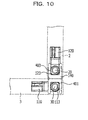
- FIG. 10 is a side view of the linking portion in a 90-degree opened state.
- FIG. 11 is a side view of the linking portion in a 135-degree opened state.
- FIG. 12 is a side view of the linking portion in a 180-degree opened state.
- the upper casing 2 and the lower casing 3 in each state are represented by dashed lines.
- the stopper 113 of the linking member 110 abuts a wall 401 of the housing 140.
- the linking member 110 is restricted from rotating from this state in the direction approaching the linking member 120.
- a stopper 123 of the linking member 120 abuts a wall 402 of the housing 140.
- the linking member 120 is restricted from rotating from this state in the direction approaching the linking member 110.
- the upper casing 2 and the lower casing 3 are opened, because the load torque of the linking member 110 is larger than the load torque of the linking member 120, first, the linking member 110 does not rotate, and the linking member 120 starts to rotate.
- the linking member 120 when the linking member 120 further rotates 45 degrees from the state in FIG. 8 , the state in FIG. 9 is reached.
- the linking member 120 In the rotation from the state in FIG. 8 to the state in FIG. 9 , due to the rotation of the cams 121 and 122, the linking member 120 is made to gradually move in the direction in which the rotation axis 20 of the linking member 120 moves away from the rotation axis 30 of the linking member 110.
- the rotation axis 20 of the linking member 120 and the rotation axis 30 of the linking member 110 are farthest away from each other.
- the distance between the upper casing 2 and the lower casing 3 increases, and the linking member 120 rotates without the edge section 22 of the upper casing 2 interfering with the screen 31 of the lower casing 3.
- the upper casing 2 and the lower casing 3 are further opened from this state, because the load torque of the linking member 110 is still larger than the load torque of the linking member 120, the linking member 110 does not rotate, and the linking member 120 rotates further.
- the linking member 120 rotates 45 degrees from the state in FIG. 9 , the state in FIG. 10 is reached.
- the linking member 120 is made to move in the direction in which the rotation axis 20 of the linking member 120 approaches the rotation axis 30 of the linking member 110.
- the distance between the rotation axis 20 of the linking member 120 and the rotation axis 30 of the linking member 110 in the state in FIG. 10 is the same distance as in the closed state.
- the stopper 123 of the linking member 120 abuts a wall 403 of the housing 140.
- the linking member 120 is restricted from rotating from this state in the direction of further opening.
- the linking member 120 which has a large load torque starts to rotate.
- the linking member 110 rotates 45 degrees from the state in FIG. 10
- the state in FIG. 11 is reached.
- the linking member 110 is made to move in the direction in which the rotation axis 30 of the linking member 110 moves away from the rotation axis 20 of the linking member 120.
- the rotation axis 30 of the linking member 110 and the rotation axis 20 of the linking member 120 are farthest away from each other.
- the distance between the upper casing 2 and the lower casing 3 increases, and the linking member 110 rotates without the edge section 32 of the lower casing 3 interfering with the surface 23 of the upper casing 2.
- the linking member 110 when the linking member 110 further rotates 45 degrees from the state in FIG. 11 , the state in FIG. 12 is reached.
- the linking member 110 In the rotation from the state in FIG. 11 to the state in FIG. 12 , due to the cams 111 and 112 rotating and the restoring force produced by the M-shaped spring 130 (not depicted), the linking member 110 is made to gradually move in the direction in which the rotation axis 30 of the linking member 110 approaches the rotation axis 20 of the linking member 120.
- the distance between the rotation axis 30 of the linking member 110 and the rotation axis 20 of the linking member 120 in the state in FIG. 10 is the same distance as in the closed state.
- the stopper 113 of the linking member 110 abuts a wall 404 of the housing 140
- the stopper 123 of the linking member 120 abuts the wall 403 of the housing 140.
- FIG. 13 is a cross-sectional view of the linking portion in the closed state.
- FIG. 14 is a cross-sectional view of the linking portion in a 45-degree opened state.
- FIG. 15 is a cross-sectional view of the linking portion in a 90-degree opened state.
- FIG. 16 is a cross-sectional view of the linking portion in a 135-degree opened state.
- FIG. 17 is a cross-sectional view of the linking portion in a 180-degree opened state.
- FIG. 13 to FIG. 17 depict the cross section corresponding to the A-A cross section in FIG. 5 in each of the states.
- the upper casing 2 and the lower casing 3 in each state are represented by dashed lines.
- the cam crest of the cam 111 is the cam crest 510.
- the cam crest of the cam 121 is the cam crest 520.
- the cam crest 510 of the cam 111 is in a position away from the cam receiver 149 of the housing 140.
- the cam crest 520 of the cam 121 is in a position away from the cam receiver 150 of the housing 140.
- a force is applied to the cylindrical member 116 and the cylindrical member 126 by the M-shaped spring 130 in the direction in which the rotation axis 20 and the rotation axis 30 become closer. Consequently, in this instance, a state is reached in which the rotation axis 20 and the rotation axis 30 are closest.
- the distance L2 from the rotation axis 20 to the screen 31 of the lower casing 3 is greater than the distance L1 from the rotation axis 20 to the edge section 22.
- This state is the state in which the upper casing 2 is closest to the lower casing 3 in the rotation of the linking member 120, and by ensuring that in this state the edge section 22 does not come into contact with the screen 31 of the lower casing 3, it is possible for the upper casing 2 to rotate without interfering with the lower casing 3. Furthermore, during this process, because the load torque of the cam 111 is larger than the load torque of the cam 121, a state is maintained in which the cam crest 510 abuts the cam receiver 149, and the linking member 110 stops and does not rotate.
- the state in FIG. 16 is reached.
- the cam crest 510 rides up the cam receiver 149, and the linking member 110 is made to gradually move in the direction in which the rotation axis 30 of the linking member 110 moves away from the rotation axis 20 of the linking member 120.
- the distance between the linking member 110 and the linking member 120 is the largest.
- the distance L4 from the rotation axis 30 to the screen 21 of the upper casing 2 is greater than the distance L3 from the rotation axis 30 to the edge section 32.
- This state is the state in which the lower casing 3 is closest to the upper casing 2 in the rotation of the linking member 110, and by ensuring that in this state the edge section 32 does not come into contact with the surface 23 of the upper casing 2, it is possible for the lower casing 3 to rotate without interfering with the upper casing 2.
- the state in FIG. 17 is reached. Due to the rotation from the state in FIG. 16 to the state in FIG. 17 , the cam crest 510 of the cam 111 comes away from the cam receiver 149. Thus, due to the restoring force produced by the M-shaped spring 130, the linking member 110 is made to move in the direction in which the rotation axis 30 of the linking member 110 approaches the rotation axis 20 of the linking member 120. The distance between the rotation axis 30 of the linking member 110 and the rotation axis 20 of the linking member 120 in the state in FIG. 17 is the same distance as when the upper casing 2 and the lower casing 3 are closed. In addition, the state in FIG.
- the stopper 113 of the linking member 110 abuts the wall 404 of the housing 140
- the stopper 123 of the linking member 120 abuts the wall 403 of the housing 140. Therefore, the upper casing 2 and the lower casing 3 are restricted from rotating from this state in the direction of further opening. In other words, the linking member 110 and the linking member 120 do not open any further.
- the state in FIG. 15 is reached. Due to the rotation from the state in FIG. 16 to the state in FIG. 15 , the cam crest 510 of the cam 111 comes away from the cam receiver 149. Thus, due to the restoring force produced by the M-shaped spring 130, the linking member 110 is made to move in the direction in which the rotation axis 30 of the linking member 110 approaches the rotation axis 20 of the linking member 120. The distance between the rotation axis 20 of the linking member 120 and the rotation axis 30 of the linking member 110 in the state in FIG. 15 is the same distance as when the upper casing 2 and the lower casing 3 have closed.
- the state in FIG. 13 is reached. Due to the rotation from the state in FIG. 14 to the state in FIG. 13 , the cam crest 520 of the cam 121 comes away from the cam receiver 150. Thus, due to the restoring force produced by the M-shaped spring 130, the linking member 120 is made to move in the direction in which the rotation axis 20 of the linking member 120 approaches the rotation axis 30 of the linking member 110.
- the distance between the rotation axis 30 of the linking member 110 and the rotation axis 20 of the linking member 120 in the state in FIG. 13 is the same distance as when the upper casing 2 and the lower casing 3 have closed.
- an M-shaped spring is used as a member that shortens the distance between the linking member 110 and the linking member 120 that have been moved apart by the cams
- another member may be used here as long as the member applies a force to the linking member 110 and the linking member 120 in the direction in which the rotation axis 20 and the rotation axis 30 become closer.
- an elastic body such as a coil spring or the like may be arranged between the linking member 110 and the linking member 120.
- a member that presses the linking member 110 toward the linking member 120 from the side opposite the linking member 120, and a member that presses the linking member 120 toward the linking member 110 from the side opposite the linking member 110 may be arranged.
- the load torques of the cam 111, the cam 112, the cam 121, and the cam 122 are adjusted so that the linking member 110 and the linking member 120 rotate in sequence. If the sequence in which the linking member 110 and the linking member 120 rotate is not set by altering the load torques, there is a risk that the cam at the lower casing 3 side of the hinge 1B will move at the same time as when the cam at the upper casing 2 side of the hinge 1A moves, for example. In this instance, there is a risk of the casings twisting, and opening and closing becoming difficult or the casings and the hinges being damaged.
- the linking member 110 and the linking member 120 rotate in sequence as in the present embodiment, it is possible to ensure ease of opening and closing, and to reduce damage to the casings and the hinges.
- the casings and the hinges have high rigidity and if it is certain that an operator will perform opening and closing in a careful manner and so on, the load torques of the cam 111, the cam 112, the cam 121, and the cam 122 do not have to be differed.
- the load torques of the cam 111, the cam 112, the cam 121, and the cam 122 are adjusted such that the upper casing 2 opens first during opening, and the lower casing 3 closes first during closing.
- the load torques of the cams may be adjusted such that the upper casing 2 rotates first at either the opening or the closing timing.
Landscapes
- Engineering & Computer Science (AREA)
- Signal Processing (AREA)
- Mechanical Engineering (AREA)
- Pivots And Pivotal Connections (AREA)
- Telephone Set Structure (AREA)
- Casings For Electric Apparatus (AREA)
- Transmission Devices (AREA)
Abstract
Description
- The embodiment discussed herein relates to an electronic device.
- Portable electronic devices typified by cell telephones and tablet computers have spread rapidly in recent years. Among such electronic devices, there are also a large number of electronic devices that employ folding structures for reasons such as compactness.
- An example of a conventional folding structure for an electronic device is a structure that has a single-axis hinge between two casings, in which the two casings open and close by using the hinge rotating.
- Furthermore, in order to improve durability, there is a conventional technology which has a structure that uses a hinge having two parallel axes. In addition, there is a conventional technology in which a plurality of gears are arranged between two casings to control the opening and closing of the casings. These technologies are disclosed in, for example, Japanese Laid-open Patent Publication No.
2006-228812 2010-250463 - According to an aspect of the invention, an electronic device includes a first casing rotatably supported by a first rotation axis, a second casing rotatably supported by a second rotation axis that is parallel to the first rotation axis, a first cam that is provided on the first rotation axis, rotates about the first rotation axis in accordance with rotation of the first casing, and causes the first casing to move together with the first rotation axis in a direction away from the second rotation axis, a second cam that is provided on the second rotation axis, rotates about the second rotation axis in accordance with rotation of the second casing, and causes the second casing to move together with the second rotation axis in a direction away from the first rotation axis, and an elastic member that applies a force in a direction in which the first rotation axis and the second rotation axis become closer.
-
-
FIG. 1A is a schematic perspective view depicting the closed state of an electronic device according to an embodiment; -
FIG. 1B is a schematic side view depicting the closed state of an electronic device according to an embodiment; -
FIG. 2A is a schematic perspective view depicting the mid-opened/closed state of an electronic device according to an embodiment; -
FIG. 2B is a schematic side view depicting the mid-opened/closed state of an electronic device according to an embodiment; -
FIG. 3A is a schematic perspective view depicting the opened state of an electronic device according to an embodiment; -
FIG. 3B is a schematic side view depicting the opened state of an electronic device according to an embodiment; -
FIG. 4 is a perspective view depicting a specific example of an electronic device; -
FIG. 5 is a perspective view of a hinge; -
FIG. 6 is an exploded perspective view of a hinge; -
FIG. 7 is a schematic diagram for illustrating the shape of a cam; -
FIG. 8 is a side view in which a linking portion in a closed state has been enlarged; -
FIG. 9 is a side view in which a linking portion in a 45-degree opened state has been enlarged; -
FIG. 10 is a side view in which a linking portion in a 90-degree opened state has been enlarged; -
FIG. 11 is a side view in which a linking portion in a 135-degree opened state has been enlarged; -
FIG. 12 is a side view in which a linking portion in a 180-degree opened state has been enlarged; -
FIG. 13 is a cross-sectional view in which a linking portion in a closed state has been enlarged; -
FIG. 14 is a cross-sectional view in which a linking portion in a 45-degree opened state has been enlarged; -
FIG. 15 is a cross-sectional view in which a linking portion in a 90-degree opened state has been enlarged; -
FIG. 16 is a cross-sectional view in which a linking portion in a 135-degree opened state has been enlarged; and -
FIG. 17 is a cross-sectional view in which a linking portion in a 180-degree opened state has been enlarged. - If a structure is adopted in which a single-axis hinge is employed and two casings are opened to 180 degrees, problems such as the following are conceivable. First, there are instances where, in a state in which the two casings have been completely opened, the portion in which the hinge is accommodated protrudes with respect to the opened casing surfaces. If the housing section for the hinge protrudes between the casings in this manner, the space (clearance) between the casings increases by an amount equal to the housing section for the hinge. Therefore, for example, in instances such as when each of the casings has a screen, the space between the two screens greatly increases, and it is not possible to obtain a sense of unity between the two screens.
- Furthermore, there are instances where, in the state in which the two casings have been completely opened, a level difference occurs between one casing and the other casing. If there is a level difference between the casings in this manner, the space between the casings is large due to the level reference. In this instance also, if screens are provided in the casings for example, both screens are not flush and the space widens, and, as expected, it is not possible to obtain a sense of unity between the screens when both screens are used.
- Furthermore, even if the conventional technology that employs a hinge simply having two parallel axes is used, there is a risk of the space between the casings further increasing compared to the single-axis hinge structure, by an amount equivalent to that desired to employ two axes, and it is difficult to narrow the space between the casings. Furthermore, even if the conventional technology that uses gears is used, the space between the portions in which the gears are arranged increases, and it is difficult to narrow the space between the casings. Therefore, if screens are provided in the casings for example, it is not possible to obtain a sense of unity between the screens regardless of which conventional technology is used.
- An embodiment of an electronic device disclosed in the present application is described in detail hereafter on the basis of the drawings. It ought to be noted that the electronic device disclosed in the present application is not restricted by the following embodiment.
-
FIG. 1A is a schematic perspective view depicting the closed state of an electronic device according to the embodiment.FIG. 1B is a schematic side view depicting the closed state of an electronic device according to the embodiment.FIG. 2A is a schematic perspective view depicting the mid-opened/closed state of an electronic device according to the embodiment.FIG. 2B is a schematic side view depicting the mid-opened/closed state of an electronic device according to the embodiment.FIG. 3A is a schematic perspective view depicting the opened state of an electronic device according to the embodiment.FIG. 3B is a schematic side view depicting the opened state of an electronic device according to the embodiment. - As depicted in
FIG. 1A to FIG. 3B , anelectronic device 1 according to the present embodiment has anupper casing 2 and alower casing 3. Theupper casing 2 and thelower casing 3 are linked byhinges upper casing 2 is an example of a "first casing". Furthermore, thelower casing 3 is an example of a "second casing". - The dashed lines in
FIG. 1A ,FIG. 2A , andFIG. 3A , and the dots inFIG. 1B ,FIG. 2B , andFIG. 3B represent therotation axis 20 of theupper casing 2 and therotation axis 30 of thelower casing 3. - The
upper casing 2 is rotatably supported about therotation axis 20 by thehinges FIG. 1A to FIG. 3B , theupper casing 2 turns about therotation axis 20. Furthermore, thelower casing 3 is rotatably supported about therotation axis 30 by thehinges FIG. 1A to FIG. 3B , thelower casing 3 turns about therotation axis 30. - As depicted in
FIG. 1A and FIG. 1B , mutual surfaces of theupper casing 2 and thelower casing 3 come into contact with each other. This state is hereafter referred to as the closed state of theelectronic device 1. The surfaces of theupper casing 2 and thelower casing 3 that come into contact with each other in the closed state of theelectronic device 1 are referred to as the contact surfaces of each of theupper casing 2 and thelower casing 3. Furthermore, the angle formed by theupper casing 2 and thelower casing 3 at this time is 0 degrees. - Furthermore, as depicted in
FIG. 3A and FIG. 3B , theupper casing 2 and thelower casing 3 rotate to a position where the mutual contact surfaces form the same one surface, in other words a position where the mutual contact surfaces are flush. This state is hereafter referred to as the completely opened state of theelectronic device 1. Furthermore, the angle formed by theupper casing 2 and thelower casing 3 at this time is 180 degrees. - In addition, the state during the transition from the closed state of the
electronic device 1 to the completely opened state, in other words the mid-open/close operation state, is represented using the angle formed by theupper casing 2 and thelower casing 3. For example, the state inFIG. 2A and FIG. 2B is a state in which theelectronic device 1 has been opened to 90 degrees. -
FIG. 4 is a perspective view depicting a detailed example of the electronic device.FIG. 4 is the completely opened state of theelectronic device 1. InFIG. 4 , the configurations of thehinge 1A and thehinge 1B are illustrated in more detail. - For example, as depicted in
FIG. 4 , in theupper casing 2 and thelower casing 3 of theelectronic device 1, ascreen 21 and ascreen 31 may be arranged on the surfaces of the sides that come into contact in the closed state of theelectronic device 1. In such instances, in theelectronic device 1 according to the present embodiment, in the completely opened state, thescreen 21 and thescreen 31 are arranged side-by-side so as to form the same one surface. Thus, it is possible to obtain a sense of unity between the screens when thescreen 21 and thescreen 31 are used as a single screen. - Furthermore, although
FIG. 4 depicts a state in which thehinge 1A and thehinge 1B are exposed, thehinge 1A and thehinge 1B may be covered by a cover, for example. By covering thehinge 1A and thehinge 1B with a cover, it is possible to improve the external appearance of theelectronic device 1, and to protect thehinge 1A and thehinge 1B. - Furthermore, in
FIG. 4 , theedge section 22 represents the edge section of thelower casing 3 side of the surface of theupper casing 2 that has thescreen 21. In addition, inFIG. 4 , theedge section 32 represents the edge section of theupper casing 2 side of the surface of thelower casing 3 that has thescreen 31. Theedge section 22 is an example of a "first edge section". Furthermore, theedge section 32 is an example of a "second edge section". - Next, the configurations of the
hinges hinge 1A and thehinge 1B have the same configuration except that the directions in which the cams described hereafter are attached with respect to therotation axis 20 and therotation axis 30 are reversed. An example of thehinge 1A is therefore described hereafter.FIG. 5 is a perspective view of the hinge.FIG. 5 depicts the hinge in a state in which thehinge 1A in the state inFIG. 4 has been removed from theupper casing 2 and thelower casing 3. Furthermore,FIG. 6 is an exploded perspective view of the hinge.FIG. 6 depicts a state in which thehinge 1A of the state inFIG. 5 has been disassembled. - As depicted in
FIG. 5 andFIG. 6 , thehinge 1A has a linkingmember 110, a linkingmember 120, an M-shapedspring 130, and ahousing 140. - The linking
member 110 has acam 111, acam 112, astopper 113, aconnection hole 114, agroove 115, and acylindrical member 116. Thegroove 115 has the same structure as agroove 125 described hereafter; however, thegroove 115 is not depicted due to being positioned at the far side inFIG. 5 . - The linking
member 110 is fixed to thelower casing 3 by using theconnection hole 114. For example, the linkingmember 110 is attached to thelower casing 3 by a bolt or the like being inserted through theconnection hole 114 and fixed to thelower casing 3. Moreover, the linkingmember 120 is similarly fixed to theupper casing 2 by using aconnection hole 124. - The
cylindrical member 116 is hollow and has ahole 117. The central axis of thecylindrical member 116 is aligned with therotation axis 30 when the linkingmember 110 is attached to thelower casing 3 by way of theconnection hole 114. - The
cam 111 and thecam 112 are plate cams. Thecam 111 and thecam 112 are arranged surrounding thecylindrical member 116. For example, thecam 111 and thecam 112 have through holes provided such that the centers are aligned with the central axis of thecylindrical member 116 and therotation axis 30, and thecylindrical member 116 is inserted through the through holes as a camshaft so that thecam 111 and thecam 112 are fixed in predetermined positions of thecylindrical member 116. Alternatively, for example, thecam 111 and thecam 112 may be integrally formed with thecylindrical member 116 so as to be positioned in the predetermined positions of thecylindrical member 116. The cam crests of thecam 111 and thecam 112 extend in a direction orthogonal to the central axis of thecylindrical member 116. Furthermore, in a state in which the linkingmember 110 is attached to thelower casing 3, thecam 111 is arranged in a position further away from thelower casing 3 than thecam 112 along therotation axis 30. - Here, the details of the shape of the
cam 111 are described with reference toFIG. 7. FIG. 7 is a schematic diagram for illustrating the cam shape.FIG. 7 is a view of the plate-shapedcam 111 having been placed flat on a surface. As depicted inFIG. 7 , in thecam crest 200 of thecam 111, the inclination angle of oneinclined section 201 is smaller than the inclination angle of the otherinclined section 202. - When the
cam 111 rotates in the rotation direction R1, thecam crest 200 rides up acam receiver 149 from theinclined section 202 side. In this instance, because the inclination angle of theinclined section 202 is large compared to theinclined section 201, a large force is desired for the rotation of thecam 111 in order for thecam crest 200 to ride up thecam receiver 149. In other words, the torque desired for the rotation of thecam 111 is large. The torque desired for the rotation is hereafter referred to as "load torque". - On the other hand, when the
cam 111 rotates in the rotation direction R2, thecam crest 200 rides up thecam receiver 149 from theinclined section 201 side. In this instance, because the inclination angle of theinclined section 201 is small compared to theinclined section 202, the force desired for the rotation of thecam 111 in order for thecam crest 200 to ride up thecam receiver 149 is small compared to rotation in the rotation direction R1. In other words, the load torque of thecam 111 is small. - In this way, in the
cam 111, the angles of inclination of both inclined surfaces of thecam crest 200 are differed, and the load torques according to the rotation direction are thereby differed. Although thecam 111 is described here, the angles of inclination of both inclined surfaces of the cam crests are likewise different for thecam 112, acam 121, and acam 122. - In the
electronic device 1 according to the present embodiment, for example, when theupper casing 2 and thelower casing 3 are closed, load torque is applied to the cams of thehinge 1A such that thelower casing 3 rotates before theupper casing 2. Furthermore, when theupper casing 2 and thelower casing 3 are opened, load torque is applied to the cams of thehinge 1A such that theupper casing 2 rotates before thelower casing 3. - To be specific, because the
cam 111 and thecam 112 are cams of the linkingmember 110 which is fixed to thelower casing 3, the inclination angles of the inclined sections of the cam crests at the sides that ride up when theupper casing 2 and thelower casing 3 are opened are large. Furthermore, in thecam 111 and thecam 112, the inclination angles of the inclined sections of the cam crests at the sides that ride up when theupper casing 2 and thelower casing 3 are closed are small. - In other words, when viewed from a surface side that includes the thickness direction of the
electronic device 1, thecam 111 and thecam 112 have the shape depicted inFIG. 7 . Conversely, when viewed from a surface side that includes the thickness direction of theelectronic device 1, the cams of the linking member at thelower casing 3 side of thehinge 1B have a shape in which the inclination of the inclined sections is the reverse of that inFIG. 7 , in other words a shape in which left and right inFIG. 7 are reversed. Furthermore, when viewed from a surface side that includes the thickness direction of theelectronic device 1, thecam 121 and thecam 122 have the shape depicted inFIG. 7 . Conversely, when viewed from a surface side that includes the thickness direction of theelectronic device 1, the cams of the linking member at theupper casing 2 side of thehinge 1B have a shape in which the inclination of the inclined sections is the reverse of that inFIG. 7 , in other words a shape in which the left and right inFIG. 7 are reversed. - In addition, the cam crest of the cam 111 (the
cam crest 200 inFIG. 7 ) is described with reference toFIG. 4 andFIG. 5 . The cross section in which thecam crest 200 of thecam 111 is orthogonal to therotation axis 30 is described. Thecam crest 200 of thecam 111 protrudes in the direction of theedge section 32 inFIG. 4 . In other words, thecam crest 200 of thecam 111 is arranged such that, when the line joining therotation axis 30, theedge section 32 of thelower casing 3, and therotation axis 20 forms one straight line due to the linkingmember 110 rotating about therotation axis 30, the apex of the cam crest is positioned on that straight line. This state is the state in which theupper casing 2 and thelower casing 3 have been opened 45 degrees. In other words, thecam 111 is formed such that, in the state in which theupper casing 2 and thelower casing 3 have been opened 45 degrees, the apex of thecam crest 200 is positioned on thecam receiver 149. The reason that thecam crest 200 of thecam 111 is arranged so as to protrude in the direction of theedge section 32 is because, when thelower casing 3 rotates, theedge section 32 approaches theupper casing 2 to the closest extent on the basis of therotation axis 30. - In this way, the
cam crest 200 of thecam 111 is formed such that, when the line joining therotation axis 30, theedge section 32, and therotation axis 20 forms a straight line, therotation axis 30 which is the central axis of thecylindrical member 116 and therotation axis 20 which is the central axis of acylindrical member 126 are farthest away from each other. For example, thecam crest 200 of thecam 111 has a height such that, in the state in which theupper casing 2 and thelower casing 3 have been opened 45 degrees, the distance between therotation axis 20 and therotation axis 30 increases to equal to or greater than the length obtained by totaling the distance from therotation axis 20 to the screen 21 (refer toFIG. 4 ) of theupper casing 2 and the distance from therotation axis 30 to theedge section 32. - Furthermore, although the
cam 111 has been described here as an example, thecam 112 also has the same shape as thecam 111. Furthermore, in thecam 121 and thecam 122, the cam crests of thecam 121 and thecam 122 are arranged such that, when the line joining therotation axis 20, the edge section 22 (refer toFIG. 4 ) of theupper casing 2, and therotation axis 30 forms one straight line, the central axis of thecylindrical member 116 and the central axis of thecylindrical member 126 are farthest away from each other. This state is the state in which theupper casing 2 and thelower casing 3 have been opened 135 degrees. Thecam 121 and thecam 122 are also the same as thecam 111 with respect to the rest of the structure other than the cam crest. Thecam 111 and thecam 112 are examples of a "first cam". Furthermore, thecam 121 and thecam 122 are examples of a "second cam". - As depicted in
FIG. 5 , thestopper 113 is formed by part of the end section of thecylindrical member 116 that is at the far side from thelower casing 3 in theelectronic device 1 protruding in a direction orthogonal to the central axis of thecylindrical member 116. Thestopper 113 is arranged in a position closer to thelower casing 3 than thecam 111 along therotation axis 30. - Furthermore, the
groove 115 is provided in the surface facing thelower casing 3 side of the linkingmember 110. Thegroove 115 links with the internal space of thelower casing 3 when the linkingmember 110 is attached to thelower casing 3 by way of theconnection hole 114. In addition, thegroove 115 is linked with thehole 117. Thus, a cable that extends from a member arranged in the internal space of thelower casing 3 extends outside by way of thegroove 115 and thehole 117 of the linkingmember 110. The cable that extends outside from thehole 117 is able to connect to a member arranged in the internal space of theupper casing 2 by way of ahole 127 and thegroove 125 of the linkingmember 120. Thus, it is possible to connect the member arranged in the internal space of thelower casing 3 and the member arranged in the internal space of theupper casing 2. - As depicted in
FIG. 6 , thehousing 140 has a H-shaped longitudinal cross section that has arecess section 153 and arecess section 154. The linkingmember 110 is accommodated in thehousing 140 along the dashed line P, and is fitted into therecess section 153 of thehousing 140. Furthermore, the linkingmember 120 is accommodated in thehousing 140 along the dashed line Q, and the linkingmember 120 is fitted into therecess section 154 of thehousing 140. As depicted inFIG. 5 , the linkingmember 110 is stored in therecess section 153, and the linkingmember 120 is accommodated in therecess section 154. Thehousing 140 having therecess section 153 and therecess section 154 is open in the directions in which the central axis of thecylindrical member 116 that is therotation axis 30 of thelower casing 3, and the central axis of thecylindrical member 126 that is therotation axis 20 of theupper casing 2 move away from each other. - In addition, in the present embodiment, the
housing 140 hascam relief sections 141 to 148 in order to reduce size. With regard to thecam 111, the cam crest is received in thecam relief section 141 when the linkingmember 110 rotates in the direction in which thelower casing 3 opens. Furthermore, with regard to thecam 112, the cam crest is received in thecam relief section 143 when the linkingmember 110 rotates in the direction in which thelower casing 3 opens. With regard to thecam 111, the cam crest is received in thecam relief section 145 when the linkingmember 110 rotates in the direction in which thelower casing 3 closes. Furthermore, with regard to thecam 112, the cam crest is received in thecam relief section 147 when the linkingmember 110 rotates in the direction in which thelower casing 3 closes. - Similarly, with regard to the
cam 121, the cam crest is received in thecam relief section 142 when the linkingmember 120 rotates in the direction in which theupper casing 2 opens. Furthermore, with regard to thecam 122, the cam crest is received in thecam relief section 144 when the linkingmember 120 rotates in the direction in which theupper casing 2 opens. With regard to thecam 121, the cam crest is received in thecam relief section 146 when the linkingmember 120 rotates in the direction in which theupper casing 2 closes. Furthermore, with regard to thecam 122, the cam crest is received in the cam relief section 148 when the linkingmember 120 rotates in the direction in which theupper casing 2 closes. - For example,
FIG. 5 depicts a state in which the cam crest of thecam 111 is received in thecam relief section 141, and the cam crest of thecam 112 is received in thecam relief section 143. In addition,FIG. 5 depicts a state in which the cam crest of thecam 121 is received in thecam relief section 142, and the cam crest of thecam 122 is received in thecam relief section 144. - For example, if the
cam 111, thecam 112, thecam 121, and thecam 122 after rotation were stored inside thehousing 140, thehousing 140 would have a size that is one size larger than the cams. In contrast, as in the present embodiment, by employing a structure in which after rotation thecam 111, thecam 112, thecam 121, and thecam 122 are stored protruding from the internal space of thehousing 140, the size of thehousing 140 is approximately the same size as the cams. Thus, it is possible for thehousing 140 to be made compact. - Furthermore, as depicted in
FIG. 6 , thehousing 140 hascam receivers 149 to 152. Thecam receiver 149 comes into contact with thecam 111 that rotates, receives a force from thecam 111, and the central axis of thecylindrical member 116 is made to move in the direction away from the central axis of thecylindrical member 126. In other words, therotation axis 30 moves in the direction away from therotation axis 20 due to the force from thecam receiver 149. In the present embodiment, thecam receiver 149 has a cam crest that protrudes from the central axis of thecylindrical member 126 toward the central axis of thecylindrical member 116. Thus, it is possible for the central axis of thecylindrical member 116 to be moved away from the central axis of thecylindrical member 126 to a considerable extent when the cam crests of the cams are positioned on the line joining the central axis of thecylindrical member 126 and the central axis of thecylindrical member 116. - The
cam receiver 150 is a cam receiver that corresponds to thecam 112. Thecam receiver 150 also causes the central axis of thecylindrical member 126 to move in the direction away from the central axis of thecylindrical member 116. Thecam receiver 151 is a cam receiver that corresponds to thecam 121. Thecam receiver 152 is a cam receiver that corresponds to thecam 122. Thecam receiver 151 and thecam receiver 152 also cause the central axis of thecylindrical member 126 to move in the direction away from the central axis of thecylindrical member 116. - In addition, the
housing 140 has anopening 155 for contact to be made from outside of thehousing 140 with thecylindrical member 116 and thecylindrical member 126 stored in therecess section 153 and therecess section 154. Theopening 155 is provided in the surface of thehousing 140 that is parallel with a plane that joins the central axis of thecylindrical member 116 and the central axis of thecylindrical member 126. - As depicted in
FIG. 6 , the M-shapedspring 130 is a spring that has an M character-type shape having abent section 131 and abent section 132. As depicted inFIG. 5 , the M-shapedspring 130 is inserted from theopening 155 of thehousing 140. In the M-shapedspring 130, thecylindrical member 116 that is accommodated in therecess section 153 is accommodated in thebent section 131. Furthermore, in the M-shapedspring 130, thecylindrical member 126 that is accommodated in therecess section 154 of thehousing 140 is accommodated in thebent section 132. When the distance between the central axis of thecylindrical member 126 and the central axis of thecylindrical member 116 increases due to a separation force caused by the action of the cam crests of the rotated cams, the M-shapedspring 130 applies a restoring force to the two cylindrical members in the direction in which the distance is restored. - For example, when the rotation of the linking
member 110 finishes and the cam crests of thecam 111 and thecam 112 come away from thecam receiver 149 and thecam receiver 151, the M-shapedspring 130 draws thecylindrical member 116 toward thecylindrical member 126 side in the direction in which the central axis of thecylindrical member 116 and the central axis of thecylindrical member 126 become closer. Furthermore, when the rotation of the linkingmember 120 finishes and the cam crests of thecam 121 and thecam 122 come away from thecam receiver 150 and thecam receiver 152, the M-shapedspring 130 draws thecylindrical member 126 toward thecylindrical member 116 side in the direction in which the central axis of thecylindrical member 126 and the central axis of thecylindrical member 116 become closer. - Next, the operation during rotation of the
upper casing 2 and thelower casing 3 is described with reference toFIG. 8 to FIG. 12 .FIG. 8 is a side view of the linking portion in the closed state.FIG. 9 is a side view of the linking portion in a 45-degree opened state.FIG. 10 is a side view of the linking portion in a 90-degree opened state.FIG. 11 is a side view of the linking portion in a 135-degree opened state.FIG. 12 is a side view of the linking portion in a 180-degree opened state. InFIG. 8 to FIG. 12 , theupper casing 2 and thelower casing 3 in each state are represented by dashed lines. - As depicted in
FIG. 8 , in the state in which theupper casing 2 and thelower casing 3 are closed, thestopper 113 of the linkingmember 110 abuts awall 401 of thehousing 140. Thus, the linkingmember 110 is restricted from rotating from this state in the direction approaching the linkingmember 120. Furthermore, astopper 123 of the linkingmember 120 abuts awall 402 of thehousing 140. Thus, the linkingmember 120 is restricted from rotating from this state in the direction approaching the linkingmember 110. In this state, when theupper casing 2 and thelower casing 3 are opened, because the load torque of the linkingmember 110 is larger than the load torque of the linkingmember 120, first, the linkingmember 110 does not rotate, and the linkingmember 120 starts to rotate. - Next, when the linking
member 120 further rotates 45 degrees from the state inFIG. 8 , the state inFIG. 9 is reached. In the rotation from the state inFIG. 8 to the state inFIG. 9 , due to the rotation of thecams member 120 is made to gradually move in the direction in which therotation axis 20 of the linkingmember 120 moves away from therotation axis 30 of the linkingmember 110. In the state inFIG. 9 , therotation axis 20 of the linkingmember 120 and therotation axis 30 of the linkingmember 110 are farthest away from each other. Thus, the distance between theupper casing 2 and thelower casing 3 increases, and the linkingmember 120 rotates without theedge section 22 of theupper casing 2 interfering with thescreen 31 of thelower casing 3. When theupper casing 2 and thelower casing 3 are further opened from this state, because the load torque of the linkingmember 110 is still larger than the load torque of the linkingmember 120, the linkingmember 110 does not rotate, and the linkingmember 120 rotates further. - Next, when the linking
member 120 rotates 45 degrees from the state inFIG. 9 , the state inFIG. 10 is reached. In the rotation from the state inFIG. 9 to the state inFIG. 10 , due to thecams spring 130, the linkingmember 120 is made to move in the direction in which therotation axis 20 of the linkingmember 120 approaches therotation axis 30 of the linkingmember 110. The distance between therotation axis 20 of the linkingmember 120 and therotation axis 30 of the linkingmember 110 in the state inFIG. 10 is the same distance as in the closed state. In addition, in the state inFIG. 10 , thestopper 123 of the linkingmember 120 abuts awall 403 of thehousing 140. Thus, the linkingmember 120 is restricted from rotating from this state in the direction of further opening. When theupper casing 2 and thelower casing 3 are further opened from this state, because the linkingmember 120 is restricted from rotating, the linkingmember 110 which has a large load torque starts to rotate. - Next, when the linking
member 110 rotates 45 degrees from the state inFIG. 10 , the state inFIG. 11 is reached. In the rotation from the state inFIG. 10 to the state inFIG. 11 , due to the rotation of thecams member 110 is made to move in the direction in which therotation axis 30 of the linkingmember 110 moves away from therotation axis 20 of the linkingmember 120. In the state inFIG. 11 , therotation axis 30 of the linkingmember 110 and therotation axis 20 of the linkingmember 120 are farthest away from each other. Thus, the distance between theupper casing 2 and thelower casing 3 increases, and the linkingmember 110 rotates without theedge section 32 of thelower casing 3 interfering with thesurface 23 of theupper casing 2. When the linkingmember 110 and the linkingmember 120 are further opened from this state, because the linkingmember 120 is restricted from rotating by thestopper 123, the linkingmember 120 does not rotate, and the linkingmember 110 rotates. - Next, when the linking
member 110 further rotates 45 degrees from the state inFIG. 11 , the state inFIG. 12 is reached. In the rotation from the state inFIG. 11 to the state inFIG. 12 , due to thecams member 110 is made to gradually move in the direction in which therotation axis 30 of the linkingmember 110 approaches therotation axis 20 of the linkingmember 120. The distance between therotation axis 30 of the linkingmember 110 and therotation axis 20 of the linkingmember 120 in the state inFIG. 10 is the same distance as in the closed state. In addition, in the state inFIG. 12 , thestopper 113 of the linkingmember 110 abuts awall 404 of thehousing 140, and thestopper 123 of the linkingmember 120 abuts thewall 403 of thehousing 140. Thus, the linkingmember 110 and the linkingmember 120 are restricted from rotating from this state in the direction of further opening. In other words, theupper casing 2 and thelower casing 3 do not open any further. - Next, the movements of the cams and axes during rotation of the electronic device are explained with reference to
FIG. 13 to FIG. 17 .FIG. 13 is a cross-sectional view of the linking portion in the closed state.FIG. 14 is a cross-sectional view of the linking portion in a 45-degree opened state.FIG. 15 is a cross-sectional view of the linking portion in a 90-degree opened state.FIG. 16 is a cross-sectional view of the linking portion in a 135-degree opened state.FIG. 17 is a cross-sectional view of the linking portion in a 180-degree opened state.FIG. 13 to FIG. 17 depict the cross section corresponding to the A-A cross section inFIG. 5 in each of the states. InFIG. 13 to FIG. 17 , theupper casing 2 and thelower casing 3 in each state are represented by dashed lines. - Here, the cam crest of the
cam 111 is thecam crest 510. Furthermore, the cam crest of thecam 121 is thecam crest 520. As depicted inFIG. 13 , in the state in which theupper casing 2 and thelower casing 3 are closed, thecam crest 510 of thecam 111 is in a position away from thecam receiver 149 of thehousing 140. Furthermore, in the state in which theupper casing 2 and thelower casing 3 are closed, thecam crest 520 of thecam 121 is in a position away from thecam receiver 150 of thehousing 140. In this instance, a force is applied to thecylindrical member 116 and thecylindrical member 126 by the M-shapedspring 130 in the direction in which therotation axis 20 and therotation axis 30 become closer. Consequently, in this instance, a state is reached in which therotation axis 20 and therotation axis 30 are closest. - In addition, when the
upper casing 2 and thelower casing 3 open, a force is applied to the linkingmember 110 and the linkingmember 120 for rotation from the state inFIG. 13 in the direction in which the linkingmember 110 and the linkingmember 120 move away from each other, in other words in the opening direction. Here, as depicted inFIG. 13 , the inclination angle of theinclined section 511 at the side of thecam 111 that rides up thecam receiver 149 is larger than the inclination angle of theinclined section 521 at the side of thecam 121 that rides up thecam receiver 150. Therefore, thecam 111 has a larger load torque than thecam 121. Consequently, when theupper casing 2 and thelower casing 3 are opened, theinclined section 521 of thecam 121 rides up thecam receiver 150 before theinclined section 511 of thecam 111 rides up thecam receiver 149. In other words, thecam 121 starts to rotate before thecam 111. - Next, when the
cam 121 rotates 45 degrees from the state inFIG. 13 , the state inFIG. 14 is reached. In the rotation from the state inFIG. 13 to the state inFIG. 14 , due to the rotation of thecam 121, thecam crest 520 rides up thecam receiver 150, and the linkingmember 120 is made to gradually move in the direction in which therotation axis 20 of the linkingmember 120 moves away from therotation axis 30 of the linkingmember 110. When the apex of thecam crest 520 of thecam 121 rides up thecam receiver 150, the distance between the linkingmember 120 and the linkingmember 110 is the largest. In the state in which therotation axis 20, theedge section 22 of theupper casing 2, and therotation axis 30 form one straight line, the distance L2 from therotation axis 20 to thescreen 31 of thelower casing 3 is greater than the distance L1 from therotation axis 20 to theedge section 22. This state is the state in which theupper casing 2 is closest to thelower casing 3 in the rotation of the linkingmember 120, and by ensuring that in this state theedge section 22 does not come into contact with thescreen 31 of thelower casing 3, it is possible for theupper casing 2 to rotate without interfering with thelower casing 3. Furthermore, during this process, because the load torque of thecam 111 is larger than the load torque of thecam 121, a state is maintained in which thecam crest 510 abuts thecam receiver 149, and the linkingmember 110 stops and does not rotate. - Next, when the
cam 121 further rotates 45 degrees from the state inFIG. 14 in the opening direction, the state inFIG. 15 is reached. Due to the rotation from the state inFIG. 14 to the state inFIG. 15 , thecam crest 520 of thecam 121 comes away from thecam receiver 150. Thus, due to the restoring force produced by the M-shapedspring 130, the linkingmember 120 is made to move in the direction in which therotation axis 20 of the linkingmember 120 approaches therotation axis 30 of the linkingmember 110. The distance between therotation axis 20 of the linkingmember 120 and therotation axis 30 of the linkingmember 110 in the state inFIG. 15 is the same distance as in the closed state. In addition, the state inFIG. 15 corresponds to the state inFIG. 10 , in which thestopper 123 of the linkingmember 120 abuts thehousing 140, and the linkingmember 120 is restricted from rotating. Therefore, the linkingmember 110, which has a large torque, starts to rotate from this state. In other words, theinclined section 511 of thecam crest 510 of thecam 111 rides up thecam receiver 149. - Next, when the
cam 111 further rotates 45 degrees from the state inFIG. 15 , the state inFIG. 16 is reached. In the rotation from the state inFIG. 15 to the state inFIG. 16 , due to the rotation of thecam 111, thecam crest 510 rides up thecam receiver 149, and the linkingmember 110 is made to gradually move in the direction in which therotation axis 30 of the linkingmember 110 moves away from therotation axis 20 of the linkingmember 120. When the apex of thecam crest 510 of thecam 111 rides up thecam receiver 149, the distance between the linkingmember 110 and the linkingmember 120 is the largest. In the state in which therotation axis 20, theedge section 32 of thelower casing 3, and therotation axis 30 form one straight line, the distance L4 from therotation axis 30 to thescreen 21 of theupper casing 2 is greater than the distance L3 from therotation axis 30 to theedge section 32. This state is the state in which thelower casing 3 is closest to theupper casing 2 in the rotation of the linkingmember 110, and by ensuring that in this state theedge section 32 does not come into contact with thesurface 23 of theupper casing 2, it is possible for thelower casing 3 to rotate without interfering with theupper casing 2. - Next, when the
cam 111 further rotates 45 degrees from the state inFIG. 16 , the state inFIG. 17 is reached. Due to the rotation from the state inFIG. 16 to the state inFIG. 17 , thecam crest 510 of thecam 111 comes away from thecam receiver 149. Thus, due to the restoring force produced by the M-shapedspring 130, the linkingmember 110 is made to move in the direction in which therotation axis 30 of the linkingmember 110 approaches therotation axis 20 of the linkingmember 120. The distance between therotation axis 30 of the linkingmember 110 and therotation axis 20 of the linkingmember 120 in the state inFIG. 17 is the same distance as when theupper casing 2 and thelower casing 3 are closed. In addition, the state inFIG. 17 corresponds to the state inFIG. 12 , thestopper 113 of the linkingmember 110 abuts thewall 404 of thehousing 140, and thestopper 123 of the linkingmember 120 abuts thewall 403 of thehousing 140. Therefore, theupper casing 2 and thelower casing 3 are restricted from rotating from this state in the direction of further opening. In other words, the linkingmember 110 and the linkingmember 120 do not open any further. - Next, the instance where the
upper casing 2 and thelower casing 3 are closed is described in the order ofFIG. 17 to FIG. 13 . - When the
upper casing 2 and thelower casing 3 are closed, a force is applied to the linkingmember 110 and the linkingmember 120 for rotation from the state inFIG. 17 in the direction in which the linkingmember 110 and the linkingmember 120 become closer, in other words in the closing direction. Here, as depicted inFIG. 17 , the inclination angle of theinclined section 512 at the side of thecam 111 that rides up thecam receiver 149 is larger than the inclination angle of theinclined section 522 at the side of thecam 121 that rides up thecam receiver 150. Therefore, thecam 121 has a larger load torque than thecam 111. Consequently, thecam 111 starts to rotate before thecam 121. Theinclined section 512 of thecam 111 rides up thecam receiver 149 before theinclined section 522 of thecam 121 rides up thecam receiver 150. - Next, when the
cam 111 further rotates 45 degrees from the state inFIG. 17 in the closing direction, the state inFIG. 16 is reached. In the rotation from the state inFIG. 17 to the state inFIG. 16 , due to the rotation of thecam 111, thecam crest 510 rides up thecam receiver 149, and the linkingmember 110 is made to gradually move in the direction in which therotation axis 30 of the linkingmember 110 moves away from therotation axis 20 of the linkingmember 120. When the apex of thecam crest 510 of thecam 111 rides up thecam receiver 149, the distance between the linkingmember 110 and the linkingmember 120 increases to the largest and the state inFIG. 16 is reached. - Next, when the
cam 111 further rotates 45 degrees from the state inFIG. 16 in the closing direction, the state inFIG. 15 is reached. Due to the rotation from the state inFIG. 16 to the state inFIG. 15 , thecam crest 510 of thecam 111 comes away from thecam receiver 149. Thus, due to the restoring force produced by the M-shapedspring 130, the linkingmember 110 is made to move in the direction in which therotation axis 30 of the linkingmember 110 approaches therotation axis 20 of the linkingmember 120. The distance between therotation axis 20 of the linkingmember 120 and therotation axis 30 of the linkingmember 110 in the state inFIG. 15 is the same distance as when theupper casing 2 and thelower casing 3 have closed. In addition, when theupper casing 2 and thelower casing 3 are closed from the state inFIG. 15 , because thestopper 113 of the linkingmember 110 abuts thehousing 140, and the linkingmember 110 is restricted from rotating as depicted inFIG. 9 , the linkingmember 120 starts to rotate. - Next, when the
cam 121 further rotates 45 degrees from the state inFIG. 15 in the closing direction, the state inFIG. 14 is reached. In the rotation from the state inFIG. 15 to the state inFIG. 14 , due to the rotation of thecam 121, thecam crest 520 rides up thecam receiver 150, and the linkingmember 120 is made to move in the direction in which therotation axis 20 of the linkingmember 120 moves away from therotation axis 30 of the linkingmember 110. When the apex of thecam crest 520 of thecam 121 rides up thecam receiver 150, the distance between the linkingmember 120 and the linkingmember 110 increases to the largest and the state inFIG. 14 is reached. - Next, when the
cam 121 further rotates 45 degrees from the state inFIG. 14 in the closing direction, the state inFIG. 13 is reached. Due to the rotation from the state inFIG. 14 to the state inFIG. 13 , thecam crest 520 of thecam 121 comes away from thecam receiver 150. Thus, due to the restoring force produced by the M-shapedspring 130, the linkingmember 120 is made to move in the direction in which therotation axis 20 of the linkingmember 120 approaches therotation axis 30 of the linkingmember 110. The distance between therotation axis 30 of the linkingmember 110 and therotation axis 20 of the linkingmember 120 in the state inFIG. 13 is the same distance as when theupper casing 2 and thelower casing 3 have closed. - As described above, in the electronic device according to the present embodiment, during rotation the space between rotation axes is widened using cams, casings move to positions where the casings do not interfere with each other, and after rotation the space between the rotation axes is restored by the force of a spring. By moving the two casings away from each other during rotation, and bringing the casings close together after rotation, it is possible for rotation to be performed smoothly while reducing the space between the casings when the rotation has finished. By reducing the space between the casings when the rotation has finished, if screens are arranged in the upper casing and the lower casing, the space between both screens is shorter when the upper casing and the lower casing have been completely opened, and it is possible to obtain a sense of unity between the screens when the two screens are used as a single screen.
- In the above, although an M-shaped spring is used as a member that shortens the distance between the linking
member 110 and the linkingmember 120 that have been moved apart by the cams, another member may be used here as long as the member applies a force to the linkingmember 110 and the linkingmember 120 in the direction in which therotation axis 20 and therotation axis 30 become closer. For example, an elastic body such as a coil spring or the like may be arranged between the linkingmember 110 and the linkingmember 120. In addition, a member that presses the linkingmember 110 toward the linkingmember 120 from the side opposite the linkingmember 120, and a member that presses the linkingmember 120 toward the linkingmember 110 from the side opposite the linkingmember 110 may be arranged. - In the present embodiment, the load torques of the
cam 111, thecam 112, thecam 121, and thecam 122 are adjusted so that the linkingmember 110 and the linkingmember 120 rotate in sequence. If the sequence in which the linkingmember 110 and the linkingmember 120 rotate is not set by altering the load torques, there is a risk that the cam at thelower casing 3 side of thehinge 1B will move at the same time as when the cam at theupper casing 2 side of thehinge 1A moves, for example. In this instance, there is a risk of the casings twisting, and opening and closing becoming difficult or the casings and the hinges being damaged. In other words, by making the linkingmember 110 and the linkingmember 120 rotate in sequence as in the present embodiment, it is possible to ensure ease of opening and closing, and to reduce damage to the casings and the hinges. However, if the casings and the hinges have high rigidity and if it is certain that an operator will perform opening and closing in a careful manner and so on, the load torques of thecam 111, thecam 112, thecam 121, and thecam 122 do not have to be differed. - Furthermore, in the present embodiment, the load torques of the
cam 111, thecam 112, thecam 121, and thecam 122 are adjusted such that theupper casing 2 opens first during opening, and thelower casing 3 closes first during closing. This is because, when thelower casing 3 is placed on a flat surface, if theupper casing 2 rotates when thelower casing 3 has finished rotating in the opening direction, there is a risk that theupper casing 2 will protrude considerably in the direction of the surface on which thelower casing 3 is placed, and it will no longer be possible to place thelower casing 3 in a flat manner. However, if thelower casing 3 does not have to be placed in a flat manner, the order in which rotation occurs is not restricted to this. For example, the load torques of the cams may be adjusted such that theupper casing 2 rotates first at either the opening or the closing timing. - All examples and conditional language recited herein are intended for pedagogical purposes to aid the reader in understanding the invention and the concepts contributed by the inventor to furthering the art, and are to be construed as being without limitation to such specifically recited examples and conditions, nor does the organization of such examples in the specification relate to a showing of the superiority and inferiority of the invention. Although the embodiment of the present invention has been described in detail, it should be understood that the various changes, substitutions, and alterations could be made hereto without departing from the spirit and scope of the invention.
Claims (8)
- An electronic device comprising:a first casing rotatably supported by a first rotation axis;a second casing rotatably supported by a second rotation axis that is parallel to the first rotation axis;a first cam that is provided on the first rotation axis, rotates about the first rotation axis in accordance with rotation of the first casing, and causes the first casing to move together with the first rotation axis in a direction away from the second rotation axis;a second cam that is provided on the second rotation axis, rotates about the second rotation axis in accordance with rotation of the second casing, and causes the second casing to move together with the second rotation axis in a direction away from the first rotation axis; andan elastic member that applies a force in a direction in which the first rotation axis and the second rotation axis become closer.
- The electronic device according to claim 1,
wherein the first cam causes the first rotation axis to move to a position where the first casing does not interfere with the second casing when the first casing rotates,
and the second cam causes the second rotation axis to move to a position where the second casing does not interfere with the first casing when the second casing rotates. - The electronic device according to claim 1,
wherein the first cam protrudes from the first rotation axis toward a first edge section of the first casing that faces the second casing when the first casing rotates,
and the second cam protrudes from the second rotation axis toward a second edge section of the second casing that faces the first casing when the second casing rotates. - The electronic device according to claim 3,
wherein the first cam has a height such that, in a state in which the first casing rotates and the apex of a cam crest is positioned on a straight line that joins the first rotation axis and the second rotation axis, the distance obtained by adding the distance from the first rotation axis to the apex of the cam crest of the first cam and the distance from the second rotation axis to the apex of the cam crest of the first cam is longer than the distance obtained by adding the distance from the apex of the first edge section to the first rotation axis and the distance from a surface of the second casing that faces the first casing when the first casing rotates, to the second rotation axis,
and the second cam has a height such that, in a state in which the second casing rotates and the apex of a cam crest is positioned on a straight line that joins the first rotation axis and the second rotation axis, the distance obtained by adding the distance from the first rotation axis to the apex of the cam crest of the second cam and the distance from the second rotation axis to the apex of the cam crest of the second cam is longer than the distance obtained by adding the distance from the apex of the second edge section to the second rotation axis and the distance from a surface of the first casing that faces the second casing to the first rotation axis. - The electronic device according to claim 1,
wherein the elastic member is an M-shaped spring that has bent sections in which the first rotation axis and the second rotation axis are separately housed. - The electronic device according to claim 1,
wherein, in the first cam and the second cam, the load torque when the first casing turns and the load torque when the second casing turns are different. - The electronic device according to claim 6,
wherein, in the first cam and the second cam, when the first casing and the second casing open, the load torque when the first casing turns is less than the load torque when the second casing turns, and when the first casing and the second casing close, the load torque when the first casing turns is greater than the load torque when the second casing turns. - The electronic device according to claim 7,
wherein, the inclination angle at the side where a cam receiver for the first cam is pressed when the first casing and the second casing open is less than the inclination angle at the side where a cam receiver for the second cam is pressed, and the inclination angle at the side where the cam receiver for the first cam is pressed when the first casing and the second casing close is greater than the inclination angle at the side where the cam receiver for the second cam is pressed.
Applications Claiming Priority (1)
| Application Number | Priority Date | Filing Date | Title |
|---|---|---|---|
| JP2013067665A JP6197327B2 (en) | 2013-03-27 | 2013-03-27 | Electronics |
Publications (2)
| Publication Number | Publication Date |
|---|---|
| EP2797296A2 true EP2797296A2 (en) | 2014-10-29 |
| EP2797296A3 EP2797296A3 (en) | 2015-03-18 |
Family
ID=50189600
Family Applications (1)
| Application Number | Title | Priority Date | Filing Date |
|---|---|---|---|
| EP14157516.7A Withdrawn EP2797296A3 (en) | 2013-03-27 | 2014-03-03 | Electronic device |
Country Status (4)
| Country | Link |
|---|---|
| US (1) | US9598886B2 (en) |
| EP (1) | EP2797296A3 (en) |
| JP (1) | JP6197327B2 (en) |
| CN (1) | CN104080288B (en) |
Cited By (9)
| Publication number | Priority date | Publication date | Assignee | Title |
|---|---|---|---|---|
| WO2017087343A1 (en) * | 2015-11-20 | 2017-05-26 | Microsoft Technology Licensing, Llc | Hinged device |
| US10241548B2 (en) | 2016-12-09 | 2019-03-26 | Microsoft Technology Licensing, Llc | Computing device employing a self-spacing hinge assembly |
| US10253804B2 (en) | 2017-01-24 | 2019-04-09 | Microsoft Technology Licensing, Llc | Hinged device |
| US10296044B2 (en) | 2017-06-08 | 2019-05-21 | Microsoft Technology Licensing, Llc | Hinged device |
| US10344510B2 (en) | 2017-06-16 | 2019-07-09 | Microsoft Technology Licensing, Llc | Hinged device |
| US10364598B2 (en) | 2016-09-02 | 2019-07-30 | Microsoft Technology Licensing, Llc | Hinged device |
| US10474203B2 (en) | 2016-09-01 | 2019-11-12 | Microsoft Technology Licensing, Llc | Hinged device |
| US10641318B2 (en) | 2016-12-09 | 2020-05-05 | Microsoft Technology Licensing, Llc | Hinged device |
| CN115337656A (en) * | 2022-09-15 | 2022-11-15 | 上海布鲁可积木科技有限公司 | Toy door rotating structure and space capsule toy |
Families Citing this family (35)
| Publication number | Priority date | Publication date | Assignee | Title |
|---|---|---|---|---|
| CN104930048A (en) * | 2014-03-17 | 2015-09-23 | 联想(北京)有限公司 | Dual-shaft hinge and electric device |
| CN104284542A (en) * | 2014-10-24 | 2015-01-14 | 成都中远信电子科技有限公司 | Electronic device provided with expansion type support |
| CN104329549A (en) * | 2014-10-27 | 2015-02-04 | 成都中远信电子科技有限公司 | Vertical supporting frame |
| CN104270917A (en) * | 2014-10-28 | 2015-01-07 | 成都中远信电子科技有限公司 | Electronic device with vertical bracket |
| US9625954B2 (en) | 2014-11-26 | 2017-04-18 | Microsoft Technology Licensing, Llc | Multi-pivot hinge |
| US10174534B2 (en) | 2015-01-27 | 2019-01-08 | Microsoft Technology Licensing, Llc | Multi-pivot hinge |
| US10162389B2 (en) | 2015-09-25 | 2018-12-25 | Microsoft Technology Licensing, Llc | Covered multi-axis hinge |
| US10301858B2 (en) | 2016-06-14 | 2019-05-28 | Microsoft Technology Licensing, Llc | Hinge mechanism |
| US10501973B2 (en) * | 2016-06-14 | 2019-12-10 | Microsoft Technology Licensing, Llc | Hinge with free-stop function |
| US10437293B2 (en) | 2016-09-23 | 2019-10-08 | Microsoft Technology Licensing, Llc | Multi-axis hinge |
| EP3526655B1 (en) * | 2017-02-06 | 2021-04-28 | Hewlett-Packard Development Company, L.P. | Axis shifting hinge assemblies |
| US10088875B1 (en) * | 2017-07-10 | 2018-10-02 | Leohab Enterprises Co., Ltd. | 360° pivotal device for an electronic product |
| CN110324441B (en) * | 2018-03-30 | 2021-03-09 | Oppo广东移动通信有限公司 | mobile terminal |
| TWI695665B (en) * | 2018-06-21 | 2020-06-01 | 仁寶電腦工業股份有限公司 | Hinge module and electronic device |
| USD928135S1 (en) * | 2018-12-21 | 2021-08-17 | Samsung Electronics Co., Ltd. | Case for mobile phone |
| US11116300B2 (en) * | 2019-01-18 | 2021-09-14 | Case-Mate, Inc. | Tension spring assisted protective cover |
| US11647819B2 (en) | 2019-01-18 | 2023-05-16 | Case-Mate, Inc. | Tension spring assisted protective cover |
| USD879084S1 (en) * | 2019-02-25 | 2020-03-24 | Spigen Korea Co., Ltd. | Case for electronic communications device |
| USD877136S1 (en) * | 2019-02-25 | 2020-03-03 | Spigen Korea Co., Ltd. | Case for electronic communications device |
| USD879764S1 (en) * | 2019-02-27 | 2020-03-31 | Spigen Korea Co., Ltd. | Case for electronic communications device |
| CN109992054B (en) * | 2019-03-30 | 2021-04-13 | 联想(北京)有限公司 | Electronic equipment and connecting device |
| CN109857201B (en) * | 2019-03-31 | 2024-09-17 | 联想(北京)有限公司 | Electronic equipment and connecting device |
| USD905675S1 (en) * | 2019-06-25 | 2020-12-22 | Spigen Korea Co., Ltd. | Case for electronic communications device |
| CN113357257B (en) * | 2020-03-03 | 2022-05-10 | 英业达科技有限公司 | Shaft structure |
| USD910004S1 (en) * | 2020-03-20 | 2021-02-09 | Spigen Korea Co., Ltd. | Case for electronic communications device |
| USD902934S1 (en) * | 2020-07-10 | 2020-11-24 | Pioneer Square Brands, Inc. | Case for portable electronic computing device |
| USD1001113S1 (en) * | 2020-07-22 | 2023-10-10 | Spigen Korea Co., Ltd. | Case for electronic communications device |
| USD999199S1 (en) * | 2020-07-22 | 2023-09-19 | Spigen Korea Co., Ltd. | Case for electronic communications device |
| USD999198S1 (en) * | 2020-07-22 | 2023-09-19 | Spigen Korea Co., Ltd. | Case for electronic communications device |
| USD999200S1 (en) * | 2020-07-22 | 2023-09-19 | Spigen Korea Co., Ltd. | Case for electronic communications device |
| CN114333566B (en) * | 2020-09-30 | 2025-01-10 | 华为技术有限公司 | Folding device and electronic equipment |
| KR20220159111A (en) | 2021-05-25 | 2022-12-02 | 삼성전자주식회사 | Foldable electronic device |
| WO2023017946A1 (en) * | 2021-08-09 | 2023-02-16 | 삼성전자 주식회사 | Hinge structure and foldable electronic apparatus including same |
| CN116291082B (en) * | 2023-04-04 | 2025-10-31 | 奇点变幻科技(天津)有限公司 | Hinge structure capable of rotating by 360 degrees |
| EP4509946B1 (en) * | 2023-06-26 | 2026-03-11 | Samsung Electronics Co., Ltd. | Hinge assembly and electronic device comprising same |
Citations (2)
| Publication number | Priority date | Publication date | Assignee | Title |
|---|---|---|---|---|
| JP2006228812A (en) | 2005-02-15 | 2006-08-31 | Toshiba Corp | Electronics |
| JP2010250463A (en) | 2009-04-14 | 2010-11-04 | Sony Corp | Information processing apparatus, information processing method, and program |
Family Cites Families (23)
| Publication number | Priority date | Publication date | Assignee | Title |
|---|---|---|---|---|
| US3191218A (en) * | 1963-12-03 | 1965-06-29 | Stanley M Skiba | Hinge structures with multiple pintles |
| US6253419B1 (en) * | 2000-01-13 | 2001-07-03 | Lu Sheng-Nan | Pivot device with multiple pivotal bars for a notebook computer |
| WO2001053919A2 (en) | 2000-01-24 | 2001-07-26 | Spotware Technologies, Inc. | Compactable/convertible modular pda |
| AU7282801A (en) | 2000-08-09 | 2002-03-04 | Si Han Kim | Case for portable display devices |
| JP2006144892A (en) * | 2004-11-18 | 2006-06-08 | Kantatsu Co Ltd | Folding type cellular phone |
| JP4729545B2 (en) | 2007-09-13 | 2011-07-20 | 京セラ株式会社 | Mobile communication terminal |
| JP5112121B2 (en) * | 2008-03-13 | 2013-01-09 | 加藤電機株式会社 | Biaxial hinge device and electronic equipment |
| JP2013007392A (en) * | 2009-10-20 | 2013-01-10 | Panasonic Corp | Portable terminal device |
| CN102109005B (en) * | 2009-12-25 | 2013-10-09 | 鸿富锦精密工业(深圳)有限公司 | Hinge structure and electronic device using same |
| KR101062621B1 (en) | 2010-01-29 | 2011-09-07 | 주식회사 케이에이치바텍 | Handheld terminal equipped with a hinge module having a dual rotating shaft |
| US20110265288A1 (en) * | 2010-04-29 | 2011-11-03 | Yung-Chang Chiang | Two-stage dual-pintle hinge |
| US8660621B2 (en) | 2010-08-20 | 2014-02-25 | Blackberry Limited | Mobile phone |
| US20120137471A1 (en) * | 2010-12-03 | 2012-06-07 | Nokia Corporation | Hinge Apparatus and Method |
| JP5039216B2 (en) * | 2011-02-24 | 2012-10-03 | 株式会社東芝 | Electronics |
| JP2012237392A (en) * | 2011-05-12 | 2012-12-06 | Katoh Electrical Machinery Co Ltd | Parallel biaxial hinge and small-sized electronic apparatus equipped with the parallel biaxial hinge |
| KR101237952B1 (en) | 2011-05-19 | 2013-02-28 | (주) 프렉코 | Hinge Apparatus and Portable Electronic Device with the Hinge Apparatus |
| JP5801607B2 (en) * | 2011-05-31 | 2015-10-28 | スタッフ株式会社 | Electronics |
| TWM422001U (en) * | 2011-07-13 | 2012-02-01 | Quanta Comp Inc | Dual-axis hinge structure and electric device having the same |
| JP6079630B2 (en) * | 2011-09-21 | 2017-02-15 | 日本電気株式会社 | Electronics |
| US9201464B2 (en) * | 2011-11-28 | 2015-12-01 | Lenovo (Beijing) Co., Ltd. | Terminal apparatus |
| CN103140093B (en) * | 2011-11-29 | 2016-08-17 | 富泰华工业(深圳)有限公司 | Electronic installation |
| US20130170108A1 (en) * | 2012-01-04 | 2013-07-04 | Le-Yao Lin | Hinge and electronic device with the hinge |
| TWM466285U (en) * | 2013-03-27 | 2013-11-21 | First Dome Corp | Biaxial rotating shaft pivoted positioning structure |
-
2013
- 2013-03-27 JP JP2013067665A patent/JP6197327B2/en not_active Expired - Fee Related
-
2014
- 2014-02-25 US US14/189,484 patent/US9598886B2/en not_active Expired - Fee Related
- 2014-03-03 EP EP14157516.7A patent/EP2797296A3/en not_active Withdrawn
- 2014-03-13 CN CN201410092496.XA patent/CN104080288B/en active Active
Patent Citations (2)
| Publication number | Priority date | Publication date | Assignee | Title |
|---|---|---|---|---|
| JP2006228812A (en) | 2005-02-15 | 2006-08-31 | Toshiba Corp | Electronics |
| JP2010250463A (en) | 2009-04-14 | 2010-11-04 | Sony Corp | Information processing apparatus, information processing method, and program |
Cited By (10)
| Publication number | Priority date | Publication date | Assignee | Title |
|---|---|---|---|---|
| WO2017087343A1 (en) * | 2015-11-20 | 2017-05-26 | Microsoft Technology Licensing, Llc | Hinged device |
| US10227808B2 (en) | 2015-11-20 | 2019-03-12 | Microsoft Technology Licensing, Llc | Hinged device |
| US10474203B2 (en) | 2016-09-01 | 2019-11-12 | Microsoft Technology Licensing, Llc | Hinged device |
| US10364598B2 (en) | 2016-09-02 | 2019-07-30 | Microsoft Technology Licensing, Llc | Hinged device |
| US10241548B2 (en) | 2016-12-09 | 2019-03-26 | Microsoft Technology Licensing, Llc | Computing device employing a self-spacing hinge assembly |
| US10641318B2 (en) | 2016-12-09 | 2020-05-05 | Microsoft Technology Licensing, Llc | Hinged device |
| US10253804B2 (en) | 2017-01-24 | 2019-04-09 | Microsoft Technology Licensing, Llc | Hinged device |
| US10296044B2 (en) | 2017-06-08 | 2019-05-21 | Microsoft Technology Licensing, Llc | Hinged device |
| US10344510B2 (en) | 2017-06-16 | 2019-07-09 | Microsoft Technology Licensing, Llc | Hinged device |
| CN115337656A (en) * | 2022-09-15 | 2022-11-15 | 上海布鲁可积木科技有限公司 | Toy door rotating structure and space capsule toy |
Also Published As
| Publication number | Publication date |
|---|---|
| EP2797296A3 (en) | 2015-03-18 |
| JP2014192398A (en) | 2014-10-06 |
| US20140290009A1 (en) | 2014-10-02 |
| JP6197327B2 (en) | 2017-09-20 |
| CN104080288B (en) | 2017-09-08 |
| US9598886B2 (en) | 2017-03-21 |
| CN104080288A (en) | 2014-10-01 |
Similar Documents
| Publication | Publication Date | Title |
|---|---|---|
| US9598886B2 (en) | Electronic device | |
| US11846997B2 (en) | Rotating shaft mechanism and mobile terminal | |
| EP4354834B1 (en) | Folding mechanism and electronic device | |
| EP1559859B1 (en) | Rotary-type hinge device for a portable terminal | |
| KR102114080B1 (en) | Folding Hinge Apparatus and Electronic Device having it | |
| US20180066465A1 (en) | Hinged device | |
| KR100600614B1 (en) | hinge for a portable terminal | |
| WO2019085891A1 (en) | Hinge for inner flexible screen mobile terminal and inner flexible screen mobile terminal | |
| KR101142836B1 (en) | Double axis hinge module and mobile phone with the same | |
| US11622457B2 (en) | Synchronous transmission pivot shaft device | |
| US11561588B2 (en) | Pivot shaft structure moving around virtual axis | |
| CN115030951B (en) | Hinge, flexible display panel and display terminal | |
| CN108398986A (en) | Electronic device and hinge assembly thereof | |
| KR20240056572A (en) | Rotating shaft mechanism and electronics | |
| US20060085947A1 (en) | Hinge and a mobile phone with the hinge | |
| KR100547726B1 (en) | Rotation stop device of portable wireless terminal folder | |
| JP2009068550A (en) | Hinge structure of foldable portable electronic device | |
| CN117366095A (en) | Hinge mechanism and electronics | |
| CN211599256U (en) | Rotary shaft chain structure | |
| CN117597647A (en) | Electronic equipment including hinge components | |
| KR20230073472A (en) | Hinge module for flexible display device | |
| CN118855844B (en) | Hinge mechanisms and electronic devices | |
| EP4520984B1 (en) | Rotating shaft mechanism and electronic device | |
| CN214465525U (en) | Connecting device and electronic equipment | |
| TWM547232U (en) | Hinge and electronic device using the hinge |
Legal Events
| Date | Code | Title | Description |
|---|---|---|---|
| PUAI | Public reference made under article 153(3) epc to a published international application that has entered the european phase |
Free format text: ORIGINAL CODE: 0009012 |
|
| 17P | Request for examination filed |
Effective date: 20140303 |
|
| AK | Designated contracting states |
Kind code of ref document: A2 Designated state(s): AL AT BE BG CH CY CZ DE DK EE ES FI FR GB GR HR HU IE IS IT LI LT LU LV MC MK MT NL NO PL PT RO RS SE SI SK SM TR |
|
| AX | Request for extension of the european patent |
Extension state: BA ME |
|
| PUAL | Search report despatched |
Free format text: ORIGINAL CODE: 0009013 |
|
| AK | Designated contracting states |
Kind code of ref document: A3 Designated state(s): AL AT BE BG CH CY CZ DE DK EE ES FI FR GB GR HR HU IE IS IT LI LT LU LV MC MK MT NL NO PL PT RO RS SE SI SK SM TR |
|
| AX | Request for extension of the european patent |
Extension state: BA ME |
|
| RIC1 | Information provided on ipc code assigned before grant |
Ipc: E05D 3/12 20060101ALI20150212BHEP Ipc: H04M 1/02 20060101AFI20150212BHEP |
|
| R17P | Request for examination filed (corrected) |
Effective date: 20150716 |
|
| RBV | Designated contracting states (corrected) |
Designated state(s): AL AT BE BG CH CY CZ DE DK EE ES FI FR GB GR HR HU IE IS IT LI LT LU LV MC MK MT NL NO PL PT RO RS SE SI SK SM TR |
|
| 17Q | First examination report despatched |
Effective date: 20160209 |
|
| STAA | Information on the status of an ep patent application or granted ep patent |
Free format text: STATUS: THE APPLICATION IS DEEMED TO BE WITHDRAWN |
|
| 18D | Application deemed to be withdrawn |
Effective date: 20171003 |