EP2797249B1 - Method and system for configuring retransmission parameters - Google Patents
Method and system for configuring retransmission parameters Download PDFInfo
- Publication number
- EP2797249B1 EP2797249B1 EP13305533.5A EP13305533A EP2797249B1 EP 2797249 B1 EP2797249 B1 EP 2797249B1 EP 13305533 A EP13305533 A EP 13305533A EP 2797249 B1 EP2797249 B1 EP 2797249B1
- Authority
- EP
- European Patent Office
- Prior art keywords
- parameter
- optimizing
- data rate
- metric
- line
- Prior art date
- Legal status (The legal status is an assumption and is not a legal conclusion. Google has not performed a legal analysis and makes no representation as to the accuracy of the status listed.)
- Not-in-force
Links
Images


Classifications
-
- H—ELECTRICITY
- H04—ELECTRIC COMMUNICATION TECHNIQUE
- H04L—TRANSMISSION OF DIGITAL INFORMATION, e.g. TELEGRAPHIC COMMUNICATION
- H04L1/00—Arrangements for detecting or preventing errors in the information received
- H04L1/0001—Systems modifying transmission characteristics according to link quality, e.g. power backoff
- H04L1/0002—Systems modifying transmission characteristics according to link quality, e.g. power backoff by adapting the transmission rate
-
- H—ELECTRICITY
- H04—ELECTRIC COMMUNICATION TECHNIQUE
- H04L—TRANSMISSION OF DIGITAL INFORMATION, e.g. TELEGRAPHIC COMMUNICATION
- H04L1/00—Arrangements for detecting or preventing errors in the information received
- H04L1/0001—Systems modifying transmission characteristics according to link quality, e.g. power backoff
- H04L1/0015—Systems modifying transmission characteristics according to link quality, e.g. power backoff characterised by the adaptation strategy
- H04L1/0019—Systems modifying transmission characteristics according to link quality, e.g. power backoff characterised by the adaptation strategy in which mode-switching is based on a statistical approach
-
- H—ELECTRICITY
- H04—ELECTRIC COMMUNICATION TECHNIQUE
- H04L—TRANSMISSION OF DIGITAL INFORMATION, e.g. TELEGRAPHIC COMMUNICATION
- H04L1/00—Arrangements for detecting or preventing errors in the information received
- H04L1/004—Arrangements for detecting or preventing errors in the information received by using forward error control
- H04L1/0056—Systems characterized by the type of code used
- H04L1/0057—Block codes
-
- H—ELECTRICITY
- H04—ELECTRIC COMMUNICATION TECHNIQUE
- H04L—TRANSMISSION OF DIGITAL INFORMATION, e.g. TELEGRAPHIC COMMUNICATION
- H04L1/00—Arrangements for detecting or preventing errors in the information received
- H04L1/12—Arrangements for detecting or preventing errors in the information received by using return channel
- H04L1/16—Arrangements for detecting or preventing errors in the information received by using return channel in which the return channel carries supervisory signals, e.g. repetition request signals
- H04L1/18—Automatic repetition systems, e.g. Van Duuren systems
-
- H—ELECTRICITY
- H04—ELECTRIC COMMUNICATION TECHNIQUE
- H04L—TRANSMISSION OF DIGITAL INFORMATION, e.g. TELEGRAPHIC COMMUNICATION
- H04L1/00—Arrangements for detecting or preventing errors in the information received
- H04L1/20—Arrangements for detecting or preventing errors in the information received using signal quality detector
- H04L1/203—Details of error rate determination, e.g. BER, FER or WER
-
- Y—GENERAL TAGGING OF NEW TECHNOLOGICAL DEVELOPMENTS; GENERAL TAGGING OF CROSS-SECTIONAL TECHNOLOGIES SPANNING OVER SEVERAL SECTIONS OF THE IPC; TECHNICAL SUBJECTS COVERED BY FORMER USPC CROSS-REFERENCE ART COLLECTIONS [XRACs] AND DIGESTS
- Y02—TECHNOLOGIES OR APPLICATIONS FOR MITIGATION OR ADAPTATION AGAINST CLIMATE CHANGE
- Y02D—CLIMATE CHANGE MITIGATION TECHNOLOGIES IN INFORMATION AND COMMUNICATION TECHNOLOGIES [ICT], I.E. INFORMATION AND COMMUNICATION TECHNOLOGIES AIMING AT THE REDUCTION OF THEIR OWN ENERGY USE
- Y02D30/00—Reducing energy consumption in communication networks
- Y02D30/50—Reducing energy consumption in communication networks in wire-line communication networks, e.g. low power modes or reduced link rate
Definitions
- Embodiments of the invention relate to the field of physical layer retransmission, and in particular to the field of configuring physical layer retransmission parameters.
- DSL operators and service providers resort to automated dynamic line management (DLM) systems.
- LDM line management
- These systems enable an automatic reconfiguration of DSL lines, depending on observed line performance and possibly varying noise environment.
- line performance (achieved bitrate, 7) and stability (number of resynchronizations, transmission errors) are observed during a given period of time, and the line is reconfigured in the event that the performance or stability can be increased.
- This reconfiguration can be performed either by configuring new profiles (containing all configuration parameters), or by reconfiguring one or several of these configuration parameters separately.
- IFEC Forward Error Correction + Interleaver
- RS Reed-Solomon
- a drawback of the IFEC mechanisms is that this type of INP is constantly consuming bandwidth.
- the RS coding adds some data overhead that must be transmitted with user data, which can significantly reduce the effective data rate available for user traffic, especially when a high level of INP is required.
- RTX Automatic Repeat Query
- ARQ Automatic Repeat Query
- RTX has the drawback that a good configuration is not straightforward in view of the many configuration parameters and the fact that the effective data rate available for user traffic is not constant because it depends on the amounts of retransmissions needed.
- Apparatuses and methods for improving communication are known from US6718493 , US2009/177938 , US2013/021931 and EP2068481 .
- the object of embodiments of the present invention is to provide a method and a system capable of dealing in an efficient and robust way with the automatic configuration of configuration parameters for use in a retransmission method at the physical level, and in particular a new method and system for the automated dynamic reconfiguration of retransmission parameters for a physical layer retransmission method for enhancing impulse noise protection.
- Preferred embodiments of the invention enable the automatic configuration of parameters related to the error correction capability, as well as those related to the effective data rate estimation.
- a method for automatic reconfiguration of physical layer retransmission parameters associated with a line for enhanced impulse noise protection.
- the method comprises monitoring line performance of the line and obtaining at least one metric representative for impulse noise based on the monitoring; optimizing at least one physical layer retransmission parameter, based on the at least one metric; and reconfiguring the at least one physical layer retransmission parameter of the line.
- the physical layer retransmission parameters can be automatically reconfigured, so that the retransmission can be performed in an optimal way at all times.
- the at least one physical layer retransmission parameter preferably comprises at least two line stability parameters including a delay parameter representative for the delay allowed for retransmission of a data packet and a data rate parameter representative for the data rate at which the line can synchronize. If those two parameters are optimized the stability of the line can be guaranteed, also in case of a varying INP events.
- the at least one obtained metric comprises preferably an error metric representative for the number of errors per unit of time and/or a resynchronization metric representative for the number of resynchronizations per unit of time.
- the error metric may be a mean time between errors (MTBE) calculated by dividing an observation interval duration by a monitored number of code violations.
- the resynchronization metric may be a mean time between resynchronizations (MTBR) calculated by dividing an observation interval duration by a monitored number of resynchronizations.
- the error and resynchronization metrics correspond directly to problems observed by the user, and allow for a good optimization of the physical layer retransmission parameters.
- the optimizing comprises increasing/decreasing the delay parameter and/or increasing/decreasing the data rate parameter.
- the monitoring, optimizing and reconfiguring are repeated until the error metric is above a predefined threshold and the resynchronization parameter is above a predefined threshold.
- the delay parameter is a maximum delay parameter indicating a maximum delay allowed for retransmissions.
- the delay parameter may be a Single High Impulse Noise Environment (SHINE) parameter indicating an expected number of consecutive DMT symbols affected by SHINE, e.g. minINP_SHINE as defined below.
- SHINE Single High Impulse Noise Environment
- the data rate parameter is preferably a maximum net data rate parameter, e.g. maxNDR as defined below, indicating a maximum net data rate at which the line can synchronize.
- optimizing the delay parameter comprises decreasing or increasing the delay parameter with an amount equal to the round trip time or a multiple thereof, and/or setting the delay parameter to the round trip time or a multiple thereof.
- the round trip time corresponds with the time needed to issue a retransmission request of a data transmission unit and to retransmit the requested data transmission unit. For that reason the allowed delay between retransmissions is preferably a multiple of the round trip time (RTT).
- monitoring the line performance further comprises measuring parameters suitable for estimating an error-free throughput metric representative for the net data rate minus the data rate needed for retransmissions.
- Suitable parameters are e.g. an error-free bits counter or a minimum error-free throughput value.
- the error-free throughput metric is computed using the measured parameters.
- the monitoring may comprise collecting metrics representative for the net data rate and the expected throughput (the net data rate minus the expected retransmission overhead).
- optimizing the at least one physical layer retransmission parameter comprises optimizing a single high impulse noise environment (SHINE) parameter representative for a duration of SHINE events and/or optimizing a repetitive impulse noise (REIN) parameter representative for a duration of REIN events, based on the computed error-free throughput metric and the collected net data rate and expected throughput.
- SHINE single high impulse noise environment
- REIN repetitive impulse noise
- the SHINE parameter indicates an expected amount of overhead necessary for retransmission of DTUs affected by SHINE (e.g. the Shineratio parameter as defined below), and the REIN parameter indicates an expected number of consecutive DMT symbols affected by REIN (e.g. the minINP_REIN parameter as defined below).
- the optimizing may comprise increasing the SHINE parameter if an absolute value of a difference between the expected throughput and the computed error-free throughput metric is larger than a predefined threshold as long as the SHINE parameter is within a predefined range. Further, the optimizing may comprise increasing the REIN parameter if the SHINE parameter is too high, and decreasing the REIN parameter if the SHINE parameter is too low. In that way the expected throughput can be made to approach the computed error-free throughput as required.
- a computer device or other hardware device programmed to perform one or more optimizing and/or reconfiguring steps of any one of the embodiments of the method disclosed above.
- a data storage device encoding a program in machine-readable and machine-executable form to perform one or more optimizing and/or reconfiguring steps of any one of the embodiments of the method disclosed above.
- a system for automatic reconfiguration of physical layer retransmission parameters associated with a line, for enhanced impulse noise protection comprising a monitoring and obtaining module configured for monitoring line performance of the line and for obtaining at least one metric representative for impulse noise based on the monitored line performance; an optimizing module configured for optimizing at least one physical layer retransmission parameter, based on the at least one metric; and a reconfiguring module configured for reconfiguring the at least one physical layer retransmission parameter of the line.
- the monitoring and obtaining modules is configured for monitoring the transmission errors and/or spontaneous resynchronizations on the line, and for obtaining an error metric representative for the number of errors per unit of time and/or a resynchronization metric representative for the number of resynchronizations per unit of time.
- the optimizing module is configured for optimizing at least two line stability parameters including a delay parameter representative for a delay allowed for retransmission of a data packet and a data rate parameter representative for the data rate at which the line can synchronize, wherein the optimizing consists in increasing/decreasing the delay parameter and/or increasing/decreasing the data rate parameter.
- the delay parameter is a maximum delay parameter indicating a maximum delay allowed for retransmissions.
- the data rate parameter is preferably a maximum net data rate parameter indicating a maximum net data rate at which the line can synchronize.
- the system further comprises a controller for controlling the monitoring, optimizing and reconfiguring module to repeat the monitoring, optimizing and reconfiguring until the error metric is above a predefined threshold and the resynchronization parameter is above a predefined threshold.
- the optimizing module may be further configured for optimizing the delay parameter by decreasing or increasing the delay parameter with an amount equal to the round trip time or a multiple thereof, and/or by setting the delay parameter to the round trip time or a multiple thereof.
- the monitoring and obtaining module may be further configured for measuring parameters suitable for estimating an error-free throughput metric representative for the net data rate minus the data rate needed for retransmissions; for computing the error-free throughput metric using said measured parameters; and for collecting metrics representative for the net data rate and the expected throughput being the net data rate minus the expected overhead.
- the optimizing module may be further configured for optimizing a single high impulse noise environment (SHINE) parameter representative for a duration of SHINE events and/or optimizing a repetitive impulse noise (REIN) parameter representative for a duration of REIN events, based on the computed error-free throughput metric and the collected net data rate and expected throughput.
- SHINE single high impulse noise environment
- REIN repetitive impulse noise
- the SHINE parameter indicates an expected amount of overhead necessary for retransmission of data transmission units affected by SHINE
- the REIN parameter indicates an expected maximum number of consecutive discrete multi-tone symbols affected by REIN.
- the optimizing module is adapted for increasing the SHINE parameter if an absolute value of a difference between the expected throughput and the computed error-free throughput metric is larger than a predefined threshold as long as the SHINE parameter is within a predefined range, and/or for increasing the REIN parameter if the resulting SHINE parameter would be too high, and decreasing the REIN parameter if the resulting SHINE parameter would be too low.
- Embodiments of the system or computer program product or computer device of the invention may be implemented as a DLM system, or as a part of a DLM system.
- RTX Automatic Repeat Query
- DTU Data Transmission Unit
- ARQ Automatic Repeat Query
- Embodiments of the invention provide a method for the automated dynamic reconfiguration of physical level retransmission parameters.
- the ITU-T G.998.4 standard defines the following variables and configuration parameters:
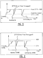
- Figures 1 and 2 illustrate how EFTR and ETR are related in SHINE only and SHINE+REIN situations respectively.
- the EFTR equals NDR because no overhead is used.
- impulse noise bursts three situations may arise:
- Figure 2 describes a situation where SHINE and REIN events are both present.
- the only difference with the SHINE only situation is that REIN events require a constant amount of retransmissions. Hence, even when there is no SHINE event, the EFTR is below the NDR.
- Figures 1 and 2 show that the typical noise conditions that a line will have to handle must be known in advance in order to correctly configure Shineratio and minINP_REIN to obtain a correct ETR. Obviously, noise is usually not known a priori. Hence, a dynamic reconfiguration method is desirable.
- Dynamic Line Management is a process enabling automatic monitoring and reconfiguration of DSL lines.
- DLM methods include two steps: performance monitoring and reconfiguration.
- Performance monitoring typically comprises monitoring line performance and line stability.
- Line performance is monitored during a given period of typically one or several days.
- Monitored line performance parameters can include actual data rates, number of transmission errors, number of resynchronizations, noise level, etc.
- Line stability is usually measured by counting the number of CPE spontaneous resynchronizations and the number of transmission errors, i.e. the number of Coding Violations (CVs).
- the metrics used are often the Mean Time Between Resynchronization (MTBR) and the Mean Time Between Errors (MTBE).
- the MTBE can be defined in different ways, depending on what is considered to be a transmission error.
- the MTBR or MTBE can be obtained e.g.
- the noise margin could be measured as another metric that is representative for the stability of the line.
- the MTBR is usually preferred as this is a metric that is directly related to what the customers experience.
- a bad MTBR is often an indication that the stationary noise level may sometimes become higher than the available noise margin.
- a solution is to increase the available noise margin by reducing the bit rate at which the line synchronizes.
- a bad MTBE is usually an indication that the line is affected by impulse noise. This problem can be addressed by increasing the level of INP.
- a line reconfiguration may be performed. If during the monitoring period it is noticed that line performance can be improved, a reconfiguration request is sent to the DSLAM.
- This reconfiguration can take different aspects. For instance, it can comprise switching configuration profiles of the line, where the candidate profiles are chosen within a predefined set of profiles. In other systems, the reconfiguration can comprise reconfiguring one or several parameters of the lines independently.
- Embodiments of the method typically comprise the configuration of retransmission parameters affecting line stability, as well as the configuration of retransmission parameters affecting data rate (ETR) reporting, typically without having an impact on the stability.
- ERR data rate
- Embodiments of the invention are based inter alia on the insight that the retransmission parameters influencing the line stability are maxNDR representing the maximum Net Data Rate and maxDelay representing the maximum delay allowed for retransmissions.
- the parameter maxNDR is used to limit the bit rate at which the line can synchronize, and as a consequence to increase the available noise margin. Hence, this parameter will mainly impact the MTBR. To maximize performance, the maxNDR should be as high as possible, but to keep a sufficient noise margin and to limit the probability of resynchronization in case of variation of the stationary noise level, the maxNDR may not be too high.
- the parameter maxDelay is used to increase the effective INP, and represents the maximum delay allowed for retransmitting DTUs corrupted by impulse noise. Hence, the higher this maximum delay, the more data can be retransmitted and therefore, the higher the INP protection. Therefore, this parameter will mainly impact the MTBE.
- the drawback of increasing maxDelay is that it increases the potential jitter in upper layer data streams. Indeed, the actual transmission delay is not constant. It varies between the configured minDelay, when no retransmission is needed, to maxDelay when the maximum amount of allowed retransmissions is required. So, in order to limit the potential jitter, maxDelay should be configured as low as possible while maintaining a sufficient MTBE.
- maxDelay is correlated with minINP_SHINE.
- maxDelay provides the CPE/DSLAM with an upper limit for the INP level that can be choosen, while minINP_SHINE providers a lower limit for the INP level against SHINE.
- minINP_SHINE instead of using maxDelay, it is also possible to use minINP_SHINE as a line stability parameter representative for a delay allowed for retransmitting DTUs. If minINP_SHINE is varied maxDelay is preferably also changed in order to avoid synchronization problems, because minINP_SHINE puts a lower bound on the allowed values of maxDelay.
- Embodiments of the invention are based inter alia on the insight that the retransmission parameters influencing ETR reporting comprise Shineratio, i.e. the expected percentage of NDR needed for retransmitting DTUs corrupted by SHINE events; minINP_REIN, i.e. the expected maximum number of consecutive DMT symbols corrupted by REIN events; and maxETR, i.e. the maximum allowed ETR.
- Shineratio i.e. the expected percentage of NDR needed for retransmitting DTUs corrupted by SHINE events
- minINP_REIN i.e. the expected maximum number of consecutive DMT symbols corrupted by REIN events
- maxETR i.e. the maximum allowed ETR.
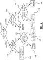
- Preferred embodiments of the invention comprise an optimizing module 300 combining bit rate optimization 302 with INP optimisation 303 and ETR optimization 304, see Figure 3 .
- the invention also encompasses optimization methods and systems comprising only one, or two of the three optimizations mentioned above.
- Through monitoring and obtaining module 301 a number of metrics is obtained.
- any combination of optimizations 302, 303, 304 is performed, resulting in one or more changed retransmission parameters, whereupon the line is reconfigured by a reconfiguring module 305.
- Embodiments of the method can be a part of a DLM engine for the automatic monitoring and reconfiguration of DSL lines.
- the line being optimized can be constantly under monitoring by module 301, i.e. operational parameters are collected on a regular basis and stability metrics are regularly computed.
- Bit rate or NDR optimization 302 typically uses the MBTR metric obtained through the monitoring module 301. This optimization comprises pushing the parameter NDR as high as possible while maintaining an acceptable level for the MTBR, i.e. MTBR should be higher than a minimum preconfigured threshold. If MTBR is below the minimum threshold configured by the operator, NDR is reduced until MTBR increases to an acceptable level.
- the bit rate optimization results in a value for the maximum Net Data Rate (maxNDR) corresponding to the maximum allowed bit rate, i.e. the maximum bit rate allowed by an operator.
- maxNDR maximum Net Data Rate
- Several state of the art methods can be used in DLM systems to optimize the bit rate, from the simplest trial and error approach to more advanced techniques including the computation of theoretically achievable line performance (theoretical bit rate), based on the estimation of noise conditions.
- the INP level optimization 303 typically uses the MTBE metric obtained through the monitoring module 301, and may comprise finding the minimum level of INP required to get an MTBE above a given preconfigured threshold, as required by the operator.
- the level of INP is related to the maximum amount of delay allowed for retransmissions. Therefore, a preferred INP level optimization comprises automatically incrementing the maxDelay parameter until the observed MTBE is higher than the preconfigured threshold.
- the maxDelay should have a value higher than or equal to the RTT. If maxDelay equals the RTT, each DTU could be retransmitted only once. In such a case, if a retransmitted DTU gets corrupted again, there is no time left for another retransmission and this DTU will be discarded, leading to transmission errors. Based on those considerations, maxDelay is preferably optimized such that it has a value corresponding to multiples of the RTT in order to enable multiple retransmissions. For DSL lines with tones spacing of 4.3125 kHz, the RTT is expected to lie between 4-5 ms. In the following, as an example, a conservative approach is followed assuming that the RTT is 6 ms.
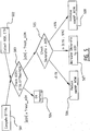
- a method for optimizing maxDelay is depicted in Figure 4 and explained hereafter.
- maxDelay is set to a value of 1 * RTT, see step 403. If maxDelay is larger than or equal to RTT, but below a (MAX - RTT), where MAX is a threshold configured by the operator, maxDelay is increased by a further step of 6 ms, see steps 404 and 405. If maxDelay in step 404 is larger than (MAX - RTT), NDR is reduced, see step 406.
- maxDelay is first set to RTT, and if, after reconfiguration, MTBE is still below minMBTE, the maxDelay will be increased by steps of 6ms, as long as the maximum delay allowed by the operator (MAX) is not reached. In case the maximum allowed delay (MAX) is reached and MTBE is still too low, the only remaining solution consists in reducing the Net Data Rate (maxNDR), which will correspondingly increase the available noise margin, and hopefully mitigate the impulse noise effect.
- MAX maximum allowed delay allowed by the operator
- maxNDR Net Data Rate
- a step 407 it is verified if the current maxDelay has a value larger than or equal to 2* RTT. If that is the case, implying that the INP level is sufficient, maxDelay is reduced by RTT, unless reducing maxDelay has already been tried in a previous iteration of the method, see steps 409 and 410. If reducing maxDelay has already been tried in a previous iteration of the method and yielded an insufficient MTBE, nothing is done, see step 411, since the optimal configuration of maxDelay is achieved. If maxDelay is larger than or equal to 2 * RTT, the optimization is stopped and no reconfiguration of the maxDelay parameter is performed, see step 408. Reducing the maxDelay when it is at least 2 * RTT may have the advantage that the potential jitter in the upper transmission layers can be minimized.
- the proposed exemplary INP optimization method is an iterative process. So, reconfigurations are based on the line performance metrics observed over the past one or several monitoring periods. As long as previously tested configurations and their outcome (effect on stability) are remembered - since those are required for step 409 -, the exemplary optimization process of Figure 4 will eventually converge towards the optimal configuration of maxDelay.
- the proposed method of Figure 4 is exemplary, and that other variants are possible.
- the maxDelay could directly be configured at its maximum value allowed by the operator (MAX). Then, gradually decreasing values could be tested, instead of testing gradually increasing values.
- ETR optimization 304 can be split in two sub-steps. The first one comprises evaluating the EFTR of the line, and the second step comprises tuning the retransmission parameters to get the ETR as close as possible to the observed EFTR.
- the EFTR can be evaluated in different ways. If an operator considers the ETR as the minimum guaranteed bit rate that should be available for user traffic, then its reported value should be close to the smallest EFTR observed during the monitoring period. In such a case, the minEFTR values reported during the observation interval could be considered. On the other hand, if an operator considers the ETR as an average bit rate that should be available for user traffic, then its reported value should be close to the average EFTR observed during the monitoring period. So, the EFTR could be computed from the EFbits counter.
- FIG. 5 An exemplary method for optimization of parameters affecting the ETR reporting and is depicted in Figure 5 .
- EFTR Error-Free Throughput
- a first step 501 an estimation of the Error-Free Throughput (EFTR), defined as EFTRe in Figure 5 .
- the two retransmission parameters "Shineratio" and “minINP_REIN” are optimized in order to match the ETR as closely as possible to the EFTRe, see steps 503-508, using the metrics NDR and ETR obtained through monitoring, see step 502.
- the EFTR is not directly reported, but can be estimated, for instance by using an Error-Free bits counter (EFbits) or a minimum EFTR value (minEFTR), depending on whether the operator wants the ETR to represent the average achievable EFTR or the minimum guaranteed EFTR.
- An EFbits counter counts the number of bits transmitted flawlessly over a given period of time. The value of this counter can be retrieved periodically during monitoring and divided by the period duration. This provides an estimation of the average EFTR observed during each observation interval. Then it is possible to compute a probability distribution of the observed EFTR and compute EFTRe, for instance as the average value or the xx% worst case.
- a minEFTR value represents the minimum EFTR values observed over a given period of time (for example 15 min, or 1 hour). By collecting the minEFTR values periodically, the value below which the EFTR never drops can be determined and used as EFTRe. In order to avoid making computations based on a very low EFTRe (close to zero) that happens only rarely during very strong bursts of noise, one could for instance, discard the worst or two worst values.
- step 503 the absolute value of this overhead correction ⁇ OH is first compared to a preconfigured threshold Tresh_ ⁇ OH, and the optimization (steps 504-508) is only performed if the correction is higher than Tresh_ ⁇ OH.
- the purpose of this test is to avoid continuous oscillations of the configuration when ETR is already close to EFTRe.
- a typical value for Thresh_OH is around 2 to 5%. A lower value would increase the final ETR accuracy, but would simultaneously increase the probability of oscillations.
- the currently configured Shineratio is corrected with ⁇ OH, as long as the resulting value lies within the allowed range, typically from 0.1% to 10%, see the discussion above about the Shineratio. If the resulting Shineratio would be higher than 10%, this probably means that some REIN is affecting the transmission, and the solution is to first increase minINP_REIN, see step 508. If the correction is below 0.1%, including negative values, this means that minINP_REIN is configured at a too high value and should be decreased, see step 506.
- the exemplary method depicted in Figure 5 must be seen as an iterative process, and the computations performed during each iteration may be based on one or several previous monitoring periods.
- the optimal configuration is expected to be achieved in only one iteration.
- minINP_REIN must be tuned, as the exact amount of overhead introduced by the minINP_REIN setting is not a priori known, an additional iteration may be necessary to adapt the Shineratio value.
- a "Low Error-Free Throughput Seconds” (LEFTRS) counter may be taken into account when an overhead correction is positive, see step 607, in order to avoid some potentially undesirable reconfigurations.
- LFTRS Low Error-Free Throughput Seconds
- a "Low Error-Free Throughput” event is flagged when the EFTR, averaged over one second, is below a given threshold.
- a LEFTRS counter counts those events that occurred over a given period of time. The default threshold lies at 0.998*ETR, but can be reconfigured as a fraction of NDR.
- the LEFTRS counter is a measure for the amount of time the LEFTR was below the ETR. With that knowledge, an operator may decide that having the LEFTR below the ETR for only a small fraction of time would be acceptable. Hence, a reconfiguration would only be triggered if the LEFTR was below the ETR during a significant (configurable) fraction of the monitoring time, see steps 607-611.
- LEFTR_Time is the minimum fraction of time with LEFTR ⁇ ETR required to trigger a reconfiguration. The fraction of time where LEFTR was below ETR can be estimated by the ratio LEFTR/Period, where "Period" is the period of time within which the LEFTRS counter has been observed.
- bit rate optimization, INP optimization and ETR optimization may be done independently or in parallel.
- bit rate optimization, INP optimization and ETR optimization may be done independently or in parallel.
- the MTBR could be checked.
- a possibility would be to optimize first maxNDR, optionally in parallel with an ETR optimization, followed by a reconfiguration, and then to optimize the INP level.
- optimizing the bit rate and the INP level could be done in parallel, optionally further in parallel with an ETR optimization, followed by a reconfiguration.
- first a bit rate optimization may be performed.
- bit rate optimization may be followed by an INP level optimization and an ETR optimization which may be performed in parallel.
- embodiments of the method and system of the invention enable the automatic configuration of parameters related to the error correction capability, as well as those related to the effective data rate estimation.
- the proposed method can easily be implemented as a DLM system, or at least as a part of a DLM system.
- Embodiments of the method of the invention can be seen as a DLM method dedicated to retransmission line parameters.
- the proposed methods can be used as standalone procedures or they can be implemented as a part of more general DLM engines.
- program storage devices e.g., digital data storage media, which are machine or computer readable and encode machine-executable or computer-executable programs of instructions where said instructions perform some or all of the steps of methods described herein.
- the program storage devices may be, e.g., digital memories, magnetic storage media such as a magnetic disks or tapes, hard drives, or optically readable digital data storage media.
- the embodiments are also intended to cover computers programmed to perform said steps of methods described herein.
Landscapes
- Engineering & Computer Science (AREA)
- Quality & Reliability (AREA)
- Computer Networks & Wireless Communication (AREA)
- Signal Processing (AREA)
- Physics & Mathematics (AREA)
- Probability & Statistics with Applications (AREA)
- Detection And Prevention Of Errors In Transmission (AREA)
Description
- Embodiments of the invention relate to the field of physical layer retransmission, and in particular to the field of configuring physical layer retransmission parameters.
- Nowadays, many DSL operators and service providers resort to automated dynamic line management (DLM) systems. These systems enable an automatic reconfiguration of DSL lines, depending on observed line performance and possibly varying noise environment. Typically, line performance (achieved bitrate, ...) and stability (number of resynchronizations, transmission errors) are observed during a given period of time, and the line is reconfigured in the event that the performance or stability can be increased. This reconfiguration can be performed either by configuring new profiles (containing all configuration parameters), or by reconfiguring one or several of these configuration parameters separately.
- Although the automatic reconfiguration of parameters is known, there does not exist a suitable method for the automatic reconfiguration of physical layer retransmission parameters related to Impulse Noise Protection (INP).
- Traditionally, DSL lines are protected against impulse noise by resorting to a Forward Error Correction + Interleaver (IFEC) mechanism, consisting in using Reed-Solomon (RS) codewords and a data interleaver. The configuration of the required level of INP is relatively easy, as only two parameters are involved: minINP, representing the minimum number of consecutive symbols that can be corrected; and maxDelay representing the maximum delay allowed for the interleaver. The values for these two parameters cannot be chosen totally independently, because some constraints apply on the INP/Delay ratio. Hence, the number of possible IFEC configurations is relatively limited, and automated IFEC reconfiguration on DSL lines can be carried out by existing techniques. However, a drawback of the IFEC mechanisms is that this type of INP is constantly consuming bandwidth. Indeed, the RS coding adds some data overhead that must be transmitted with user data, which can significantly reduce the effective data rate available for user traffic, especially when a high level of INP is required.
- Recently, DSL service providers have started testing and deploying a new standard technique for improved protection against impulse noise. This technique is following the ITU-T G.998.4 standard and is also known as G.INP, RTX, or Automatic Repeat Query (ARQ). It consists in a retransmission mechanism at physical layer level. An advantage of RTX versus IFEC lies in the fact that the bit rate overhead needed for data retransmission is only used when necessary. This implies that when impulse noise level is low, and retransmission is not required, no overhead is used and the full net data rate is available for user traffic. However, RTX has the drawback that a good configuration is not straightforward in view of the many configuration parameters and the fact that the effective data rate available for user traffic is not constant because it depends on the amounts of retransmissions needed. Apparatuses and methods for improving communication are known from
US6718493 ,US2009/177938 ,US2013/021931 andEP2068481 . - The object of embodiments of the present invention is to provide a method and a system capable of dealing in an efficient and robust way with the automatic configuration of configuration parameters for use in a retransmission method at the physical level, and in particular a new method and system for the automated dynamic reconfiguration of retransmission parameters for a physical layer retransmission method for enhancing impulse noise protection.
- Preferred embodiments of the invention enable the automatic configuration of parameters related to the error correction capability, as well as those related to the effective data rate estimation.
- According to an embodiment of the invention there is provided a method for automatic reconfiguration of physical layer retransmission parameters associated with a line, for enhanced impulse noise protection. The method comprises monitoring line performance of the line and obtaining at least one metric representative for impulse noise based on the monitoring; optimizing at least one physical layer retransmission parameter, based on the at least one metric; and reconfiguring the at least one physical layer retransmission parameter of the line.
- By obtaining suitable impulse noise metrics through monitoring, the physical layer retransmission parameters can be automatically reconfigured, so that the retransmission can be performed in an optimal way at all times.
- The at least one physical layer retransmission parameter preferably comprises at least two line stability parameters including a delay parameter representative for the delay allowed for retransmission of a data packet and a data rate parameter representative for the data rate at which the line can synchronize. If those two parameters are optimized the stability of the line can be guaranteed, also in case of a varying INP events.
- Preferably monitoring the line performance comprises monitoring the errors and resynchronizations on the line. The at least one obtained metric comprises preferably an error metric representative for the number of errors per unit of time and/or a resynchronization metric representative for the number of resynchronizations per unit of time. E.g. the error metric may be a mean time between errors (MTBE) calculated by dividing an observation interval duration by a monitored number of code violations. E.g. the resynchronization metric may be a mean time between resynchronizations (MTBR) calculated by dividing an observation interval duration by a monitored number of resynchronizations. The error and resynchronization metrics correspond directly to problems observed by the user, and allow for a good optimization of the physical layer retransmission parameters.
- Preferably the optimizing comprises increasing/decreasing the delay parameter and/or increasing/decreasing the data rate parameter. Preferably the monitoring, optimizing and reconfiguring are repeated until the error metric is above a predefined threshold and the resynchronization parameter is above a predefined threshold.
- Preferably the delay parameter is a maximum delay parameter indicating a maximum delay allowed for retransmissions. Alternatively the delay parameter may be a Single High Impulse Noise Environment (SHINE) parameter indicating an expected number of consecutive DMT symbols affected by SHINE, e.g. minINP_SHINE as defined below. The data rate parameter is preferably a maximum net data rate parameter, e.g. maxNDR as defined below, indicating a maximum net data rate at which the line can synchronize.
- Preferably, optimizing the delay parameter comprises decreasing or increasing the delay parameter with an amount equal to the round trip time or a multiple thereof, and/or setting the delay parameter to the round trip time or a multiple thereof. The round trip time corresponds with the time needed to issue a retransmission request of a data transmission unit and to retransmit the requested data transmission unit. For that reason the allowed delay between retransmissions is preferably a multiple of the round trip time (RTT).
- According to a preferred embodiment monitoring the line performance further comprises measuring parameters suitable for estimating an error-free throughput metric representative for the net data rate minus the data rate needed for retransmissions. Suitable parameters are e.g. an error-free bits counter or a minimum error-free throughput value. The error-free throughput metric is computed using the measured parameters. Further the monitoring may comprise collecting metrics representative for the net data rate and the expected throughput (the net data rate minus the expected retransmission overhead). Preferably, optimizing the at least one physical layer retransmission parameter comprises optimizing a single high impulse noise environment (SHINE) parameter representative for a duration of SHINE events and/or optimizing a repetitive impulse noise (REIN) parameter representative for a duration of REIN events, based on the computed error-free throughput metric and the collected net data rate and expected throughput. In that way also parameters affecting the expected throughput reporting, without impact on the line stability, are optimized.
- In a preferred embodiment the SHINE parameter indicates an expected amount of overhead necessary for retransmission of DTUs affected by SHINE (e.g. the Shineratio parameter as defined below), and the REIN parameter indicates an expected number of consecutive DMT symbols affected by REIN (e.g. the minINP_REIN parameter as defined below).
- When SHINE and REIN parameters are involved, the optimizing may comprise increasing the SHINE parameter if an absolute value of a difference between the expected throughput and the computed error-free throughput metric is larger than a predefined threshold as long as the SHINE parameter is within a predefined range. Further, the optimizing may comprise increasing the REIN parameter if the SHINE parameter is too high, and decreasing the REIN parameter if the SHINE parameter is too low. In that way the expected throughput can be made to approach the computed error-free throughput as required.
- According to a further aspect of the invention, there is provided a computer device or other hardware device programmed to perform one or more optimizing and/or reconfiguring steps of any one of the embodiments of the method disclosed above. According to another aspect there is provided a data storage device encoding a program in machine-readable and machine-executable form to perform one or more optimizing and/or reconfiguring steps of any one of the embodiments of the method disclosed above.
- According to yet another aspect of the invention there is provided a system for automatic reconfiguration of physical layer retransmission parameters associated with a line, for enhanced impulse noise protection, comprising a monitoring and obtaining module configured for monitoring line performance of the line and for obtaining at least one metric representative for impulse noise based on the monitored line performance; an optimizing module configured for optimizing at least one physical layer retransmission parameter, based on the at least one metric; and a reconfiguring module configured for reconfiguring the at least one physical layer retransmission parameter of the line.
- Preferably the monitoring and obtaining modules is configured for monitoring the transmission errors and/or spontaneous resynchronizations on the line, and for obtaining an error metric representative for the number of errors per unit of time and/or a resynchronization metric representative for the number of resynchronizations per unit of time.
- Preferably, the optimizing module is configured for optimizing at least two line stability parameters including a delay parameter representative for a delay allowed for retransmission of a data packet and a data rate parameter representative for the data rate at which the line can synchronize, wherein the optimizing consists in increasing/decreasing the delay parameter and/or increasing/decreasing the data rate parameter. Preferably the delay parameter is a maximum delay parameter indicating a maximum delay allowed for retransmissions. The data rate parameter is preferably a maximum net data rate parameter indicating a maximum net data rate at which the line can synchronize.
- Preferably, the system further comprises a controller for controlling the monitoring, optimizing and reconfiguring module to repeat the monitoring, optimizing and reconfiguring until the error metric is above a predefined threshold and the resynchronization parameter is above a predefined threshold.
- The optimizing module may be further configured for optimizing the delay parameter by decreasing or increasing the delay parameter with an amount equal to the round trip time or a multiple thereof, and/or by setting the delay parameter to the round trip time or a multiple thereof.
- According to a further developed embodiment the monitoring and obtaining module may be further configured for measuring parameters suitable for estimating an error-free throughput metric representative for the net data rate minus the data rate needed for retransmissions; for computing the error-free throughput metric using said measured parameters; and for collecting metrics representative for the net data rate and the expected throughput being the net data rate minus the expected overhead. The optimizing module may be further configured for optimizing a single high impulse noise environment (SHINE) parameter representative for a duration of SHINE events and/or optimizing a repetitive impulse noise (REIN) parameter representative for a duration of REIN events, based on the computed error-free throughput metric and the collected net data rate and expected throughput. Preferably, the SHINE parameter indicates an expected amount of overhead necessary for retransmission of data transmission units affected by SHINE, and the REIN parameter indicates an expected maximum number of consecutive discrete multi-tone symbols affected by REIN. Typically the optimizing module is adapted for increasing the SHINE parameter if an absolute value of a difference between the expected throughput and the computed error-free throughput metric is larger than a predefined threshold as long as the SHINE parameter is within a predefined range, and/or for increasing the REIN parameter if the resulting SHINE parameter would be too high, and decreasing the REIN parameter if the resulting SHINE parameter would be too low.
- Embodiments of the system or computer program product or computer device of the invention may be implemented as a DLM system, or as a part of a DLM system.
- The accompanying drawings are used to illustrate presently preferred non-limiting exemplary embodiments of methods and systems of the present invention. The above and other advantages of the features and objects of the invention will become more apparent and the invention will be better understood from the following detailed description when read in conjunction with the accompanying drawings, in which:
-
Figure 1 is a graph of the error-free throughput in function of time in a SHINE only environment; -
Figure 2 is a graph of the error-free throughput in function of time in a SHINE + REIN environment; -
Figure 3 illustrates schematically an embodiment of a system and method of the invention; -
Figure 4 is a flow chart illustrating a first embodiment of the method of the invention including INP optimization; -
Figure 5 is a flow chart illustrating a second embodiment of the method of the invention including ETR optimization; and -
Figure 6 is a flow chart illustrating a third embodiment of the method of the invention including ETR optimization. - The standard technique for improved protection against impulse noise, also known as the ITU-T G.998.4 standard, G.INP, RTX, or Automatic Repeat Query (ARQ), consists in a retransmission mechanism at physical layer level. When a packet of data, called Data Transmission Unit (DTU), is corrupted, it can be automatically and seamlessly retransmitted. An advantage of RTX is that the bit rate overhead needed for data retransmission is only used when data retransmission is needed. This implies that when impulse noise level is low, and retransmission is not required, no overhead is used and the full net data rate is available for user traffic. However, RTX has some drawbacks:
- generally many parameters need to be configured to make this technique works efficiently;
- the effective data rate available for user traffic is not constant, because it depends on the amount of needed retransmissions.
- Embodiments of the invention provide a method for the automated dynamic reconfiguration of physical level retransmission parameters.
- To give the reader a better insight in embodiments of the invention, first some concepts of physical level retransmission for enhancing INP and DLM will be recalled.
- The ITU-T G.998.4 standard defines the following variables and configuration parameters:
- Net Data Rate (NDR) representing the total bit rate available on the line when no retransmission occurs. This is the data rate at which the line is synchronized;
- Error-Free Throughput (EFTR) representing the actual data rate available for user traffic. It consists in the NDR minus the overhead needed for retransmissions. When no retransmission occurs, EFTR equals NDR. Hence EFTR will vary depending on impulse noise conditions, and is not directly reported by the management layers;
- minINP_SHINE representing a configuration parameter describing the expected maximum number of consecutive Discrete Multi-Tone (DMT) symbols that could be affected by Single High Impulse Noise Environment (SHINE) events, i.e. isolated bursts of impulse noise. In other words, it describes the minimum level of impulse noise protection (INP) against SHINE events, required for error-free transmission in the expected noise conditions;
- minINP_REIN representing a configuration parameter describing the expected maximum number of consecutive DMT symbols that could be affected by Repetitive Impulse Noise (REIN), i.e. impulse noise occurring at a given rate. This rate can be configured through the Inter-Arrival Time for REIN (IAT_REIN)) parameter and usually corresponds to 100 Hz in Europe and 120 Hz in North America. minINP_REIN then also describes the minimum level of INP against REIN, required for error-free transmission in the expected noise conditions;
- Shineratio (SHINE_OH) representing a configuration parameter describing the amount of overhead that is expected to be necessary for retransmission of corrupted DTUs that have been affected by SHINE. This ratio is given as a percentage of the NDR and can be configured between 0.1% and 10%;
- Retransmission overhead (RTX_OH) representing the proportion of the NDR that is used for retransmission of corrupted DTUs, and which is then not available for user traffic. In the G.INP standard, the expected overhead is computed as follows:

- Expected Throughput (ETR) being computed during modem synchronization and representing the EFTR that would be obtained if noise conditions are exactly requiring the expected amount of overhead, as computed from configured Shineratio and minINP_REIN. ETR is computed as follows:

- minEFTR reporting the minimum EFTR observed over a given observation interval, e.g. 15 min., 1 hour, 1 day, etc. The considered EFTR is the averaged value over 1 second window;
- EFbits representing a counter of the number of Error-Free bits transmitted during a given observation interval. By dividing the increase of this counter over an observation interval by the duration of this interval, an estimation of the average EFTR achieved over this interval is obtained.
-
Figures 1 and 2 illustrate how EFTR and ETR are related in SHINE only and SHINE+REIN situations respectively. As illustrated inFigure 1 , in a SHINE only environment, when no retransmission is needed, the EFTR equals NDR because no overhead is used. In case of impulse noise bursts, three situations may arise: - a "Friendly impulse noise (IN)" situation where the burst is short enough so that the overhead needed for retransmissions is lower than the configured Shineratio; in that case the EFTR will drop during the retransmissions but remains above the ETR.
- a ."Nominal IN" situation where the burst is longer and requires an amount of overhead that exactly matches the configured Shineratio; in that case the EFTR drops at ETR level during the retransmissions.
- a "Unfriendly IN" situation where the burst is so long that the overhead provision is not sufficient; in that case the EFTR will drop below the ETR during the retransmissions.
-
Figure 2 describes a situation where SHINE and REIN events are both present. The only difference with the SHINE only situation is that REIN events require a constant amount of retransmissions. Hence, even when there is no SHINE event, the EFTR is below the NDR. -
Figures 1 and 2 show that the typical noise conditions that a line will have to handle must be known in advance in order to correctly configure Shineratio and minINP_REIN to obtain a correct ETR. Obviously, noise is usually not known a priori. Hence, a dynamic reconfiguration method is desirable. - Dynamic Line Management (DLM) is a process enabling automatic monitoring and reconfiguration of DSL lines. DLM methods include two steps: performance monitoring and reconfiguration.
- Performance monitoring typically comprises monitoring line performance and line stability. Line performance is monitored during a given period of typically one or several days. Monitored line performance parameters can include actual data rates, number of transmission errors, number of resynchronizations, noise level, etc. Line stability is usually measured by counting the number of CPE spontaneous resynchronizations and the number of transmission errors, i.e. the number of Coding Violations (CVs). The metrics used are often the Mean Time Between Resynchronization (MTBR) and the Mean Time Between Errors (MTBE). The MTBE can be defined in different ways, depending on what is considered to be a transmission error. The MTBR or MTBE can be obtained e.g. by dividing the observation interval duration by the number of spontaneous resynchronizations or by the number of CVs that occurred during this interval, respectively. As an alternative, instead of monitoring the MTBR, the noise margin could be measured as another metric that is representative for the stability of the line. However, the MTBR is usually preferred as this is a metric that is directly related to what the customers experience. A bad MTBR is often an indication that the stationary noise level may sometimes become higher than the available noise margin. In order to increase the MTBR, a solution is to increase the available noise margin by reducing the bit rate at which the line synchronizes. On the other hand, a bad MTBE is usually an indication that the line is affected by impulse noise. This problem can be addressed by increasing the level of INP.
- Based on the monitored performance a line reconfiguration may be performed. If during the monitoring period it is noticed that line performance can be improved, a reconfiguration request is sent to the DSLAM. This reconfiguration can take different aspects. For instance, it can comprise switching configuration profiles of the line, where the candidate profiles are chosen within a predefined set of profiles. In other systems, the reconfiguration can comprise reconfiguring one or several parameters of the lines independently.
- Taking into account the insights regarding the retransmission concepts and DLM concepts described above, embodiments of the invention will now be described in more detail. Embodiments of the method typically comprise the configuration of retransmission parameters affecting line stability, as well as the configuration of retransmission parameters affecting data rate (ETR) reporting, typically without having an impact on the stability.
- Embodiments of the invention are based inter alia on the insight that the retransmission parameters influencing the line stability are maxNDR representing the maximum Net Data Rate and maxDelay representing the maximum delay allowed for retransmissions.
- The parameter maxNDR is used to limit the bit rate at which the line can synchronize, and as a consequence to increase the available noise margin. Hence, this parameter will mainly impact the MTBR. To maximize performance, the maxNDR should be as high as possible, but to keep a sufficient noise margin and to limit the probability of resynchronization in case of variation of the stationary noise level, the maxNDR may not be too high.
- The parameter maxDelay is used to increase the effective INP, and represents the maximum delay allowed for retransmitting DTUs corrupted by impulse noise. Hence, the higher this maximum delay, the more data can be retransmitted and therefore, the higher the INP protection. Therefore, this parameter will mainly impact the MTBE. The drawback of increasing maxDelay is that it increases the potential jitter in upper layer data streams. Indeed, the actual transmission delay is not constant. It varies between the configured minDelay, when no retransmission is needed, to maxDelay when the maximum amount of allowed retransmissions is required. So, in order to limit the potential jitter, maxDelay should be configured as low as possible while maintaining a sufficient MTBE.
- It is noted that maxDelay is correlated with minINP_SHINE. maxDelay provides the CPE/DSLAM with an upper limit for the INP level that can be choosen, while minINP_SHINE providers a lower limit for the INP level against SHINE. Hence, instead of using maxDelay, it is also possible to use minINP_SHINE as a line stability parameter representative for a delay allowed for retransmitting DTUs. If minINP_SHINE is varied maxDelay is preferably also changed in order to avoid synchronization problems, because minINP_SHINE puts a lower bound on the allowed values of maxDelay.
- Embodiments of the invention are based inter alia on the insight that the retransmission parameters influencing ETR reporting comprise Shineratio, i.e. the expected percentage of NDR needed for retransmitting DTUs corrupted by SHINE events; minINP_REIN, i.e. the expected maximum number of consecutive DMT symbols corrupted by REIN events; and maxETR, i.e. the maximum allowed ETR.
- Preferred embodiments of the invention comprise an optimizing
module 300 combiningbit rate optimization 302 withINP optimisation 303 andETR optimization 304, seeFigure 3 . However, the invention also encompasses optimization methods and systems comprising only one, or two of the three optimizations mentioned above. Through monitoring and obtaining module 301 a number of metrics is obtained. Using the obtained metrics any combination ofoptimizations reconfiguring module 305. - Embodiments of the method can be a part of a DLM engine for the automatic monitoring and reconfiguration of DSL lines. Hence, the line being optimized can be constantly under monitoring by
module 301, i.e. operational parameters are collected on a regular basis and stability metrics are regularly computed. - Bit rate or
NDR optimization 302 typically uses the MBTR metric obtained through themonitoring module 301. This optimization comprises pushing the parameter NDR as high as possible while maintaining an acceptable level for the MTBR, i.e. MTBR should be higher than a minimum preconfigured threshold. If MTBR is below the minimum threshold configured by the operator, NDR is reduced until MTBR increases to an acceptable level. Preferably, the bit rate optimization results in a value for the maximum Net Data Rate (maxNDR) corresponding to the maximum allowed bit rate, i.e. the maximum bit rate allowed by an operator. Several state of the art methods can be used in DLM systems to optimize the bit rate, from the simplest trial and error approach to more advanced techniques including the computation of theoretically achievable line performance (theoretical bit rate), based on the estimation of noise conditions. - The
INP level optimization 303 typically uses the MTBE metric obtained through themonitoring module 301, and may comprise finding the minimum level of INP required to get an MTBE above a given preconfigured threshold, as required by the operator. The level of INP is related to the maximum amount of delay allowed for retransmissions. Therefore, a preferred INP level optimization comprises automatically incrementing the maxDelay parameter until the observed MTBE is higher than the preconfigured threshold. - When a transmitted DTU was corrupted, a request is sent from the receiver to the transmitter to send again this DTU. The time needed to issue this request and retransmit the DTU is called the "Round Trip Time" (RTT). Hence, preferably the maxDelay should have a value higher than or equal to the RTT. If maxDelay equals the RTT, each DTU could be retransmitted only once. In such a case, if a retransmitted DTU gets corrupted again, there is no time left for another retransmission and this DTU will be discarded, leading to transmission errors. Based on those considerations, maxDelay is preferably optimized such that it has a value corresponding to multiples of the RTT in order to enable multiple retransmissions. For DSL lines with tones spacing of 4.3125 kHz, the RTT is expected to lie between 4-5 ms. In the following, as an example, a conservative approach is followed assuming that the RTT is 6 ms.
- An example of a method for optimizing maxDelay is depicted in
Figure 4 and explained hereafter. In afirst step 401 it is verified if the MBTE obtained through monitoring is smaller than a predefined threshold minMTBE. Two situations may arise. Either the actual MTBE is sufficiently high (>= minMBTE), implying a sufficient INP protection level, or the actual MTBE is too low (< minMBTE), implying an INP level which is not sufficient. - When the MTBE is smaller than minMBTE, in a
step 402 it is verified if the current maxDelay has a value below RTT (assumed to be 6 ms). If that is the case, which implies that there is virtually no INP, maxDelay is set to a value of 1 * RTT, seestep 403. If maxDelay is larger than or equal to RTT, but below a (MAX - RTT), where MAX is a threshold configured by the operator, maxDelay is increased by a further step of 6 ms, seesteps step 404 is larger than (MAX - RTT), NDR is reduced, seestep 406. - In other words, if MTBE is smaller than minMBTE and maxDelay is smaller than RTT, maxDelay is first set to RTT, and if, after reconfiguration, MTBE is still below minMBTE, the maxDelay will be increased by steps of 6ms, as long as the maximum delay allowed by the operator (MAX) is not reached. In case the maximum allowed delay (MAX) is reached and MTBE is still too low, the only remaining solution consists in reducing the Net Data Rate (maxNDR), which will correspondingly increase the available noise margin, and hopefully mitigate the impulse noise effect.
- When the MTBE is larger than or equal to minMBTE, in a
step 407 it is verified if the current maxDelay has a value larger than or equal to 2* RTT. If that is the case, implying that the INP level is sufficient, maxDelay is reduced by RTT, unless reducing maxDelay has already been tried in a previous iteration of the method, seesteps step 411, since the optimal configuration of maxDelay is achieved. If maxDelay is larger than or equal to 2 * RTT, the optimization is stopped and no reconfiguration of the maxDelay parameter is performed, seestep 408. Reducing the maxDelay when it is at least 2 * RTT may have the advantage that the potential jitter in the upper transmission layers can be minimized. - The proposed exemplary INP optimization method is an iterative process. So, reconfigurations are based on the line performance metrics observed over the past one or several monitoring periods. As long as previously tested configurations and their outcome (effect on stability) are remembered - since those are required for step 409 -, the exemplary optimization process of
Figure 4 will eventually converge towards the optimal configuration of maxDelay. - It should be noted that the proposed method of
Figure 4 is exemplary, and that other variants are possible. For instance in case of a bad MTBE, in order to try stabilizing the line as quickly as possible, the maxDelay could directly be configured at its maximum value allowed by the operator (MAX). Then, gradually decreasing values could be tested, instead of testing gradually increasing values. -
ETR optimization 304 can be split in two sub-steps. The first one comprises evaluating the EFTR of the line, and the second step comprises tuning the retransmission parameters to get the ETR as close as possible to the observed EFTR. Depending on the operator's needs, the EFTR can be evaluated in different ways. If an operator considers the ETR as the minimum guaranteed bit rate that should be available for user traffic, then its reported value should be close to the smallest EFTR observed during the monitoring period. In such a case, the minEFTR values reported during the observation interval could be considered. On the other hand, if an operator considers the ETR as an average bit rate that should be available for user traffic, then its reported value should be close to the average EFTR observed during the monitoring period. So, the EFTR could be computed from the EFbits counter. - Once the EFTR has been estimated, the second sub-step then consists in tuning the retransmission parameters to get the reported ETR as close as possible to the computed EFTR. From the estimated EFTR, the overhead that was needed for retransmitting DTUs can be estimated, using

- According to the G.INP standard, this overhead is computed in terms of retransmission configuration parameters as follows:


- Knowing that Shineratio can be configured between 0.1% and 10%, the optimal retransmission configuration parameters can be obtained as follows:
- if computed RTX_OH <= 10%, set Shineratio = RTX_OH and minINP_REIN = 0
- if computed RTX_OH > 10%, iteratively increase minINP_REIN until the remaining overhead is below 10%, then set Shineratio at a value corresponding to the remaining overhead.
- An exemplary method for optimization of parameters affecting the ETR reporting and is depicted in
Figure 5 . In afirst step 501 an estimation of the Error-Free Throughput (EFTR), defined as EFTRe inFigure 5 , is computed. Then, the two retransmission parameters "Shineratio" and "minINP_REIN" are optimized in order to match the ETR as closely as possible to the EFTRe, see steps 503-508, using the metrics NDR and ETR obtained through monitoring, seestep 502. - The EFTR is not directly reported, but can be estimated, for instance by using an Error-Free bits counter (EFbits) or a minimum EFTR value (minEFTR), depending on whether the operator wants the ETR to represent the average achievable EFTR or the minimum guaranteed EFTR. An EFbits counter counts the number of bits transmitted flawlessly over a given period of time. The value of this counter can be retrieved periodically during monitoring and divided by the period duration. This provides an estimation of the average EFTR observed during each observation interval. Then it is possible to compute a probability distribution of the observed EFTR and compute EFTRe, for instance as the average value or the xx% worst case. A minEFTR value represents the minimum EFTR values observed over a given period of time (for example 15 min, or 1 hour). By collecting the minEFTR values periodically, the value below which the EFTR never drops can be determined and used as EFTRe. In order to avoid making computations based on a very low EFTRe (close to zero) that happens only rarely during very strong bursts of noise, one could for instance, discard the worst or two worst values.
- Now the optimization of the two retransmission parameters "Shineratio" and "minINP_REIN" is discussed, see steps 503-508. The purpose of this process is to get the ratio EFTRe/ETR as close to one as possible. If the observed ratio is below one, this means that the RTX overhead (RTX_OH) is underestimated and hence, the ETR is overestimated. If this ratio is above one, the RTX_OH is overestimated and the ETR underestimated. Once the EFTRe is known, the real observed overhead RTX_OH_obs can be calculated and compared to the overhead expected from retransmission configuration RTX_OH_exp. The observed overhead can be estimated by:

- The expected overhead can be calculated as:

- Their difference is the overhead correction that should be applied to get ETR = EFTRe:

- In
step 503 the absolute value of this overhead correction ΔOH is first compared to a preconfigured threshold Tresh_ΔOH, and the optimization (steps 504-508) is only performed if the correction is higher than Tresh_ΔOH. The purpose of this test is to avoid continuous oscillations of the configuration when ETR is already close to EFTRe. A typical value for Thresh_OH is around 2 to 5%. A lower value would increase the final ETR accuracy, but would simultaneously increase the probability of oscillations. - If the required overhead correction is sufficiently large to trigger a reconfiguration, the most direct way of controlling the overhead is through the tuning of Shineratio, see
step 507. In the exemplary embodiment ofFigure 5 the currently configured Shineratio is corrected with ΔOH, as long as the resulting value lies within the allowed range, typically from 0.1% to 10%, see the discussion above about the Shineratio. If the resulting Shineratio would be higher than 10%, this probably means that some REIN is affecting the transmission, and the solution is to first increase minINP_REIN, seestep 508. If the correction is below 0.1%, including negative values, this means that minINP_REIN is configured at a too high value and should be decreased, seestep 506. - Again, the exemplary method depicted in
Figure 5 must be seen as an iterative process, and the computations performed during each iteration may be based on one or several previous monitoring periods. When only the Shineratio needs to be adapted, the optimal configuration is expected to be achieved in only one iteration. In cases where minINP_REIN must be tuned, as the exact amount of overhead introduced by the minINP_REIN setting is not a priori known, an additional iteration may be necessary to adapt the Shineratio value. - It should be noted that the proposed method of
Figure 5 is merely exemplary, and that other variants are possible. According to a variant illustrated inFigure 6 , two different overhead thresholds Thresh_ΔOH_pos and Thresh_ΔOH_neg are used, seestep 603.Steps steps steps step 607, in order to avoid some potentially undesirable reconfigurations. According to the G.INP standard, a "Low Error-Free Throughput" event is flagged when the EFTR, averaged over one second, is below a given threshold. A LEFTRS counter counts those events that occurred over a given period of time. The default threshold lies at 0.998*ETR, but can be reconfigured as a fraction of NDR. Considering the default threshold, the LEFTRS counter is a measure for the amount of time the LEFTR was below the ETR. With that knowledge, an operator may decide that having the LEFTR below the ETR for only a small fraction of time would be acceptable. Hence, a reconfiguration would only be triggered if the LEFTR was below the ETR during a significant (configurable) fraction of the monitoring time, see steps 607-611. LEFTR_Time is the minimum fraction of time with LEFTR < ETR required to trigger a reconfiguration. The fraction of time where LEFTR was below ETR can be estimated by the ratio LEFTR/Period, where "Period" is the period of time within which the LEFTRS counter has been observed. - As previously mentioned, in order to minimize jitter in the applicative layers, the maxDelay is optimized to be as low as possible, while keeping the MTBE at an acceptable level. It is further possible to limit the jitter to an acceptable level configured by the operator, by configuring a minimum allowed delay (minDelay). If, for instance the maximum allowed jitter is "maxJitter", the minDelay could be automatically configured at minDelay = maxDelay - maxJitter, whenever maxDelay is reconfigured.
- Returning to
Figure 3 , it is noted that bit rate optimization, INP optimization and ETR optimization may be done independently or in parallel. E.g. the following scenarios are conceivable. In a first step the MTBR could be checked. In case of a bad MTBR, a possibility would be to optimize first maxNDR, optionally in parallel with an ETR optimization, followed by a reconfiguration, and then to optimize the INP level. Alternatively, in case of a bad MTBR, optimizing the bit rate and the INP level could be done in parallel, optionally further in parallel with an ETR optimization, followed by a reconfiguration. In case of good MBTR, first a bit rate optimization may be performed. In most cases this will not result in a change of the configuration parameters so that in most cases a reconfiguration will not be needed. The bit rate optimization may be followed by an INP level optimization and an ETR optimization which may be performed in parallel. From the examples above it will be understood that embodiments of the method and system of the invention enable the automatic configuration of parameters related to the error correction capability, as well as those related to the effective data rate estimation. Also, the proposed method can easily be implemented as a DLM system, or at least as a part of a DLM system. Embodiments of the method of the invention can be seen as a DLM method dedicated to retransmission line parameters. The proposed methods can be used as standalone procedures or they can be implemented as a part of more general DLM engines. - A person of skill in the art would readily recognize that steps of various above-described methods can be performed by programmed computers. Herein, some embodiments are intended to cover program storage devices, e.g., digital data storage media, which are machine or computer readable and encode machine-executable or computer-executable programs of instructions where said instructions perform some or all of the steps of methods described herein. The program storage devices may be, e.g., digital memories, magnetic storage media such as a magnetic disks or tapes, hard drives, or optically readable digital data storage media. The embodiments are also intended to cover computers programmed to perform said steps of methods described herein.
- Whilst the principles of the invention have been set out above in connection with specific embodiments, it is to be understood that this description is merely made by way of example and not as a limitation of the scope of protection which is determined by the appended claims.
Claims (15)
- Method for automatic reconfiguration of physical layer retransmission parameters associated with a line, for enhanced impulse noise protection, comprising:monitoring line performance (401) of the line and obtaining at least one metric representative for impulse noise based on the monitored line performance;optimizing (403-406) at least one physical layer retransmission parameter, based on the at least one metric;reconfiguring (408-411) the at least one physical layer retransmission parameter of the line,characterized in that the monitoring the line performance comprises:measuring parameters suitable for estimating an errorfree throughput metric representative for a net data rate minus a data rate needed for retransmissions;computing (501) the error-free throughput metric using said measured parameters;collecting metrics (502) representative for the net data rate and an expected throughput being the net data rate minus an expected overhead;and wherein the optimizing at least one physical layer retransmission parameter comprises at least one of:optimizing (503-508) a single high impulse noise environment, SHINE, parameter representative for a duration of SHINE events and optimizing (503-508) a repetitive impulse noise, REIN, parameter representative for a duration of REIN events, based on the computed error-free throughput metric and the collected metrics representative for the net data rate and the expected throughput.
- Method of claim 1, wherein the at least one physical layer retransmission parameter comprises at least two line stability parameters including a delay parameter representative for a delay allowed for retransmission of a data packet and a data rate parameter representative for the data rate at which the line can synchronize.
- Method of claim 1 or 2, wherein monitoring the line performance comprises at least one of monitoring the errors and resynchronizations on the line, and wherein the at least one obtained metric comprises at least one of an error metric representative for the number of errors per unit of time and a resynchronization metric representative for the number of resynchronizations per unit of time.
- Method of claim 2 and 3, wherein the optimizing comprises at least one of increasing or decreasing the delay parameter and increasing or decreasing the data rate parameter, and wherein the monitoring, optimizing and reconfiguring are repeated until the error metric is above a predefined threshold and the resynchronization metric is above a predefined threshold.
- Method of claim 3 or 4, wherein the error metric is a mean time between errors calculated by dividing an observation interval duration by a monitored number of errors.
- Method of claim 3, 4 or 5, wherein the resynchronization metric is a mean time between resynchronizations calculated by dividing an observation interval duration by a monitored number of resynchronizations.
- Method of claim 2 or 4, wherein the delay parameter is a maximum delay parameter indicating a maximum delay allowed for retransmissions or a Single High Impulse Noise Environment, SHINE, parameter indicating an expected maximum number of consecutive discreet multi-tone symbols affected by SHINE; or wherein the data rate parameter is a maximum net data rate parameter indicating a maximum net data rate at which the line can synchronize.
- Method of claim 2, 4 or 7, wherein the line is associated with a round trip time corresponding with the time needed to issue a retransmission request of a data transmission unit and to retransmit the requested data transmission unit, and wherein optimizing the delay parameter comprises at least one of decreasing or increasing the delay parameter with an amount equal to the round trip time or a multiple of the round trip time, and setting the delay parameter to the round trip time or a multiple of the round trip time.
- Method of any one of the previous claims, wherein the SHINE parameter indicates at least one of an expected amount of overhead necessary for retransmission of data transmission units affected by SHINE, and an expected number of consecutive discrete multi-tone symbols affected by REIN.
- Method of any one of the previous claims, wherein the optimizing comprises increasing the SHINE parameter if an absolute value of a difference between the expected throughput and the computed error-free throughput metric is larger than a predefined threshold as long as the SHINE parameter is within a predefined range.
- Method of any one of the previous claims, wherein the optimizing comprises increasing the REIN parameter if the SHINE parameter is too high, and decreasing the REIN parameter if the SHINE parameter is too low.
- Computer device or other hardware device programmed to perform the steps of the method of any one of the previous claims.
- Data storage device encoding a program in machine-readable and machine-executable form to perform the steps of the method of any one of the previous claims.
- System for automatic reconfiguration of physical layer retransmission parameters associated with a line, for enhanced impulse noise protection, comprising:a monitoring and obtaining module (301) configured for monitoring line performance of the line and for obtaining at least one metric representative for impulse noise based on the monitored line performance;an optimizing module (300) configured for optimizing at least one physical layer retransmission parameter, based on the at least one metric;a reconfiguring module (305) configured for reconfiguring the at least one physical layer retransmission parameter of the linecharacterized in that the monitoring and obtaining module is further configured for:measuring parameters suitable for estimating an errorfree throughput metric representative for a net data rate minus a data rate needed for retransmissions;computing the error-free throughput metric using said measured parameters;collecting metrics representative for the net data rate and an expected throughput being the net data rate minus an expected overhead;and wherein the optimizing module if further configured for at least one of:optimizing a single high impulse noise environment, SHINE, parameter representative for a duration of SHINE events and optimizing a repetitive impulse noise, REIN, parameter representative for a duration of REIN events, based on the computed error-free throughput metric and the collected net data rate and expected throughput.
- System of claim 14, wherein
the monitoring and obtaining modules (301) is configured for monitoring the errors and resynchronizations on the line, and for obtaining an error metric representative for the number of errors per unit of time and a resynchronization metric representative for the number of resynchronizations per unit of time;
the optimizing module (300) is configured for optimizing at least two line stability parameters including a delay parameter representative for a delay allowed for retransmission of a data packet and a data rate parameter representative for the data rate at which the line can synchronize, wherein the optimizing comprises increasing or decreasing the delay parameter and increasing or decreasing the data rate parameter; and
wherein the system further comprises a controller for controlling the monitoring, optimizing and reconfiguring module to repeat the monitoring, optimizing and reconfiguring until the error metric is above a predefined threshold and the resynchronization parameter is above a predefined threshold.
Priority Applications (1)
| Application Number | Priority Date | Filing Date | Title |
|---|---|---|---|
| EP13305533.5A EP2797249B1 (en) | 2013-04-23 | 2013-04-23 | Method and system for configuring retransmission parameters |
Applications Claiming Priority (1)
| Application Number | Priority Date | Filing Date | Title |
|---|---|---|---|
| EP13305533.5A EP2797249B1 (en) | 2013-04-23 | 2013-04-23 | Method and system for configuring retransmission parameters |
Publications (2)
| Publication Number | Publication Date |
|---|---|
| EP2797249A1 EP2797249A1 (en) | 2014-10-29 |
| EP2797249B1 true EP2797249B1 (en) | 2016-04-20 |
Family
ID=48430622
Family Applications (1)
| Application Number | Title | Priority Date | Filing Date |
|---|---|---|---|
| EP13305533.5A Not-in-force EP2797249B1 (en) | 2013-04-23 | 2013-04-23 | Method and system for configuring retransmission parameters |
Country Status (1)
| Country | Link |
|---|---|
| EP (1) | EP2797249B1 (en) |
Families Citing this family (2)
| Publication number | Priority date | Publication date | Assignee | Title |
|---|---|---|---|---|
| EP3091724A1 (en) * | 2015-05-05 | 2016-11-09 | Alcatel Lucent | Method and device for determining the stability of a digital subscriber line |
| EP3163784A1 (en) * | 2015-10-29 | 2017-05-03 | Alcatel Lucent | Method and device for controlling a digital subscriber line |
Family Cites Families (5)
| Publication number | Priority date | Publication date | Assignee | Title |
|---|---|---|---|---|
| US6718493B1 (en) * | 2001-05-17 | 2004-04-06 | 3Com Corporation | Method and apparatus for selection of ARQ parameters and estimation of improved communications |
| US8320248B2 (en) * | 2006-09-13 | 2012-11-27 | Broadcom Corporation | Method and system for communicating data in xDSL using data retransmission |
| US8054819B2 (en) * | 2007-12-06 | 2011-11-08 | Harris Corporation | System and method for setting a data rate in TDMA communications |
| WO2009089152A1 (en) * | 2008-01-03 | 2009-07-16 | Conexant Systems, Inc. | Cognitive and universal impulse noise protection |
| KR101758759B1 (en) * | 2011-07-18 | 2017-07-17 | 삼성전자주식회사 | Method and apparatus for feedback channel information in wireless communication system |
-
2013
- 2013-04-23 EP EP13305533.5A patent/EP2797249B1/en not_active Not-in-force
Also Published As
| Publication number | Publication date |
|---|---|
| EP2797249A1 (en) | 2014-10-29 |
Similar Documents
| Publication | Publication Date | Title |
|---|---|---|
| EP2005671B1 (en) | Estimating wireless processing device queue length and estimating signal reception quality in a wireless network | |
| JP6452122B2 (en) | Method and apparatus for managing data transmission channels | |
| US10999205B2 (en) | TCP performance predictor | |
| EP2797249B1 (en) | Method and system for configuring retransmission parameters | |
| US9124489B2 (en) | Method, apparatus and system for setting a size of an event correlation time window | |
| GB2459814A (en) | Measuring method, measuring device, and computer program | |
| CN114244775B (en) | Burst packet preloading for ABW estimation with rate limiter | |
| US20130201844A1 (en) | Parameter prediction for autonomous dsl system configuration profile selection | |
| US7720633B2 (en) | Bivariate histogram for impulse noise monitor | |
| EP3123670B1 (en) | Dynamic line management | |
| EP3493443B1 (en) | Method and device for dynamically configuring either fec or arq as impulse noise protection on a communication line | |
| US11171855B2 (en) | Telecommunications network | |
| EP2541825B1 (en) | Impulse noise diagnosis during retransmission | |
| EP3469754B1 (en) | Method of impulse noise monitoring for time division duplexing systems | |
| US20230300079A1 (en) | Deploying shadow buffer in context of clock-synchronized edge-based network functions | |
| EP3163784A1 (en) | Method and device for controlling a digital subscriber line | |
| EP3076594B1 (en) | Network analyser and method for remote diagnosis of network problems | |
| US20160080137A1 (en) | Self-learning resynchronization of network elements | |
| EP2882177A1 (en) | Method and device for configuring communication lines against impulse noise |
Legal Events
| Date | Code | Title | Description |
|---|---|---|---|
| PUAI | Public reference made under article 153(3) epc to a published international application that has entered the european phase |
Free format text: ORIGINAL CODE: 0009012 |
|
| 17P | Request for examination filed |
Effective date: 20130423 |
|
| AK | Designated contracting states |
Kind code of ref document: A1 Designated state(s): AL AT BE BG CH CY CZ DE DK EE ES FI FR GB GR HR HU IE IS IT LI LT LU LV MC MK MT NL NO PL PT RO RS SE SI SK SM TR |
|
| AX | Request for extension of the european patent |
Extension state: BA ME |
|
| R17P | Request for examination filed (corrected) |
Effective date: 20150429 |
|
| RBV | Designated contracting states (corrected) |
Designated state(s): AL AT BE BG CH CY CZ DE DK EE ES FI FR GB GR HR HU IE IS IT LI LT LU LV MC MK MT NL NO PL PT RO RS SE SI SK SM TR |
|
| RIC1 | Information provided on ipc code assigned before grant |
Ipc: H04L 1/20 20060101ALI20150930BHEP Ipc: H04L 1/00 20060101AFI20150930BHEP Ipc: H04L 1/18 20060101ALI20150930BHEP |
|
| GRAP | Despatch of communication of intention to grant a patent |
Free format text: ORIGINAL CODE: EPIDOSNIGR1 |
|
| INTG | Intention to grant announced |
Effective date: 20151124 |
|
| GRAS | Grant fee paid |
Free format text: ORIGINAL CODE: EPIDOSNIGR3 |
|
| GRAA | (expected) grant |
Free format text: ORIGINAL CODE: 0009210 |
|
| AK | Designated contracting states |
Kind code of ref document: B1 Designated state(s): AL AT BE BG CH CY CZ DE DK EE ES FI FR GB GR HR HU IE IS IT LI LT LU LV MC MK MT NL NO PL PT RO RS SE SI SK SM TR |
|
| REG | Reference to a national code |
Ref country code: GB Ref legal event code: FG4D |
|
| REG | Reference to a national code |
Ref country code: FR Ref legal event code: PLFP Year of fee payment: 4 |
|
| REG | Reference to a national code |
Ref country code: CH Ref legal event code: EP |
|
| REG | Reference to a national code |
Ref country code: AT Ref legal event code: REF Ref document number: 793462 Country of ref document: AT Kind code of ref document: T Effective date: 20160515 |
|
| REG | Reference to a national code |
Ref country code: IE Ref legal event code: FG4D |
|
| REG | Reference to a national code |
Ref country code: DE Ref legal event code: R096 Ref document number: 602013006691 Country of ref document: DE |
|
| REG | Reference to a national code |
Ref country code: LT Ref legal event code: MG4D |
|
| PG25 | Lapsed in a contracting state [announced via postgrant information from national office to epo] |
Ref country code: BE Free format text: LAPSE BECAUSE OF NON-PAYMENT OF DUE FEES Effective date: 20160430 |
|
| REG | Reference to a national code |
Ref country code: AT Ref legal event code: MK05 Ref document number: 793462 Country of ref document: AT Kind code of ref document: T Effective date: 20160420 |
|
| REG | Reference to a national code |
Ref country code: NL Ref legal event code: MP Effective date: 20160420 |
|
| PG25 | Lapsed in a contracting state [announced via postgrant information from national office to epo] |
Ref country code: LT Free format text: LAPSE BECAUSE OF FAILURE TO SUBMIT A TRANSLATION OF THE DESCRIPTION OR TO PAY THE FEE WITHIN THE PRESCRIBED TIME-LIMIT Effective date: 20160420 Ref country code: FI Free format text: LAPSE BECAUSE OF FAILURE TO SUBMIT A TRANSLATION OF THE DESCRIPTION OR TO PAY THE FEE WITHIN THE PRESCRIBED TIME-LIMIT Effective date: 20160420 Ref country code: NL Free format text: LAPSE BECAUSE OF FAILURE TO SUBMIT A TRANSLATION OF THE DESCRIPTION OR TO PAY THE FEE WITHIN THE PRESCRIBED TIME-LIMIT Effective date: 20160420 Ref country code: NO Free format text: LAPSE BECAUSE OF FAILURE TO SUBMIT A TRANSLATION OF THE DESCRIPTION OR TO PAY THE FEE WITHIN THE PRESCRIBED TIME-LIMIT Effective date: 20160720 Ref country code: PL Free format text: LAPSE BECAUSE OF FAILURE TO SUBMIT A TRANSLATION OF THE DESCRIPTION OR TO PAY THE FEE WITHIN THE PRESCRIBED TIME-LIMIT Effective date: 20160420 |
|
| PG25 | Lapsed in a contracting state [announced via postgrant information from national office to epo] |
Ref country code: SE Free format text: LAPSE BECAUSE OF FAILURE TO SUBMIT A TRANSLATION OF THE DESCRIPTION OR TO PAY THE FEE WITHIN THE PRESCRIBED TIME-LIMIT Effective date: 20160420 Ref country code: PT Free format text: LAPSE BECAUSE OF FAILURE TO SUBMIT A TRANSLATION OF THE DESCRIPTION OR TO PAY THE FEE WITHIN THE PRESCRIBED TIME-LIMIT Effective date: 20160822 Ref country code: ES Free format text: LAPSE BECAUSE OF FAILURE TO SUBMIT A TRANSLATION OF THE DESCRIPTION OR TO PAY THE FEE WITHIN THE PRESCRIBED TIME-LIMIT Effective date: 20160420 Ref country code: GR Free format text: LAPSE BECAUSE OF FAILURE TO SUBMIT A TRANSLATION OF THE DESCRIPTION OR TO PAY THE FEE WITHIN THE PRESCRIBED TIME-LIMIT Effective date: 20160721 Ref country code: RS Free format text: LAPSE BECAUSE OF FAILURE TO SUBMIT A TRANSLATION OF THE DESCRIPTION OR TO PAY THE FEE WITHIN THE PRESCRIBED TIME-LIMIT Effective date: 20160420 Ref country code: HR Free format text: LAPSE BECAUSE OF FAILURE TO SUBMIT A TRANSLATION OF THE DESCRIPTION OR TO PAY THE FEE WITHIN THE PRESCRIBED TIME-LIMIT Effective date: 20160420 Ref country code: AT Free format text: LAPSE BECAUSE OF FAILURE TO SUBMIT A TRANSLATION OF THE DESCRIPTION OR TO PAY THE FEE WITHIN THE PRESCRIBED TIME-LIMIT Effective date: 20160420 Ref country code: LV Free format text: LAPSE BECAUSE OF FAILURE TO SUBMIT A TRANSLATION OF THE DESCRIPTION OR TO PAY THE FEE WITHIN THE PRESCRIBED TIME-LIMIT Effective date: 20160420 |
|
| REG | Reference to a national code |
Ref country code: CH Ref legal event code: PL |
|
| PG25 | Lapsed in a contracting state [announced via postgrant information from national office to epo] |
Ref country code: BE Free format text: LAPSE BECAUSE OF FAILURE TO SUBMIT A TRANSLATION OF THE DESCRIPTION OR TO PAY THE FEE WITHIN THE PRESCRIBED TIME-LIMIT Effective date: 20160420 Ref country code: IT Free format text: LAPSE BECAUSE OF FAILURE TO SUBMIT A TRANSLATION OF THE DESCRIPTION OR TO PAY THE FEE WITHIN THE PRESCRIBED TIME-LIMIT Effective date: 20160420 |
|
| REG | Reference to a national code |
Ref country code: DE Ref legal event code: R097 Ref document number: 602013006691 Country of ref document: DE |
|
| REG | Reference to a national code |
Ref country code: IE Ref legal event code: MM4A |
|
| PG25 | Lapsed in a contracting state [announced via postgrant information from national office to epo] |
Ref country code: EE Free format text: LAPSE BECAUSE OF FAILURE TO SUBMIT A TRANSLATION OF THE DESCRIPTION OR TO PAY THE FEE WITHIN THE PRESCRIBED TIME-LIMIT Effective date: 20160420 Ref country code: MC Free format text: LAPSE BECAUSE OF FAILURE TO SUBMIT A TRANSLATION OF THE DESCRIPTION OR TO PAY THE FEE WITHIN THE PRESCRIBED TIME-LIMIT Effective date: 20160420 Ref country code: LI Free format text: LAPSE BECAUSE OF NON-PAYMENT OF DUE FEES Effective date: 20160430 Ref country code: CZ Free format text: LAPSE BECAUSE OF FAILURE TO SUBMIT A TRANSLATION OF THE DESCRIPTION OR TO PAY THE FEE WITHIN THE PRESCRIBED TIME-LIMIT Effective date: 20160420 Ref country code: DK Free format text: LAPSE BECAUSE OF FAILURE TO SUBMIT A TRANSLATION OF THE DESCRIPTION OR TO PAY THE FEE WITHIN THE PRESCRIBED TIME-LIMIT Effective date: 20160420 Ref country code: CH Free format text: LAPSE BECAUSE OF NON-PAYMENT OF DUE FEES Effective date: 20160430 Ref country code: SK Free format text: LAPSE BECAUSE OF FAILURE TO SUBMIT A TRANSLATION OF THE DESCRIPTION OR TO PAY THE FEE WITHIN THE PRESCRIBED TIME-LIMIT Effective date: 20160420 Ref country code: RO Free format text: LAPSE BECAUSE OF FAILURE TO SUBMIT A TRANSLATION OF THE DESCRIPTION OR TO PAY THE FEE WITHIN THE PRESCRIBED TIME-LIMIT Effective date: 20160420 |
|
| PLBE | No opposition filed within time limit |
Free format text: ORIGINAL CODE: 0009261 |
|
| STAA | Information on the status of an ep patent application or granted ep patent |
Free format text: STATUS: NO OPPOSITION FILED WITHIN TIME LIMIT |
|
| PG25 | Lapsed in a contracting state [announced via postgrant information from national office to epo] |
Ref country code: SM Free format text: LAPSE BECAUSE OF FAILURE TO SUBMIT A TRANSLATION OF THE DESCRIPTION OR TO PAY THE FEE WITHIN THE PRESCRIBED TIME-LIMIT Effective date: 20160420 |
|
| 26N | No opposition filed |
Effective date: 20170123 |
|
| REG | Reference to a national code |
Ref country code: FR Ref legal event code: PLFP Year of fee payment: 5 |
|
| PG25 | Lapsed in a contracting state [announced via postgrant information from national office to epo] |
Ref country code: IE Free format text: LAPSE BECAUSE OF NON-PAYMENT OF DUE FEES Effective date: 20160423 Ref country code: SI Free format text: LAPSE BECAUSE OF FAILURE TO SUBMIT A TRANSLATION OF THE DESCRIPTION OR TO PAY THE FEE WITHIN THE PRESCRIBED TIME-LIMIT Effective date: 20160420 |
|
| PGFP | Annual fee paid to national office [announced via postgrant information from national office to epo] |
Ref country code: DE Payment date: 20170419 Year of fee payment: 5 Ref country code: GB Payment date: 20170419 Year of fee payment: 5 Ref country code: FR Payment date: 20170419 Year of fee payment: 5 |
|
| PG25 | Lapsed in a contracting state [announced via postgrant information from national office to epo] |
Ref country code: HU Free format text: LAPSE BECAUSE OF FAILURE TO SUBMIT A TRANSLATION OF THE DESCRIPTION OR TO PAY THE FEE WITHIN THE PRESCRIBED TIME-LIMIT; INVALID AB INITIO Effective date: 20130423 |
|
| PG25 | Lapsed in a contracting state [announced via postgrant information from national office to epo] |
Ref country code: MT Free format text: LAPSE BECAUSE OF NON-PAYMENT OF DUE FEES Effective date: 20160430 Ref country code: IS Free format text: LAPSE BECAUSE OF FAILURE TO SUBMIT A TRANSLATION OF THE DESCRIPTION OR TO PAY THE FEE WITHIN THE PRESCRIBED TIME-LIMIT Effective date: 20160420 Ref country code: CY Free format text: LAPSE BECAUSE OF FAILURE TO SUBMIT A TRANSLATION OF THE DESCRIPTION OR TO PAY THE FEE WITHIN THE PRESCRIBED TIME-LIMIT Effective date: 20160420 Ref country code: MK Free format text: LAPSE BECAUSE OF FAILURE TO SUBMIT A TRANSLATION OF THE DESCRIPTION OR TO PAY THE FEE WITHIN THE PRESCRIBED TIME-LIMIT Effective date: 20160420 Ref country code: LU Free format text: LAPSE BECAUSE OF NON-PAYMENT OF DUE FEES Effective date: 20160423 |
|
| PG25 | Lapsed in a contracting state [announced via postgrant information from national office to epo] |
Ref country code: BG Free format text: LAPSE BECAUSE OF FAILURE TO SUBMIT A TRANSLATION OF THE DESCRIPTION OR TO PAY THE FEE WITHIN THE PRESCRIBED TIME-LIMIT Effective date: 20160420 |
|
| PG25 | Lapsed in a contracting state [announced via postgrant information from national office to epo] |
Ref country code: TR Free format text: LAPSE BECAUSE OF FAILURE TO SUBMIT A TRANSLATION OF THE DESCRIPTION OR TO PAY THE FEE WITHIN THE PRESCRIBED TIME-LIMIT Effective date: 20160420 Ref country code: AL Free format text: LAPSE BECAUSE OF FAILURE TO SUBMIT A TRANSLATION OF THE DESCRIPTION OR TO PAY THE FEE WITHIN THE PRESCRIBED TIME-LIMIT Effective date: 20160420 |
|
| REG | Reference to a national code |
Ref country code: DE Ref legal event code: R119 Ref document number: 602013006691 Country of ref document: DE |
|
| GBPC | Gb: european patent ceased through non-payment of renewal fee |
Effective date: 20180423 |
|
| PG25 | Lapsed in a contracting state [announced via postgrant information from national office to epo] |
Ref country code: DE Free format text: LAPSE BECAUSE OF NON-PAYMENT OF DUE FEES Effective date: 20181101 |
|
| PG25 | Lapsed in a contracting state [announced via postgrant information from national office to epo] |
Ref country code: GB Free format text: LAPSE BECAUSE OF NON-PAYMENT OF DUE FEES Effective date: 20180423 |
|
| PG25 | Lapsed in a contracting state [announced via postgrant information from national office to epo] |
Ref country code: FR Free format text: LAPSE BECAUSE OF NON-PAYMENT OF DUE FEES Effective date: 20180430 |