EP2797099B1 - Magnetic field applying sample holder; and charged particle beam apparatus using same - Google Patents
Magnetic field applying sample holder; and charged particle beam apparatus using same Download PDFInfo
- Publication number
- EP2797099B1 EP2797099B1 EP14165693.4A EP14165693A EP2797099B1 EP 2797099 B1 EP2797099 B1 EP 2797099B1 EP 14165693 A EP14165693 A EP 14165693A EP 2797099 B1 EP2797099 B1 EP 2797099B1
- Authority
- EP
- European Patent Office
- Prior art keywords
- sample
- magnetic
- magnetic field
- charged particle
- particle beam
- Prior art date
- Legal status (The legal status is an assumption and is not a legal conclusion. Google has not performed a legal analysis and makes no representation as to the accuracy of the status listed.)
- Not-in-force
Links
Images


Classifications
-
- H—ELECTRICITY
- H01—ELECTRIC ELEMENTS
- H01J—ELECTRIC DISCHARGE TUBES OR DISCHARGE LAMPS
- H01J37/00—Discharge tubes with provision for introducing objects or material to be exposed to the discharge, e.g. for the purpose of examination or processing thereof
- H01J37/02—Details
- H01J37/20—Means for supporting or positioning the objects or the material; Means for adjusting diaphragms or lenses associated with the support
-
- H—ELECTRICITY
- H01—ELECTRIC ELEMENTS
- H01J—ELECTRIC DISCHARGE TUBES OR DISCHARGE LAMPS
- H01J37/00—Discharge tubes with provision for introducing objects or material to be exposed to the discharge, e.g. for the purpose of examination or processing thereof
- H01J37/02—Details
- H01J37/04—Arrangements of electrodes and associated parts for generating or controlling the discharge, e.g. electron-optical arrangement, ion-optical arrangement
- H01J37/09—Diaphragms; Shields associated with electron or ion-optical arrangements; Compensation of disturbing fields
-
- H—ELECTRICITY
- H01—ELECTRIC ELEMENTS
- H01J—ELECTRIC DISCHARGE TUBES OR DISCHARGE LAMPS
- H01J37/00—Discharge tubes with provision for introducing objects or material to be exposed to the discharge, e.g. for the purpose of examination or processing thereof
- H01J37/26—Electron or ion microscopes; Electron or ion diffraction tubes
- H01J37/266—Measurement of magnetic- or electric fields in the object; Lorentzmicroscopy
-
- H—ELECTRICITY
- H01—ELECTRIC ELEMENTS
- H01J—ELECTRIC DISCHARGE TUBES OR DISCHARGE LAMPS
- H01J2237/00—Discharge tubes exposing object to beam, e.g. for analysis treatment, etching, imaging
- H01J2237/02—Details
- H01J2237/026—Shields
- H01J2237/0264—Shields magnetic
-
- H—ELECTRICITY
- H01—ELECTRIC ELEMENTS
- H01J—ELECTRIC DISCHARGE TUBES OR DISCHARGE LAMPS
- H01J2237/00—Discharge tubes exposing object to beam, e.g. for analysis treatment, etching, imaging
- H01J2237/20—Positioning, supporting, modifying or maintaining the physical state of objects being observed or treated
- H01J2237/2008—Positioning, supporting, modifying or maintaining the physical state of objects being observed or treated specially adapted for studying electrical or magnetical properties of objects
Definitions
- the present invention relates to a sample holder and a charged particle beam apparatus using the same, suitable for applying a magnetic field to a sample to be observed or worked.
- a magnetic field application element provided with a magnetic circuit including a magnetic core made of a soft magnetic material and a coil for magnetic field application into a sample holding device
- an "in-situ" observation of a change in-plane magnetic domain structure of a sample is performed during application of a magnetic field perpendicular to an optical axis.
- a maximum applied magnetic field is not more than about 200 oersteds. This is because this mechanism makes it difficult to accurately position a sample to be aligned with the magnetic gap and, accordingly, the magnetic gap remains on the order of 1 mm.
- an omni-directional type magnetic field application device including a set of superconductive electromagnets installed within a main body so as to surround a sample holding device (Japanese Published Unexamined Patent Application No. 2002-296333 ). Because of using superconductive coils of an air core type, this magnetic field application device is capable of putting remnant magnetization to zero, but a maximum magnetic field is not more than about 200 oersteds.
- the magnetic field application device having a five-tier structure and provided with a mechanism for correcting the deflection of an electron beam caused by a magnetic field has a disadvantage that its shape becomes too large.
- an object of the present invention is to provide a sample holder and a charged particle beam apparatus using the same, capable of reducing or preventing the influence of a charged particle beam deflected by applying a magnetic field to a sample and provided with a means for simply switching between a mode of observing a sample while applying a magnetic field to the sample, and a mode free of a magnetic field, in which a magnetic field becomes zero completely.
- one aspect of the present invention resides in a sample holder according to claim 1.
- a sample holder and a charged particle beam apparatus using the same, capable of reducing or preventing the influence of a charged particle beam deflected by applying a magnetic field to a sample and provided with means for simply switching between a mode of observing a sample while applying a magnetic field to the sample, and a mode free of a magnetic field in which a magnetic field becomes zero completely.
- a holder for magnetic field application is contrived, provided with a function of positioning a sample fixed to the tip of a cantilever-beam-shaped sample holding element in the center of one of magnetic gaps having a small gap width and a small thickness, formed in a magnetic field application element (magnetic yokes), using a moving mechanism.
- the holder for magnetic field application is contrived in which it is possible to easily switch between the magnetic field application and observation mode and the mode free of a magnetic field by a movable and integral magnetic field application mechanism provided with a plurality of tiers of the magnetic yokes.
- a movable and integral magnetic field application mechanism provided with a plurality of tiers of the magnetic yokes.
- the sample is worked to desired dimensions so as to fit in a magnetic yoke gap and used. This enables making exciting coils smaller and reducing a conduction current.
- the integral magnetic field application mechanism including multiple tiers of magnetic yokes is movable by the moving mechanism. This can change a relative positional relation between the magnetic field application element and the sample and enables the apparatus to function in a plurality of modes.
- FIG. 8 depicts a perspective view of a basic structure of a magnetic field application element 301 having three-tier magnetic gaps 351 to 353 in a sample holder pertaining to the first embodiment.
- a first tier of the magnetic field application element includes a magnetic yoke 311 with a magnetic gap 351 and windings 331; a second tier thereof includes a magnetic yoke 312 with a magnetic gap 352 and windings 332; and a third tier thereof includes a magnetic yoke 313 with a magnetic gap 353 and windings 333, respectively.
- a reference numeral 317 denotes thickness t of a magnetic pole element
- reference numeral 371 denotes length L of a magnetic gap on the first tier
- reference numeral 372 denotes length L of a magnetic gap on the second tier
- reference numeral 373 denotes length L of a magnetic gap on the third tier. Note that the same reference numerals denote the same components throughout all drawings. In the present embodiment, descriptions are provided for a case where electron beams are used, which are also applicable in a case where ion beams are used.
- Fig. 1 is a cross-sectional view of a principal section of the sample holder pertaining to the present embodiment, which illustrates three-tier magnetic field application that deflects an electron beam and returns it back to its course, particularly depicting an electron beam trajectory and an angle of deflection.
- Fig. 1 an explanation is provided about the electron beam trajectory when the electron beam passes through the three-tier magnetic yoke gaps 351 to 353.
- an electron beam trajectory 12 is deflected, as it passes through the three tiers for deflection, and returns to an optical axis 11 of an electron beam apparatus when exiting the three tiers.
- the magnetic fields 361 to 363 that are generated by the magnetic yoke gaps 351 to 353 are proportional to a conduction current I and the number of coil windings N and inversely proportional to the lengths 371 to 373 (L) of the magnetic gaps, as expressed in Equation (1).
- the magnetic gaps having extremely narrow lengths 371 to 373 and positioning a sample in the center of one of the gaps, it is possible to apply a large magnetic field on the order of kilooersteds to the sample.
- An advantage of this arrangement is that, when the strength of the magnetic field 361 has been changed, the electron beam trajectory 12 is displaced from a sample 201 to only a small degree. This small displacement can easily be corrected by coils for modifying the direction of the electron beam in the main body of the electron beam apparatus. The deflection of the electron beam takes place only inside the magnetic gaps and the beam follows a straight line trajectory between each tier.
- Equation (2) expresses that the angle of deflection ⁇ is proportional to the product of magnetic field strength H and the length of an electron range within the magnetic field.
- the angle of deflection ⁇ inside a gap is proportional to the thickness 317 (t) of a magnetic pole element, as expressed in Equation (2).
- the displacement (distance) ⁇ x of the electron beam trajectory when the electron beam has come at the second-tier magnetic yoke gap 352 takes place when electrons are traveling deflected by the angle of deflection ⁇ in space that is free of a magnetic field between magnetic pole elements;
- the displacement (distance) ⁇ x can be represented approximately in Equation (3), where a distance between tiers is denoted by D.
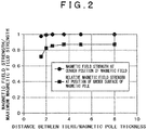
- FIG. 2 is a graph representing magnetic field strength as a function of a ratio of distance between tiers/magnetic pole thickness.
- the ratio of distance between tiers/magnetic pole thickness becomes less than 3
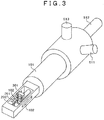
- Fig. 3 depicts the disposition of a sample holder frame 101, holder slots 102, the sample 201, a cantilevered beam shaped sample supporting element (holding element) 202, the magnetic field application element 301, and magnetic field application element moving mechanisms 511 to 513.
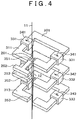
- the sample 201 is positioned in the center of the magnetic yoke gap 351 on the first tier at the most upstream position with respect to an electron beam flow 12, as depicted in Fig. 4 .
- the sample 201 fixed to the tip of the cantilevered beam shaped sample supporting element 202 is fixed to a frame element 101.
- the sample holder in which the sample 201 has been set is put into the electron beam apparatus 10 and irradiated with an electron beam. While viewing an electron microscopic image thus obtained, the positional relation between the sample 201 and the magnetic yoke gap 351 is adjusted by the moving mechanism 511 to 513. As depicted in Fig. 9 , when the sample holder is rotated by 90 degrees in the electron microscope, the electron beam 12 passes through the slots 102 made on both sides of the holder. Likewise, while viewing an electron microscopic image, the positional relation between the sample 201 and the magnetic yoke gap 351 can be adjusted by the moving mechanism 511 to 513.
- an information processing unit 601 that coordinately changes the conduction currents 341 to 343 for the coil windings on the respective tiers and the conduction currents for electron beam deflecting coils 15, 16 in the main body of the electron beam apparatus 10.
- the magnetic yokes 311 to 313 on the respective tiers are made of a material such as 80-20 permalloy or 50-50 permalloy which is a soft magnetic material with a property in which remnant magnetization is extremely small and saturated magnetization is large.
- each of the magnetic yokes 311 to 313 on the respective tiers is formed of a monolithic member. It is preferable that each yoke is a monolithic part except for its magnetic gap.
- a large magnetic field can be obtained by making the magnetic yokes 311 to 313 on the respective tiers have a narrow magnetic gap length 371 to 373 of 500 ⁇ m or less.
- high assembly precision is required in order to arrange the magnetic yoke gaps 351 to 353 having such a small length along the optical axis 11.
- Difficulty as mentioned above can be avoided by machining the magnetic yokes 311 to 313 as an integral structure member. To create narrow magnetic yoke gaps 315 to 353 along the optical axis 11, it is effective to perform wire cut machining using an extra fine wire or use an electric discharge machining device among others.
- the sample holder depicted in Fig. 3 is mounted in the charged particle beam apparatus depicted in Fig. 5 and a magnetic material sample is observed. Then, a good result has been obtained successfully.
- a sample holder and a charged particle beam apparatus using the same, capable of reducing or preventing the influence of a charged particle beam deflected by applying a magnetic field to a sample and provided with means for simply switching between a mode of observing a sample while applying a magnetic field to the sample, and a mode free of a magnetic field in which a magnetic field becomes zero completely.
- a sample by working a sample to be smaller than a magnetic yoke gap (e.g., 500 ⁇ m or less), it is possible to apply a large magnetic field to the sample without causing a large current to flow using a large exciting coil.
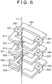
- FIG. 6 A second embodiment is described using Fig. 6 . Note that the matters described in the first embodiment section, but not described in this section, can also be applied to this embodiment unless there are special circumstances.
- a sample is positioned in the center of the magnetic yoke gap 352 on an intermediate tier which is the second one from the most upstream position with respect to the electron beam flow, as depicted in Fig. 6 .
- Rough adjustment in air and positioning in the electron microscope can be performed in the same way as described in the first embodiment section.
- An advantage of positioning the sample as above is that it is possible to apply, to the sample, a magnetic field that is twice as much as the magnetic field in the case of the first embodiment.
- a large displacement of the electron beam trajectory 12 from the sample 201 may take place and it is thus necessary to move the sample to trace the magnetic fields.
- FIG. 5 it is also effective to install an information processing unit 601 and a current control unit 602 that coordinately control the conduction currents 341 to 343 for the coil windings on the respective tiers, the conduction currents for electron beam deflecting coils 15 in the main body of the electron beam apparatus 10, and a sample moving mechanism 22 in the main body of the charged particle beam apparatus.
- a reference numeral 52 denotes a control signal line for the sample moving mechanism and a reference numeral 506 denotes an objective lens.
- the sample holder depicted in Fig. 6 is mounted in the charged particle beam apparatus depicted in Fig. 5 and a magnetic material sample is observed. Then, a good result has been obtained successfully.
- a sample holder and a charged particle beam apparatus using the same, capable of reducing or preventing the influence of a charged particle beam deflected by applying a magnetic field to a sample and provided with means for simply switching between a mode of observing a sample while applying a magnetic field to the sample, and a mode free of a magnetic field in which a magnetic field becomes zero completely.
- a sample on the intermediate tier, it is possible to augment the strength of the magnetic field applied.
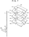
- FIG. 7 A third embodiment is described using Fig. 7 . Note that the matters described in the first or second embodiment section, but not described in this section, can also be applied to this embodiment unless there are special circumstances.
- the magnetic field in the position of a sample is put to zero by moving the magnetic field application element to a position quite far from the optical axis by the moving mechanism, as depicted in Fig. 7 .
- the magnetic fields in the gaps 361 to 363 have a finite value which is not zero, because of remnant magnetization of the magnetic yokes 311 to 313.
- An advantage of the present embodiment is that it is possible to place the sample in a condition that is completely free of a magnetic field.
- the sample holder depicted in Fig. 7 is mounted in the charged particle beam apparatus depicted in Fig. 5 and a magnetic material sample is observed. Then, a good result has been obtained successfully.
- a sample holder and a charged particle beam apparatus using the same, capable of reducing or preventing the influence of a charged particle beam deflected by applying a magnetic field to a sample and provided with means for simply switching between a mode of observing a sample while applying a magnetic field to the sample, and a mode free of a magnetic field in which a magnetic field becomes zero completely.
- a part of the configuration of an embodiment can be replaced by the configuration of another embodiment.
- the configuration of another embodiment can be added.
- another configuration can be added to it, it can be removed, or it can be replaced by another configuration.
Landscapes
- Chemical & Material Sciences (AREA)
- Analytical Chemistry (AREA)
- Analysing Materials By The Use Of Radiation (AREA)
Description
- The present invention relates to a sample holder and a charged particle beam apparatus using the same, suitable for applying a magnetic field to a sample to be observed or worked.
- When an electron beam passes through a magnetic material sample placed in an electron microscope, electrons are deflected by Lorentz force caused by magnetic fluxes inside the sample. By Lorentz electron microscopy and electron beam holography which apply this principle, it is possible to observe magnetic domain structures inside a sample. This method is most effective in investigating the magnetic response of an in-plane component of magnetization of a sample upon applying a magnetic field to the sample along an in-plane direction.
- By incorporating a magnetic field application element provided with a magnetic circuit including a magnetic core made of a soft magnetic material and a coil for magnetic field application into a sample holding device, an "in-situ" observation of a change in-plane magnetic domain structure of a sample is performed during application of a magnetic field perpendicular to an optical axis. Samples for electron microscopes generally have an external form like the shape of a disc with a diameter of 3 mm. While it is possible to accurately position a sample inside a magnetic gap that is larger than the sample diameter and apply a magnetic field along a direction parallel to the plane of the sample, a maximum magnetic field is not more than several tens of oersteds (1 Oe = 79,6 A/m) in most cases. Accordingly, in order to increase a magnetic field applied, it is practiced to bring the surface of a sample in contact with the top and under side surfaces of a pair of magnetic poles having a magnetic gap whose width is narrower than the size of a sample (Japanese Published Unexamined Patent Application Nos.
Hei 8-264146 2007-80724 - Even in a case where this method is used, a maximum applied magnetic field is not more than about 200 oersteds. This is because this mechanism makes it difficult to accurately position a sample to be aligned with the magnetic gap and, accordingly, the magnetic gap remains on the order of 1 mm.
- There is also an omni-directional type magnetic field application device including a set of superconductive electromagnets installed within a main body so as to surround a sample holding device (Japanese Published Unexamined Patent Application No.
2002-296333 - In the light of the background art discussed above, the present inventors have further examined matters that are likely to be a problem encountered in the working or observation of a magnetic material sample in future and thought that countermeasures are needed to address, particularly, among others, the following disadvantages: charged particles such as electrons are considerably deflected when a large magnetic field of several kilooersteds is applied to a sample; and it is impossible to switch between a state of application of a magnetic field to a sample and no magnetic field state.
- In view of the foregoing problems, an object of the present invention is to provide a sample holder and a charged particle beam apparatus using the same, capable of reducing or preventing the influence of a charged particle beam deflected by applying a magnetic field to a sample and provided with a means for simply switching between a mode of observing a sample while applying a magnetic field to the sample, and a mode free of a magnetic field, in which a magnetic field becomes zero completely.
- To achieve the foregoing object, one aspect of the present invention resides in a sample holder according to
claim 1. - It is possible to provide a sample holder and a charged particle beam apparatus using the same, capable of reducing or preventing the influence of a charged particle beam deflected by applying a magnetic field to a sample and provided with means for simply switching between a mode of observing a sample while applying a magnetic field to the sample, and a mode free of a magnetic field in which a magnetic field becomes zero completely.
-
-
Fig. 1 is a cross-sectional view of a principal section of a sample holder pertaining to a first embodiment of the present invention, which illustrates three-tier magnetic field application that deflects an electron beam and returns it back to its course, particularly depicting an electron beam trajectory and an angle of deflection; -
Fig. 2 is a graph representing magnetic field strength as a function of a ratio of distance between tiers/magnetic pole thickness; -
Fig. 3 is a schematic overall perspective view of the sample holder pertaining to the first embodiment of the present invention, which depicts a positional relation among a frame element, a sample, a magnetic field application element, and a moving mechanism; -
Fig. 4 is a perspective view of the principal section of the sample holder pertaining to the first embodiment of the present invention in a case where a sample is positioned inside a gap on a first tier; -
Fig. 5 is a schematic diagram of a mechanism that coordinately controls conduction currents for coils, deflecting coils in the main body of an electron beam apparatus, and a sample position in a charged particle beam apparatus pertaining to the first embodiment of the present invention; -
Fig. 6 is a perspective view of a principal section of a sample holder pertaining to a second embodiment of the present invention in a case where a sample is positioned inside a gap on a second tier and a maximum magnetic field is applied; -
Fig. 7 is a perspective view of the principal section of the sample holder pertaining to the second embodiment of the present invention in a case where a sample and the magnetic field application element are positioned away from each other; -
Fig. 8 is a perspective view of a basic structure of three-tier magnetic pole elements in the sample holder pertaining to the first embodiment of the present invention; and -
Fig. 9 is schematic overall perspective view depicting a positional relation among an electron beam, a sample, and magnetic pole elements when the sample holder depicted inFig. 3 is tiled by 90 degrees. - In order to provide means for simply switching between a mode of observing a sample positioned in the center of a magnetic gap while applying a large magnetic field of several kilooersteds, which is perpendicular to an optical axis of a charged particle beam apparatus, to the sample, and a mode free of a magnetic field in which a magnetic field becomes zero completely, a holder for magnetic field application is contrived, provided with a function of positioning a sample fixed to the tip of a cantilever-beam-shaped sample holding element in the center of one of magnetic gaps having a small gap width and a small thickness, formed in a magnetic field application element (magnetic yokes), using a moving mechanism. Also, the holder for magnetic field application is contrived in which it is possible to easily switch between the magnetic field application and observation mode and the mode free of a magnetic field by a movable and integral magnetic field application mechanism provided with a plurality of tiers of the magnetic yokes. In order to apply a large magnetic field of several kilooersteds to a sample, herein, the sample is worked to desired dimensions so as to fit in a magnetic yoke gap and used. This enables making exciting coils smaller and reducing a conduction current.
- By positioning a sample inside one of the magnetic gaps having a small thickness and a small gap width, it is possible to apply a large magnetic field to the sample along an in-plane direction and reduce the amount of deflection of an electron beam. The integral magnetic field application mechanism including multiple tiers of magnetic yokes is movable by the moving mechanism. This can change a relative positional relation between the magnetic field application element and the sample and enables the apparatus to function in a plurality of modes.
- In the following, the invention will be described by way of embodiments and using the drawings.
- A first embodiment of the present invention is described using
Figs. 1 through 5 ,8 , and9 .Fig. 8 depicts a perspective view of a basic structure of a magneticfield application element 301 having three-tiermagnetic gaps 351 to 353 in a sample holder pertaining to the first embodiment. A first tier of the magnetic field application element includes amagnetic yoke 311 with amagnetic gap 351 andwindings 331; a second tier thereof includes amagnetic yoke 312 with amagnetic gap 352 andwindings 332; and a third tier thereof includes amagnetic yoke 313 with amagnetic gap 353 andwindings 333, respectively. By allowingcurrents magnetic fields magnetic gaps field application element 301 has three tiers in the present embodiment, it may have more tiers. InFig. 8 , areference numeral 317 denotes thickness t of a magnetic pole element;reference numeral 371 denotes length L of a magnetic gap on the first tier; reference numeral 372 denotes length L of a magnetic gap on the second tier; andreference numeral 373 denotes length L of a magnetic gap on the third tier. Note that the same reference numerals denote the same components throughout all drawings. In the present embodiment, descriptions are provided for a case where electron beams are used, which are also applicable in a case where ion beams are used. -
Fig. 1 is a cross-sectional view of a principal section of the sample holder pertaining to the present embodiment, which illustrates three-tier magnetic field application that deflects an electron beam and returns it back to its course, particularly depicting an electron beam trajectory and an angle of deflection. Through the use ofFig. 1 , an explanation is provided about the electron beam trajectory when the electron beam passes through the three-tiermagnetic yoke gaps 351 to 353. By applying a magnetic field H in a forward direction to the first and third tiers and applying a magnetic field in a reverse direction, multiplied by two times the magnetic field H, to the intermediate tier, anelectron beam trajectory 12 is deflected, as it passes through the three tiers for deflection, and returns to anoptical axis 11 of an electron beam apparatus when exiting the three tiers. Themagnetic fields 361 to 363 that are generated by themagnetic yoke gaps 351 to 353 are proportional to a conduction current I and the number of coil windings N and inversely proportional to thelengths 371 to 373 (L) of the magnetic gaps, as expressed in Equation (1). By forming the magnetic gaps having extremelynarrow lengths 371 to 373 and positioning a sample in the center of one of the gaps, it is possible to apply a large magnetic field on the order of kilooersteds to the sample. An advantage of this arrangement is that, when the strength of themagnetic field 361 has been changed, theelectron beam trajectory 12 is displaced from asample 201 to only a small degree. This small displacement can easily be corrected by coils for modifying the direction of the electron beam in the main body of the electron beam apparatus. The deflection of the electron beam takes place only inside the magnetic gaps and the beam follows a straight line trajectory between each tier. Equation (2) expresses that the angle of deflection θ is proportional to the product of magnetic field strength H and the length of an electron range within the magnetic field. The angle of deflection θ inside a gap is proportional to the thickness 317 (t) of a magnetic pole element, as expressed in Equation (2). Thus, an increase in the angle of deflection θ can be suppressed by reducing the thickness of a magnetic pole element, even if the strength of themagnetic fields 361 to 363 is large.
[Equation 1]

- The displacement (distance) Δx of the electron beam trajectory when the electron beam has come at the second-tier
magnetic yoke gap 352 takes place when electrons are traveling deflected by the angle of deflection θ in space that is free of a magnetic field between magnetic pole elements; the displacement (distance) Δx can be represented approximately in Equation (3), where a distance between tiers is denoted by D. Equation (3) expresses that the displacement distance Δx of the electron beam trajectory from the optical axis is proportional to the product of the angle of deflection θ and the distance between tiers D.
[Equation 3]
- Therefore, in a case where magnetic field space is designed to be small as in the present embodiment, there is a possibility that the electron beam trajectory deviates from the magnetic field space, and it is thus important to decrease the distance between tiers 316 (D) so that the displacement of the electron beam from the optical axis can be suppressed to be small. On the other hand, if the distance between
tiers 316 is made too small, there is a possibility that that the maximum strength of a magnetic field produced in a magnetic gap is reduced by the influence of a reverse magnetic field produced on an adjacent tier or the uniformity of the magnetic fields in themagnetic yoke gaps 351 to 315 is lost.Fig. 2 is a graph representing magnetic field strength as a function of a ratio of distance between tiers/magnetic pole thickness. As can be seen from the graph, when the ratio of distance between tiers/magnetic pole thickness becomes less than 3, there is a significant decrease in the magnetic field strength at a point where the optical axis intersects the position of the top surface (under surface) of a magnetic pole. This means that it becomes hard to position a sample inside a gap where a magnetic field gradient is small, though doing so is beneficial. Hence, it is preferable to make a configuration such that the ratio of distance between tiers/magnetic pole thickness will be not less than 3. -
Fig. 3 depicts the disposition of asample holder frame 101,holder slots 102, thesample 201, a cantilevered beam shaped sample supporting element (holding element) 202, the magneticfield application element 301, and magnetic field applicationelement moving mechanisms 511 to 513. In the present embodiment, thesample 201 is positioned in the center of themagnetic yoke gap 351 on the first tier at the most upstream position with respect to anelectron beam flow 12, as depicted inFig. 4 . Thesample 201 fixed to the tip of the cantilevered beam shapedsample supporting element 202 is fixed to aframe element 101. The magnetic field generating element (magnetic field application element) 301 including themagnetic yokes 311 to 313 withexciting coils 331 to 333 wound thereon, respectively having the magnetic gaps, is moved by the movingmechanism 511 to 513 so as to approach the sample and setting is performed so that thesample 201 to be observed is positioned in the center of themagnetic yoke gap 351 on the first tier. While it is convenient to make a rough adjustment under a stereoscopic microscope outside an electron microscope, theslots 102 made in theframe element 101 can make it easy to see a three-dimensional positional relation between thesample 201 and themagnetic yoke gap 351 on the first tier. - The sample holder in which the
sample 201 has been set is put into theelectron beam apparatus 10 and irradiated with an electron beam. While viewing an electron microscopic image thus obtained, the positional relation between thesample 201 and themagnetic yoke gap 351 is adjusted by the movingmechanism 511 to 513. As depicted inFig. 9 , when the sample holder is rotated by 90 degrees in the electron microscope, theelectron beam 12 passes through theslots 102 made on both sides of the holder. Likewise, while viewing an electron microscopic image, the positional relation between thesample 201 and themagnetic yoke gap 351 can be adjusted by the movingmechanism 511 to 513. - As depicted in
Fig. 5 , it is also effective to install aninformation processing unit 601 that coordinately changes theconduction currents 341 to 343 for the coil windings on the respective tiers and the conduction currents for electron beam deflecting coils 15, 16 in the main body of theelectron beam apparatus 10. - It is preferable that the
magnetic yokes 311 to 313 on the respective tiers are made of a material such as 80-20 permalloy or 50-50 permalloy which is a soft magnetic material with a property in which remnant magnetization is extremely small and saturated magnetization is large. - If the
magnetic yokes 311 to 313 on the respective tiers are each formed of a plurality of members, an assembly clearance that is made, accompanied by jointing the members, also functions as a magnetic gap, which thus results in a decrease in the strength of the magnetic fields produced in themagnetic gaps 361 to 363 arranged along the optical axis. Therefore, it is preferable that each of themagnetic yokes 311 to 313 on the respective tiers is formed of a monolithic member. It is preferable that each yoke is a monolithic part except for its magnetic gap. - A large magnetic field can be obtained by making the
magnetic yokes 311 to 313 on the respective tiers have a narrowmagnetic gap length 371 to 373 of 500 µm or less. However, high assembly precision is required in order to arrange themagnetic yoke gaps 351 to 353 having such a small length along theoptical axis 11. - Difficulty as mentioned above can be avoided by machining the
magnetic yokes 311 to 313 as an integral structure member. To create narrow magnetic yoke gaps 315 to 353 along theoptical axis 11, it is effective to perform wire cut machining using an extra fine wire or use an electric discharge machining device among others. - The sample holder depicted in
Fig. 3 is mounted in the charged particle beam apparatus depicted inFig. 5 and a magnetic material sample is observed. Then, a good result has been obtained successfully. - According to the present embodiment as described above, it is possible to provide a sample holder and a charged particle beam apparatus using the same, capable of reducing or preventing the influence of a charged particle beam deflected by applying a magnetic field to a sample and provided with means for simply switching between a mode of observing a sample while applying a magnetic field to the sample, and a mode free of a magnetic field in which a magnetic field becomes zero completely. In addition, by working a sample to be smaller than a magnetic yoke gap (e.g., 500 µm or less), it is possible to apply a large magnetic field to the sample without causing a large current to flow using a large exciting coil.
- A second embodiment is described using
Fig. 6 . Note that the matters described in the first embodiment section, but not described in this section, can also be applied to this embodiment unless there are special circumstances. - In the present embodiment, a sample is positioned in the center of the
magnetic yoke gap 352 on an intermediate tier which is the second one from the most upstream position with respect to the electron beam flow, as depicted inFig. 6 . Rough adjustment in air and positioning in the electron microscope can be performed in the same way as described in the first embodiment section. - An advantage of positioning the sample as above is that it is possible to apply, to the sample, a magnetic field that is twice as much as the magnetic field in the case of the first embodiment. However, when the strength of the
magnetic fields 361 to 363 has been changed, a large displacement of theelectron beam trajectory 12 from thesample 201 may take place and it is thus necessary to move the sample to trace the magnetic fields. - Alternatively, as depicted in
Fig. 5 , it is also effective to install aninformation processing unit 601 and acurrent control unit 602 that coordinately control theconduction currents 341 to 343 for the coil windings on the respective tiers, the conduction currents for electron beam deflecting coils 15 in the main body of theelectron beam apparatus 10, and asample moving mechanism 22 in the main body of the charged particle beam apparatus. Areference numeral 52 denotes a control signal line for the sample moving mechanism and areference numeral 506 denotes an objective lens. - The sample holder depicted in
Fig. 6 is mounted in the charged particle beam apparatus depicted inFig. 5 and a magnetic material sample is observed. Then, a good result has been obtained successfully. - According to the present embodiment as described above, it is possible to provide a sample holder and a charged particle beam apparatus using the same, capable of reducing or preventing the influence of a charged particle beam deflected by applying a magnetic field to a sample and provided with means for simply switching between a mode of observing a sample while applying a magnetic field to the sample, and a mode free of a magnetic field in which a magnetic field becomes zero completely. In addition, by positioning a sample on the intermediate tier, it is possible to augment the strength of the magnetic field applied.
- A third embodiment is described using
Fig. 7 . Note that the matters described in the first or second embodiment section, but not described in this section, can also be applied to this embodiment unless there are special circumstances. - In the present embodiment, the magnetic field in the position of a sample is put to zero by moving the magnetic field application element to a position quite far from the optical axis by the moving mechanism, as depicted in
Fig. 7 . Even if theconduction currents 341 to 343 are put to zero, the magnetic fields in thegaps 361 to 363 have a finite value which is not zero, because of remnant magnetization of themagnetic yokes 311 to 313. Hence, to realize a zero magnetic state of a sample, it is effective to move the magneticfield application element 301 physically away from the sample by the magnetic field applicationelement moving mechanism 513. An advantage of the present embodiment is that it is possible to place the sample in a condition that is completely free of a magnetic field. - The sample holder depicted in
Fig. 7 is mounted in the charged particle beam apparatus depicted inFig. 5 and a magnetic material sample is observed. Then, a good result has been obtained successfully. - According to the present embodiment as described above, it is possible to provide a sample holder and a charged particle beam apparatus using the same, capable of reducing or preventing the influence of a charged particle beam deflected by applying a magnetic field to a sample and provided with means for simply switching between a mode of observing a sample while applying a magnetic field to the sample, and a mode free of a magnetic field in which a magnetic field becomes zero completely.
- The present invention is not limited to the foregoing embodiments and various modifications are included therein. For example, the foregoing embodiments are those described in detail to explain the present invention clearly and the invention is not necessarily limited to those including all components described. A part of the configuration of an embodiment can be replaced by the configuration of another embodiment. To the configuration of an embodiment, the configuration of another embodiment can be added. As for a part of the configuration of each embodiment, another configuration can be added to it, it can be removed, or it can be replaced by another configuration.
Claims (7)
- A sample holder for a charged particle apparatus, the sample holder comprising:a magnetic field generating element (301) including three or more magnetic circuits, each having a magnetic gap (351-353) for applying a magnetic field to a sample (201), the magnetic circuits arranged in tiers, so that each magnetic gap is arranged to be placeable perpendicular to the optical axis of the charged particle beam apparatus, and a frame element (101) that defines an outside structure of the sample holder;characterized in a cantilever-beam-shaped sample holding element (202) that is adapted to hold the sample (201) on one end thereof; and a moving mechanism (511-513) that is adapted to adjust the relative position between the sample (201) and one of the magnetic gaps within the range of the magnetic gap.
- A charged particle beam apparatus using the sample holder according to claim 1,
wherein the magnetic circuits are formed in an integral structure in which the magnetic circuits are spaced from each other by a distance between said tiers that is three times or more as much as a thickness of a magnetic pole element. - A charged particle beam apparatus using the sample holder according to claim 1,
wherein the moving mechanism is adapted to move the sample (201) to a position inside any one of the magnetic gaps which are three or more in number and the charged particle beam apparatus comprises an information processing unit that changes an observation mode based on the position. - The charged particle beam apparatus according to claim 3,
wherein the information processing unit causes the moving mechanism to move the sample (201) outward from the magnetic gaps and changes the observation mode based on a fact that the sample (201) is positioned outside the magnetic gaps. - A charged particle beam apparatus using the sample holder according to claim 1,
wherein two or more ones of the three or more magnetic circuits are magnetic circuits for deflecting the charged particle beam and returning it back to its course. - A charged particle beam apparatus using the sample holder according to claim 1,
wherein the sample holding element (202) is fixed to the frame element (101). - The charged particle beam apparatus according to claim 6,
wherein the frame element (101) has slots for observing a sample (201) held by the sample holding element and a magnetic gap.
Applications Claiming Priority (1)
| Application Number | Priority Date | Filing Date | Title |
|---|---|---|---|
| JP2013092436A JP6061771B2 (en) | 2013-04-25 | 2013-04-25 | Sample holder and charged particle beam apparatus using the same |
Publications (3)
| Publication Number | Publication Date |
|---|---|
| EP2797099A2 EP2797099A2 (en) | 2014-10-29 |
| EP2797099A3 EP2797099A3 (en) | 2016-01-06 |
| EP2797099B1 true EP2797099B1 (en) | 2017-09-27 |
Family
ID=50513179
Family Applications (1)
| Application Number | Title | Priority Date | Filing Date |
|---|---|---|---|
| EP14165693.4A Not-in-force EP2797099B1 (en) | 2013-04-25 | 2014-04-23 | Magnetic field applying sample holder; and charged particle beam apparatus using same |
Country Status (3)
| Country | Link |
|---|---|
| US (1) | US9070532B2 (en) |
| EP (1) | EP2797099B1 (en) |
| JP (1) | JP6061771B2 (en) |
Cited By (1)
| Publication number | Priority date | Publication date | Assignee | Title |
|---|---|---|---|---|
| EP4145487A4 (en) * | 2020-05-27 | 2023-10-11 | Ningbo Institute of Materials Technology & Engineering, Chinese Academy of Sciences | Magnetic field generation device, and transmission electron microscope sample holder capable of applying magnetic field |
Families Citing this family (4)
| Publication number | Priority date | Publication date | Assignee | Title |
|---|---|---|---|---|
| JP6554066B2 (en) | 2016-05-31 | 2019-07-31 | 株式会社日立製作所 | Electron microscope for magnetic field measurement and magnetic field measurement method |
| JP6355703B2 (en) * | 2016-11-29 | 2018-07-11 | 株式会社メルビル | Sample holder |
| WO2018139220A1 (en) | 2017-01-24 | 2018-08-02 | 国立大学法人東北大学 | Method for creating electron-beam hologram, magnetic field information measurement method, and magnetic field information measuring device |
| WO2023020700A1 (en) * | 2021-08-20 | 2023-02-23 | Forschungszentrum Jülich GmbH | Magnetization device for an electron microscope and method |
Family Cites Families (10)
| Publication number | Priority date | Publication date | Assignee | Title |
|---|---|---|---|---|
| JPS58169762A (en) * | 1982-03-30 | 1983-10-06 | Internatl Precision Inc | Electron beam device |
| JPH08264146A (en) | 1995-03-24 | 1996-10-11 | Hitachi Ltd | Transmission electron microscope |
| US6476913B1 (en) * | 1998-11-30 | 2002-11-05 | Hitachi, Ltd. | Inspection method, apparatus and system for circuit pattern |
| DE19945344A1 (en) * | 1999-09-22 | 2001-03-29 | Leo Elektronenmikroskopie Gmbh | Particle-optical lighting and imaging system with a condenser-objective single-field lens |
| JP3469213B2 (en) | 2001-03-29 | 2003-11-25 | 株式会社日立製作所 | Magnetic field applied sample observation system |
| JP2005294181A (en) * | 2004-04-05 | 2005-10-20 | Jeol Ltd | Bulk sample holder |
| JP4759733B2 (en) | 2005-09-15 | 2011-08-31 | 国立大学法人東北大学 | electronic microscope |
| JP2011003533A (en) * | 2009-05-20 | 2011-01-06 | Jeol Ltd | Magnetic domain imaging system |
| JP5645386B2 (en) | 2009-09-30 | 2014-12-24 | 株式会社日立製作所 | Electromagnetic field application device |
| JP2012129137A (en) * | 2010-12-17 | 2012-07-05 | Hitachi Ltd | Field application sample holding device and charged particle beam device using the same |
-
2013
- 2013-04-25 JP JP2013092436A patent/JP6061771B2/en not_active Expired - Fee Related
-
2014
- 2014-04-23 EP EP14165693.4A patent/EP2797099B1/en not_active Not-in-force
- 2014-04-24 US US14/260,452 patent/US9070532B2/en not_active Expired - Fee Related
Cited By (1)
| Publication number | Priority date | Publication date | Assignee | Title |
|---|---|---|---|---|
| EP4145487A4 (en) * | 2020-05-27 | 2023-10-11 | Ningbo Institute of Materials Technology & Engineering, Chinese Academy of Sciences | Magnetic field generation device, and transmission electron microscope sample holder capable of applying magnetic field |
Also Published As
| Publication number | Publication date |
|---|---|
| EP2797099A2 (en) | 2014-10-29 |
| EP2797099A3 (en) | 2016-01-06 |
| US20140319371A1 (en) | 2014-10-30 |
| US9070532B2 (en) | 2015-06-30 |
| JP6061771B2 (en) | 2017-01-18 |
| JP2014216180A (en) | 2014-11-17 |
Similar Documents
| Publication | Publication Date | Title |
|---|---|---|
| EP2797099B1 (en) | Magnetic field applying sample holder; and charged particle beam apparatus using same | |
| JP6173862B2 (en) | electronic microscope | |
| EP2091063B1 (en) | Electron beam observation device using a pre-specimen magnetic field as image-forming lens and specimen observation method | |
| EP1376649B1 (en) | Magnetic field applying sample observing system | |
| JP5156429B2 (en) | Electron beam equipment | |
| EP3396696A1 (en) | Compact deflecting magnet | |
| JP5648919B2 (en) | Ion implanter | |
| JP2017511600A (en) | Superconducting magnetic field stabilizer | |
| JP2023527008A (en) | Magnetic field generator and transmission electron microscope sample holder for applying magnetic field | |
| EP3113206B1 (en) | X-ray generator and adjustment method therefor | |
| JP2007280966A (en) | Electrooptic lens system | |
| EP4318546A2 (en) | Electron diffraction holography | |
| US8773227B2 (en) | Method for fabricating an electromagnetic actuator, an electromagnetic actuator, and a charged particle device comprising the same | |
| EP2525384A2 (en) | Method and structure for controlling magnetic field distributions in an ExB wien filter | |
| JP5140103B2 (en) | Linear motor pair, moving stage, and electron microscope | |
| JP2012199022A (en) | Electron microscope, and diffraction image observation method | |
| JP5512797B2 (en) | Electron beam interference device | |
| US20110073759A1 (en) | Electromagentic field application system | |
| JP2011003533A (en) | Magnetic domain imaging system | |
| Steierl et al. | Surface domain imaging in external magnetic fields | |
| JP2012129137A (en) | Field application sample holding device and charged particle beam device using the same | |
| EP4020519A1 (en) | Magnetic field free sample plane for charged particle microscope | |
| JP2005116365A (en) | Transmission electron microscope equipped with phase plate and lens system for phase plate | |
| WO2015094382A1 (en) | C-shaped yoke coil mass analyzer apparatus for separating desired ion species from unwanted ion species in ribbon ion beams of arbitrary breadth | |
| Egerton et al. | Electron Optics |
Legal Events
| Date | Code | Title | Description |
|---|---|---|---|
| PUAI | Public reference made under article 153(3) epc to a published international application that has entered the european phase |
Free format text: ORIGINAL CODE: 0009012 |
|
| 17P | Request for examination filed |
Effective date: 20140509 |
|
| AK | Designated contracting states |
Kind code of ref document: A2 Designated state(s): AL AT BE BG CH CY CZ DE DK EE ES FI FR GB GR HR HU IE IS IT LI LT LU LV MC MK MT NL NO PL PT RO RS SE SI SK SM TR |
|
| AX | Request for extension of the european patent |
Extension state: BA ME |
|
| PUAL | Search report despatched |
Free format text: ORIGINAL CODE: 0009013 |
|
| AK | Designated contracting states |
Kind code of ref document: A3 Designated state(s): AL AT BE BG CH CY CZ DE DK EE ES FI FR GB GR HR HU IE IS IT LI LT LU LV MC MK MT NL NO PL PT RO RS SE SI SK SM TR |
|
| AX | Request for extension of the european patent |
Extension state: BA ME |
|
| RIC1 | Information provided on ipc code assigned before grant |
Ipc: H01J 37/20 20060101ALI20151202BHEP Ipc: H01J 37/09 20060101AFI20151202BHEP |
|
| GRAP | Despatch of communication of intention to grant a patent |
Free format text: ORIGINAL CODE: EPIDOSNIGR1 |
|
| INTG | Intention to grant announced |
Effective date: 20170426 |
|
| GRAS | Grant fee paid |
Free format text: ORIGINAL CODE: EPIDOSNIGR3 |
|
| GRAA | (expected) grant |
Free format text: ORIGINAL CODE: 0009210 |
|
| AK | Designated contracting states |
Kind code of ref document: B1 Designated state(s): AL AT BE BG CH CY CZ DE DK EE ES FI FR GB GR HR HU IE IS IT LI LT LU LV MC MK MT NL NO PL PT RO RS SE SI SK SM TR |
|
| REG | Reference to a national code |
Ref country code: GB Ref legal event code: FG4D |
|
| REG | Reference to a national code |
Ref country code: CH Ref legal event code: EP |
|
| REG | Reference to a national code |
Ref country code: AT Ref legal event code: REF Ref document number: 932723 Country of ref document: AT Kind code of ref document: T Effective date: 20171015 |
|
| REG | Reference to a national code |
Ref country code: IE Ref legal event code: FG4D |
|
| REG | Reference to a national code |
Ref country code: DE Ref legal event code: R096 Ref document number: 602014014971 Country of ref document: DE |
|
| PG25 | Lapsed in a contracting state [announced via postgrant information from national office to epo] |
Ref country code: FI Free format text: LAPSE BECAUSE OF FAILURE TO SUBMIT A TRANSLATION OF THE DESCRIPTION OR TO PAY THE FEE WITHIN THE PRESCRIBED TIME-LIMIT Effective date: 20170927 Ref country code: SE Free format text: LAPSE BECAUSE OF FAILURE TO SUBMIT A TRANSLATION OF THE DESCRIPTION OR TO PAY THE FEE WITHIN THE PRESCRIBED TIME-LIMIT Effective date: 20170927 Ref country code: NO Free format text: LAPSE BECAUSE OF FAILURE TO SUBMIT A TRANSLATION OF THE DESCRIPTION OR TO PAY THE FEE WITHIN THE PRESCRIBED TIME-LIMIT Effective date: 20171227 Ref country code: HR Free format text: LAPSE BECAUSE OF FAILURE TO SUBMIT A TRANSLATION OF THE DESCRIPTION OR TO PAY THE FEE WITHIN THE PRESCRIBED TIME-LIMIT Effective date: 20170927 Ref country code: LT Free format text: LAPSE BECAUSE OF FAILURE TO SUBMIT A TRANSLATION OF THE DESCRIPTION OR TO PAY THE FEE WITHIN THE PRESCRIBED TIME-LIMIT Effective date: 20170927 |
|
| REG | Reference to a national code |
Ref country code: NL Ref legal event code: MP Effective date: 20170927 |
|
| REG | Reference to a national code |
Ref country code: LT Ref legal event code: MG4D |
|
| REG | Reference to a national code |
Ref country code: AT Ref legal event code: MK05 Ref document number: 932723 Country of ref document: AT Kind code of ref document: T Effective date: 20170927 |
|
| PG25 | Lapsed in a contracting state [announced via postgrant information from national office to epo] |
Ref country code: GR Free format text: LAPSE BECAUSE OF FAILURE TO SUBMIT A TRANSLATION OF THE DESCRIPTION OR TO PAY THE FEE WITHIN THE PRESCRIBED TIME-LIMIT Effective date: 20171228 Ref country code: LV Free format text: LAPSE BECAUSE OF FAILURE TO SUBMIT A TRANSLATION OF THE DESCRIPTION OR TO PAY THE FEE WITHIN THE PRESCRIBED TIME-LIMIT Effective date: 20170927 Ref country code: BG Free format text: LAPSE BECAUSE OF FAILURE TO SUBMIT A TRANSLATION OF THE DESCRIPTION OR TO PAY THE FEE WITHIN THE PRESCRIBED TIME-LIMIT Effective date: 20171227 Ref country code: RS Free format text: LAPSE BECAUSE OF FAILURE TO SUBMIT A TRANSLATION OF THE DESCRIPTION OR TO PAY THE FEE WITHIN THE PRESCRIBED TIME-LIMIT Effective date: 20170927 |
|
| PG25 | Lapsed in a contracting state [announced via postgrant information from national office to epo] |
Ref country code: NL Free format text: LAPSE BECAUSE OF FAILURE TO SUBMIT A TRANSLATION OF THE DESCRIPTION OR TO PAY THE FEE WITHIN THE PRESCRIBED TIME-LIMIT Effective date: 20170927 |
|
| PG25 | Lapsed in a contracting state [announced via postgrant information from national office to epo] |
Ref country code: RO Free format text: LAPSE BECAUSE OF FAILURE TO SUBMIT A TRANSLATION OF THE DESCRIPTION OR TO PAY THE FEE WITHIN THE PRESCRIBED TIME-LIMIT Effective date: 20170927 Ref country code: CZ Free format text: LAPSE BECAUSE OF FAILURE TO SUBMIT A TRANSLATION OF THE DESCRIPTION OR TO PAY THE FEE WITHIN THE PRESCRIBED TIME-LIMIT Effective date: 20170927 Ref country code: ES Free format text: LAPSE BECAUSE OF FAILURE TO SUBMIT A TRANSLATION OF THE DESCRIPTION OR TO PAY THE FEE WITHIN THE PRESCRIBED TIME-LIMIT Effective date: 20170927 |
|
| PG25 | Lapsed in a contracting state [announced via postgrant information from national office to epo] |
Ref country code: SM Free format text: LAPSE BECAUSE OF FAILURE TO SUBMIT A TRANSLATION OF THE DESCRIPTION OR TO PAY THE FEE WITHIN THE PRESCRIBED TIME-LIMIT Effective date: 20170927 Ref country code: SK Free format text: LAPSE BECAUSE OF FAILURE TO SUBMIT A TRANSLATION OF THE DESCRIPTION OR TO PAY THE FEE WITHIN THE PRESCRIBED TIME-LIMIT Effective date: 20170927 Ref country code: IT Free format text: LAPSE BECAUSE OF FAILURE TO SUBMIT A TRANSLATION OF THE DESCRIPTION OR TO PAY THE FEE WITHIN THE PRESCRIBED TIME-LIMIT Effective date: 20170927 Ref country code: EE Free format text: LAPSE BECAUSE OF FAILURE TO SUBMIT A TRANSLATION OF THE DESCRIPTION OR TO PAY THE FEE WITHIN THE PRESCRIBED TIME-LIMIT Effective date: 20170927 Ref country code: AT Free format text: LAPSE BECAUSE OF FAILURE TO SUBMIT A TRANSLATION OF THE DESCRIPTION OR TO PAY THE FEE WITHIN THE PRESCRIBED TIME-LIMIT Effective date: 20170927 Ref country code: IS Free format text: LAPSE BECAUSE OF FAILURE TO SUBMIT A TRANSLATION OF THE DESCRIPTION OR TO PAY THE FEE WITHIN THE PRESCRIBED TIME-LIMIT Effective date: 20180127 |
|
| REG | Reference to a national code |
Ref country code: DE Ref legal event code: R097 Ref document number: 602014014971 Country of ref document: DE |
|
| PG25 | Lapsed in a contracting state [announced via postgrant information from national office to epo] |
Ref country code: DK Free format text: LAPSE BECAUSE OF FAILURE TO SUBMIT A TRANSLATION OF THE DESCRIPTION OR TO PAY THE FEE WITHIN THE PRESCRIBED TIME-LIMIT Effective date: 20170927 |
|
| PGFP | Annual fee paid to national office [announced via postgrant information from national office to epo] |
Ref country code: DE Payment date: 20180426 Year of fee payment: 5 |
|
| PLBE | No opposition filed within time limit |
Free format text: ORIGINAL CODE: 0009261 |
|
| STAA | Information on the status of an ep patent application or granted ep patent |
Free format text: STATUS: NO OPPOSITION FILED WITHIN TIME LIMIT |
|
| PG25 | Lapsed in a contracting state [announced via postgrant information from national office to epo] |
Ref country code: PL Free format text: LAPSE BECAUSE OF FAILURE TO SUBMIT A TRANSLATION OF THE DESCRIPTION OR TO PAY THE FEE WITHIN THE PRESCRIBED TIME-LIMIT Effective date: 20170927 |
|
| 26N | No opposition filed |
Effective date: 20180628 |
|
| PGFP | Annual fee paid to national office [announced via postgrant information from national office to epo] |
Ref country code: GB Payment date: 20180423 Year of fee payment: 5 |
|
| PG25 | Lapsed in a contracting state [announced via postgrant information from national office to epo] |
Ref country code: MC Free format text: LAPSE BECAUSE OF FAILURE TO SUBMIT A TRANSLATION OF THE DESCRIPTION OR TO PAY THE FEE WITHIN THE PRESCRIBED TIME-LIMIT Effective date: 20170927 Ref country code: SI Free format text: LAPSE BECAUSE OF FAILURE TO SUBMIT A TRANSLATION OF THE DESCRIPTION OR TO PAY THE FEE WITHIN THE PRESCRIBED TIME-LIMIT Effective date: 20170927 |
|
| REG | Reference to a national code |
Ref country code: CH Ref legal event code: PL |
|
| REG | Reference to a national code |
Ref country code: BE Ref legal event code: MM Effective date: 20180430 |
|
| REG | Reference to a national code |
Ref country code: IE Ref legal event code: MM4A |
|
| PG25 | Lapsed in a contracting state [announced via postgrant information from national office to epo] |
Ref country code: LU Free format text: LAPSE BECAUSE OF NON-PAYMENT OF DUE FEES Effective date: 20180423 |
|
| PG25 | Lapsed in a contracting state [announced via postgrant information from national office to epo] |
Ref country code: BE Free format text: LAPSE BECAUSE OF NON-PAYMENT OF DUE FEES Effective date: 20180430 Ref country code: LI Free format text: LAPSE BECAUSE OF NON-PAYMENT OF DUE FEES Effective date: 20180430 Ref country code: CH Free format text: LAPSE BECAUSE OF NON-PAYMENT OF DUE FEES Effective date: 20180430 |
|
| PG25 | Lapsed in a contracting state [announced via postgrant information from national office to epo] |
Ref country code: IE Free format text: LAPSE BECAUSE OF NON-PAYMENT OF DUE FEES Effective date: 20180423 Ref country code: FR Free format text: LAPSE BECAUSE OF NON-PAYMENT OF DUE FEES Effective date: 20180430 |
|
| REG | Reference to a national code |
Ref country code: DE Ref legal event code: R119 Ref document number: 602014014971 Country of ref document: DE |
|
| GBPC | Gb: european patent ceased through non-payment of renewal fee |
Effective date: 20190423 |
|
| PG25 | Lapsed in a contracting state [announced via postgrant information from national office to epo] |
Ref country code: MT Free format text: LAPSE BECAUSE OF NON-PAYMENT OF DUE FEES Effective date: 20180423 Ref country code: GB Free format text: LAPSE BECAUSE OF NON-PAYMENT OF DUE FEES Effective date: 20190423 Ref country code: DE Free format text: LAPSE BECAUSE OF NON-PAYMENT OF DUE FEES Effective date: 20191101 |
|
| PG25 | Lapsed in a contracting state [announced via postgrant information from national office to epo] |
Ref country code: TR Free format text: LAPSE BECAUSE OF FAILURE TO SUBMIT A TRANSLATION OF THE DESCRIPTION OR TO PAY THE FEE WITHIN THE PRESCRIBED TIME-LIMIT Effective date: 20170927 |
|
| PG25 | Lapsed in a contracting state [announced via postgrant information from national office to epo] |
Ref country code: HU Free format text: LAPSE BECAUSE OF FAILURE TO SUBMIT A TRANSLATION OF THE DESCRIPTION OR TO PAY THE FEE WITHIN THE PRESCRIBED TIME-LIMIT; INVALID AB INITIO Effective date: 20140423 Ref country code: PT Free format text: LAPSE BECAUSE OF FAILURE TO SUBMIT A TRANSLATION OF THE DESCRIPTION OR TO PAY THE FEE WITHIN THE PRESCRIBED TIME-LIMIT Effective date: 20170927 |
|
| PG25 | Lapsed in a contracting state [announced via postgrant information from national office to epo] |
Ref country code: MK Free format text: LAPSE BECAUSE OF NON-PAYMENT OF DUE FEES Effective date: 20170927 Ref country code: CY Free format text: LAPSE BECAUSE OF FAILURE TO SUBMIT A TRANSLATION OF THE DESCRIPTION OR TO PAY THE FEE WITHIN THE PRESCRIBED TIME-LIMIT Effective date: 20170927 |
|
| PG25 | Lapsed in a contracting state [announced via postgrant information from national office to epo] |
Ref country code: AL Free format text: LAPSE BECAUSE OF FAILURE TO SUBMIT A TRANSLATION OF THE DESCRIPTION OR TO PAY THE FEE WITHIN THE PRESCRIBED TIME-LIMIT Effective date: 20170927 |