EP2797037B1 - Electronic mold counter device - Google Patents
Electronic mold counter device Download PDFInfo
- Publication number
- EP2797037B1 EP2797037B1 EP12860304.0A EP12860304A EP2797037B1 EP 2797037 B1 EP2797037 B1 EP 2797037B1 EP 12860304 A EP12860304 A EP 12860304A EP 2797037 B1 EP2797037 B1 EP 2797037B1
- Authority
- EP
- European Patent Office
- Prior art keywords
- mold
- unit
- press
- case
- fittings
- Prior art date
- Legal status (The legal status is an assumption and is not a legal conclusion. Google has not performed a legal analysis and makes no representation as to the accuracy of the status listed.)
- Not-in-force
Links
Images


Classifications
-
- G—PHYSICS
- G06—COMPUTING OR CALCULATING; COUNTING
- G06M—COUNTING MECHANISMS; COUNTING OF OBJECTS NOT OTHERWISE PROVIDED FOR
- G06M1/00—Design features of general application
- G06M1/08—Design features of general application for actuating the drive
- G06M1/10—Design features of general application for actuating the drive by electric or magnetic means
- G06M1/101—Design features of general application for actuating the drive by electric or magnetic means by electro-optical means
-
- G—PHYSICS
- G06—COMPUTING OR CALCULATING; COUNTING
- G06M—COUNTING MECHANISMS; COUNTING OF OBJECTS NOT OTHERWISE PROVIDED FOR
- G06M1/00—Design features of general application
- G06M1/08—Design features of general application for actuating the drive
- G06M1/10—Design features of general application for actuating the drive by electric or magnetic means
-
- B—PERFORMING OPERATIONS; TRANSPORTING
- B29—WORKING OF PLASTICS; WORKING OF SUBSTANCES IN A PLASTIC STATE IN GENERAL
- B29C—SHAPING OR JOINING OF PLASTICS; SHAPING OF MATERIAL IN A PLASTIC STATE, NOT OTHERWISE PROVIDED FOR; AFTER-TREATMENT OF THE SHAPED PRODUCTS, e.g. REPAIRING
- B29C45/00—Injection moulding, i.e. forcing the required volume of moulding material through a nozzle into a closed mould; Apparatus therefor
- B29C45/17—Component parts, details or accessories; Auxiliary operations
-
- B—PERFORMING OPERATIONS; TRANSPORTING
- B29—WORKING OF PLASTICS; WORKING OF SUBSTANCES IN A PLASTIC STATE IN GENERAL
- B29C—SHAPING OR JOINING OF PLASTICS; SHAPING OF MATERIAL IN A PLASTIC STATE, NOT OTHERWISE PROVIDED FOR; AFTER-TREATMENT OF THE SHAPED PRODUCTS, e.g. REPAIRING
- B29C45/00—Injection moulding, i.e. forcing the required volume of moulding material through a nozzle into a closed mould; Apparatus therefor
- B29C45/17—Component parts, details or accessories; Auxiliary operations
- B29C2045/1784—Component parts, details or accessories not otherwise provided for; Auxiliary operations not otherwise provided for
- B29C2045/1796—Moulds carrying mould related information or codes, e.g. bar codes, counters
Definitions
- An embodiment of the present invention relates to an electronic mold counter device.
- a mold counter called a shot counter
- the mold counter is configured to mechanically count the number of press-fittings for the mold, that is, a mold is used, by rotating a plurality of figure rings using a plurality of rotating plates.
- the conventional mold counter has the following problems.
- the mold counter may malfunction.
- the plate is separately formed from a shaft, the production cost may increase.
- a conventional mechanical mold counter is managed in such a mechanically manual manner that cumulative counted values are identified by naked eye and managed.
- cumulative counted values are identified by naked eye and managed.
- US 5571539 A shows an electronic counter device according to the preamble of claim 1.
- US 2010/320632 A1 discloses a monitor for maintaining a mold cycle count with an actuator sending a count signal to a processor following a mold operation.
- the monitor further includes a timer having an active mode and a sleep mode.
- the processor generates an average cycle time and an activity percentage of the mold taking into account active and sleep periods of the mold.
- the present invention defined by claim 1 provides an electronic counter device configured to count a number of press-fittings for a mold which uses an optical detection method to automatically count the mold production amount in a set time for higher working efficiency.
- the electronic mold counter device uses an optical detection method, thereby automatically counting the mold production amount in a set time for higher working efficiency.
- heat dissipating units are provided outside a case of the counter device, thereby improving heat dissipating characteristic of the counter device.
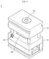
- FIG. 1 is a perspective view of a general mold having a built-in counter to which an electronic counter device configured to count a number of press-fittings for a mold according to an embodiment of the present invention is applied.
- a mold 10 includes an upper mold 12 and a lower mold 14.
- a resin injection hole 16 is provided at a top end of the upper mold 12, and a cavity 18 is formed on a top surface of the lower mold 12.
- a cavity may also be formed on a bottom surface of the upper mold 12.
- the electronic mold counter device 100 may be installed in the lower mold 14.
- the electronic mold counter device 100 is configured to count a number of times a mold is used, that is, a mold is press-fitted, when the upper mold 12 is moved toward the lower mold 14.
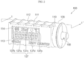
- FIG. 2 is a perspective view of an electronic mold counter device according to an embodiment of the present invention
- FIG. 3 is an exploded perspective view of an electronic mold counter device according to an embodiment of the present invention
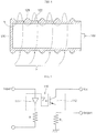
- FIG. 4 is a cross-sectional view of the electronic mold counter device taken along the line I-I' of FIG. 2
- FIG. 5 is a circuit view illustrating an example of optical detection using an optical detection unit shown in FIG. 2
- FIG. 6 is a block diagram schematically illustrating an electronic mold counter device according to an embodiment of the present invention and a mold production amount count system using the same.
- the electronic mold counter device 100 includes first and second cases 110 and 120 and a counting unit C.
- the first and second cases 110 and 120 are mounted on the mold and the counting unit C is accommodated therein.
- the first and second cases 110 and 120 are substantially shaped of a cylinder formed by combining the first case 110 with the second case 120.
- a stepped portion 111b is formed at a combined region of the outer circumferential surface of the first case 110, and a stepped portion receiving portion 121b shaped to correspond to the stepped portion 111b is formed in the second case 120.
- a protruding portion 116a is formed on a first side surface 116 of lengthwise opposite side surfaces of the first case 110 and a coupling groove 124a into which the protruding portion 116a is fitted is formed on a third side surface 124 corresponding to the first side surface 116 of lengthwise opposite side surfaces of the second case 120.
- a receiving portion 111a is vertically formed on an inner sidewall of the first case 110, and at least one vertical protruding portion 121a corresponding to the receiving portion 111a and fitted into the receiving portion 111a is formed on an inner sidewall of the second case 120.
- At least one supporting portion 121c for supporting the first case 110 and the second case 120 when they are combined with each other is formed in the second case 120.
- the first case 110 and the second case 120 may be relatively tightly coupled to each other, compared to the conventional coupling method using a bolt.
- a transparent window 114 is formed on the outer circumferential surface of the first case 110 to read internal figures from the outside.
- the window 114 is formed by forming an opening on the outer circumferential surface of the first case 110 and fixing a flat panel on the opening.
- the first case 110 has a switching hole 117 formed on a region adjacent to the window 114, the switching hole 117 allowing a switching unit 133 turning on/off the operation of the counting unit C to be described later to pass through.
- shaft through-hole 115a and 123a are formed on a second side surface 115 opposite to the first side surface 116 of the first case 110 and a fourth side surface 123 opposite to the third side surface 124 of the second case 120 to allow a shaft 161 of an elastic member 160 to be described later to linearly move to/from the outside and inside of the first and second cases 110 and 120.
- each of the first case 110 and the second case 120 has a substantially hemispherical cross-section in a lengthwise direction.
- the outer circumferential surface of the first case 110 may have a predetermined region that is flatly formed according to the shape of the counting unit C disposed inside the first case 110, but the present invention does not limit the shapes of the first case 110 and the second case 120 to that stated herein.
- the first and second cases 110 and 120 may further include heat dissipating units 112 and 122 spaced a predetermined distance apart from each other to surround external surfaces of the first and second cases 110 and 120.
- a ceramic pigment including finely powdered tourmaline emitting negative ions and far infrared rays may be coated on exteriors of the heat dissipating units 112 and 122 (more specifically, outer surfaces of the heat dissipating units 112 and 122 exposed to the outside of the mold).
- vertically sectional shapes of the heat dissipating units 112 and 122 may be a triangle, a rectangle, or a circle, but the present invention does not limit the sectional shapes of the heat dissipating units 112 and 122 to those stated herein.
- a mechanical counter device capable of withstanding a high temperature has been used.
- the heat dissipating units 112 and 122 are formed on outer surfaces of the first and second cases 110 and 120 accommodating the counting unit C to protect the counting unit C from high temperature.
- high-temperature air H flowing to the outside of the first and second cases 110 and 120 through the heat dissipating units 112 and 122 is allowed to flow through a gap between the heat dissipating units 112 and 122, thereby dissipating the heat. Accordingly, the counting unit C provided inside the first and second cases 110 and 120 can be safely protected from the high-temperature air H flowing to the outside of the first and second cases 110 and 120.
- the counting unit C is disposed inside the first and second cases 110 and 120 and counts the number of press-fittings for the mold.
- the counting unit C includes a printed circuit board 130, an optical detection unit 140, a power supply unit 150 and an elastic member 160.
- the printed circuit board 130 includes a calculation unit 132 which counts the insertion operation of the detected elastic member 160 according to the press-fittings of the mold as the number of press-fittings for the mold.
- the calculation unit 132 counts the corresponding detection signal as the number of press-fittings for the mold.
- the printed circuit board 130 further includes a communication unit 135, a temperature measurement unit 136, a display unit 137 and a control unit 134.
- the communication unit 135 transmits the number of press-fittings for the mold, counted by the calculation unit 132, to an external device through a communication network.
- the communication unit 135 transmits information on the number of press-fittings for the mold, information on a mold temperature, information on a power supply state of the power supply unit 150, information on a shorted state of the optical detection unit 140, and so on.
- the communication unit 135, including an interface 113 enabling wired/wireless communication transmits the information on the number of press-fittings for the mold to an external device, such as a control management server, through a wired/wireless communication terminal. Accordingly, the user can efficiently control the electronic counter device according to the present invention from a remote location.
- the temperature measurement unit 136 measures the temperature of the mold outside the first and second cases 110 and 120.
- the temperature measurement unit 136 is a sensor that measures the temperature of the mold, and the information on the measured temperature sensed by the sensor is transmitted to the control unit 134 to display the information on the display unit 137 or transmitted to the external device through the communication unit 135.
- the display unit 137 displays the number 137a of press-fittings for the mold, counted by the calculation unit 132.
- the number 137a of press-fittings for the mold may be accumulated and counted in real time.
- conductive lines 138 corresponding to the number of figures are connected to the calculation unit 132.
- the display unit 137 may display the supply state and power remainder amount information 137b of the power supply unit 150, the shorted state information 137c of the optical detection unit 140, the mold temperature information 137d and the communication state information 137e of the communication unit 135 to the outside of the case.
- the control unit 134 controls operations of the optical detection unit 140, the calculation unit 132, the communication unit 135, the temperature measurement unit 136 and the display unit 137.
- the control unit 134 may set and control a counting time range of the calculation unit 132 and a transmission time range of the communication unit 135. That is to say, the control unit 134 appropriately sets the counting time range of the calculation unit 132, thereby preventing an operational error of the calculation unit 132, that is, a counting error.
- the counting time range of the calculation unit 132 may refer to a time range in which the insertion operation of the elastic member 160 is detected.
- control unit 134 sets the transmission time range of the communication unit 135 to a predetermined period, and may transmit information on the number of press-fittings for the mold, information on a mold temperature, information on a power supply state of the power supply unit 150, information on a shorted state of the optical detection unit 140, and so on, to the external device in a periodical, stable manner.
- the power supply unit 150 supplies power to the counting unit C including the control unit 134.
- the power supply unit 150 may use one of a secondary battery, alternating current power and a solar cell. That is to say, externally supplied power may be used at a place where power supply is available, and a secondary battery or a battery charged using a solar cell to refill discharge power and to directly supply power may be used at a place where power supply is not available.
- the secondary battery is illustrated by way of example.
- the power supply unit 150 is installed to be fixed to a bottom portion of the plate 142 of the optical detection unit 140 to supply power to the control unit 134 of the printed circuit board 130 installed on the plate 142 through a predetermined conductive line (not shown).
- the elastic member 160 includes the shaft 161 protruding so as to pass through the shaft through-hole 115a and 123a and is designed such that the shaft 161 is inserted into the first and second cases 110 and 120 by an elastic force applied when the mold is press-fitted.
- the elastic member 160 includes a spring 170 as well as the shaft 161.
- the spring 170 has an elastic force and is fixed to the inside of the first and second cases 110 and 120. More specifically, the spring 170 is fixed to the fixing plate 167 vertically fixedly installed on the bottom surface of the plate 142 of the optical detection unit 140.
- the fixing plate 167 has a shaft fixing panel 166 installed on its surface to fix the shaft 161.
- the shaft 161 vertically extends from the shaft fixing panel 166 and is installed to pass through the inside of the spring 170. More specifically, the shaft 161 includes a fixing ring 165 coupled to the shaft fixing panel 166, a first guide bar 164 extending from the shaft fixing panel 166 in a lengthwise direction of the spring 170 and a second guide bar 162 including a vertical bar 163 extending and protruding from the first guide bar 164 in its lengthwise direction.
- the vertical bar 163 is formed to protrude to the exterior side relative to the outer circumferential edge of the spring 170.
- the vertical bar 163 is formed to have a thickness smaller than a width of an insertion hole 141 of the optical detection unit 140 so as to be inserted into the insertion hole 141.
- the afore-constructed shaft 161 linearly moves in a lengthwise direction of the spring 170 according to the pres-fittings of the mold to pass through the inside of the spring 170. Specifically, the shaft 161 moves to allow the vertical bar 163 to be inserted into the insertion hole 141 of the optical detection unit 140.
- the optical detection unit 140 irradiates light into the elastic member 160 inserted into the first and second cases 110 and 120 and detects insertion of the elastic member 160.
- the optical detection unit 140 includes an emitting part 131a, a receiving part 131b, and a plate 142.
- the emitting part 131a and the receiving part 131b are spaced a predetermined distance apart from each other and are disposed to face each other.
- the emitting part 131a and the receiving part 131b are fixedly installed on the plate 142 through a conductive fixing lead 131c to allow the insertion hole 141 formed in the plate 142 to be positioned therebetween.
- the thus formed emitting part 131a and receiving part 131b are electrically connected to the printed circuit board 130 to be described later by a separate conductive line (not shown) connected to the fixing lead 131c.
- the emitting part 131a and the receiving part 131b may be configured by photo-interrupt circuits.
- the emitting part 131a may be implemented by a light emitting diode
- the receiving part 131b may be implemented by an npn type circuit including a photo transistor.
- the vertical bar 163 of the shaft 161 is not inserted into the insertion hole 141 of the plate 142, light is received from the light emitting diode as the emitting part 131a to the photo transistor as the receiving part 131b and the photo transistor is turned on. Then, a current does not flow to an output port connected to a collector terminal of the photo transistor.
- the vertical bar 163 of the shaft 161 is inserted into the insertion hole 141 of the plate 142, light is blocked from the light emitting diode as the emitting part 131a to the photo transistor as the receiving part 131b and a current flows to an output port connected to a collector terminal of the photo transistor through a load resistor R L . Therefore, when the shaft 161 is inserted into the insertion hole 141, the emitting part 131a and the receiving part 131b may transmit a current signal corresponding to the flowing current to the calculation unit 132 to be described later.
- the plate 142 is flatly formed to be fixed to the inside of the first and second cases 110 and 120 and is disposed to be spaced apart from the printed circuit board 130 to be described later.
- the plate 142 includes the insertion hole 141 formed between the emitting part 131a and the receiving part 131b.
- the optical detection unit 131 detects the insertion of the vertical bar 163 and the calculation unit 132 counts the number of insertion operations detected, thereby electronically and automatically counting the number of press-fittings for the mold.
- the mold production amount count system using the electronic mold counter device includes the electronic mold counter device 100 shown in FIGS. 2 to 5 , and a control management unit 300 controlling the operation of the electronic mold counter device 100 using measurement values of measured items transmitted through the electronic mold counter device 100 and the communication terminal 200 in a wired/wireless manner in real time.
- the measured items transmitted in real time may include information on the number of press-fittings for the mold, transmitted from the communication unit 135 provided in the electronic mold counter device 100, information on a mold temperature, information on a power supply state of the power supply unit 150, information on a shorted state of the optical detection unit 140, and so on.
- the control management unit 300 may include a user interface (UI) and software such as a database management system (DBMS).
- UI user interface
- DBMS database management system
- the user may monitor the information on the measurement data of the electronic mold counter device 100 according to the present invention through the software of the control management unit 300, and can efficiently manage the electronic mold counter device according to the present invention from a remote location based on the information.
Landscapes
- Engineering & Computer Science (AREA)
- Physics & Mathematics (AREA)
- General Physics & Mathematics (AREA)
- Theoretical Computer Science (AREA)
- Manufacturing & Machinery (AREA)
- Mechanical Engineering (AREA)
- Moulds For Moulding Plastics Or The Like (AREA)
- Switches Operated By Changes In Physical Conditions (AREA)
- Injection Moulding Of Plastics Or The Like (AREA)
Description
- An embodiment of the present invention relates to an electronic mold counter device.
- Since a mold has a lowered accuracy after the repeated use for a prolonged period of time, the accuracy of a mold is lowered and it is necessary to use the mold by a predetermined number of times.
- In this regard, a mold counter, called a shot counter, is incorporated into the mold to be used. The mold counter is configured to mechanically count the number of press-fittings for the mold, that is, a mold is used, by rotating a plurality of figure rings using a plurality of rotating plates.
- However, the conventional mold counter has the following problems.
- First, since the mold having a plate weak in mechanical strength may be deformed while being repeatedly press-fitted, the mold counter may malfunction.
- In addition, since the plate is separately formed from a shaft, the production cost may increase.
- Further, in a case where the counter has small-sized figure rings and figures, resulting in a dark screen, and is covered by dust, it is difficult to recognize the figures.
- In addition, a conventional mechanical mold counter is managed in such a mechanically manual manner that cumulative counted values are identified by naked eye and managed. Thus, there is a high probability of generating an error due to an operator's mistake.
- Further, in the conventional mechanical mold counter, costs incurred by oil change or poor management of production shortage of injected articles may increase, lowering management efficiency and product quality.
-
US 5571539 A shows an electronic counter device according to the preamble ofclaim 1. -
US 2010/320632 A1 discloses a monitor for maintaining a mold cycle count with an actuator sending a count signal to a processor following a mold operation. The monitor further includes a timer having an active mode and a sleep mode. The processor generates an average cycle time and an activity percentage of the mold taking into account active and sleep periods of the mold. - It is an object of the invention to provide an electronic counter device configured to count a number of press-fittings for a mold, which allows higher working efficiency and improves heat dissipating characteristic of the counter device.
- In order to overcome the above-mentioned shortcomings, the present invention defined by
claim 1 provides an electronic counter device configured to count a number of press-fittings for a mold which uses an optical detection method to automatically count the mold production amount in a set time for higher working efficiency. - As described above, the electronic mold counter device according to the present invention uses an optical detection method, thereby automatically counting the mold production amount in a set time for higher working efficiency.
- In addition, in the electronic mold counter device according to the present invention, heat dissipating units are provided outside a case of the counter device, thereby improving heat dissipating characteristic of the counter device.
- The objects, features and advantages of the present invention will be more apparent from the following detailed description in conjunction with the accompanying drawings, in which:
-
FIG. 1 is a perspective view of a general mold having a built-in counter to which an electronic mold counter device according to an embodiment of the present invention is applied; -
FIG. 2 is a perspective view of an electronic mold counter device according to an embodiment of the present invention; -
FIG. 3 is an exploded perspective view of an electronic mold counter device according to an embodiment of the present invention; -
FIG. 4 is a cross-sectional view of the electronic mold counter device taken along the line I-I' ofFIG. 2 ; -
FIG. 5 is a circuit view illustrating an example of optical detection using an optical detection unit shown inFIG. 2 ; and -
FIG. 6 is a block diagram schematically illustrating an electronic mold counter device according to an embodiment of the present invention and a mold production amount count system using the same. - Example embodiments of the present invention will now be described in more detail with reference to accompanying drawings, such that those skilled in the art can easily practice the present invention.
-
FIG. 1 is a perspective view of a general mold having a built-in counter to which an electronic counter device configured to count a number of press-fittings for a mold according to an embodiment of the present invention is applied. - Referring to
FIG. 1 , amold 10 includes anupper mold 12 and alower mold 14. Aresin injection hole 16 is provided at a top end of theupper mold 12, and a cavity 18 is formed on a top surface of thelower mold 12. Although not shown, a cavity may also be formed on a bottom surface of theupper mold 12. - Meanwhile, the electronic
mold counter device 100 according to the embodiment of the present invention may be installed in thelower mold 14. The electronicmold counter device 100 is configured to count a number of times a mold is used, that is, a mold is press-fitted, when theupper mold 12 is moved toward thelower mold 14. - Hereinafter, an electronic mold counter device incorporated into the mold will now be described with reference to
FIGS. 2 to 6 . -
FIG. 2 is a perspective view of an electronic mold counter device according to an embodiment of the present invention,FIG. 3 is an exploded perspective view of an electronic mold counter device according to an embodiment of the present invention,FIG. 4 is a cross-sectional view of the electronic mold counter device taken along the line I-I' ofFIG. 2 ,FIG. 5 is a circuit view illustrating an example of optical detection using an optical detection unit shown inFIG. 2 , andFIG. 6 is a block diagram schematically illustrating an electronic mold counter device according to an embodiment of the present invention and a mold production amount count system using the same. - Referring to
FIGS. 2 to 6 , the electronicmold counter device 100 according to the embodiment of the present invention includes first andsecond cases - The first and
second cases second cases first case 110 with thesecond case 120. In order to combine thefirst case 110 with thesecond case 120, astepped portion 111b is formed at a combined region of the outer circumferential surface of thefirst case 110, and a steppedportion receiving portion 121b shaped to correspond to thestepped portion 111b is formed in thesecond case 120. In addition, in order to combine thefirst case 110 with thesecond case 120, aprotruding portion 116a is formed on afirst side surface 116 of lengthwise opposite side surfaces of thefirst case 110 and acoupling groove 124a into which theprotruding portion 116a is fitted is formed on athird side surface 124 corresponding to thefirst side surface 116 of lengthwise opposite side surfaces of thesecond case 120. In addition, areceiving portion 111a is vertically formed on an inner sidewall of thefirst case 110, and at least onevertical protruding portion 121a corresponding to thereceiving portion 111a and fitted into thereceiving portion 111a is formed on an inner sidewall of thesecond case 120. In addition, at least one supportingportion 121c for supporting thefirst case 110 and thesecond case 120 when they are combined with each other is formed in thesecond case 120. With this configuration, thefirst case 110 and thesecond case 120 may be relatively tightly coupled to each other, compared to the conventional coupling method using a bolt. - In addition, a
transparent window 114 is formed on the outer circumferential surface of thefirst case 110 to read internal figures from the outside. Thewindow 114 is formed by forming an opening on the outer circumferential surface of thefirst case 110 and fixing a flat panel on the opening. In addition, thefirst case 110 has aswitching hole 117 formed on a region adjacent to thewindow 114, theswitching hole 117 allowing aswitching unit 133 turning on/off the operation of the counting unit C to be described later to pass through. - In addition, shaft through-
hole second side surface 115 opposite to thefirst side surface 116 of thefirst case 110 and afourth side surface 123 opposite to thethird side surface 124 of thesecond case 120 to allow ashaft 161 of anelastic member 160 to be described later to linearly move to/from the outside and inside of the first andsecond cases - Meanwhile, each of the
first case 110 and thesecond case 120 has a substantially hemispherical cross-section in a lengthwise direction. However, the outer circumferential surface of thefirst case 110 may have a predetermined region that is flatly formed according to the shape of the counting unit C disposed inside thefirst case 110, but the present invention does not limit the shapes of thefirst case 110 and thesecond case 120 to that stated herein. - The first and
second cases heat dissipating units
surfaces of the first andsecond cases heat dissipating units 112 and 122 (more specifically, outer surfaces of theheat dissipating units - Referring to
FIG. 4 , vertically sectional shapes of theheat dissipating units heat dissipating units second cases heat dissipating units second cases second cases heat dissipating units heat dissipating units second cases second cases - The counting unit C is disposed inside the first and
second cases circuit board 130, anoptical detection unit 140, apower supply unit 150 and anelastic member 160. - The printed
circuit board 130 includes acalculation unit 132 which counts the insertion operation of the detectedelastic member 160 according to the press-fittings of the mold as the number of press-fittings for the mold. When the insertion of theelastic member 160 into the first andsecond cases optical detection unit 140, thecalculation unit 132 counts the corresponding detection signal as the number of press-fittings for the mold. - In addition to the
calculation unit 132, the printedcircuit board 130 further includes a communication unit 135, a temperature measurement unit 136, adisplay unit 137 and acontrol unit 134. - The communication unit 135 transmits the number of press-fittings for the mold, counted by the
calculation unit 132, to an external device through a communication network. In addition, the communication unit 135 transmits information on the number of press-fittings for the mold, information on a mold temperature, information on a power supply state of thepower supply unit 150, information on a shorted state of theoptical detection unit 140, and so on. The communication unit 135, including aninterface 113 enabling wired/wireless communication, transmits the information on the number of press-fittings for the mold to an external device, such as a control management server, through a wired/wireless communication terminal. Accordingly, the user can efficiently control the electronic counter device according to the present invention from a remote location. - The temperature measurement unit 136 measures the temperature of the mold outside the first and
second cases control unit 134 to display the information on thedisplay unit 137 or transmitted to the external device through the communication unit 135. - The
display unit 137 displays thenumber 137a of press-fittings for the mold, counted by thecalculation unit 132. Thenumber 137a of press-fittings for the mold may be accumulated and counted in real time. As described above, in order to display thenumber 137a of press-fittings for the mold,conductive lines 138 corresponding to the number of figures are connected to thecalculation unit 132. In addition, thedisplay unit 137 may display the supply state and powerremainder amount information 137b of thepower supply unit 150, the shortedstate information 137c of theoptical detection unit 140, themold temperature information 137d and thecommunication state information 137e of the communication unit 135 to the outside of the case. - The
control unit 134 controls operations of theoptical detection unit 140, thecalculation unit 132, the communication unit 135, the temperature measurement unit 136 and thedisplay unit 137. In particular, thecontrol unit 134 may set and control a counting time range of thecalculation unit 132 and a transmission time range of the communication unit 135. That is to say, thecontrol unit 134 appropriately sets the counting time range of thecalculation unit 132, thereby preventing an operational error of thecalculation unit 132, that is, a counting error. Here, the counting time range of thecalculation unit 132 may refer to a time range in which the insertion operation of theelastic member 160 is detected. In addition, thecontrol unit 134 sets the transmission time range of the communication unit 135 to a predetermined period, and may transmit information on the number of press-fittings for the mold, information on a mold temperature, information on a power supply state of thepower supply unit 150, information on a shorted state of theoptical detection unit 140, and so on, to the external device in a periodical, stable manner. - The
power supply unit 150 supplies power to the counting unit C including thecontrol unit 134. Here, thepower supply unit 150 may use one of a secondary battery, alternating current power and a solar cell. That is to say, externally supplied power may be used at a place where power supply is available, and a secondary battery or a battery charged using a solar cell to refill discharge power and to directly supply power may be used at a place where power supply is not available. - In the present invention, the secondary battery is illustrated by way of example. Here, the
power supply unit 150 is installed to be fixed to a bottom portion of theplate 142 of theoptical detection unit 140 to supply power to thecontrol unit 134 of the printedcircuit board 130 installed on theplate 142 through a predetermined conductive line (not shown). - The
elastic member 160 includes theshaft 161 protruding so as to pass through the shaft through-hole shaft 161 is inserted into the first andsecond cases elastic member 160 includes aspring 170 as well as theshaft 161. Thespring 170 has an elastic force and is fixed to the inside of the first andsecond cases spring 170 is fixed to the fixingplate 167 vertically fixedly installed on the bottom surface of theplate 142 of theoptical detection unit 140. The fixingplate 167 has ashaft fixing panel 166 installed on its surface to fix theshaft 161. Theshaft 161 vertically extends from theshaft fixing panel 166 and is installed to pass through the inside of thespring 170. More specifically, theshaft 161 includes a fixingring 165 coupled to theshaft fixing panel 166, afirst guide bar 164 extending from theshaft fixing panel 166 in a lengthwise direction of thespring 170 and asecond guide bar 162 including avertical bar 163 extending and protruding from thefirst guide bar 164 in its lengthwise direction. Thevertical bar 163 is formed to protrude to the exterior side relative to the outer circumferential edge of thespring 170. In addition, thevertical bar 163 is formed to have a thickness smaller than a width of aninsertion hole 141 of theoptical detection unit 140 so as to be inserted into theinsertion hole 141. - The afore-constructed
shaft 161 linearly moves in a lengthwise direction of thespring 170 according to the pres-fittings of the mold to pass through the inside of thespring 170. Specifically, theshaft 161 moves to allow thevertical bar 163 to be inserted into theinsertion hole 141 of theoptical detection unit 140. - The
optical detection unit 140 irradiates light into theelastic member 160 inserted into the first andsecond cases elastic member 160. In order to implement the detection operation, theoptical detection unit 140 includes anemitting part 131a, a receivingpart 131b, and aplate 142. - The emitting
part 131a and the receivingpart 131b are spaced a predetermined distance apart from each other and are disposed to face each other. Preferably, the emittingpart 131a and the receivingpart 131b are fixedly installed on theplate 142 through a conductive fixing lead 131c to allow theinsertion hole 141 formed in theplate 142 to be positioned therebetween. The thus formed emittingpart 131a and receivingpart 131b are electrically connected to the printedcircuit board 130 to be described later by a separate conductive line (not shown) connected to the fixinglead 131c. Referring toFIG. 5 , the emittingpart 131a and the receivingpart 131b may be configured by photo-interrupt circuits. That is to say, the emittingpart 131a may be implemented by a light emitting diode, and the receivingpart 131b may be implemented by an npn type circuit including a photo transistor. For example, if thevertical bar 163 of theshaft 161 is not inserted into theinsertion hole 141 of theplate 142, light is received from the light emitting diode as the emittingpart 131a to the photo transistor as the receivingpart 131b and the photo transistor is turned on. Then, a current does not flow to an output port connected to a collector terminal of the photo transistor. - On the other hand, if the
vertical bar 163 of theshaft 161 is inserted into theinsertion hole 141 of theplate 142, light is blocked from the light emitting diode as the emittingpart 131a to the photo transistor as the receivingpart 131b and a current flows to an output port connected to a collector terminal of the photo transistor through a load resistor RL. Therefore, when theshaft 161 is inserted into theinsertion hole 141, the emittingpart 131a and the receivingpart 131b may transmit a current signal corresponding to the flowing current to thecalculation unit 132 to be described later. - The
plate 142 is flatly formed to be fixed to the inside of the first andsecond cases circuit board 130 to be described later. In addition, theplate 142 includes theinsertion hole 141 formed between the emittingpart 131a and the receivingpart 131b. - Therefore, in the present invention, when the
vertical bar 163 of theshaft 161 is inserted into theinsertion hole 141 of theplate 142 according to the press-fitting of the mold, theoptical detection unit 131 detects the insertion of thevertical bar 163 and thecalculation unit 132 counts the number of insertion operations detected, thereby electronically and automatically counting the number of press-fittings for the mold. - Referring to
FIG. 6 , the mold production amount count system using the electronic mold counter device according to an embodiment of the present invention includes the electronicmold counter device 100 shown inFIGS. 2 to 5 , and acontrol management unit 300 controlling the operation of the electronicmold counter device 100 using measurement values of measured items transmitted through the electronicmold counter device 100 and thecommunication terminal 200 in a wired/wireless manner in real time. Here, the measured items transmitted in real time may include information on the number of press-fittings for the mold, transmitted from the communication unit 135 provided in the electronicmold counter device 100, information on a mold temperature, information on a power supply state of thepower supply unit 150, information on a shorted state of theoptical detection unit 140, and so on. Here, thecontrol management unit 300 may include a user interface (UI) and software such as a database management system (DBMS). - Therefore, the user may monitor the information on the measurement data of the electronic
mold counter device 100 according to the present invention through the software of thecontrol management unit 300, and can efficiently manage the electronic mold counter device according to the present invention from a remote location based on the information. - Although the electronic mold counter device according to an exemplary embodiment of the present invention has been described in detail hereinabove, it should be understood that many variations and modifications of the basic inventive concept herein described, which may appear to those skilled in the art, will still fall within the scope of the exemplary embodiments of the present invention as defined by the appended claims.
Claims (5)
- An electronic counter device configured to count a number of press-fittings for a mold (10), comprising:a case (110, 120) mounted on the mold (10) and having a shaft through-hole (115a, 123a) on one side thereof; anda counting unit disposed inside the case to count the number of press-fittings for the mold (10),wherein the counting unit comprises:an elastic member (160) which comprises a spring (170) fixedly installed within the case and a shaft (161) adapted to penetrate the shaft through-hole (115a, 123a) of the case (110, 120) and thereby to protrude, anda calculation unit (132) adapted to count the insertion operation of the elastic member (160) as the number of press-fittings for the mold,characterized in that the shaft (161) includes a bar (163) protruding on an outer circumferential edge, and is disposed to pass through the inside of the spring (170) by a linear movement in a lengthwise direction of the spring (170) so as to move to allow the bar (163) to be positioned to be adjacent to the optical detection unit (140) when the mold is press-fitted;
that the counting unit further comprises an optical detection unit (140) adapted to irradiate the inserted elastic member (160) with light to detect the insertion operation of the elastic member (160); and
that the case (110, 120) further includes heat-dissipating units (112, 122) spaced a predetermined distance apart from each other and protruding to surround an external surface of the case. - The electronic counter device of claim 1, wherein the optical detection unit (140) comprises:an emitting part (131a) adapted to emit light;a receiving part (131b) spaced a predetermined distance apart from the emitting part (131a), disposed to face the emitting part (131a) and receiving the light; anda plate (142) having the emitting part (131a) and the receiving part (131b) installed on its surface and an insertion hole (144) provided at a region between the emitting part (131a) and the receiving part (131b).
- The electronic counter device of claim 2, wherein the device is configured to allow the bar (163) to be inserted into the insertion hole (141), and the calculation unit (132) is adapted to count the number of times the emitting part (131a) emits light to the bar (163) inserted into the insertion hole (141) according to the press-fitting of the mold and the receiving part (131b) cannot receive the emitted light as the number of press-fittings for the mold.
- The electronic counter device of claim 2 or 3, wherein the calculation unit (132) is formed on a printed circuit board (130), and the printed circuit board (130) is formed on the plate (142) and further includes a display unit (137) adapted to display the number of press-fittings for the mold, counted in the calculation unit (132); a communication unit (135) adapted to transmit the number of press-fittings for the mold, counted in the calculation unit (132) to an external device through a communication network; and a controller controlling operations of the optical detection unit, the calculation unit (132), the display unit (137) and the communication unit (135) to set and control a counting time range of the calculation unit (132) and a transmission time range of the communication unit (135).
- The electronic counter device of claim 4, wherein the printed circuit board (130) further includes a temperature measurement unit (136) adapted to measure a temperature of the mold outside the case, and the counting unit further includes a power supply unit (150) adapted to supply power, wherein the display unit (137) is adapted to display information on the temperature of the mold, measured by the temperature measurement unit (136) and information on a power supply state of the power supply unit (150) and a power remainder amount.
Applications Claiming Priority (2)
| Application Number | Priority Date | Filing Date | Title |
|---|---|---|---|
| KR20110137762A KR101183283B1 (en) | 2011-12-19 | 2011-12-19 | Electronic counter device of mold |
| PCT/KR2012/011013 WO2013094948A1 (en) | 2011-12-19 | 2012-12-17 | Electronic mold counter device |
Publications (3)
| Publication Number | Publication Date |
|---|---|
| EP2797037A1 EP2797037A1 (en) | 2014-10-29 |
| EP2797037A4 EP2797037A4 (en) | 2015-09-02 |
| EP2797037B1 true EP2797037B1 (en) | 2019-02-06 |
Family
ID=47113620
Family Applications (1)
| Application Number | Title | Priority Date | Filing Date |
|---|---|---|---|
| EP12860304.0A Not-in-force EP2797037B1 (en) | 2011-12-19 | 2012-12-17 | Electronic mold counter device |
Country Status (6)
| Country | Link |
|---|---|
| EP (1) | EP2797037B1 (en) |
| KR (1) | KR101183283B1 (en) |
| CN (1) | CN104137125B (en) |
| ES (1) | ES2718663T3 (en) |
| MX (1) | MX339892B (en) |
| WO (1) | WO2013094948A1 (en) |
Families Citing this family (13)
| Publication number | Priority date | Publication date | Assignee | Title |
|---|---|---|---|---|
| CN106682724A (en) * | 2016-10-10 | 2017-05-17 | 上海智引信息科技有限公司 | Counter for monitoring reciprocating tool, counting method and mould |
| CN109859344B (en) * | 2017-11-30 | 2021-06-25 | 青岛海尔智能技术研发有限公司 | A kind of intelligent monitoring method and intelligent management system of mold |
| CN110751147A (en) * | 2018-07-24 | 2020-02-04 | 林哲安 | Counting method in mold production process |
| CN110889485B (en) * | 2019-10-22 | 2022-05-17 | 浙江工商职业技术学院 | Counter mould |
| KR102268773B1 (en) * | 2020-05-04 | 2021-06-24 | 주식회사 라디언트 | Self recharging mold counter |
| KR102268911B1 (en) * | 2020-05-04 | 2021-06-24 | 주식회사 휴앤파워 | Mold counter |
| KR102266747B1 (en) | 2020-08-11 | 2021-06-21 | 피에스텍 주식회사 | Mold counter Mold management system |
| CN112116056A (en) * | 2020-09-17 | 2020-12-22 | 重庆盟讯电子科技有限公司 | A turnover car for counting PCBA board and being used for storing PCBA board |
| KR102217378B1 (en) | 2020-09-29 | 2021-02-18 | 주식회사 디씨알 | Smart Vibration Counting Device |
| KR102235243B1 (en) | 2020-11-11 | 2021-04-02 | 주식회사 디씨알 | Smart Vibration Analyzing Device |
| KR102521916B1 (en) | 2021-04-15 | 2023-04-14 | 김현호 | Digital mold counter and management system having the same |
| KR102491705B1 (en) | 2021-09-07 | 2023-01-27 | 이영화 | Injection molding processing monitoring system and method |
| KR102895066B1 (en) | 2023-01-18 | 2025-12-04 | 주식회사 이몰디노 | Sensor module for press molding process monitoring |
Family Cites Families (11)
| Publication number | Priority date | Publication date | Assignee | Title |
|---|---|---|---|---|
| SU752410A1 (en) * | 1978-10-30 | 1980-07-30 | Предприятие П/Я А-1575 | Article counting device |
| JP2589420Y2 (en) * | 1993-11-29 | 1999-01-27 | 株式会社田村電機製作所 | Electromagnetic counter |
| US5571539A (en) * | 1994-12-30 | 1996-11-05 | D & L Incorporated | Mold with an on-board counter or monitor |
| KR20070093671A (en) * | 2006-03-15 | 2007-09-19 | 김재만 | Information storage and confirmation device of mold |
| CN201069579Y (en) * | 2007-08-28 | 2008-06-04 | 沈建锋 | A mould counter |
| CN201146198Y (en) * | 2007-12-20 | 2008-11-05 | 黄建平 | Minisize thread-wearing machine |
| JP5207784B2 (en) * | 2008-03-11 | 2013-06-12 | 富士通コンポーネント株式会社 | Input device |
| CN201455103U (en) * | 2009-06-02 | 2010-05-12 | 鹤壁海昌专用设备有限公司 | Counting cut-off type crimping die |
| CA2764843C (en) * | 2009-06-18 | 2015-07-28 | Progressive Components International Corporation | Electronic cycle counter |
| CN102233776B (en) * | 2010-05-04 | 2013-07-10 | 哈尔滨建成集团有限公司 | Continuous counting lettering mold capable of realizing self instructed carry |
| KR101045286B1 (en) * | 2010-07-26 | 2011-06-29 | (주)대영오앤이 | Apparatus for divided rotation of driving dial of short counter |
-
2011
- 2011-12-19 KR KR20110137762A patent/KR101183283B1/en active Active
-
2012
- 2012-12-17 WO PCT/KR2012/011013 patent/WO2013094948A1/en not_active Ceased
- 2012-12-17 ES ES12860304T patent/ES2718663T3/en active Active
- 2012-12-17 CN CN201280069353.6A patent/CN104137125B/en not_active Expired - Fee Related
- 2012-12-17 EP EP12860304.0A patent/EP2797037B1/en not_active Not-in-force
- 2012-12-17 MX MX2014007390A patent/MX339892B/en active IP Right Grant
Non-Patent Citations (1)
| Title |
|---|
| None * |
Also Published As
| Publication number | Publication date |
|---|---|
| EP2797037A4 (en) | 2015-09-02 |
| MX2014007390A (en) | 2015-03-06 |
| KR101183283B1 (en) | 2012-09-14 |
| WO2013094948A1 (en) | 2013-06-27 |
| ES2718663T3 (en) | 2019-07-03 |
| MX339892B (en) | 2016-06-16 |
| CN104137125A (en) | 2014-11-05 |
| EP2797037A1 (en) | 2014-10-29 |
| CN104137125B (en) | 2017-05-10 |
Similar Documents
| Publication | Publication Date | Title |
|---|---|---|
| EP2797037A1 (en) | Electronic mold counter device | |
| KR102266747B1 (en) | Mold counter Mold management system | |
| US9279711B1 (en) | Optical sensor for a conventional tank gauge | |
| CN110061540B (en) | Power tool battery pack and system with wireless communication | |
| US20200147473A1 (en) | Impact sensing mouthguard | |
| TW201347344A (en) | Wireless power transfer via conductive material | |
| JP5776103B2 (en) | Intrusion detection device | |
| CN103606017B (en) | Clothes, shoes and hats try statistical method, system, report method and device on | |
| CN104700195A (en) | Article storage information display method and device | |
| CN209883635U (en) | Intelligent goods shelf system, intelligent warehousing system and supply chain monitoring system | |
| CN104573913B (en) | Pannier device, the method and apparatus for determining article storage state | |
| CN104732321A (en) | Article storage system and preservation method and device for article storage data | |
| US20220230725A1 (en) | Systems and methods for authenticating medical infusion lines | |
| CN211459363U (en) | Medicine cabinet | |
| CN104578337A (en) | Electric equipment placed in compartment of refrigerator and refrigerator | |
| KR102521916B1 (en) | Digital mold counter and management system having the same | |
| CN207424713U (en) | A kind of separated temperature controller | |
| CN209372187U (en) | A kind of paper amount detection sensing acquisition device | |
| CN217609724U (en) | Helmet wearing detection device structure | |
| CN223262874U (en) | Base station of sweeper and cleaning equipment | |
| US10032342B1 (en) | Storage apparatus with item count feature | |
| CN207690243U (en) | A kind of antitheft magnetic card machine transplanting of rice bayonet apparatus | |
| CN215338416U (en) | Warehouse temperature and humidity sensing device | |
| CN220855468U (en) | Electronic clock capable of improving human body induction stability of keys | |
| CN218097954U (en) | Water level detection mechanism and steam box |
Legal Events
| Date | Code | Title | Description |
|---|---|---|---|
| PUAI | Public reference made under article 153(3) epc to a published international application that has entered the european phase |
Free format text: ORIGINAL CODE: 0009012 |
|
| 17P | Request for examination filed |
Effective date: 20140715 |
|
| AK | Designated contracting states |
Kind code of ref document: A1 Designated state(s): AL AT BE BG CH CY CZ DE DK EE ES FI FR GB GR HR HU IE IS IT LI LT LU LV MC MK MT NL NO PL PT RO RS SE SI SK SM TR |
|
| DAX | Request for extension of the european patent (deleted) | ||
| RA4 | Supplementary search report drawn up and despatched (corrected) |
Effective date: 20150730 |
|
| RIC1 | Information provided on ipc code assigned before grant |
Ipc: G06M 1/10 20060101AFI20150724BHEP Ipc: B29C 45/17 20060101ALI20150724BHEP |
|
| STAA | Information on the status of an ep patent application or granted ep patent |
Free format text: STATUS: EXAMINATION IS IN PROGRESS |
|
| 17Q | First examination report despatched |
Effective date: 20171213 |
|
| GRAP | Despatch of communication of intention to grant a patent |
Free format text: ORIGINAL CODE: EPIDOSNIGR1 |
|
| STAA | Information on the status of an ep patent application or granted ep patent |
Free format text: STATUS: GRANT OF PATENT IS INTENDED |
|
| INTG | Intention to grant announced |
Effective date: 20180821 |
|
| GRAS | Grant fee paid |
Free format text: ORIGINAL CODE: EPIDOSNIGR3 |
|
| GRAA | (expected) grant |
Free format text: ORIGINAL CODE: 0009210 |
|
| STAA | Information on the status of an ep patent application or granted ep patent |
Free format text: STATUS: THE PATENT HAS BEEN GRANTED |
|
| AK | Designated contracting states |
Kind code of ref document: B1 Designated state(s): AL AT BE BG CH CY CZ DE DK EE ES FI FR GB GR HR HU IE IS IT LI LT LU LV MC MK MT NL NO PL PT RO RS SE SI SK SM TR |
|
| REG | Reference to a national code |
Ref country code: GB Ref legal event code: FG4D |
|
| REG | Reference to a national code |
Ref country code: CH Ref legal event code: EP Ref country code: AT Ref legal event code: REF Ref document number: 1095365 Country of ref document: AT Kind code of ref document: T Effective date: 20190215 |
|
| REG | Reference to a national code |
Ref country code: IE Ref legal event code: FG4D |
|
| REG | Reference to a national code |
Ref country code: DE Ref legal event code: R096 Ref document number: 602012056554 Country of ref document: DE |
|
| REG | Reference to a national code |
Ref country code: NL Ref legal event code: FP |
|
| REG | Reference to a national code |
Ref country code: LT Ref legal event code: MG4D |
|
| REG | Reference to a national code |
Ref country code: ES Ref legal event code: FG2A Ref document number: 2718663 Country of ref document: ES Kind code of ref document: T3 Effective date: 20190703 |
|
| PG25 | Lapsed in a contracting state [announced via postgrant information from national office to epo] |
Ref country code: LT Free format text: LAPSE BECAUSE OF FAILURE TO SUBMIT A TRANSLATION OF THE DESCRIPTION OR TO PAY THE FEE WITHIN THE PRESCRIBED TIME-LIMIT Effective date: 20190206 Ref country code: NO Free format text: LAPSE BECAUSE OF FAILURE TO SUBMIT A TRANSLATION OF THE DESCRIPTION OR TO PAY THE FEE WITHIN THE PRESCRIBED TIME-LIMIT Effective date: 20190506 Ref country code: FI Free format text: LAPSE BECAUSE OF FAILURE TO SUBMIT A TRANSLATION OF THE DESCRIPTION OR TO PAY THE FEE WITHIN THE PRESCRIBED TIME-LIMIT Effective date: 20190206 Ref country code: PT Free format text: LAPSE BECAUSE OF FAILURE TO SUBMIT A TRANSLATION OF THE DESCRIPTION OR TO PAY THE FEE WITHIN THE PRESCRIBED TIME-LIMIT Effective date: 20190606 Ref country code: SE Free format text: LAPSE BECAUSE OF FAILURE TO SUBMIT A TRANSLATION OF THE DESCRIPTION OR TO PAY THE FEE WITHIN THE PRESCRIBED TIME-LIMIT Effective date: 20190206 |
|
| REG | Reference to a national code |
Ref country code: AT Ref legal event code: MK05 Ref document number: 1095365 Country of ref document: AT Kind code of ref document: T Effective date: 20190206 |
|
| PG25 | Lapsed in a contracting state [announced via postgrant information from national office to epo] |
Ref country code: IS Free format text: LAPSE BECAUSE OF FAILURE TO SUBMIT A TRANSLATION OF THE DESCRIPTION OR TO PAY THE FEE WITHIN THE PRESCRIBED TIME-LIMIT Effective date: 20190606 Ref country code: LV Free format text: LAPSE BECAUSE OF FAILURE TO SUBMIT A TRANSLATION OF THE DESCRIPTION OR TO PAY THE FEE WITHIN THE PRESCRIBED TIME-LIMIT Effective date: 20190206 Ref country code: HR Free format text: LAPSE BECAUSE OF FAILURE TO SUBMIT A TRANSLATION OF THE DESCRIPTION OR TO PAY THE FEE WITHIN THE PRESCRIBED TIME-LIMIT Effective date: 20190206 Ref country code: GR Free format text: LAPSE BECAUSE OF FAILURE TO SUBMIT A TRANSLATION OF THE DESCRIPTION OR TO PAY THE FEE WITHIN THE PRESCRIBED TIME-LIMIT Effective date: 20190507 Ref country code: BG Free format text: LAPSE BECAUSE OF FAILURE TO SUBMIT A TRANSLATION OF THE DESCRIPTION OR TO PAY THE FEE WITHIN THE PRESCRIBED TIME-LIMIT Effective date: 20190506 Ref country code: RS Free format text: LAPSE BECAUSE OF FAILURE TO SUBMIT A TRANSLATION OF THE DESCRIPTION OR TO PAY THE FEE WITHIN THE PRESCRIBED TIME-LIMIT Effective date: 20190206 |
|
| PG25 | Lapsed in a contracting state [announced via postgrant information from national office to epo] |
Ref country code: DK Free format text: LAPSE BECAUSE OF FAILURE TO SUBMIT A TRANSLATION OF THE DESCRIPTION OR TO PAY THE FEE WITHIN THE PRESCRIBED TIME-LIMIT Effective date: 20190206 Ref country code: EE Free format text: LAPSE BECAUSE OF FAILURE TO SUBMIT A TRANSLATION OF THE DESCRIPTION OR TO PAY THE FEE WITHIN THE PRESCRIBED TIME-LIMIT Effective date: 20190206 Ref country code: RO Free format text: LAPSE BECAUSE OF FAILURE TO SUBMIT A TRANSLATION OF THE DESCRIPTION OR TO PAY THE FEE WITHIN THE PRESCRIBED TIME-LIMIT Effective date: 20190206 Ref country code: CZ Free format text: LAPSE BECAUSE OF FAILURE TO SUBMIT A TRANSLATION OF THE DESCRIPTION OR TO PAY THE FEE WITHIN THE PRESCRIBED TIME-LIMIT Effective date: 20190206 Ref country code: SK Free format text: LAPSE BECAUSE OF FAILURE TO SUBMIT A TRANSLATION OF THE DESCRIPTION OR TO PAY THE FEE WITHIN THE PRESCRIBED TIME-LIMIT Effective date: 20190206 Ref country code: AL Free format text: LAPSE BECAUSE OF FAILURE TO SUBMIT A TRANSLATION OF THE DESCRIPTION OR TO PAY THE FEE WITHIN THE PRESCRIBED TIME-LIMIT Effective date: 20190206 |
|
| REG | Reference to a national code |
Ref country code: DE Ref legal event code: R097 Ref document number: 602012056554 Country of ref document: DE |
|
| PG25 | Lapsed in a contracting state [announced via postgrant information from national office to epo] |
Ref country code: SM Free format text: LAPSE BECAUSE OF FAILURE TO SUBMIT A TRANSLATION OF THE DESCRIPTION OR TO PAY THE FEE WITHIN THE PRESCRIBED TIME-LIMIT Effective date: 20190206 Ref country code: PL Free format text: LAPSE BECAUSE OF FAILURE TO SUBMIT A TRANSLATION OF THE DESCRIPTION OR TO PAY THE FEE WITHIN THE PRESCRIBED TIME-LIMIT Effective date: 20190206 |
|
| PLBE | No opposition filed within time limit |
Free format text: ORIGINAL CODE: 0009261 |
|
| STAA | Information on the status of an ep patent application or granted ep patent |
Free format text: STATUS: NO OPPOSITION FILED WITHIN TIME LIMIT |
|
| PG25 | Lapsed in a contracting state [announced via postgrant information from national office to epo] |
Ref country code: AT Free format text: LAPSE BECAUSE OF FAILURE TO SUBMIT A TRANSLATION OF THE DESCRIPTION OR TO PAY THE FEE WITHIN THE PRESCRIBED TIME-LIMIT Effective date: 20190206 |
|
| 26N | No opposition filed |
Effective date: 20191107 |
|
| PG25 | Lapsed in a contracting state [announced via postgrant information from national office to epo] |
Ref country code: SI Free format text: LAPSE BECAUSE OF FAILURE TO SUBMIT A TRANSLATION OF THE DESCRIPTION OR TO PAY THE FEE WITHIN THE PRESCRIBED TIME-LIMIT Effective date: 20190206 |
|
| PG25 | Lapsed in a contracting state [announced via postgrant information from national office to epo] |
Ref country code: TR Free format text: LAPSE BECAUSE OF FAILURE TO SUBMIT A TRANSLATION OF THE DESCRIPTION OR TO PAY THE FEE WITHIN THE PRESCRIBED TIME-LIMIT Effective date: 20190206 |
|
| REG | Reference to a national code |
Ref country code: CH Ref legal event code: PL |
|
| REG | Reference to a national code |
Ref country code: BE Ref legal event code: MM Effective date: 20191231 |
|
| PG25 | Lapsed in a contracting state [announced via postgrant information from national office to epo] |
Ref country code: MC Free format text: LAPSE BECAUSE OF FAILURE TO SUBMIT A TRANSLATION OF THE DESCRIPTION OR TO PAY THE FEE WITHIN THE PRESCRIBED TIME-LIMIT Effective date: 20190206 |
|
| PG25 | Lapsed in a contracting state [announced via postgrant information from national office to epo] |
Ref country code: IE Free format text: LAPSE BECAUSE OF NON-PAYMENT OF DUE FEES Effective date: 20191217 Ref country code: LU Free format text: LAPSE BECAUSE OF NON-PAYMENT OF DUE FEES Effective date: 20191217 |
|
| PG25 | Lapsed in a contracting state [announced via postgrant information from national office to epo] |
Ref country code: CH Free format text: LAPSE BECAUSE OF NON-PAYMENT OF DUE FEES Effective date: 20191231 Ref country code: LI Free format text: LAPSE BECAUSE OF NON-PAYMENT OF DUE FEES Effective date: 20191231 Ref country code: BE Free format text: LAPSE BECAUSE OF NON-PAYMENT OF DUE FEES Effective date: 20191231 |
|
| PG25 | Lapsed in a contracting state [announced via postgrant information from national office to epo] |
Ref country code: CY Free format text: LAPSE BECAUSE OF FAILURE TO SUBMIT A TRANSLATION OF THE DESCRIPTION OR TO PAY THE FEE WITHIN THE PRESCRIBED TIME-LIMIT Effective date: 20190206 |
|
| PG25 | Lapsed in a contracting state [announced via postgrant information from national office to epo] |
Ref country code: HU Free format text: LAPSE BECAUSE OF FAILURE TO SUBMIT A TRANSLATION OF THE DESCRIPTION OR TO PAY THE FEE WITHIN THE PRESCRIBED TIME-LIMIT; INVALID AB INITIO Effective date: 20121217 Ref country code: MT Free format text: LAPSE BECAUSE OF FAILURE TO SUBMIT A TRANSLATION OF THE DESCRIPTION OR TO PAY THE FEE WITHIN THE PRESCRIBED TIME-LIMIT Effective date: 20190206 |
|
| PG25 | Lapsed in a contracting state [announced via postgrant information from national office to epo] |
Ref country code: MK Free format text: LAPSE BECAUSE OF FAILURE TO SUBMIT A TRANSLATION OF THE DESCRIPTION OR TO PAY THE FEE WITHIN THE PRESCRIBED TIME-LIMIT Effective date: 20190206 |
|
| PGFP | Annual fee paid to national office [announced via postgrant information from national office to epo] |
Ref country code: NL Payment date: 20221125 Year of fee payment: 11 Ref country code: IT Payment date: 20221129 Year of fee payment: 11 Ref country code: GB Payment date: 20221125 Year of fee payment: 11 Ref country code: FR Payment date: 20221125 Year of fee payment: 11 Ref country code: DE Payment date: 20221129 Year of fee payment: 11 |
|
| PGFP | Annual fee paid to national office [announced via postgrant information from national office to epo] |
Ref country code: ES Payment date: 20230102 Year of fee payment: 11 |
|
| REG | Reference to a national code |
Ref country code: DE Ref legal event code: R119 Ref document number: 602012056554 Country of ref document: DE |
|
| REG | Reference to a national code |
Ref country code: NL Ref legal event code: MM Effective date: 20240101 |
|
| GBPC | Gb: european patent ceased through non-payment of renewal fee |
Effective date: 20231217 |
|
| PG25 | Lapsed in a contracting state [announced via postgrant information from national office to epo] |
Ref country code: NL Free format text: LAPSE BECAUSE OF NON-PAYMENT OF DUE FEES Effective date: 20240101 |
|
| PG25 | Lapsed in a contracting state [announced via postgrant information from national office to epo] |
Ref country code: NL Free format text: LAPSE BECAUSE OF NON-PAYMENT OF DUE FEES Effective date: 20240101 |
|
| PG25 | Lapsed in a contracting state [announced via postgrant information from national office to epo] |
Ref country code: DE Free format text: LAPSE BECAUSE OF NON-PAYMENT OF DUE FEES Effective date: 20240702 |
|
| PG25 | Lapsed in a contracting state [announced via postgrant information from national office to epo] |
Ref country code: GB Free format text: LAPSE BECAUSE OF NON-PAYMENT OF DUE FEES Effective date: 20231217 |
|
| PG25 | Lapsed in a contracting state [announced via postgrant information from national office to epo] |
Ref country code: FR Free format text: LAPSE BECAUSE OF NON-PAYMENT OF DUE FEES Effective date: 20231231 |
|
| PG25 | Lapsed in a contracting state [announced via postgrant information from national office to epo] |
Ref country code: GB Free format text: LAPSE BECAUSE OF NON-PAYMENT OF DUE FEES Effective date: 20231217 Ref country code: FR Free format text: LAPSE BECAUSE OF NON-PAYMENT OF DUE FEES Effective date: 20231231 Ref country code: DE Free format text: LAPSE BECAUSE OF NON-PAYMENT OF DUE FEES Effective date: 20240702 |
|
| REG | Reference to a national code |
Ref country code: ES Ref legal event code: FD2A Effective date: 20250131 |
|
| PG25 | Lapsed in a contracting state [announced via postgrant information from national office to epo] |
Ref country code: ES Free format text: LAPSE BECAUSE OF NON-PAYMENT OF DUE FEES Effective date: 20231218 |
|
| PG25 | Lapsed in a contracting state [announced via postgrant information from national office to epo] |
Ref country code: IT Free format text: LAPSE BECAUSE OF NON-PAYMENT OF DUE FEES Effective date: 20231217 |