EP2796745A1 - Hydraulic shock absorber - Google Patents
Hydraulic shock absorber Download PDFInfo
- Publication number
- EP2796745A1 EP2796745A1 EP14161733.2A EP14161733A EP2796745A1 EP 2796745 A1 EP2796745 A1 EP 2796745A1 EP 14161733 A EP14161733 A EP 14161733A EP 2796745 A1 EP2796745 A1 EP 2796745A1
- Authority
- EP
- European Patent Office
- Prior art keywords
- damping force
- force generation
- generation mechanism
- valve
- shock absorber
- Prior art date
- Legal status (The legal status is an assumption and is not a legal conclusion. Google has not performed a legal analysis and makes no representation as to the accuracy of the status listed.)
- Granted
Links
Images





Classifications
-
- B—PERFORMING OPERATIONS; TRANSPORTING
- B60—VEHICLES IN GENERAL
- B60G—VEHICLE SUSPENSION ARRANGEMENTS
- B60G17/00—Resilient suspensions having means for adjusting the spring or vibration-damper characteristics, for regulating the distance between a supporting surface and a sprung part of vehicle or for locking suspension during use to meet varying vehicular or surface conditions, e.g. due to speed or load
- B60G17/06—Characteristics of dampers, e.g. mechanical dampers
-
- B—PERFORMING OPERATIONS; TRANSPORTING
- B61—RAILWAYS
- B61F—RAIL VEHICLE SUSPENSIONS, e.g. UNDERFRAMES, BOGIES OR ARRANGEMENTS OF WHEEL AXLES; RAIL VEHICLES FOR USE ON TRACKS OF DIFFERENT WIDTH; PREVENTING DERAILING OF RAIL VEHICLES; WHEEL GUARDS, OBSTRUCTION REMOVERS OR THE LIKE FOR RAIL VEHICLES
- B61F5/00—Constructional details of bogies; Connections between bogies and vehicle underframes; Arrangements or devices for adjusting or allowing self-adjustment of wheel axles or bogies when rounding curves
- B61F5/02—Arrangements permitting limited transverse relative movements between vehicle underframe or bolster and bogie; Connections between underframes and bogies
- B61F5/22—Guiding of the vehicle underframes with respect to the bogies
- B61F5/24—Means for damping or minimising the canting, skewing, pitching, or plunging movements of the underframes
- B61F5/245—Means for damping or minimising the canting, skewing, pitching, or plunging movements of the underframes by active damping, i.e. with means to vary the damping characteristics in accordance with track or vehicle induced reactions, especially in high speed mode
-
- F—MECHANICAL ENGINEERING; LIGHTING; HEATING; WEAPONS; BLASTING
- F16—ENGINEERING ELEMENTS AND UNITS; GENERAL MEASURES FOR PRODUCING AND MAINTAINING EFFECTIVE FUNCTIONING OF MACHINES OR INSTALLATIONS; THERMAL INSULATION IN GENERAL
- F16F—SPRINGS; SHOCK-ABSORBERS; MEANS FOR DAMPING VIBRATION
- F16F9/00—Springs, vibration-dampers, shock-absorbers, or similarly-constructed movement-dampers using a fluid or the equivalent as damping medium
- F16F9/32—Details
- F16F9/3264—Arrangements for indicating, e.g. fluid level; Arrangements for checking dampers
-
- B—PERFORMING OPERATIONS; TRANSPORTING
- B60—VEHICLES IN GENERAL
- B60G—VEHICLE SUSPENSION ARRANGEMENTS
- B60G2300/00—Indexing codes relating to the type of vehicle
- B60G2300/10—Railway vehicles
-
- B—PERFORMING OPERATIONS; TRANSPORTING
- B60—VEHICLES IN GENERAL
- B60G—VEHICLE SUSPENSION ARRANGEMENTS
- B60G2600/00—Indexing codes relating to particular elements, systems or processes used on suspension systems or suspension control systems
- B60G2600/08—Failure or malfunction detecting means
Definitions
- the present invention relates to a hydraulic shock absorber.
- an electromagnetic solenoid valve of the extension-side damping force generation mechanism (hereinafter referred to as an extension-side solenoid valve) is stuck at a soft side (hereinafter referred to as "stuck at the soft side")
- a semi-active damper control system of a railway vehicle including a uniflow type hydraulic shock absorber capable of adjusting a damping force cannot generate a desired damping force when the vehicle is in a state requiring a hard characteristic.
- a vehicle body largely vibrates, thereby reducing a ride comfort and running stability of the vehicle.
- the present invention has been contrived in consideration of the above-described circumstance, and an object thereof is to provide a hydraulic shock absorber capable of detecting that a damping force generation mechanism is stuck at the soft side.
- a hydraulic shock absorber which is configured to be disposed between relatively displaceable members, includes a cylinder sealingly containing hydraulic fluid, a piston slidably fitted in the cylinder and dividing an interior of the cylinder into two chambers, a piston rod having one end coupled to the piston and an opposite end extending out of the cylinder, an extension-side damping force generation mechanism configured to adjust an extension-side damping force by controlling a flow of the hydraulic fluid and configured to be driven by a solenoid, a compression-side damping force generation mechanism configured to adjust a compression-side damping force by controlling a flow of the hydraulic fluid and configured to be driven by a solenoid, and a control unit.
- the control unit includes a vibration detection unit configured to detect a vibration transmitted to one of the members, and a damping force adjustment unit configured to adjust a control current value of the solenoid according to a detection value of the vibration detection unit to adjust damping forces generated by the extension-side damping force generation mechanism and the compression-side damping force generation mechanism between a hard side and a soft side.
- the control unit determines that the extension-side damping force generation mechanism or the compression-side damping force generation mechanism is stuck at the soft side.
- a first embodiment of the present invention will be described with reference to the accompanying drawings.
- the first embodiment will be described based on an example employing a uniflow type hydraulic shock absorber (damper) designed for a semi-active damper control system of a railway vehicle as a hydraulic shock absorber.
- this example is not intended to limit the hydraulic shock absorber of the present invention thereby.
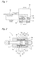
- Fig. 1 illustrates a semi-active damper control system (hereinafter referred to as a control system as necessary) including a uniflow type hydraulic shock absorber 1 according to the first embodiment.
- the control system includes the hydraulic shock absorber 1 (a hydraulic shock absorber) disposed between a bogie 31 and a vehicle body 32 (i.e. between members) relatively displaceable in a lateral direction of a railway vehicle (a horizontal direction in Fig.
- an acceleration sensor 33 (a vibration detection unit) mounted on the vehicle body 32 (one of the members), and a controller 34 that performs semi-active control (for example, Skyhook control) on the hydraulic shock absorber 1 according to a detection value detected by the acceleration sensor 33, i.e., a vibration transmitted to the vehicle body 32.
- the vehicle body 32 is elastically supported by air springs 35 disposed between the bogie 31 and the vehicle body 32.
- the control unit includes the vibration detection unit, and a damping force adjustment unit that will be described below.
- the hydraulic shock absorber 1 has a double tube structure including an outer tube 3 disposed outside a cylinder 2.
- a reservoir 4 is defined between the cylinder 2 and the outer tube 3.
- a piston 5 is slidably and fittedly inserted in the cylinder 2, and the interior of the cylinder 2 is divided by the piston 5 into two cylinder chambers, a first cylinder chamber 2A and a second cylinder chamber 2B.
- the piston 5 is coupled to one end of a piston rod 6 (a right-side end in Fig. 2 ).
- the piston rod 6 penetrates through the first cylinder chamber 2A, and is inserted through a rod guide 7 attached to ends of the cylinder 2 and the outer tube 3 on opening sides (the left side in Fig. 2 ). Then, an opposite end of the piston rod 6 (a left-side end in Fig. 2 ) extends out of the cylinder 2.
- a base valve 8, which separates the second cylinder chamber 2B and the reservoir 4, is attached to an end of the cylinder 2 (a right-side end in Fig. 2 ) opposite from the end to which the rod guide 7 is attached.
- hydraulic fluid (hydraulic fluid) is sealingly contained in the cylinder 2, and the hydraulic fluid and gas are sealingly contained in the reservoir 4.
- the piston 5 includes a flow passage 9 that establishes communication between the first cylinder chamber 2A and the second cylinder chamber 2B, and a check valve 10 that allows a flow of the hydraulic fluid (hydraulic oil) in the flow passage 9 from the second cylinder chamber 2B to the first cylinder chamber A while prohibiting a flow of the hydraulic fluid in the flow passage 9 from the first cylinder chamber 2A to the second cylinder chamber 2B.
- the base valve 8 includes a flow passage 11 that establishes communication between the second cylinder chamber 2B and the reservoir 4, and a check valve 12 that allows a flow of the hydraulic fluid in the flow passage 11 from the reservoir 4 to the second cylinder chamber 2B while prohibiting a flow of the hydraulic fluid in the flow passage 11 from the second cylinder chamber 2B to the reservoir 4.
- the shock absorber 1 includes a passage member 13 formed into a cylindrical shape and fitted to an outer circumference of the cylinder 2. Tow annular grooves (unlabeled) are formed on an inner circumferential surface 13b of the passage member 13 so as to extend circumferentially and be spaced apart from each other axially (in the horizontal direction in Fig. 2 ). As a result, an annular flow passage 15 is defined between the annular groove on the left side in Fig. 2 and an outer circumferential surface 2a of the cylinder 2, and an annular flow passage 18 is defined between the annular groove on the right side in Fig. 2 and the outer circumferential surface 2a of the cylinder 2.
- the annular flow passage 15 is in communication with the first cylinder chamber 2A via a flow passage 16 formed on a sidewall of the cylinder 2.
- the annular flow passage 18 is in communication with the second cylinder chamber 2B via a flow passage 19 formed on the sidewall of the cylinder 2.
- the damping force generation apparatus 25 has the basic structure of the damping force generation apparatus according to the conventional technique (for example, Japanese Patent Public Disclosure No. H09-264364 (Patent Document 1)) including an extension-side damping force generation mechanism 26 and a compression-side damping force generation mechanism 27 that will be described below.
- Patent Document 1 Japanese Patent Public Disclosure No. H09-264364
- the known basic structure of the damping force generation apparatus 25 will not be specifically described herein.
- Fig. 3 illustrates an overview of a hydraulic circuit for facilitating better understanding of the damping force generation apparatus 25 in the uniflow type hydraulic shock absorber 1 according to the first embodiment.
- the damping force generation apparatus 25 includes a flow passage 37 that connects the first cylinder chamber 2A and the second cylinder chamber 2B of the hydraulic shock absorber 1.
- a filter 38, the extension-side damping force generation mechanism 26, and the compression-side damping force generation mechanism 27 are disposed in the flow passage 37 in this order from the first cylinder chamber 2A to the second cylinder chamber 2B.
- a proportional solenoid valve is employed as each of the extension-side damping force generation mechanism 26 and the compression-side damping force generation mechanism 27.
- the extension-side damping force generation mechanism 26 and the compression-side damping force generation mechanism 27 will be referred to as the proportional solenoid valve 26 and the proportional solenoid valve 27 as necessary.
- the extension-side damping force generation mechanism 26 and the compression-side damping force generation mechanism 27 are not limited to a proportional solenoid valve.
- a device configured to be driven by an actuator to generate a damping force, such as a solenoid on/off valve may be employed as each of the extension-side damping force generation mechanism 26 and the compression-side damping force generation mechanism 27.
- the damping force generation apparatus 25 includes a flow passage 40 that connects a branch portion 39, which is provided between the proportional solenoid valve 26 and the proportional solenoid valve 27 in the flow passage 37, and the second cylinder chamber 2B.
- a filter 41 and a second open/close valve 42 are disposed in the flow passage 40 in this order from the branch portion 39 to the second cylinder chamber 2B.
- the damping force generation apparatus 25 includes a bypass passage 43 that bypasses the proportional solenoid valve 26 and the proportional solenoid valve 27.
- a passive damping force generation mechanism 46 (hereinafter referred to as the passive valve 46 as necessary) and a first open/close valve 47 (the valve mechanism) are disposed in the bypass passage 43 in this order from a branch portion 44 to a branch portion 45, which branch the flow passage 37.
- the second open/close valve 42 is embodied by a normally closed electromagnetic solenoid valve.
- Fig. 3 shows an opened state of the second open/close valve 42 when it is powered on or energized.
- the first open/close valve 47 is embodied by a normally opened electromagnetic solenoid valve.
- Fig. 3 shows a closed state of the first open/close valve 47 when it is powered on or energized.
- the passive valve 46 is embodied by a relief valve that generates a damping force of a passive characteristic according to a flow of the hydraulic fluid, i.e., a movement speed of the piston 5.
- the above-described controller 34 includes a damping force control unit (the damping force adjustment unit) that adjusts control current values to be supplied to the electromagnetic solenoids of the proportional solenoid valve 26 and the proportional solenoid valve 27 according to an acceleration signal detected by the acceleration sensor 33 to adjust damping forces generated by the extension-side damping force generation mechanism 26 and the compression-side damping force generation mechanism 27 between the hard side and the soft side.
- a damping force control unit the damping force adjustment unit
- Fig. 3 illustrates how the control system operates when a control mode of the damping force generation apparatus 25 by the controller 34 (hereinafter referred to as the control mode) is a semi-active control mode.
- the control mode a control mode of the damping force generation apparatus 25 by the controller 34
- the semi-active control mode the first open/close valve 47 (the valve mechanism) is powered on and is set in a closed state, while the second open/close valve 42 (the valve mechanism) is powered on and is set in an opened state.
- the proportional solenoid valve 26 (the extension-side damping force generation mechanism) is subjected to on-road control while the proportional solenoid valve 27 (the compression-side damping force generation mechanism) is subjected to off-road control (fixed at the soft side).
- the hydraulic fluid in the first cylinder chamber 2A is introduced into the flow passage 37, and is then introduced into the flow passage 40 via the filter 38 and the proportional solenoid valve 26. Then, the hydraulic fluid introduced into the flow passage 40 is supplied into the second cylinder chamber 2B via the filter 41 and the second open/close valve 42.
- the transmission of the hydraulic fluid via the proportional solenoid valve 26 causes an extension-side damping force to be generated according to a control current supplied from the controller 34 to the electromagnetic solenoid of the proportional solenoid valve 26.
- the hydraulic fluid for compensation for a volume of the piston rod 6 is supplied from the reservoir 4 into the second cylinder chamber 2B.
- the proportional solenoid valve 27 is subjected to the on-road control while the proportional solenoid valve 26 is subjected to the off-road control (fixed at the soft side).
- the hydraulic fluid in the second cylinder chamber 2B is introduced into the first cylinder chamber 2A via the flow passage 9 and the check valve 10.
- the hydraulic fluid for compensation for the volume of the piston rod 6 is introduced into the flow passage 40, and is then introduced into the flow passage 37 via the second open/close valve 42 and the filter 41.
- the hydraulic fluid introduced into the flow passage 37 is supplied into the reservoir 4 via the proportional solenoid valve 27.
- the transmission of the hydraulic fluid via the proportional solenoid valve 27 causes a compression-side damping force to be generated according to a control current supplied from the controller 34 to the electromagnetic solenoid of the proportional solenoid valve 27.
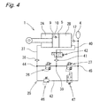
- the controller 34 determines that abnormality occurs in the control system, and switches the control mode from the semi-active control mode to the failure mode. As illustrated in Figs. 4 and 6 , in the failure mode, the controller 34 powers off the proportional solenoid valve 26 (the extension-side damping force generation mechanism) and the proportional solenoid valve 27 (the compression-side damping force generation mechanism) to fix them at the hard side, and powers off the first open/close valve 47 to open it.
- the controller 34 can determine that a vibration of the vehicle body 32 exceeds the predetermined threshold value, i.e., that abnormality occurs in the control system, based on a known method such as a method of comparing an acceleration of the vehicle body 32 calculated based on a detection value of the acceleration sensor 33 with a threshold value, a method of comparing an integral value of an acceleration per unit time with respect to the vehicle body 32 with a threshold value, a method of comparing vehicle information (vehicle speed information and positional information) with previous data, a method of calculating a ride comfort level per distance or time to compare it with a threshold value, a method of comparing a pressure value of each of the proportional solenoid valves 26 and 27 detected by a pressure sensor with a threshold value, or a combination of these methods.
- a known method such as a method of comparing an acceleration of the vehicle body 32 calculated based on a detection value of the acceleration sensor 33 with a threshold value, a method of comparing an integral value of an acceleration per unit time with
- the hydraulic fluid in the first cylinder chamber 2A is introduced into the flow passage 37, and is then introduced into the bypass passage 43 via the filter 38. Then, the hydraulic fluid introduced into the bypass passage 43 is supplied into the second cylinder chamber 2B via the passive valve 46, the first open/close valve 47, and the flow passage 37. At this time, the transmission of the hydraulic fluid via the passive valve 46 causes a damping force of the passive characteristic to be generated according to the flow of the hydraulic fluid, i.e., the movement speed of the piston 5.
- the hydraulic fluid for compensation for the volume of the piston rod 6 is supplied from the reservoir 4 into the second cylinder chamber 2B.
- the hydraulic fluid in the second cylinder chamber 2B is introduced into the first cylinder chamber 2A via the flow passage 9 and the check valve 10. Then, the hydraulic fluid for compensation for the volume of the piston rod 6 is introduced from the first cylinder chamber 2A into the flow passage 37, and is then introduced into the bypass passage 43 via the filter 38. Then, the hydraulic fluid introduced into the bypass passage 43 is transmitted via the passive valve 46 and the first open/close valve 47, and is further transmitted via the flow passage 37 to be supplied into the reservoir 4. At this time, the transmission of the hydraulic fluid via the passive valve 46 causes a damping force of the passive characteristic to be generated according to the flow of the hydraulic fluid.
- the conventional technique cannot generate a desired damping force larger than the soft side even if an instruction for a current corresponding to a higher damping force than the soft side is issued, because the proportional solenoid valve 26 is stuck at the soft side so that the hydraulic fluid flows via the stuck proportional solenoid valve 26 and the second open/close valve 42.
- the vehicle body 32 vibrates largely, thereby reducing the ride comfort and running stability of the vehicle.
- the controller 34 switches the control mode from the semi-active control mode to the failure mode, i.e., the proportional solenoid valve 26 (the extension-side damping force generation mechanism) and the proportional solenoid valve 27 (the compression-side damping force generation mechanism) are set in states powered off and fixed at the hard side. Then, if a larger vibration than a preset vibration continues after the failure mode is maintained for a predetermined certain time period, the controller 34 determines that the proportional solenoid valve 26 or the proportional solenoid valve 27 is stuck at the soft side, and switches the control mode from the failure mode to the passive mode.
- the proportional solenoid valve 26 the extension-side damping force generation mechanism
- the proportional solenoid valve 27 the compression-side damping force generation mechanism
- Fig. 5 illustrates how the control system operates when the control mode is the passive mode.
- the controller 34 powers off the second open/close valve 42 to close it.
- the first open/close valve 47 is held in the opened state by being powered off, and the proportional solenoid valve 26 (the extension-side damping force generation mechanism) and the proportional solenoid valve 27 (the compression-side damping force generation mechanism) remain fixed at the hard side by being powered off.
- the hydraulic fluid in the first cylinder chamber 2A is introduced into the flow passage 37, and is introduced into the bypass passage 43 via the filter 38. Then, the hydraulic fluid introduced into the bypass passage 43 is transmitted via the passive valve 46 and the first open/close valve 47, and is further transmitted via the flow passage 37 to be supplied into the second cylinder chamber 2B. At this time, the transmission of the hydraulic fluid via the passive valve 46 causes a damping force of the passive characteristic to be generated according to the flow of the hydraulic fluid, i.e., the moving speed of the piston 5. The hydraulic fluid for compensation for the volume of the piston rod 6 is supplied from the reservoir 4 into the second cylinder chamber 2B.
- the hydraulic fluid in the second cylinder chamber 2B is introduced into the first cylinder chamber 2A via the flow passage 9 and the check valve 10. Then, the hydraulic fluid for compensation for the volume of the piston rod 6 is introduced from the first cylinder chamber 2A into the flow passage 37, and is then introduced into the bypass passage 43 via the filter 38. Then, the hydraulic fluid introduced into the bypass passage 43 is transmitted via the passive valve 46 and the first open/close valve 47, and is further transmitted via the flow passage 37 to be supplied into the reservoir 4. At this time, the transmission of the hydraulic fluid via the passive valve 46 causes a damping force of the passive characteristic to be generated according to the flow of the hydraulic fluid.
- the hydraulic shock absorber (the hydraulic shock absorber) cannot generate a damping force even if the control mode is switched from the semi-active control mode to the failure mode. As a result, the vehicle body 32 vibrates largely, thereby reducing the ride comfort and running stability of the vehicle.
- the controller 34 determines that the proportional solenoid valve 26 or the proportional solenoid valve 27 is stuck at the soft side, and switches the control mode from the failure mode to the passive mode.
- the damping force generation apparatus 25 is configured in such a manner that the hydraulic fluid sent from the first cylinder chamber 2A by a movement of the piston 5 is not introduced into the semi-active control system, i.e., is introduced into the bypass passage 43 to be transmitted via the passive valve 46 (the passive damping force generation mechanism) in the passive mode, and therefore can generate a damping force of the passive characteristic according to the flow of the hydraulic fluid, i.e., the movement speed of the piston 5.
- the uniflow type hydraulic shock absorber 1 (the hydraulic shock absorber) can function as a normal passive damper, i.e., can generate a damping force of the passive characteristic.
- the proportional solenoid valve 26 (the extension-side damping force generation mechanism) or the proportional solenoid valve 27 (the compression-side damping force generation mechanism) may be a switching valve that is switched between two positions of the hard characteristic and the soft characteristic.
- a uniflow type hydraulic shock absorber 51 according to the second embodiment is formed by replacing the second open/close valve 42 (refer to Figs. 3 , 4 , and 5 ) disposed in the flow passage 40 of the semi-active damper control system in the uniflow type hydraulic shock absorber 1 according to the first embodiment with a pilot type shutoff valve 52.
- the pilot type shutoff valve 52 is switched from the opened state to the closed state when the pressure in the flow passage 37 (a pilot flow passage 54) increases to reach a predetermined pilot pressure.
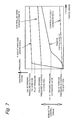
- the pilot pressure of the pilot type shutoff valve 52 is set so as to be lower than valve opening pressures (super hard valve opening pressures) of the proportional solenoid valve 26 (the extension-side damping force generation mechanism) and the proportional solenoid valve 27 (the compression-side damping force generation mechanism) that generate hard damping forces in the failure mode, and higher than valve opening pressures (hard-side valve opening pressures) of the proportional solenoid valves 26 and 27 that generate hard-side damping forces in the semi-active control mode.
- a valve opening pressure (a damping force) of the passive valve 46 (the passive damping force generation mechanism) is set so as to be higher than valve opening pressures (soft-side valve opening pressures, damping forces) of the proportional solenoid valves 26 and 27 that generate soft-side damping forces in the semi-active control mode, and lower than the valve opening pressures (hard-side valve opening pressures, damping forces) of the proportional solenoid valves 26 and 27 that generate the hard-side damping forces in the semi-active control mode.
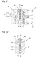
- Fig. 9 is a cross-sectional view of a valve block 53 of the damping force generation apparatus 25, which is taken along a plane including the proportional solenoid valve 26 (the extension-side damping force generation mechanism), the proportional solenoid valve 27 (the compression-side damping force generation mechanism), and the pilot type shutoff valve 52.
- the pilot type shutoff valve 52 includes a cylinder 55 having one end (a lower end in Fig. 9 ) connected to the flow passage 37 via a flow passage 54 (a pilot flow passage) and an opposite end opened to the outside of the valve block 53, a screw 56 fixed (screwed) in an opening of the cylinder 55, and a valve body 57 contained in the cylinder 55.
- the valve body 57 includes a large-diameter portion 57A slidably fitted in the cylinder 55, and a small-diameter portion 57B slidably fitted in an axial hole 56A of the screw 56.
- a circumferentially extending annular groove (unlabeled) is formed around the large-diameter portion 57A, by which an annular flow passage 58 is defined between the annular groove and the cylinder 55.
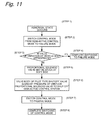
- Fig. 11 illustrates a control flow of the uniflow type hydraulic shock absorber 51 according to the second embodiment.
- the first open/close valve 47 (the valve mechanism) is powered on and is set in the closed state
- the pilot type shutoff valve 52 (the valve mechanism) is set in the opened state because the supplied pressure does not reach the pilot pressure. Therefore, during the extension stroke, a damping force adjusted by the proportional solenoid valve 26 (the extension-side damping force generation mechanism) is generated according to the control current supplied from the controller 34.
- a damping force adjusted by the proportional solenoid valve 27 (the compression-side damping force generation mechanism) is generated according to the control current supplied from the controller 34.
- the controller 34 determines that abnormality occurs in the control system (step 1 in Fig. 11 ), and switches the control mode from the semi-active control mode to the failure mode (step 2 in Fig. 11 ). In the failure mode, the controller 34 powers off the proportional solenoid valve 26 (the extension-side damping force generation mechanism) and the proportional solenoid valve 27 (the compression-side damping force generation mechanism) to fix them at the hard side.
- the controller 34 determines whether the vibration of the vehicle body 32 is appropriate (step 3 in Fig. 11 ). If the controller 34 determines at this time that the vibration of the vehicle body 32 is appropriate (YES in step 3 in Fig. 11 ), the controller 34 completes switching to the failure mode (step 4 in Fig. 11 ). On the other hand, if the controller 34 determines that the vibration of the vehicle body 32 is not appropriate (NO in step 3 in Fig.
- the controller 34 determines that the proportional solenoid valve 26 or the proportional solenoid valve 27 is stuck at the soft side, when the state having abnormality is maintained for the predetermined certain time period with the control mode switched to the failure mode, i.e., the proportional solenoid valve 26 and the proportional solenoid valve 27 fixed at the hard side (step 5 in Fig. 11 ).
- the controller 34 switches the control mode from the failure mode to the passive mode (step 7 in Fig. 11 ).
- the first open/close valve 47 (the valve mechanism) is powered off and is opened, and the hydraulic fluid starts to be introduced into the bypass passage 43.
- the transmission of the hydraulic fluid flowing in the bypass passage 43 via the passive valve 46 causes a damping force of the passive characteristic to be generated according to the flow of the hydraulic fluid, i.e., the movement speed of the piston 5.
- switching of the control mode is completed (step 8 in Fig. 11 ).
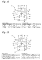
- the first operation state is an operation state of the control system when the control mode is the semi-active control mode.
- Fig. 12 illustrates the control system in the first operation state. As illustrated in Fig. 12 , in the first operation state, the pilot type shutoff valve 52 (the valve mechanism) is in the opened state. Further, the first open/close valve 47 (the valve mechanism) is powered on and is in the closed state, which shuts off a flow of the hydraulic fluid into the bypass passage 43.
- the proportional solenoid valve 26 (the extension-side damping force generation mechanism) is subjected to the on-road control while the proportional solenoid valve 27 (the compression-side damping force generation mechanism) is subjected to the off-road control (fixed at the soft side).
- the hydraulic fluid in the first cylinder chamber 2A is introduced into the flow passage 37, and is then introduced into the flow passage 40 via the filter 38 and the proportional solenoid valve 26. Then, the hydraulic fluid introduced into the flow passage 40 is supplied into the second cylinder chamber 2B via the filter 41 and the pilot type shutoff valve 52.
- the transmission of the hydraulic fluid via the proportional solenoid valve 26 causes an extension-side damping force to be generated according to the control current supplied from the controller 34 to the electromagnetic solenoid of the proportional solenoid valve 26.
- the hydraulic fluid for compensation for the volume of the piston rod 6 is supplied from the reservoir 4 to the second cylinder chamber 2B.
- the proportional solenoid valve 27 is subjected to the on-road control while the proportional solenoid valve 26 is subjected to the off-road control (fixed at the soft side).
- the hydraulic fluid in the second cylinder chamber 2B is introduced into the first cylinder chamber 2A via the flow passage 9 and the check vale 10.
- the hydraulic fluid for compensation for the volume of the piston rod 6 is introduced into the flow passage 40, and is then introduced into the flow passage 37 via the pilot type shutoff valve 52 and the filter 41.
- the hydraulic fluid introduced into the flow passage 37 is supplied into the reservoir 4 via the proportional solenoid valve 27.
- the transmission of the hydraulic fluid via the proportional solenoid valve 27 causes a compression-side damping force to be generated according to the control current supplied form the controller 34 to the electromagnetic solenoid of the proportional solenoid valve 27.
- the second operation state is an operation mode of the control system when the control mode is the failure mode.
- Fig. 13 illustrates the control system in the second operation mode.
- the proportional solenoid valve 26 the extension-side damping force generation mechanism
- the proportional solenoid valve 27 the compression-side damping force generation mechanism
- the second operation state is the operation state in step 4 in the control flow illustrated in Fig. 11 .
- the hydraulic fluid in the first cylinder chamber 2A is introduced into the flow passage 37, and is then introduced into the bypass passage 43 via the filter 38. Then, the hydraulic fluid introduced into the bypass passage 43 is transmitted via the passive valve 46 and the first open/close valve 47, and is further transmitting via the flow passage 37 to be supplied into the second cylinder chamber 2B. At this time, the transmission of the hydraulic fluid via the passive valve 46 causes a damping force of the passive characteristic to be generated according to the flow of the hydraulic fluid, i.e., the movement speed of the piston 5.
- the hydraulic fluid for compensation for the volume of the piston rod 6 is supplied from the reservoir 4 into the second cylinder chamber 2B.
- the hydraulic fluid in the second cylinder chamber 2B is introduced into the first cylinder chamber 2A via the flow passage 9 and the check valve 10. Then, the hydraulic fluid for compensation for the volume of the piston rod 6 is introduced from the first cylinder chamber 2A into the flow passage 37, and is then introduced into the bypass passage 43 via the filter 38. Then, the hydraulic fluid introduced into the bypass passage 43 is transmitted via the passive valve 46 and the first open/close valve 47, and is then supplied into the reservoir 4 via the flow passage 43. At this time, the transmission of the hydraulic fluid via the passive valve 46 causes a damping force of the passive characteristic to be generated according to the flow of the hydraulic fluid.
- a third operation state is such a state that the proportional solenoid valve 26 (the extension-side damping force generation mechanism) is stuck at the soft side in the first operation state illustrated in Fig. 12 .
- the pilot type shutoff valve 52 is set in the opened state because the pressure in the flow passage 54 in communication with the first cylinder chamber 2A does not reach the pilot pressure.
- the damping force generation apparatus 25 can perform the semi-active control, i.e., can generate a damping force according to the control current of the controller 34.
- the third operation state is the operation state in step 1 in the control flow illustrated in Fig. 11 .
- a fourth operation state is such a state that the proportional solenoid valve 26 (the extension-side damping force generation mechanism) is stuck at the soft side in the second operation state illustrated in Fig. 13 .
- the damping force generation apparatus 25 can perform the semi-active control by a damping force generated by the proportional solenoid valve 27.
- the hydraulic fluid is not introduced into the bypass passage 43, and is released toward the proportional solenoid valve 26 stuck at the soft side corresponding a further lower valve opening pressure (a damping force).
- the damping force generation apparatus 25 cannot generate a damping force during the extension stroke, whereby the vehicle vibrates largely.
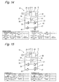
- the fifth operation state is an operation state when a vibration of the vehicle exceeds a certain degree in the third operation state, i.e., the movement speed of the piston 5 exceeds a certain speed.
- the proportional solenoid valve 26 (the extension-side damping force generation mechanism) is stuck at the soft side (powered off and a hard instruction).
- the proportional solenoid valve 27 (the compression-side damping force generation mechanism) is powered off and is fixed at the hard side.
- the first open/close valve 47 (the valve mechanism) is powered on and is set in the closed state, thereby shutting off the flow of the hydraulic fluid to the bypass passage 43. Further, when the pressure in the flow passage 54 in communication with the first cylinder chamber 2A reaches the pilot pressure, the pilot type shutoff valve 52 is actuated to be closed.
- the hydraulic fluid is transmitted via the proportional solenoid valve 27 fixed at the hard side after being transmitted via the proportional solenoid valve 26. Therefore, the control system has a release characteristic fixed at the hard side. As a result, the hydraulic shock absorber 51 is set in a locked state, whereby the vehicle body 32 vibrates largely. Further, the ride comfort of the vehicle is deteriorated to provide a rattling uncomfortable feeling.
- the controller 34 determines that the proportional solenoid valve 26 or the proportional solenoid valve 27 is stuck at the soft side when the fifth operation state (the state having abnormality) is maintained for a predetermined certain time period, and switches the operation state from the fifth operation state to the sixth operation state.
- the proportional solenoid valve 26 (the extension-side damping force generation mechanism) is stuck at the soft side (powered off and a hard instruction).
- the proportional solenoid valve 27 (the compression-side damping force generation mechanism) is powered off and is fixed at the hard side.
- the pilot type shutoff valve 52 is provided with the pilot pressure to be set in the closed state. Further, the first open/close valve 47 is powered off and is set in the opened state.
- the hydraulic fluid in the first cylinder chamber 2A is introduced into the flow passage 37, and is then introduced into the bypass passage 43 via the filter 38. Then, the hydraulic fluid introduced in to the bypass passage 43 is transmitted via the passive valve 46 and the first open/close valve 47, and is further transmitted via the flow passage 37 to be supplied into the second cylinder chamber 2B. At this time, the transmission of the hydraulic fluid via the passive valve 46 causes a damping force of the passive characteristic to be generated according to the flow of the hydraulic fluid, i.e., the movement speed of the piston 5. The hydraulic fluid for compensation for the volume of the piston rod 6 is supplied from the reservoir 4 into the second cylinder chamber 2B.
- the hydraulic fluid in the second cylinder chamber 2B is introduced into the first cylinder chamber 2A via the flow passage 9 and the check valve 10. Then, the hydraulic fluid for compensation for the volume of the piston rod 6 is introduced from the first cylinder chamber 2A into the flow passage 37, and is then introduced into the bypass passage 43 via the filter 38. Then, the hydraulic fluid introduced into the bypass passage 43 is transmitted via the passive valve 46 and the first open/close valve 47, and is further transmitted via the flow passage 37 to be supplied into the reservoir 4. At this time the transmission of the hydraulic fluid via the passive valve 46 causes a damping force of the passive characteristic to be generated according to the flow of the hydraulic fluid.
- the pilot type shutoff valve 52 (the valve mechanism) is used instead of the second open/close valve 42 (the electromagnetic solenoid valve) in the first embodiment, whereby it is possible to reduce manufacturing cost and reduce a load on the controller 34 compared to the first embodiment.
- the third embodiment is such an embodiment that the configuration of the semi-active damper control system in the uniflow type hydraulic shock absorber 51 according to the second embodiment is applied to a biflow type hydraulic shock absorber (the hydraulic shock absorber) 61.
- Fig. 16 illustrates the control system when the control mode is the semi-active control mode according to the third embodiment.
- a pilot type shutoff valve 52A and a pilot type shutoff valve 52B are set in the opened states.
- the first open/close valve 47 (the valve mechanism) is powered on and is set in the closed state, thereby shutting off the flow of the hydraulic fluid to the bypass passage 43.
- the proportional solenoid valve 26 (the extension-side damping force generation mechanism) is subjected to the on-road control while the proportional solenoid valve 27 (the compression-side damping force generation mechanism) is subjected to the off-road control (fixed at the soft side).
- the hydraulic fluid in the first cylinder chamber 2A is introduced into the second cylinder chamber 2B via the filter 38, the proportional solenoid valve 26, the filter 41, the pilot type shutoff valve 52B, and the pilot type shutoff valve 52A.
- the transmission of the hydraulic fluid via the proportional solenoid valve 26 causes an extension-side damping force to be generated according to the control current supplied from the controller 34 to the electromagnetic solenoid of the proportional solenoid valve 26.
- the proportional solenoid valve 27 is subjected to the on-road control while the proportional solenoid valve 26 is subjected to the off-road control (fixed at the soft side).
- the hydraulic fluid in the second cylinder chamber 2B is introduced into the first cylinder chamber 2A via the proportional solenoid valve 27, the filter 41, the pilot type shutoff valve 52B, and the pilot type shutoff valve 52A.
- the transmission of the hydraulic fluid via the proportional solenoid valve 27 causes a compression-side damping force to be generated according to the control current supplied from the controller 34 to the electromagnetic solenoid of the proportional solenoid valve 27.
- Fig. 17 illustrates the control system when the control mode is the failure mode.
- the proportional solenoid valve 26 the extension-side damping force generation mechanism
- the proportional solenoid valve 27 the compression-side damping force generation mechanism
- the pilot type shutoff valve 52A and the pilot type shutoff valve 52B are set in the opened states.
- the hydraulic fluid in the first cylinder chamber 2A is introduced into the second cylinder chamber 2B via the filter 38, a passive valve 46A (the passive damping force mechanism), the first open/close valve 47 (the valve mechanism), the filter 41, the pilot type shutoff valve 52B, and the pilot type shutoff valve 52A.
- the transmission of the hydraulic fluid via the passive valve 46A causes a damping force of the passive characteristic to be generated according to the flow of the hydraulic fluid, i.e., the movement speed of the piston 5.
- the control system may be configured in such a manner that the downstream side of the first open/close valve 47 is connected directly to the reservoir 4 without the filter 41, the pilot type shutoff valve 52B, and the pilot type shutoff valve 52A located therebetween.
- the hydraulic fluid in the second cylinder chamber 2B is introduced into the first cylinder chamber 2A via the passive valve 46A, the first open/close valve 47 (the valve mechanism), the filter 41, the pilot type shutoff valve 52B, and the pilot type shutoff valve 52A.
- the transmission of the hydraulic fluid via the passive valve 46A causes a damping force of the passive characteristic to be generated according to the flow of the hydraulic fluid.
- Fig. 18 illustrates the control system in the passive mode with the proportional solenoid valve 27 (the extension-side damping force generation mechanism) stuck at the soft side (powered off and a hard instruction).
- the valve opening pressure (super hard) of the proportional solenoid valve 26, which is not stuck at the soft side and is fixed at the hard side, is higher than the pilot pressure of the pilot type shutoff valve 52A, whereby the pilot type shutoff valve 52A is actuated and is closed.
- the pilot type shutoff valve 52A is closed, the first open/close valve 47 is powered off and is opened.
- the valve opening pressure of the passive valve 46A and the valve opening pressure (damping force) of a passive valve 46B are set to a same pressure.
- the hydraulic fluid in the first cylinder chamber 2A is introduced into the second cylinder chamber 2B via the filter 38, the passive valve 46A, and the passive valve 46B.
- the transmission of the hydraulic fluid via the passive valve 46A causes a damping force of the passive characteristic to be generated according to the flow of the hydraulic fluid, i.e., the movement speed of the piston 5.
- the hydraulic fluid in the second cylinder chamber 2B is introduced into the first cylinder chamber 2A via the passive valve 46B, the passive valve 46A, and the filter 38.
- the transmission of the hydraulic fluid via the passive valve 46B causes a damping force of the passive characteristic to be generated according to the flow of the hydraulic fluid.
- the first open/close valve 47 is embodied by a normally opened electromagnetic solenoid.
- the first open/close valve 47 may be embodied by a normally closed electromagnetic solenoid.
- a hydraulic shock absorber which is configured to be disposed between relatively displaceable members, includes a cylinder (2) sealingly containing hydraulic fluid, a piston (5) slidably fitted in the cylinder and dividing an interior of the cylinder into two chambers, a piston rod (6) having one end coupled to the piston and an opposite end extending out of the cylinder, an extension-side damping force generation mechanism (26) configured to adjust an extension-side damping force by controlling a flow of the hydraulic fluid and configured to be driven by a solenoid, a compression-side damping force generation mechanism (27) configured to adjust a compression-side damping force by controlling a flow of the hydraulic fluid and configured to be driven by a solenoid, and a control unit.
- the control unit includes a vibration detection unit (33) configured to detect a vibration transmitted to one of the members, and a damping force adjustment unit (34) configured to adjust control current values of the solenoids according to a detection value of the vibration detection unit to adjust damping forces generated by the extension-side damping force generation mechanism and the compression-side damping force generation mechanism between a hard side and a soft side.
- a vibration detection unit (33) configured to detect a vibration transmitted to one of the members
- a damping force adjustment unit configured to adjust control current values of the solenoids according to a detection value of the vibration detection unit to adjust damping forces generated by the extension-side damping force generation mechanism and the compression-side damping force generation mechanism between a hard side and a soft side.
- the above-described hydraulic shock absorber can further include a bypass passage (43) bypassing the extension-side damping force generation mechanism and the compression-side damping force generation mechanism, a passive damping force generation mechanism (46; 46A, 46B) disposed in the bypass passage and configured to generate a damping force of a passive characteristic according to a flow of the hydraulic fluid, and a valve mechanism (42, 47; 52; 52A, 52B) configured to be switched in such a manner that the damping force is generated by the passive damping force generation mechanism when the control unit determines that the extension-side damping force generation mechanism or the compression-side damping force generation mechanism is stuck at the soft side.
- the valve mechanism can include a pilot type shutoff valve (52; 52A, 52B) configured to shut off a flow of the hydraulic fluid through the extension-side damping force generation mechanism and the compression-side damping force generation mechanism by a pressure in the cylinder and maintain a shutoff state after shutting off this flow.
- a pilot type shutoff valve 52; 52A, 52B
- valve mechanism can include an open/close valve mechanism (47) disposed on a downstream side of the passive damping force generation mechanism (46; 46A, 46B).
- valve mechanism can include an open/close valve mechanism (52; 52A, 52B) disposed on a downstream side of the extension-side damping force generation mechanism (26) and the compression-side damping force generation mechanism (27).
- the valve mechanism can include first and second pilot type shutoff valves (52A, 52B) disposed on the downstream side of the extension-side damping force generation mechanism (26) and the compression-side damping force generation mechanism (27).
- the first pilot type shutoff valve (52A) can be configured to be opened and closed by a hydraulic pressure in one (2A) of the chambers in the cylinder
- the second pilot type shutoff valve (52B) can be configured to be opened and closed by a hydraulic pressure in the other (2B) of the chambers in the cylinder.
- the passive damping force generation mechanism can include a first passive damping force generation mechanism (46A) and a second passive damping force generation mechanism (46B).
- the valve mechanism can include the open/close valve mechanism (47) connected to a downstream side of the first passive damping force generation mechanism (46A) and the second passive damping force generation mechanism (46B).
- the passive damping force generation mechanism can include the first passive damping force generation mechanism (46A) and the second passive damping force generation mechanism (46B).
- the valve mechanism can include the open/close valve mechanism (47) disposed in a flow passage that connects a branch point between the first passive damping force generation mechanism (46A) and the second passive damping force generation mechanism (46B) with a branch point between the extension-side damping force generation mechanism (26) and the compression-side damping force generation mechanism (27), and the first and second pilot type shutoff valves (52A, 52B) disposed in a flow passage that connects the branch point between the extension-side damping force generation mechanism (26) and the compression-side damping force generation mechanism (27) with the two chambers in the cylinder.
- the above-described hydraulic shock absorber can be a biflow type hydraulic shock absorber.
- the above-described can be a uniflow type hydraulic shock absorber.
- the piston (5) can include a check valve (10) that allows a unidirectional flow of the hydraulic fluid between the two chambers (2A, 2B) in the cylinder (2).
Landscapes
- Engineering & Computer Science (AREA)
- Mechanical Engineering (AREA)
- General Engineering & Computer Science (AREA)
- Fluid-Damping Devices (AREA)
- Vehicle Body Suspensions (AREA)
- Vibration Prevention Devices (AREA)
- Fluid-Pressure Circuits (AREA)
Abstract
Description
- The present invention relates to a hydraulic shock absorber.
- Conventionally, there has been known a damping force adjustable hydraulic shock absorber including an extension-side damping force generation mechanism and a compression-side damping force generation mechanism configured to be driven by solenoids (for example, refer to Japanese Patent Public Disclosure No.
H09-264364 - For example, if an electromagnetic solenoid valve of the extension-side damping force generation mechanism (hereinafter referred to as an extension-side solenoid valve) is stuck at a soft side (hereinafter referred to as "stuck at the soft side"), a semi-active damper control system of a railway vehicle including a uniflow type hydraulic shock absorber capable of adjusting a damping force cannot generate a desired damping force when the vehicle is in a state requiring a hard characteristic. As a result, a vehicle body largely vibrates, thereby reducing a ride comfort and running stability of the vehicle.
- The present invention has been contrived in consideration of the above-described circumstance, and an object thereof is to provide a hydraulic shock absorber capable of detecting that a damping force generation mechanism is stuck at the soft side.
- To achieve the above-described object, according to an aspect of the present invention, a hydraulic shock absorber, which is configured to be disposed between relatively displaceable members, includes a cylinder sealingly containing hydraulic fluid, a piston slidably fitted in the cylinder and dividing an interior of the cylinder into two chambers, a piston rod having one end coupled to the piston and an opposite end extending out of the cylinder, an extension-side damping force generation mechanism configured to adjust an extension-side damping force by controlling a flow of the hydraulic fluid and configured to be driven by a solenoid, a compression-side damping force generation mechanism configured to adjust a compression-side damping force by controlling a flow of the hydraulic fluid and configured to be driven by a solenoid, and a control unit. The control unit includes a vibration detection unit configured to detect a vibration transmitted to one of the members, and a damping force adjustment unit configured to adjust a control current value of the solenoid according to a detection value of the vibration detection unit to adjust damping forces generated by the extension-side damping force generation mechanism and the compression-side damping force generation mechanism between a hard side and a soft side. Upon determining that the detection value of the vibration detection unit remains larger than a predetermined value for a certain time period with the extension-side damping force generation mechanism and the compression-side damping force generation mechanism set to the hard side, the control unit determines that the extension-side damping force generation mechanism or the compression-side damping force generation mechanism is stuck at the soft side.
-
Fig. 1 illustrates a semi-active damper control system including a uniflow type hydraulic shock absorber (a hydraulic shock absorber) according to a first embodiment. -
Fig. 2 is a cross-sectional view illustrating the uniflow type hydraulic shock absorber according to the first embodiment taken along an axial plane of the hydraulic shock absorber. -
Fig. 3 is a diagram for facilitating better understanding of the first embodiment, and illustrates how a system operates when a control mode is a semi-active control mode. -
Fig. 4 is a diagram for facilitating better understanding of the first embodiment, and illustrates how the system operates when the control mode is a failure mode. -
Fig. 5 is a diagram for facilitating better understanding of the first embodiment, and illustrates how the system operates when the control mode is a passive mode. -
Fig. 6 is a table for facilitating better understanding of the first embodiment, and is a table that indicates how the system operates in each control mode. -
Fig. 7 is a graph for facilitating better understanding of a second embodiment, and is a graph for comparing damping force lines of respective damping force generation mechanisms and valve opening pressures (actuation pressures) of the respective damping force generation mechanisms. -
Fig. 8 is a diagram for facilitating better understanding of the second embodiment, and illustrates how the system operates when the control mode is the semi-active control mode. -
Fig. 9 is a diagram for facilitating better understanding of the second embodiment, and is a cross-sectional view of a valve block taken along a plane including an extension-side damping force generation mechanism, a compression-side damping force generation mechanism, and a pilot type shutoff valve. -
Fig. 10 is a diagram for facilitating better understanding of the second embodiment, and an axial cross-sectional view illustrating a pilot type shutoff valve in an actuated state in which a pilot pressure is supplied. -
Fig. 11 illustrates a control flow according to the second embodiment. -
Fig. 12 is a diagram for facilitating better understanding of the second embodiment, and illustrates the control system in a first operation state. -
Fig. 13 is a diagram for facilitating better understanding of the second embodiment, and illustrates the control system in a second operation state. -
Fig. 14 is a diagram for facilitating better understanding of the second embodiment, and illustrates the control system in a fifth operation state. -
Fig. 15 is a diagram for facilitating better understanding of the second embodiment, and illustrates the control system in a sixth operation state. -
Fig. 16 is a diagram for facilitating better understanding of a third embodiment, and illustrates how the system operates when the control mode is the semi-active control mode. -
Fig. 17 is a diagram for facilitating better understanding of the third embodiment, and illustrates how the system operates when the control mode is the failure mode. -
Fig. 18 is a diagram for facilitating better understanding of the third embodiment, and illustrates how the system operates in a passive mode when the extension-side damping force generation mechanism is stuck at the soft side. - A first embodiment of the present invention will be described with reference to the accompanying drawings. The first embodiment will be described based on an example employing a uniflow type hydraulic shock absorber (damper) designed for a semi-active damper control system of a railway vehicle as a hydraulic shock absorber. However, this example is not intended to limit the hydraulic shock absorber of the present invention thereby.
-
Fig. 1 illustrates a semi-active damper control system (hereinafter referred to as a control system as necessary) including a uniflow type hydraulic shock absorber 1 according to the first embodiment. As illustrated inFig. 1 , the control system includes the hydraulic shock absorber 1 (a hydraulic shock absorber) disposed between abogie 31 and a vehicle body 32 (i.e. between members) relatively displaceable in a lateral direction of a railway vehicle (a horizontal direction inFig. 1 ), an acceleration sensor 33 (a vibration detection unit) mounted on the vehicle body 32 (one of the members), and acontroller 34 that performs semi-active control (for example, Skyhook control) on thehydraulic shock absorber 1 according to a detection value detected by theacceleration sensor 33, i.e., a vibration transmitted to thevehicle body 32. Thevehicle body 32 is elastically supported byair springs 35 disposed between thebogie 31 and thevehicle body 32. The control unit includes the vibration detection unit, and a damping force adjustment unit that will be described below. - As illustrated in
Fig. 2 , thehydraulic shock absorber 1 has a double tube structure including anouter tube 3 disposed outside acylinder 2. Areservoir 4 is defined between thecylinder 2 and theouter tube 3. Apiston 5 is slidably and fittedly inserted in thecylinder 2, and the interior of thecylinder 2 is divided by thepiston 5 into two cylinder chambers, afirst cylinder chamber 2A and asecond cylinder chamber 2B. - The
piston 5 is coupled to one end of a piston rod 6 (a right-side end inFig. 2 ). Thepiston rod 6 penetrates through thefirst cylinder chamber 2A, and is inserted through arod guide 7 attached to ends of thecylinder 2 and theouter tube 3 on opening sides (the left side inFig. 2 ). Then, an opposite end of the piston rod 6 (a left-side end inFig. 2 ) extends out of thecylinder 2. Abase valve 8, which separates thesecond cylinder chamber 2B and thereservoir 4, is attached to an end of the cylinder 2 (a right-side end inFig. 2 ) opposite from the end to which therod guide 7 is attached. Further, hydraulic fluid (hydraulic fluid) is sealingly contained in thecylinder 2, and the hydraulic fluid and gas are sealingly contained in thereservoir 4. - The
piston 5 includes aflow passage 9 that establishes communication between thefirst cylinder chamber 2A and thesecond cylinder chamber 2B, and acheck valve 10 that allows a flow of the hydraulic fluid (hydraulic oil) in theflow passage 9 from thesecond cylinder chamber 2B to the first cylinder chamber A while prohibiting a flow of the hydraulic fluid in theflow passage 9 from thefirst cylinder chamber 2A to thesecond cylinder chamber 2B. Thebase valve 8 includes aflow passage 11 that establishes communication between thesecond cylinder chamber 2B and thereservoir 4, and acheck valve 12 that allows a flow of the hydraulic fluid in theflow passage 11 from thereservoir 4 to thesecond cylinder chamber 2B while prohibiting a flow of the hydraulic fluid in theflow passage 11 from thesecond cylinder chamber 2B to thereservoir 4. - The
shock absorber 1 includes apassage member 13 formed into a cylindrical shape and fitted to an outer circumference of thecylinder 2. Tow annular grooves (unlabeled) are formed on an innercircumferential surface 13b of thepassage member 13 so as to extend circumferentially and be spaced apart from each other axially (in the horizontal direction inFig. 2 ). As a result, anannular flow passage 15 is defined between the annular groove on the left side inFig. 2 and an outercircumferential surface 2a of thecylinder 2, and anannular flow passage 18 is defined between the annular groove on the right side inFig. 2 and the outercircumferential surface 2a of thecylinder 2. Then, theannular flow passage 15 is in communication with thefirst cylinder chamber 2A via aflow passage 16 formed on a sidewall of thecylinder 2. Theannular flow passage 18 is in communication with thesecond cylinder chamber 2B via aflow passage 19 formed on the sidewall of thecylinder 2. - As illustrated in
Fig. 2 , theouter tube 3 and thepassage member 13 are connected to each other via aconnection tube 21 in communication with theannular flow passage 15 and via aconnection tube 22 in communication with theannular flow passage 18. A dampingforce generation apparatus 25 is attached to an outercircumferential surface 3a of theouter tube 3. The dampingforce generation apparatus 25 has the basic structure of the damping force generation apparatus according to the conventional technique (for example, Japanese Patent Public Disclosure No.H09-264364 force generation mechanism 26 and a compression-side dampingforce generation mechanism 27 that will be described below. For simplification of the description of the present disclosure, the known basic structure of the dampingforce generation apparatus 25 will not be specifically described herein. -
Fig. 3 illustrates an overview of a hydraulic circuit for facilitating better understanding of the dampingforce generation apparatus 25 in the uniflow type hydraulic shock absorber 1 according to the first embodiment. As illustrating inFig. 3 , the dampingforce generation apparatus 25 includes aflow passage 37 that connects thefirst cylinder chamber 2A and thesecond cylinder chamber 2B of thehydraulic shock absorber 1. Afilter 38, the extension-side dampingforce generation mechanism 26, and the compression-side dampingforce generation mechanism 27 are disposed in theflow passage 37 in this order from thefirst cylinder chamber 2A to thesecond cylinder chamber 2B. In the first embodiment, a proportional solenoid valve is employed as each of the extension-side dampingforce generation mechanism 26 and the compression-side dampingforce generation mechanism 27. Hereinafter, the extension-side dampingforce generation mechanism 26 and the compression-side dampingforce generation mechanism 27 will be referred to as theproportional solenoid valve 26 and theproportional solenoid valve 27 as necessary. The extension-side dampingforce generation mechanism 26 and the compression-side dampingforce generation mechanism 27 are not limited to a proportional solenoid valve. A device configured to be driven by an actuator to generate a damping force, such as a solenoid on/off valve may be employed as each of the extension-side dampingforce generation mechanism 26 and the compression-side dampingforce generation mechanism 27. - The damping
force generation apparatus 25 includes aflow passage 40 that connects abranch portion 39, which is provided between theproportional solenoid valve 26 and theproportional solenoid valve 27 in theflow passage 37, and thesecond cylinder chamber 2B. Afilter 41 and a second open/close valve 42 (a valve mechanism) are disposed in theflow passage 40 in this order from thebranch portion 39 to thesecond cylinder chamber 2B. Further, the dampingforce generation apparatus 25 includes abypass passage 43 that bypasses theproportional solenoid valve 26 and theproportional solenoid valve 27. A passive damping force generation mechanism 46 (hereinafter referred to as thepassive valve 46 as necessary) and a first open/close valve 47 (the valve mechanism) are disposed in thebypass passage 43 in this order from abranch portion 44 to abranch portion 45, which branch theflow passage 37. - Further, the second open/
close valve 42 is embodied by a normally closed electromagnetic solenoid valve.Fig. 3 shows an opened state of the second open/close valve 42 when it is powered on or energized. Further, the first open/close valve 47 is embodied by a normally opened electromagnetic solenoid valve.Fig. 3 shows a closed state of the first open/close valve 47 when it is powered on or energized. Further, thepassive valve 46 is embodied by a relief valve that generates a damping force of a passive characteristic according to a flow of the hydraulic fluid, i.e., a movement speed of thepiston 5. Further, the above-describedcontroller 34 includes a damping force control unit (the damping force adjustment unit) that adjusts control current values to be supplied to the electromagnetic solenoids of theproportional solenoid valve 26 and theproportional solenoid valve 27 according to an acceleration signal detected by theacceleration sensor 33 to adjust damping forces generated by the extension-side dampingforce generation mechanism 26 and the compression-side dampingforce generation mechanism 27 between the hard side and the soft side. - Next, an operation of the first embodiment will be described.
-
Fig. 3 illustrates how the control system operates when a control mode of the dampingforce generation apparatus 25 by the controller 34 (hereinafter referred to as the control mode) is a semi-active control mode. As illustrated inFigs. 3 and6 , in the semi-active control mode, the first open/close valve 47 (the valve mechanism) is powered on and is set in a closed state, while the second open/close valve 42 (the valve mechanism) is powered on and is set in an opened state. - During an extension stroke of the hydraulic shock absorber 1 (hereinafter referred to as the extension stroke), the proportional solenoid valve 26 (the extension-side damping force generation mechanism) is subjected to on-road control while the proportional solenoid valve 27 (the compression-side damping force generation mechanism) is subjected to off-road control (fixed at the soft side). During this extension stroke, the hydraulic fluid in the
first cylinder chamber 2A is introduced into theflow passage 37, and is then introduced into theflow passage 40 via thefilter 38 and theproportional solenoid valve 26. Then, the hydraulic fluid introduced into theflow passage 40 is supplied into thesecond cylinder chamber 2B via thefilter 41 and the second open/close valve 42. At this time, the transmission of the hydraulic fluid via theproportional solenoid valve 26 causes an extension-side damping force to be generated according to a control current supplied from thecontroller 34 to the electromagnetic solenoid of theproportional solenoid valve 26. The hydraulic fluid for compensation for a volume of thepiston rod 6 is supplied from thereservoir 4 into thesecond cylinder chamber 2B. - Further, during a compression stroke of the hydraulic shock absorber 1 (hereinafter referred to as the compression stroke), the
proportional solenoid valve 27 is subjected to the on-road control while theproportional solenoid valve 26 is subjected to the off-road control (fixed at the soft side). During this compression stroke, the hydraulic fluid in thesecond cylinder chamber 2B is introduced into thefirst cylinder chamber 2A via theflow passage 9 and thecheck valve 10. Then, the hydraulic fluid for compensation for the volume of thepiston rod 6 is introduced into theflow passage 40, and is then introduced into theflow passage 37 via the second open/close valve 42 and thefilter 41. Then, the hydraulic fluid introduced into theflow passage 37 is supplied into thereservoir 4 via theproportional solenoid valve 27. At this time, the transmission of the hydraulic fluid via theproportional solenoid valve 27 causes a compression-side damping force to be generated according to a control current supplied from thecontroller 34 to the electromagnetic solenoid of theproportional solenoid valve 27. - On the other hand, upon determining that a vibration of the
vehicle body 32 exceeds a predetermined threshold value, thecontroller 34 determines that abnormality occurs in the control system, and switches the control mode from the semi-active control mode to the failure mode. As illustrated inFigs. 4 and6 , in the failure mode, thecontroller 34 powers off the proportional solenoid valve 26 (the extension-side damping force generation mechanism) and the proportional solenoid valve 27 (the compression-side damping force generation mechanism) to fix them at the hard side, and powers off the first open/close valve 47 to open it. - According to the first embodiment, the
controller 34 can determine that a vibration of thevehicle body 32 exceeds the predetermined threshold value, i.e., that abnormality occurs in the control system, based on a known method such as a method of comparing an acceleration of thevehicle body 32 calculated based on a detection value of theacceleration sensor 33 with a threshold value, a method of comparing an integral value of an acceleration per unit time with respect to thevehicle body 32 with a threshold value, a method of comparing vehicle information (vehicle speed information and positional information) with previous data, a method of calculating a ride comfort level per distance or time to compare it with a threshold value, a method of comparing a pressure value of each of theproportional solenoid valves - During the extension stroke in the failure mode, the hydraulic fluid in the
first cylinder chamber 2A is introduced into theflow passage 37, and is then introduced into thebypass passage 43 via thefilter 38. Then, the hydraulic fluid introduced into thebypass passage 43 is supplied into thesecond cylinder chamber 2B via thepassive valve 46, the first open/close valve 47, and theflow passage 37. At this time, the transmission of the hydraulic fluid via thepassive valve 46 causes a damping force of the passive characteristic to be generated according to the flow of the hydraulic fluid, i.e., the movement speed of thepiston 5. The hydraulic fluid for compensation for the volume of thepiston rod 6 is supplied from thereservoir 4 into thesecond cylinder chamber 2B. - Further, during the compression stroke in the failure mode, the hydraulic fluid in the
second cylinder chamber 2B is introduced into thefirst cylinder chamber 2A via theflow passage 9 and thecheck valve 10. Then, the hydraulic fluid for compensation for the volume of thepiston rod 6 is introduced from thefirst cylinder chamber 2A into theflow passage 37, and is then introduced into thebypass passage 43 via thefilter 38. Then, the hydraulic fluid introduced into thebypass passage 43 is transmitted via thepassive valve 46 and the first open/close valve 47, and is further transmitted via theflow passage 37 to be supplied into thereservoir 4. At this time, the transmission of the hydraulic fluid via thepassive valve 46 causes a damping force of the passive characteristic to be generated according to the flow of the hydraulic fluid. - For example, when the extension-side damping force generation mechanism (the proportional solenoid valve 26) is stuck at the soft side, the conventional technique cannot generate a desired damping force larger than the soft side even if an instruction for a current corresponding to a higher damping force than the soft side is issued, because the
proportional solenoid valve 26 is stuck at the soft side so that the hydraulic fluid flows via the stuckproportional solenoid valve 26 and the second open/close valve 42. As a result, thevehicle body 32 vibrates largely, thereby reducing the ride comfort and running stability of the vehicle. - Therefore, according to the first embodiment, if a larger vibration than a preset vibration continuously occurs for a predetermined time period, the
controller 34 switches the control mode from the semi-active control mode to the failure mode, i.e., the proportional solenoid valve 26 (the extension-side damping force generation mechanism) and the proportional solenoid valve 27 (the compression-side damping force generation mechanism) are set in states powered off and fixed at the hard side. Then, if a larger vibration than a preset vibration continues after the failure mode is maintained for a predetermined certain time period, thecontroller 34 determines that theproportional solenoid valve 26 or theproportional solenoid valve 27 is stuck at the soft side, and switches the control mode from the failure mode to the passive mode. -
Fig. 5 illustrates how the control system operates when the control mode is the passive mode. As illustrated inFigs. 5 and 6 , in the passive mode, thecontroller 34 powers off the second open/close valve 42 to close it. The first open/close valve 47 is held in the opened state by being powered off, and the proportional solenoid valve 26 (the extension-side damping force generation mechanism) and the proportional solenoid valve 27 (the compression-side damping force generation mechanism) remain fixed at the hard side by being powered off. - During the extension stroke in the passive mode, the hydraulic fluid in the
first cylinder chamber 2A is introduced into theflow passage 37, and is introduced into thebypass passage 43 via thefilter 38. Then, the hydraulic fluid introduced into thebypass passage 43 is transmitted via thepassive valve 46 and the first open/close valve 47, and is further transmitted via theflow passage 37 to be supplied into thesecond cylinder chamber 2B. At this time, the transmission of the hydraulic fluid via thepassive valve 46 causes a damping force of the passive characteristic to be generated according to the flow of the hydraulic fluid, i.e., the moving speed of thepiston 5. The hydraulic fluid for compensation for the volume of thepiston rod 6 is supplied from thereservoir 4 into thesecond cylinder chamber 2B. - Further, during the compression stroke in the passive mode, the hydraulic fluid in the
second cylinder chamber 2B is introduced into thefirst cylinder chamber 2A via theflow passage 9 and thecheck valve 10. Then, the hydraulic fluid for compensation for the volume of thepiston rod 6 is introduced from thefirst cylinder chamber 2A into theflow passage 37, and is then introduced into thebypass passage 43 via thefilter 38. Then, the hydraulic fluid introduced into thebypass passage 43 is transmitted via thepassive valve 46 and the first open/close valve 47, and is further transmitted via theflow passage 37 to be supplied into thereservoir 4. At this time, the transmission of the hydraulic fluid via thepassive valve 46 causes a damping force of the passive characteristic to be generated according to the flow of the hydraulic fluid. - According to the conventional technique, if the proportional solenoid valve 26 (the extension-side damping force generation mechanism) or the proportional solenoid valve 27 (the compression-side damping force generation mechanism) is stuck at the soft side, the hydraulic shock absorber (the hydraulic shock absorber) cannot generate a damping force even if the control mode is switched from the semi-active control mode to the failure mode. As a result, the
vehicle body 32 vibrates largely, thereby reducing the ride comfort and running stability of the vehicle. - Therefore, according to the first embodiment, when a state having abnormality (the failure mode) is maintained for the predetermined certain time period with the control mode switched from the semi-active control mode to the failure mode, i.e., the proportional solenoid valve 26 (the extension-side damping force generation mechanism) and the proportional solenoid valve 27 (the compression-side damping force generation mechanism) powered off and fixed at the hard side, the
controller 34 determines that theproportional solenoid valve 26 or theproportional solenoid valve 27 is stuck at the soft side, and switches the control mode from the failure mode to the passive mode. - According to the first embodiment, the damping
force generation apparatus 25 is configured in such a manner that the hydraulic fluid sent from thefirst cylinder chamber 2A by a movement of thepiston 5 is not introduced into the semi-active control system, i.e., is introduced into thebypass passage 43 to be transmitted via the passive valve 46 (the passive damping force generation mechanism) in the passive mode, and therefore can generate a damping force of the passive characteristic according to the flow of the hydraulic fluid, i.e., the movement speed of thepiston 5. Due to this configuration, even if the proportional solenoid valve 26 (the extension-side damping force generation mechanism) or the proportional solenoid valve 27 (the compression-side damping force generation mechanism) is stuck at the soft side, the uniflow type hydraulic shock absorber 1 (the hydraulic shock absorber) can function as a normal passive damper, i.e., can generate a damping force of the passive characteristic. As a result, even if the proportional solenoid valve 26 (the extension-side damping force generation mechanism) or the proportional solenoid valve 27 (the compression-side damping force generation mechanism) is stuck at the soft side, it is possible to secure the ride comfort and running stability of the vehicle. The proportional solenoid valve 26 (the extension-side damping force generation mechanism) or the proportional solenoid valve 27 (the compression-side damping force generation mechanism) may be a switching valve that is switched between two positions of the hard characteristic and the soft characteristic. - A second embodiment of the present invention will be described with reference to the accompanying drawings. Same or corresponding features as or to the above-described first embodiment will be identified by the same names and reference numerals. Further, for simplification of the description of the present disclosure, a description overlapping the first embodiment will be omitted below. As illustrated in
Fig. 8 , a uniflow typehydraulic shock absorber 51 according to the second embodiment is formed by replacing the second open/close valve 42 (refer toFigs. 3 ,4 , and5 ) disposed in theflow passage 40 of the semi-active damper control system in the uniflow typehydraulic shock absorber 1 according to the first embodiment with a pilottype shutoff valve 52. - The pilot
type shutoff valve 52 is switched from the opened state to the closed state when the pressure in the flow passage 37 (a pilot flow passage 54) increases to reach a predetermined pilot pressure. As seen from a graph illustrated inFig. 7 , the pilot pressure of the pilottype shutoff valve 52 is set so as to be lower than valve opening pressures (super hard valve opening pressures) of the proportional solenoid valve 26 (the extension-side damping force generation mechanism) and the proportional solenoid valve 27 (the compression-side damping force generation mechanism) that generate hard damping forces in the failure mode, and higher than valve opening pressures (hard-side valve opening pressures) of theproportional solenoid valves - As understood from
Fig. 7 , a valve opening pressure (a damping force) of the passive valve 46 (the passive damping force generation mechanism) is set so as to be higher than valve opening pressures (soft-side valve opening pressures, damping forces) of theproportional solenoid valves proportional solenoid valves -
Fig. 9 is a cross-sectional view of avalve block 53 of the dampingforce generation apparatus 25, which is taken along a plane including the proportional solenoid valve 26 (the extension-side damping force generation mechanism), the proportional solenoid valve 27 (the compression-side damping force generation mechanism), and the pilottype shutoff valve 52. As illustrated inFig. 9 , the pilottype shutoff valve 52 includes acylinder 55 having one end (a lower end inFig. 9 ) connected to theflow passage 37 via a flow passage 54 (a pilot flow passage) and an opposite end opened to the outside of thevalve block 53, ascrew 56 fixed (screwed) in an opening of thecylinder 55, and avalve body 57 contained in thecylinder 55. - The
valve body 57 includes a large-diameter portion 57A slidably fitted in thecylinder 55, and a small-diameter portion 57B slidably fitted in anaxial hole 56A of thescrew 56. A circumferentially extending annular groove (unlabeled) is formed around the large-diameter portion 57A, by which anannular flow passage 58 is defined between the annular groove and thecylinder 55. Then, when a pressure supplied from thefirst cylinder chamber 2A (refer toFig. 2 ) via theflow passage 54 does not reach the pilot pressure (an actuation pressure) (refer toFig. 9 ), the pilottype shutoff valve 52 establishes communication between theflow passage 37 between theproportional solenoid valve 26 and theproportional solenoid valve 27 and theflow passage 40 in communication with thesecond cylinder chamber 2B via theannular flow passage 58. - On the other hand, when the pressure supplied from the
first cylinder chamber 2A via theflow passage 54 reaches the pilot pressure, as illustrated inFig. 10 , thevalve body 57 moves axially (upwardly as viewed inFig. 10 ) relative to thecylinder 55 in the pilottype shutoff valve 52. This movement shuts off the communication between theflow passage 37 between theproportional solenoid valve 26 and theproportional solenoid valve 27, and theflow passage 40 in communication with thesecond cylinder chamber 2B. - Next, an operation of the second embodiment will be described.
Fig. 11 illustrates a control flow of the uniflow typehydraulic shock absorber 51 according to the second embodiment. In the semi-active control mode, the first open/close valve 47 (the valve mechanism) is powered on and is set in the closed state, and the pilot type shutoff valve 52 (the valve mechanism) is set in the opened state because the supplied pressure does not reach the pilot pressure. Therefore, during the extension stroke, a damping force adjusted by the proportional solenoid valve 26 (the extension-side damping force generation mechanism) is generated according to the control current supplied from thecontroller 34. During the compression stroke, a damping force adjusted by the proportional solenoid valve 27 (the compression-side damping force generation mechanism) is generated according to the control current supplied from thecontroller 34. - First, upon determining that a vibration of the
vehicle body 32, i.e., a detection value of the acceleration sensor 33 (the vibration detection unit) exceeds the predetermined threshold value, thecontroller 34 determines that abnormality occurs in the control system (step 1 inFig. 11 ), and switches the control mode from the semi-active control mode to the failure mode (step 2 inFig. 11 ). In the failure mode, thecontroller 34 powers off the proportional solenoid valve 26 (the extension-side damping force generation mechanism) and the proportional solenoid valve 27 (the compression-side damping force generation mechanism) to fix them at the hard side. - Next, the
controller 34 determines whether the vibration of thevehicle body 32 is appropriate (step 3 inFig. 11 ). If thecontroller 34 determines at this time that the vibration of thevehicle body 32 is appropriate (YES instep 3 inFig. 11 ), thecontroller 34 completes switching to the failure mode (step 4 inFig. 11 ). On the other hand, if thecontroller 34 determines that the vibration of thevehicle body 32 is not appropriate (NO instep 3 inFig. 11 ), thecontroller 34 determines that theproportional solenoid valve 26 or theproportional solenoid valve 27 is stuck at the soft side, when the state having abnormality is maintained for the predetermined certain time period with the control mode switched to the failure mode, i.e., theproportional solenoid valve 26 and theproportional solenoid valve 27 fixed at the hard side (step 5 inFig. 11 ). - At this time, because the first open/
close valve 47 is powered on and is in the closed state, the pressure increases in theproportional solenoid valve first cylinder chamber 2A increases. Then, when the pressure in theflow passage 54 in communication with thefirst cylinder chamber 2A reaches the pilot pressure, this actuates the pilottype shutoff valve 52 to close it, thereby shutting off the flow of the hydraulic fluid into theproportional solenoid valve 26 and the proportional solenoid valve 27 (step 6 inFig. 11 ). - Subsequently, the
controller 34 switches the control mode from the failure mode to the passive mode (step 7 inFig. 11 ). As a result, the first open/close valve 47 (the valve mechanism) is powered off and is opened, and the hydraulic fluid starts to be introduced into thebypass passage 43. The transmission of the hydraulic fluid flowing in thebypass passage 43 via thepassive valve 46 causes a damping force of the passive characteristic to be generated according to the flow of the hydraulic fluid, i.e., the movement speed of thepiston 5. Then, when the control mode is switched from the failure mode to the passive mode, switching of the control mode is completed (step 8 inFig. 11 ). - Next, operation states of the control system of the uniflow type
hydraulic shock absorber 51, which operates according to the above-described control flow, will be described. - The first operation state is an operation state of the control system when the control mode is the semi-active control mode.
Fig. 12 illustrates the control system in the first operation state. As illustrated inFig. 12 , in the first operation state, the pilot type shutoff valve 52 (the valve mechanism) is in the opened state. Further, the first open/close valve 47 (the valve mechanism) is powered on and is in the closed state, which shuts off a flow of the hydraulic fluid into thebypass passage 43. - During the extension stroke in the first operation state, the proportional solenoid valve 26 (the extension-side damping force generation mechanism) is subjected to the on-road control while the proportional solenoid valve 27 (the compression-side damping force generation mechanism) is subjected to the off-road control (fixed at the soft side). During this extension stroke, the hydraulic fluid in the
first cylinder chamber 2A is introduced into theflow passage 37, and is then introduced into theflow passage 40 via thefilter 38 and theproportional solenoid valve 26. Then, the hydraulic fluid introduced into theflow passage 40 is supplied into thesecond cylinder chamber 2B via thefilter 41 and the pilottype shutoff valve 52. At this time, the transmission of the hydraulic fluid via theproportional solenoid valve 26 causes an extension-side damping force to be generated according to the control current supplied from thecontroller 34 to the electromagnetic solenoid of theproportional solenoid valve 26. The hydraulic fluid for compensation for the volume of thepiston rod 6 is supplied from thereservoir 4 to thesecond cylinder chamber 2B. - Further, during the compression stroke in the first operation state, the
proportional solenoid valve 27 is subjected to the on-road control while theproportional solenoid valve 26 is subjected to the off-road control (fixed at the soft side). During this compression stroke, the hydraulic fluid in thesecond cylinder chamber 2B is introduced into thefirst cylinder chamber 2A via theflow passage 9 and thecheck vale 10. Then, the hydraulic fluid for compensation for the volume of thepiston rod 6 is introduced into theflow passage 40, and is then introduced into theflow passage 37 via the pilottype shutoff valve 52 and thefilter 41. Then, the hydraulic fluid introduced into theflow passage 37 is supplied into thereservoir 4 via theproportional solenoid valve 27. At this time, the transmission of the hydraulic fluid via theproportional solenoid valve 27 causes a compression-side damping force to be generated according to the control current supplied form thecontroller 34 to the electromagnetic solenoid of theproportional solenoid valve 27. - On the other hand, upon determining that a vibration of the
vehicle body 32 exceeds the predetermined threshold value, thecontroller 34 determines that abnormality occurs in the control system, and switches the control mode from the semi-active mode to the failure mode. The second operation state is an operation mode of the control system when the control mode is the failure mode.Fig. 13 illustrates the control system in the second operation mode. In the second operation mode, the proportional solenoid valve 26 (the extension-side damping force generation mechanism) and the proportional solenoid valve 27 (the compression-side damping force generation mechanism) are powered off and are fixed at the hard side, and the first open/close valve 47 is powered off and is set in the opened state. The second operation state is the operation state instep 4 in the control flow illustrated inFig. 11 . - During the extension stroke in the second operation state, the hydraulic fluid in the
first cylinder chamber 2A is introduced into theflow passage 37, and is then introduced into thebypass passage 43 via thefilter 38. Then, the hydraulic fluid introduced into thebypass passage 43 is transmitted via thepassive valve 46 and the first open/close valve 47, and is further transmitting via theflow passage 37 to be supplied into thesecond cylinder chamber 2B. At this time, the transmission of the hydraulic fluid via thepassive valve 46 causes a damping force of the passive characteristic to be generated according to the flow of the hydraulic fluid, i.e., the movement speed of thepiston 5. The hydraulic fluid for compensation for the volume of thepiston rod 6 is supplied from thereservoir 4 into thesecond cylinder chamber 2B. - Further, during the compression stroke in the second operation state, the hydraulic fluid in the
second cylinder chamber 2B is introduced into thefirst cylinder chamber 2A via theflow passage 9 and thecheck valve 10. Then, the hydraulic fluid for compensation for the volume of thepiston rod 6 is introduced from thefirst cylinder chamber 2A into theflow passage 37, and is then introduced into thebypass passage 43 via thefilter 38. Then, the hydraulic fluid introduced into thebypass passage 43 is transmitted via thepassive valve 46 and the first open/close valve 47, and is then supplied into thereservoir 4 via theflow passage 43. At this time, the transmission of the hydraulic fluid via thepassive valve 46 causes a damping force of the passive characteristic to be generated according to the flow of the hydraulic fluid. - A third operation state is such a state that the proportional solenoid valve 26 (the extension-side damping force generation mechanism) is stuck at the soft side in the first operation state illustrated in
Fig. 12 . In the third operation state, the pilottype shutoff valve 52 is set in the opened state because the pressure in theflow passage 54 in communication with thefirst cylinder chamber 2A does not reach the pilot pressure. In the third operation state, flows of the hydraulic fluid during the extension stroke and the compression stroke are the same as the first operation state. Therefore, during the compression stroke, the dampingforce generation apparatus 25 can perform the semi-active control, i.e., can generate a damping force according to the control current of thecontroller 34. However, during the extension stroke, the dampingforce generation apparatus 25 cannot generate a damping force by theproportional solenoid valve 26. As a result, the vehicle vibrates largely. The third operation state is the operation state instep 1 in the control flow illustrated inFig. 11 . - A fourth operation state is such a state that the proportional solenoid valve 26 (the extension-side damping force generation mechanism) is stuck at the soft side in the second operation state illustrated in
Fig. 13 . During the compression stroke in the fourth operation state, the dampingforce generation apparatus 25 can perform the semi-active control by a damping force generated by theproportional solenoid valve 27. However, during the extension stroke in the fourth operation state, the hydraulic fluid is not introduced into thebypass passage 43, and is released toward theproportional solenoid valve 26 stuck at the soft side corresponding a further lower valve opening pressure (a damping force). As a result, the dampingforce generation apparatus 25 cannot generate a damping force during the extension stroke, whereby the vehicle vibrates largely. - The fifth operation state is an operation state when a vibration of the vehicle exceeds a certain degree in the third operation state, i.e., the movement speed of the
piston 5 exceeds a certain speed. As illustrated inFig. 14 , in the fifth operation state, the proportional solenoid valve 26 (the extension-side damping force generation mechanism) is stuck at the soft side (powered off and a hard instruction). The proportional solenoid valve 27 (the compression-side damping force generation mechanism) is powered off and is fixed at the hard side. The first open/close valve 47 (the valve mechanism) is powered on and is set in the closed state, thereby shutting off the flow of the hydraulic fluid to thebypass passage 43. Further, when the pressure in theflow passage 54 in communication with thefirst cylinder chamber 2A reaches the pilot pressure, the pilottype shutoff valve 52 is actuated to be closed. - During the compression stroke and the extension stroke in the fifth operation state, the hydraulic fluid is transmitted via the
proportional solenoid valve 27 fixed at the hard side after being transmitted via theproportional solenoid valve 26. Therefore, the control system has a release characteristic fixed at the hard side. As a result, thehydraulic shock absorber 51 is set in a locked state, whereby thevehicle body 32 vibrates largely. Further, the ride comfort of the vehicle is deteriorated to provide a rattling uncomfortable feeling. - The
controller 34 determines that theproportional solenoid valve 26 or theproportional solenoid valve 27 is stuck at the soft side when the fifth operation state (the state having abnormality) is maintained for a predetermined certain time period, and switches the operation state from the fifth operation state to the sixth operation state. As illustrated inFig. 15 , in the sixth operation state, the proportional solenoid valve 26 (the extension-side damping force generation mechanism) is stuck at the soft side (powered off and a hard instruction). The proportional solenoid valve 27 (the compression-side damping force generation mechanism) is powered off and is fixed at the hard side. The pilottype shutoff valve 52 is provided with the pilot pressure to be set in the closed state. Further, the first open/close valve 47 is powered off and is set in the opened state. - During the extension stroke in the sixth operation state, the hydraulic fluid in the
first cylinder chamber 2A is introduced into theflow passage 37, and is then introduced into thebypass passage 43 via thefilter 38. Then, the hydraulic fluid introduced in to thebypass passage 43 is transmitted via thepassive valve 46 and the first open/close valve 47, and is further transmitted via theflow passage 37 to be supplied into thesecond cylinder chamber 2B. At this time, the transmission of the hydraulic fluid via thepassive valve 46 causes a damping force of the passive characteristic to be generated according to the flow of the hydraulic fluid, i.e., the movement speed of thepiston 5. The hydraulic fluid for compensation for the volume of thepiston rod 6 is supplied from thereservoir 4 into thesecond cylinder chamber 2B. - Further, during the compression stroke in the sixth operation state, the hydraulic fluid in the
second cylinder chamber 2B is introduced into thefirst cylinder chamber 2A via theflow passage 9 and thecheck valve 10. Then, the hydraulic fluid for compensation for the volume of thepiston rod 6 is introduced from thefirst cylinder chamber 2A into theflow passage 37, and is then introduced into thebypass passage 43 via thefilter 38. Then, the hydraulic fluid introduced into thebypass passage 43 is transmitted via thepassive valve 46 and the first open/close valve 47, and is further transmitted via theflow passage 37 to be supplied into thereservoir 4. At this time the transmission of the hydraulic fluid via thepassive valve 46 causes a damping force of the passive characteristic to be generated according to the flow of the hydraulic fluid. - According to the second embodiment, it is possible to acquire similar effects to the above-described first embodiment. Further, according to the second embodiment, the pilot type shutoff valve 52 (the valve mechanism) is used instead of the second open/close valve 42 (the electromagnetic solenoid valve) in the first embodiment, whereby it is possible to reduce manufacturing cost and reduce a load on the
controller 34 compared to the first embodiment. - A third embodiment of the present invention will be described with reference to the accompanying drawings. Same or corresponding features as or to the above-described first and second embodiments will be identified by the same names and reference numerals. Further, for simplification of the description of the present disclosure, a description overlapping the first and second embodiments will be omitted below. As illustrated in
Fig. 16 , the third embodiment is such an embodiment that the configuration of the semi-active damper control system in the uniflow typehydraulic shock absorber 51 according to the second embodiment is applied to a biflow type hydraulic shock absorber (the hydraulic shock absorber) 61. -
Fig. 16 illustrates the control system when the control mode is the semi-active control mode according to the third embodiment. As illustrated inFig. 16 , in the semi-active control mode, a pilottype shutoff valve 52A and a pilottype shutoff valve 52B are set in the opened states. Further, the first open/close valve 47 (the valve mechanism) is powered on and is set in the closed state, thereby shutting off the flow of the hydraulic fluid to thebypass passage 43. - During the extension stroked in the semi-active control mode, the proportional solenoid valve 26 (the extension-side damping force generation mechanism) is subjected to the on-road control while the proportional solenoid valve 27 (the compression-side damping force generation mechanism) is subjected to the off-road control (fixed at the soft side). During this extension stroke, the hydraulic fluid in the
first cylinder chamber 2A is introduced into thesecond cylinder chamber 2B via thefilter 38, theproportional solenoid valve 26, thefilter 41, the pilottype shutoff valve 52B, and the pilottype shutoff valve 52A. At this time, the transmission of the hydraulic fluid via theproportional solenoid valve 26 causes an extension-side damping force to be generated according to the control current supplied from thecontroller 34 to the electromagnetic solenoid of theproportional solenoid valve 26. - Further, during the compression stroke in the semi-active control mode, the
proportional solenoid valve 27 is subjected to the on-road control while theproportional solenoid valve 26 is subjected to the off-road control (fixed at the soft side). During this compression stroke, the hydraulic fluid in thesecond cylinder chamber 2B is introduced into thefirst cylinder chamber 2A via theproportional solenoid valve 27, thefilter 41, the pilottype shutoff valve 52B, and the pilottype shutoff valve 52A. At this time, the transmission of the hydraulic fluid via theproportional solenoid valve 27 causes a compression-side damping force to be generated according to the control current supplied from thecontroller 34 to the electromagnetic solenoid of theproportional solenoid valve 27. - On the other hand, upon determining that a vibration of the
vehicle body 32 exceeds the predetermined threshold value, thecontroller 34 determines that abnormality occurs in the control system, and switches the control mode from the semi-active control mode to the failure mode.Fig. 17 illustrates the control system when the control mode is the failure mode. In the failure mode, the proportional solenoid valve 26 (the extension-side damping force generation mechanism) and the proportional solenoid valve 27 (the compression-side damping force generation mechanism) are fixed at the hard side, and the first open/close valve 47 is powered off and is set in the opened state. Further, the pilottype shutoff valve 52A and the pilottype shutoff valve 52B (the valve mechanism) are set in the opened states. - During the extension stroke in the failure mode, the hydraulic fluid in the
first cylinder chamber 2A is introduced into thesecond cylinder chamber 2B via thefilter 38, apassive valve 46A (the passive damping force mechanism), the first open/close valve 47 (the valve mechanism), thefilter 41, the pilottype shutoff valve 52B, and the pilottype shutoff valve 52A. At this time, the transmission of the hydraulic fluid via thepassive valve 46A causes a damping force of the passive characteristic to be generated according to the flow of the hydraulic fluid, i.e., the movement speed of thepiston 5. On the other hand, the control system may be configured in such a manner that the downstream side of the first open/close valve 47 is connected directly to thereservoir 4 without thefilter 41, the pilottype shutoff valve 52B, and the pilottype shutoff valve 52A located therebetween. - Further, during the compression stroke in the failure mode, the hydraulic fluid in the
second cylinder chamber 2B is introduced into thefirst cylinder chamber 2A via thepassive valve 46A, the first open/close valve 47 (the valve mechanism), thefilter 41, the pilottype shutoff valve 52B, and the pilottype shutoff valve 52A. At this time, the transmission of the hydraulic fluid via thepassive valve 46A causes a damping force of the passive characteristic to be generated according to the flow of the hydraulic fluid. - When a state having abnormality is maintained for the predetermined certain time period with the proportional solenoid valve 26 (the extension-side damping force generation mechanism) and the proportional solenoid valve 27 (the compression-side damping force generation mechanism) fixed at the hard side (the failure mode), the
controller 34 determines that theproportional solenoid valve 26 or theproportional solenoid valve 27 is stuck at the soft side, and switches the control mode from the failure mode to the passive mode.Fig. 18 illustrates the control system in the passive mode with the proportional solenoid valve 27 (the extension-side damping force generation mechanism) stuck at the soft side (powered off and a hard instruction). - As illustrated in
Fig. 18 , in the passive mode, the valve opening pressure (super hard) of theproportional solenoid valve 26, which is not stuck at the soft side and is fixed at the hard side, is higher than the pilot pressure of the pilottype shutoff valve 52A, whereby the pilottype shutoff valve 52A is actuated and is closed. When the pilottype shutoff valve 52A is closed, the first open/close valve 47 is powered off and is opened. According to the third embodiment, the valve opening pressure of thepassive valve 46A and the valve opening pressure (damping force) of apassive valve 46B are set to a same pressure. - During the extension stroke in the passive mode, the hydraulic fluid in the
first cylinder chamber 2A is introduced into thesecond cylinder chamber 2B via thefilter 38, thepassive valve 46A, and thepassive valve 46B. At this time, the transmission of the hydraulic fluid via thepassive valve 46A causes a damping force of the passive characteristic to be generated according to the flow of the hydraulic fluid, i.e., the movement speed of thepiston 5. Further, during the compression stroke in the passive mode, the hydraulic fluid in thesecond cylinder chamber 2B is introduced into thefirst cylinder chamber 2A via thepassive valve 46B, thepassive valve 46A, and thefilter 38. At this time, the transmission of the hydraulic fluid via thepassive valve 46B causes a damping force of the passive characteristic to be generated according to the flow of the hydraulic fluid. - According to the third embodiment, it is possible to acquire similar effects to the above-described first and second embodiment. In the third embodiment, the first open/
close valve 47 is embodied by a normally opened electromagnetic solenoid. However, the first open/close valve 47 may be embodied by a normally closed electromagnetic solenoid. - According to an aspect of the present invention, a hydraulic shock absorber, which is configured to be disposed between relatively displaceable members, includes a cylinder (2) sealingly containing hydraulic fluid, a piston (5) slidably fitted in the cylinder and dividing an interior of the cylinder into two chambers, a piston rod (6) having one end coupled to the piston and an opposite end extending out of the cylinder, an extension-side damping force generation mechanism (26) configured to adjust an extension-side damping force by controlling a flow of the hydraulic fluid and configured to be driven by a solenoid, a compression-side damping force generation mechanism (27) configured to adjust a compression-side damping force by controlling a flow of the hydraulic fluid and configured to be driven by a solenoid, and a control unit. The control unit includes a vibration detection unit (33) configured to detect a vibration transmitted to one of the members, and a damping force adjustment unit (34) configured to adjust control current values of the solenoids according to a detection value of the vibration detection unit to adjust damping forces generated by the extension-side damping force generation mechanism and the compression-side damping force generation mechanism between a hard side and a soft side. Upon determining that the detection value of the vibration detection unit remains larger than a predetermined value for a certain time period with the extension-side damping force generation mechanism and the compression-side damping force generation mechanism set to the hard side, the control unit determines that the extension-side damping force generation mechanism or the compression-side damping force generation mechanism is stuck at the soft side.
- The above-described hydraulic shock absorber can further include a bypass passage (43) bypassing the extension-side damping force generation mechanism and the compression-side damping force generation mechanism, a passive damping force generation mechanism (46; 46A, 46B) disposed in the bypass passage and configured to generate a damping force of a passive characteristic according to a flow of the hydraulic fluid, and a valve mechanism (42, 47; 52; 52A, 52B) configured to be switched in such a manner that the damping force is generated by the passive damping force generation mechanism when the control unit determines that the extension-side damping force generation mechanism or the compression-side damping force generation mechanism is stuck at the soft side.
- In the above-described hydraulic shock absorber, the valve mechanism can include a pilot type shutoff valve (52; 52A, 52B) configured to shut off a flow of the hydraulic fluid through the extension-side damping force generation mechanism and the compression-side damping force generation mechanism by a pressure in the cylinder and maintain a shutoff state after shutting off this flow.
- In the above-described hydraulic shock absorber, the valve mechanism can include an open/close valve mechanism (47) disposed on a downstream side of the passive damping force generation mechanism (46; 46A, 46B).
- In the above-described hydraulic shock absorber, the valve mechanism can include an open/close valve mechanism (52; 52A, 52B) disposed on a downstream side of the extension-side damping force generation mechanism (26) and the compression-side damping force generation mechanism (27).
- In the above-described hydraulic shock absorber, the valve mechanism can include first and second pilot type shutoff valves (52A, 52B) disposed on the downstream side of the extension-side damping force generation mechanism (26) and the compression-side damping force generation mechanism (27). The first pilot type shutoff valve (52A) can be configured to be opened and closed by a hydraulic pressure in one (2A) of the chambers in the cylinder, and the second pilot type shutoff valve (52B) can be configured to be opened and closed by a hydraulic pressure in the other (2B) of the chambers in the cylinder.
- In the above-described hydraulic shock absorber, the passive damping force generation mechanism can include a first passive damping force generation mechanism (46A) and a second passive damping force generation mechanism (46B). The valve mechanism can include the open/close valve mechanism (47) connected to a downstream side of the first passive damping force generation mechanism (46A) and the second passive damping force generation mechanism (46B).
- In the above-described hydraulic shock absorber, the passive damping force generation mechanism can include the first passive damping force generation mechanism (46A) and the second passive damping force generation mechanism (46B). The valve mechanism can include the open/close valve mechanism (47) disposed in a flow passage that connects a branch point between the first passive damping force generation mechanism (46A) and the second passive damping force generation mechanism (46B) with a branch point between the extension-side damping force generation mechanism (26) and the compression-side damping force generation mechanism (27), and the first and second pilot type shutoff valves (52A, 52B) disposed in a flow passage that connects the branch point between the extension-side damping force generation mechanism (26) and the compression-side damping force generation mechanism (27) with the two chambers in the cylinder.
- The above-described hydraulic shock absorber can be a biflow type hydraulic shock absorber.
- The above-described can be a uniflow type hydraulic shock absorber. The piston (5) can include a check valve (10) that allows a unidirectional flow of the hydraulic fluid between the two chambers (2A, 2B) in the cylinder (2).
- According to the above described embodiments, it is possible to detect that the damping force generation mechanism is stuck at the soft side.
- Although only some exemplary embodiments of this invention have been described in detail above, those skilled in the art will readily appreciate that many modifications are possible in the exemplary embodiments without materially departing from the novel teaching and advantages of this invention. Accordingly, all such modifications are intended to be included within the scope of this invention.
- The present application claims priority to Japanese Patent Applications No.
2013-093985 filed on April 26, 2014 2013-093985 filed on April 26, 2014
1: hydraulic shock absorber, 2: cylinder 5: piston 6: piston rod 26: proportional solenoid valve (extension-side damping force generation mechanism) 27: proportional solenoid valve (compression-side damping force generation mechanism) 33: acceleration sensor (vibration detection unit)
34: controller (damping force adjustment unit)
Claims (10)
- A hydraulic shock absorber configured to be disposed between relatively displaceable members, the hydraulic shock absorber comprising:a cylinder (2) sealingly containing hydraulic fluid;a piston (5) slidably fitted in the cylinder, and dividing an interior of the cylinder into two chambers (2A, 2B);a piston rod (6) having one end coupled to the piston and an opposite end extending out of the cylinder;an extension-side damping force generation mechanism (26) configured to adjust an extension-side damping force by controlling a flow of the hydraulic fluid, and configured to be driven by a solenoid;a compression-side damping force generation mechanism (27) configured to adjust a compression-side damping force by controlling a flow of the hydraulic fluid, and configured to be driven by a solenoid; anda control unit,wherein the control unit includesa vibration detection unit (33) configured to detect a vibration transmitted to one of the members, anda damping force adjustment unit (34) configured to adjust control current values of the solenoids according to a detection value of the vibration detection unit to adjust damping forces generated by the extension-side damping force generation mechanism and the compression-side damping force generation mechanism between a hard side and a soft side,wherein, upon determining that the detection value of the vibration detection unit remains larger than a predetermined value for a certain time period with the extension-side damping force generation mechanism and the compression-side damping force generation mechanism set to the hard side, the control unit determines that the extension-side damping force generation mechanism or the compression-side damping force generation mechanism is stuck at the soft side.
- The hydraulic shock absorber according to claim 1, further comprising
a bypass passage (43) bypassing the extension-side damping force generation mechanism and the compression-side damping force generation mechanism;
a passive damping force generation mechanism (46; 46A, 46B) disposed in the bypass passage, and configured to generate a damping force of a passive characteristic according to a flow of the hydraulic fluid; and
a valve mechanism (42, 47; 52, 47; 52A, 52B, 47) configured to be switched in such a manner that the damping force is generated by the passive damping force generation mechanism, when the control unit determines that the extension-side damping force generation mechanism or the compression-side damping force generation mechanism is stuck at the soft side. - The hydraulic shock absorber according to claim 2, wherein the valve mechanism includes a pilot type shutoff valve (52; 52A, 52B) configured to shut off a flow of the hydraulic fluid through the extension-side damping force generation mechanism and the compression-side damping force generation mechanism by a pressure in the cylinder, and maintain a shutoff state after shutting off this flow.
- The hydraulic shock absorber according to claim 2 or 3, wherein the valve mechanism includes an open/close valve mechanism (47) disposed on a downstream side of the passive damping force generation mechanism (46; 46A, 46B).
- The hydraulic shock absorber according to any of claims 2 to 4, wherein the valve mechanism includes an open/close valve mechanism (52; 52A, 52B) disposed on a downstream side of the extension-side damping force generation mechanism (26) and the compression-side damping force generation mechanism (27).
- The hydraulic shock absorber according to any of claims 2 to 5, wherein the valve mechanism includes first and second pilot type shutoff valves (52A, 52B) disposed on a downstream side of the extension-side damping force generation mechanism (26) and the compression-side damping force generation mechanism (27), and
wherein the first pilot type shutoff valve (52A) is configured to be opened and closed by a hydraulic pressure in one (2A) of the chambers in the cylinder, and the second pilot type shutoff valve (52B) is configured to be opened and closed by a hydraulic pressure in the other (2B) of the chambers in the cylinder. - The hydraulic shock absorber according to any of claims 2 to 6, wherein the passive damping force generation mechanism includes a first passive damping force generation mechanism (46A) and a second passive damping force generation mechanism (46B), and
wherein the valve mechanism includes an open/close valve mechanism (47) connected to a downstream side of the first passive damping force generation mechanism (46A) and the second passive damping force generation mechanism (46B). - The hydraulic shock absorber according to claim 2 or 3, wherein the passive damping force generation mechanism includes a first passive damping force generation mechanism (46A) and a second passive damping force generation mechanism (46B), and
wherein the valve mechanism includes an open/close valve mechanism (47) disposed in a flow passage that connects a branch point between the first passive damping force generation mechanism (46A) and the second passive damping force generation mechanism (46B) with a branch point between the extension-side damping force generation mechanism (26) and the compression-side damping force generation mechanism (27), and
first and second pilot type shutoff valves (52A, 52B) disposed in a flow passage that connects the branch point between the extension-side damping force generation mechanism (26) and the compression-side damping force generation mechanism (27) with the two chambers in the cylinder. - The hydraulic shock absorber according to any of claims 1 to 8, wherein the hydraulic shock absorber is a biflow type hydraulic shock absorber.
- The hydraulic shock absorber according to any of claims 1 to 6, wherein the hydraulic shock absorber is a uniflow type hydraulic shock absorber, and
wherein the piston (5) includes a check valve (10) that allows a unidirectional flow of the hydraulic fluid between the two chambers (2A, 2B) in the cylinder (2).
Applications Claiming Priority (1)
| Application Number | Priority Date | Filing Date | Title |
|---|---|---|---|
| JP2013093985A JP6053602B2 (en) | 2013-04-26 | 2013-04-26 | Hydraulic buffer |
Publications (2)
| Publication Number | Publication Date |
|---|---|
| EP2796745A1 true EP2796745A1 (en) | 2014-10-29 |
| EP2796745B1 EP2796745B1 (en) | 2015-12-02 |
Family
ID=50349519
Family Applications (1)
| Application Number | Title | Priority Date | Filing Date |
|---|---|---|---|
| EP14161733.2A Active EP2796745B1 (en) | 2013-04-26 | 2014-03-26 | Hydraulic shock absorber |
Country Status (3)
| Country | Link |
|---|---|
| EP (1) | EP2796745B1 (en) |
| JP (1) | JP6053602B2 (en) |
| CN (1) | CN104121319B (en) |
Cited By (4)
| Publication number | Priority date | Publication date | Assignee | Title |
|---|---|---|---|---|
| RU2669909C1 (en) * | 2015-08-03 | 2018-10-16 | КейУайБи Корпорейшн | Device for vibration control of railway car |
| US10960901B2 (en) | 2018-08-01 | 2021-03-30 | Crrc Qingdao Sifang Co., Ltd. | Electromagnetic transverse active damping system, and control method and apparatus therefor |
| EP3892516A4 (en) * | 2018-12-05 | 2022-08-24 | CRRC Changchun Railway Vehicles Co., Ltd. | DAMPING CONTROL METHOD AND DEVICE FOR A TRAIN SHOCK ABSORBER |
| EP4227188B1 (en) | 2022-02-10 | 2025-09-03 | Liebherr-Transportation Systems GmbH & Co. KG | Rail vehicle chassis with a device for controlling a wheel axle |
Families Citing this family (4)
| Publication number | Priority date | Publication date | Assignee | Title |
|---|---|---|---|---|
| JP6283969B2 (en) * | 2016-08-12 | 2018-02-28 | Kyb株式会社 | Cylinder device |
| DE102017111157B3 (en) * | 2017-05-22 | 2018-06-21 | Kendrion (Villingen) Gmbh | Adjustable vibration damper |
| JP7120934B2 (en) * | 2018-03-05 | 2022-08-17 | 東海旅客鉄道株式会社 | Railway vehicle monitoring system |
| CN112648320B (en) * | 2020-12-29 | 2025-06-10 | 南阳淅减汽车减振器有限公司 | High-frequency response damping adjustable semi-active shock absorber |
Citations (5)
| Publication number | Priority date | Publication date | Assignee | Title |
|---|---|---|---|---|
| JPS59186708A (en) * | 1983-02-28 | 1984-10-23 | Mazda Motor Corp | Suspension for automobile |
| EP0339617A2 (en) * | 1988-04-27 | 1989-11-02 | Nissan Motor Co., Ltd. | Fail-safe vehicle control system |
| GB2283466A (en) * | 1993-11-06 | 1995-05-10 | Ford Motor Co | Suspension damper test method and apparatus |
| JPH09264364A (en) | 1996-01-25 | 1997-10-07 | Tokico Ltd | Hydraulic shock absorber |
| WO2013015358A1 (en) * | 2011-07-28 | 2013-01-31 | 日立オートモティブシステムズ株式会社 | Damper for railway vehicles |
Family Cites Families (9)
| Publication number | Priority date | Publication date | Assignee | Title |
|---|---|---|---|---|
| JP2748121B2 (en) * | 1988-04-14 | 1998-05-06 | 株式会社ユニシアジェックス | Variable damping force type hydraulic shock absorber |
| JPH05213031A (en) * | 1992-02-04 | 1993-08-24 | Nippondenso Co Ltd | Suspension damping force control device |
| JP3714699B2 (en) * | 1995-03-31 | 2005-11-09 | カヤバ工業株式会社 | Variable damping force damper |
| JPH10258739A (en) * | 1997-03-18 | 1998-09-29 | Tokico Ltd | Vibration control device for railway vehicles |
| JP4278845B2 (en) * | 2000-08-30 | 2009-06-17 | カヤバ工業株式会社 | Vehicle vibration suppression device |
| JP4318080B2 (en) * | 2004-06-07 | 2009-08-19 | 株式会社日立製作所 | Hydraulic shock absorber |
| US7416189B2 (en) * | 2005-02-17 | 2008-08-26 | Spartan Motors Chassis, Inc. | Vehicle ride control system |
| JP4840557B2 (en) * | 2005-04-12 | 2011-12-21 | 日立オートモティブシステムズ株式会社 | Damping force adjustable hydraulic shock absorber |
| JP5426431B2 (en) * | 2009-06-30 | 2014-02-26 | 株式会社ショーワ | Hydraulic shock absorber |
-
2013
- 2013-04-26 JP JP2013093985A patent/JP6053602B2/en active Active
-
2014
- 2014-03-26 EP EP14161733.2A patent/EP2796745B1/en active Active
- 2014-03-31 CN CN201410267436.7A patent/CN104121319B/en active Active
Patent Citations (5)
| Publication number | Priority date | Publication date | Assignee | Title |
|---|---|---|---|---|
| JPS59186708A (en) * | 1983-02-28 | 1984-10-23 | Mazda Motor Corp | Suspension for automobile |
| EP0339617A2 (en) * | 1988-04-27 | 1989-11-02 | Nissan Motor Co., Ltd. | Fail-safe vehicle control system |
| GB2283466A (en) * | 1993-11-06 | 1995-05-10 | Ford Motor Co | Suspension damper test method and apparatus |
| JPH09264364A (en) | 1996-01-25 | 1997-10-07 | Tokico Ltd | Hydraulic shock absorber |
| WO2013015358A1 (en) * | 2011-07-28 | 2013-01-31 | 日立オートモティブシステムズ株式会社 | Damper for railway vehicles |
Cited By (4)
| Publication number | Priority date | Publication date | Assignee | Title |
|---|---|---|---|---|
| RU2669909C1 (en) * | 2015-08-03 | 2018-10-16 | КейУайБи Корпорейшн | Device for vibration control of railway car |
| US10960901B2 (en) | 2018-08-01 | 2021-03-30 | Crrc Qingdao Sifang Co., Ltd. | Electromagnetic transverse active damping system, and control method and apparatus therefor |
| EP3892516A4 (en) * | 2018-12-05 | 2022-08-24 | CRRC Changchun Railway Vehicles Co., Ltd. | DAMPING CONTROL METHOD AND DEVICE FOR A TRAIN SHOCK ABSORBER |
| EP4227188B1 (en) | 2022-02-10 | 2025-09-03 | Liebherr-Transportation Systems GmbH & Co. KG | Rail vehicle chassis with a device for controlling a wheel axle |
Also Published As
| Publication number | Publication date |
|---|---|
| CN104121319B (en) | 2016-04-06 |
| JP6053602B2 (en) | 2016-12-27 |
| JP2014214832A (en) | 2014-11-17 |
| CN104121319A (en) | 2014-10-29 |
| EP2796745B1 (en) | 2015-12-02 |
Similar Documents
| Publication | Publication Date | Title |
|---|---|---|
| EP2796745B1 (en) | Hydraulic shock absorber | |
| JP6388701B2 (en) | Suspension control device | |
| JP6510796B2 (en) | Suspension device and suspension control device | |
| EP3039312B1 (en) | Shock absorber with frequency dependent passive valve | |
| RU2700290C2 (en) | Vehicle equipped with shock-absorber | |
| EP3067584B1 (en) | Vehicle suspension system | |
| JP5503680B2 (en) | Vibration control device for railway vehicles | |
| US12163571B2 (en) | Damping force adjustable shock absorber | |
| US9469175B2 (en) | Shock absorber system | |
| WO2013015358A1 (en) | Damper for railway vehicles | |
| US9394965B2 (en) | Absorber system for vehicle | |
| CN101349316B (en) | Sensing load damp-changing or controllable sensing load damp-changing shock mitigation system | |
| JP6530809B2 (en) | Shock absorber with frequency dependent passive valve | |
| JP2018035829A (en) | Semi-active damper | |
| EP2952774B1 (en) | Shock absorber system | |
| JP5043751B2 (en) | Control device for damping force variable damper | |
| JP6283969B2 (en) | Cylinder device | |
| RU2500936C1 (en) | Adaptive shock absorber | |
| JP4987762B2 (en) | Control device for damping force variable damper | |
| JP6975093B2 (en) | Damper for railroad vehicles |
Legal Events
| Date | Code | Title | Description |
|---|---|---|---|
| PUAI | Public reference made under article 153(3) epc to a published international application that has entered the european phase |
Free format text: ORIGINAL CODE: 0009012 |
|
| 17P | Request for examination filed |
Effective date: 20140326 |
|
| AK | Designated contracting states |
Kind code of ref document: A1 Designated state(s): AL AT BE BG CH CY CZ DE DK EE ES FI FR GB GR HR HU IE IS IT LI LT LU LV MC MK MT NL NO PL PT RO RS SE SI SK SM TR |
|
| AX | Request for extension of the european patent |
Extension state: BA ME |
|
| R17P | Request for examination filed (corrected) |
Effective date: 20150213 |
|
| RBV | Designated contracting states (corrected) |
Designated state(s): AL AT BE BG CH CY CZ DE DK EE ES FI FR GB GR HR HU IE IS IT LI LT LU LV MC MK MT NL NO PL PT RO RS SE SI SK SM TR |
|
| GRAP | Despatch of communication of intention to grant a patent |
Free format text: ORIGINAL CODE: EPIDOSNIGR1 |
|
| RIC1 | Information provided on ipc code assigned before grant |
Ipc: B60G 17/06 20060101ALI20150618BHEP Ipc: B61F 5/24 20060101ALI20150618BHEP Ipc: F16F 9/32 20060101AFI20150618BHEP |
|
| INTG | Intention to grant announced |
Effective date: 20150703 |
|
| GRAS | Grant fee paid |
Free format text: ORIGINAL CODE: EPIDOSNIGR3 |
|
| GRAA | (expected) grant |
Free format text: ORIGINAL CODE: 0009210 |
|
| AK | Designated contracting states |
Kind code of ref document: B1 Designated state(s): AL AT BE BG CH CY CZ DE DK EE ES FI FR GB GR HR HU IE IS IT LI LT LU LV MC MK MT NL NO PL PT RO RS SE SI SK SM TR |
|
| REG | Reference to a national code |
Ref country code: GB Ref legal event code: FG4D |
|
| REG | Reference to a national code |
Ref country code: AT Ref legal event code: REF Ref document number: 763783 Country of ref document: AT Kind code of ref document: T Effective date: 20151215 Ref country code: CH Ref legal event code: EP |
|
| REG | Reference to a national code |
Ref country code: IE Ref legal event code: FG4D |
|
| REG | Reference to a national code |
Ref country code: DE Ref legal event code: R096 Ref document number: 602014000503 Country of ref document: DE |
|
| REG | Reference to a national code |
Ref country code: NL Ref legal event code: MP Effective date: 20160302 |
|
| REG | Reference to a national code |
Ref country code: LT Ref legal event code: MG4D |
|
| REG | Reference to a national code |
Ref country code: AT Ref legal event code: MK05 Ref document number: 763783 Country of ref document: AT Kind code of ref document: T Effective date: 20151202 |
|
| PG25 | Lapsed in a contracting state [announced via postgrant information from national office to epo] |
Ref country code: NO Free format text: LAPSE BECAUSE OF FAILURE TO SUBMIT A TRANSLATION OF THE DESCRIPTION OR TO PAY THE FEE WITHIN THE PRESCRIBED TIME-LIMIT Effective date: 20160302 Ref country code: LT Free format text: LAPSE BECAUSE OF FAILURE TO SUBMIT A TRANSLATION OF THE DESCRIPTION OR TO PAY THE FEE WITHIN THE PRESCRIBED TIME-LIMIT Effective date: 20151202 Ref country code: ES Free format text: LAPSE BECAUSE OF FAILURE TO SUBMIT A TRANSLATION OF THE DESCRIPTION OR TO PAY THE FEE WITHIN THE PRESCRIBED TIME-LIMIT Effective date: 20151202 |
|
| PG25 | Lapsed in a contracting state [announced via postgrant information from national office to epo] |
Ref country code: AT Free format text: LAPSE BECAUSE OF FAILURE TO SUBMIT A TRANSLATION OF THE DESCRIPTION OR TO PAY THE FEE WITHIN THE PRESCRIBED TIME-LIMIT Effective date: 20151202 Ref country code: FI Free format text: LAPSE BECAUSE OF FAILURE TO SUBMIT A TRANSLATION OF THE DESCRIPTION OR TO PAY THE FEE WITHIN THE PRESCRIBED TIME-LIMIT Effective date: 20151202 Ref country code: LV Free format text: LAPSE BECAUSE OF FAILURE TO SUBMIT A TRANSLATION OF THE DESCRIPTION OR TO PAY THE FEE WITHIN THE PRESCRIBED TIME-LIMIT Effective date: 20151202 Ref country code: SE Free format text: LAPSE BECAUSE OF FAILURE TO SUBMIT A TRANSLATION OF THE DESCRIPTION OR TO PAY THE FEE WITHIN THE PRESCRIBED TIME-LIMIT Effective date: 20151202 Ref country code: PL Free format text: LAPSE BECAUSE OF FAILURE TO SUBMIT A TRANSLATION OF THE DESCRIPTION OR TO PAY THE FEE WITHIN THE PRESCRIBED TIME-LIMIT Effective date: 20151202 Ref country code: GR Free format text: LAPSE BECAUSE OF FAILURE TO SUBMIT A TRANSLATION OF THE DESCRIPTION OR TO PAY THE FEE WITHIN THE PRESCRIBED TIME-LIMIT Effective date: 20160303 Ref country code: RS Free format text: LAPSE BECAUSE OF FAILURE TO SUBMIT A TRANSLATION OF THE DESCRIPTION OR TO PAY THE FEE WITHIN THE PRESCRIBED TIME-LIMIT Effective date: 20151202 Ref country code: NL Free format text: LAPSE BECAUSE OF FAILURE TO SUBMIT A TRANSLATION OF THE DESCRIPTION OR TO PAY THE FEE WITHIN THE PRESCRIBED TIME-LIMIT Effective date: 20151202 |
|
| PG25 | Lapsed in a contracting state [announced via postgrant information from national office to epo] |
Ref country code: IS Free format text: LAPSE BECAUSE OF FAILURE TO SUBMIT A TRANSLATION OF THE DESCRIPTION OR TO PAY THE FEE WITHIN THE PRESCRIBED TIME-LIMIT Effective date: 20151202 |
|
| PG25 | Lapsed in a contracting state [announced via postgrant information from national office to epo] |
Ref country code: CZ Free format text: LAPSE BECAUSE OF FAILURE TO SUBMIT A TRANSLATION OF THE DESCRIPTION OR TO PAY THE FEE WITHIN THE PRESCRIBED TIME-LIMIT Effective date: 20151202 Ref country code: IT Free format text: LAPSE BECAUSE OF FAILURE TO SUBMIT A TRANSLATION OF THE DESCRIPTION OR TO PAY THE FEE WITHIN THE PRESCRIBED TIME-LIMIT Effective date: 20151202 |
|
| PG25 | Lapsed in a contracting state [announced via postgrant information from national office to epo] |
Ref country code: EE Free format text: LAPSE BECAUSE OF FAILURE TO SUBMIT A TRANSLATION OF THE DESCRIPTION OR TO PAY THE FEE WITHIN THE PRESCRIBED TIME-LIMIT Effective date: 20151202 Ref country code: IS Free format text: LAPSE BECAUSE OF FAILURE TO SUBMIT A TRANSLATION OF THE DESCRIPTION OR TO PAY THE FEE WITHIN THE PRESCRIBED TIME-LIMIT Effective date: 20160402 Ref country code: PT Free format text: LAPSE BECAUSE OF FAILURE TO SUBMIT A TRANSLATION OF THE DESCRIPTION OR TO PAY THE FEE WITHIN THE PRESCRIBED TIME-LIMIT Effective date: 20160404 Ref country code: BE Free format text: LAPSE BECAUSE OF NON-PAYMENT OF DUE FEES Effective date: 20160331 Ref country code: SM Free format text: LAPSE BECAUSE OF FAILURE TO SUBMIT A TRANSLATION OF THE DESCRIPTION OR TO PAY THE FEE WITHIN THE PRESCRIBED TIME-LIMIT Effective date: 20151202 Ref country code: RO Free format text: LAPSE BECAUSE OF FAILURE TO SUBMIT A TRANSLATION OF THE DESCRIPTION OR TO PAY THE FEE WITHIN THE PRESCRIBED TIME-LIMIT Effective date: 20151202 Ref country code: SK Free format text: LAPSE BECAUSE OF FAILURE TO SUBMIT A TRANSLATION OF THE DESCRIPTION OR TO PAY THE FEE WITHIN THE PRESCRIBED TIME-LIMIT Effective date: 20151202 |
|
| REG | Reference to a national code |
Ref country code: DE Ref legal event code: R097 Ref document number: 602014000503 Country of ref document: DE |
|
| REG | Reference to a national code |
Ref country code: DE Ref legal event code: R119 Ref document number: 602014000503 Country of ref document: DE |
|
| PLBE | No opposition filed within time limit |
Free format text: ORIGINAL CODE: 0009261 |
|
| STAA | Information on the status of an ep patent application or granted ep patent |
Free format text: STATUS: NO OPPOSITION FILED WITHIN TIME LIMIT |
|
| PG25 | Lapsed in a contracting state [announced via postgrant information from national office to epo] |
Ref country code: MC Free format text: LAPSE BECAUSE OF FAILURE TO SUBMIT A TRANSLATION OF THE DESCRIPTION OR TO PAY THE FEE WITHIN THE PRESCRIBED TIME-LIMIT Effective date: 20151202 Ref country code: LU Free format text: LAPSE BECAUSE OF FAILURE TO SUBMIT A TRANSLATION OF THE DESCRIPTION OR TO PAY THE FEE WITHIN THE PRESCRIBED TIME-LIMIT Effective date: 20160326 Ref country code: DK Free format text: LAPSE BECAUSE OF FAILURE TO SUBMIT A TRANSLATION OF THE DESCRIPTION OR TO PAY THE FEE WITHIN THE PRESCRIBED TIME-LIMIT Effective date: 20151202 |
|
| 26N | No opposition filed |
Effective date: 20160905 |
|
| PG25 | Lapsed in a contracting state [announced via postgrant information from national office to epo] |
Ref country code: SI Free format text: LAPSE BECAUSE OF FAILURE TO SUBMIT A TRANSLATION OF THE DESCRIPTION OR TO PAY THE FEE WITHIN THE PRESCRIBED TIME-LIMIT Effective date: 20151202 |
|
| REG | Reference to a national code |
Ref country code: IE Ref legal event code: MM4A |
|
| PG25 | Lapsed in a contracting state [announced via postgrant information from national office to epo] |
Ref country code: BE Free format text: LAPSE BECAUSE OF FAILURE TO SUBMIT A TRANSLATION OF THE DESCRIPTION OR TO PAY THE FEE WITHIN THE PRESCRIBED TIME-LIMIT Effective date: 20151202 |
|
| REG | Reference to a national code |
Ref country code: FR Ref legal event code: ST Effective date: 20161130 |
|
| PG25 | Lapsed in a contracting state [announced via postgrant information from national office to epo] |
Ref country code: IE Free format text: LAPSE BECAUSE OF NON-PAYMENT OF DUE FEES Effective date: 20160326 Ref country code: DE Free format text: LAPSE BECAUSE OF NON-PAYMENT OF DUE FEES Effective date: 20161001 Ref country code: FR Free format text: LAPSE BECAUSE OF NON-PAYMENT OF DUE FEES Effective date: 20160331 |
|
| PG25 | Lapsed in a contracting state [announced via postgrant information from national office to epo] |
Ref country code: MT Free format text: LAPSE BECAUSE OF FAILURE TO SUBMIT A TRANSLATION OF THE DESCRIPTION OR TO PAY THE FEE WITHIN THE PRESCRIBED TIME-LIMIT Effective date: 20151202 |
|
| REG | Reference to a national code |
Ref country code: CH Ref legal event code: PL |
|
| PG25 | Lapsed in a contracting state [announced via postgrant information from national office to epo] |
Ref country code: LI Free format text: LAPSE BECAUSE OF NON-PAYMENT OF DUE FEES Effective date: 20170331 Ref country code: CH Free format text: LAPSE BECAUSE OF NON-PAYMENT OF DUE FEES Effective date: 20170331 |
|
| PG25 | Lapsed in a contracting state [announced via postgrant information from national office to epo] |
Ref country code: HU Free format text: LAPSE BECAUSE OF FAILURE TO SUBMIT A TRANSLATION OF THE DESCRIPTION OR TO PAY THE FEE WITHIN THE PRESCRIBED TIME-LIMIT; INVALID AB INITIO Effective date: 20140326 |
|
| PG25 | Lapsed in a contracting state [announced via postgrant information from national office to epo] |
Ref country code: MT Free format text: LAPSE BECAUSE OF FAILURE TO SUBMIT A TRANSLATION OF THE DESCRIPTION OR TO PAY THE FEE WITHIN THE PRESCRIBED TIME-LIMIT Effective date: 20160331 Ref country code: HR Free format text: LAPSE BECAUSE OF FAILURE TO SUBMIT A TRANSLATION OF THE DESCRIPTION OR TO PAY THE FEE WITHIN THE PRESCRIBED TIME-LIMIT Effective date: 20151202 Ref country code: MK Free format text: LAPSE BECAUSE OF FAILURE TO SUBMIT A TRANSLATION OF THE DESCRIPTION OR TO PAY THE FEE WITHIN THE PRESCRIBED TIME-LIMIT Effective date: 20151202 Ref country code: CY Free format text: LAPSE BECAUSE OF FAILURE TO SUBMIT A TRANSLATION OF THE DESCRIPTION OR TO PAY THE FEE WITHIN THE PRESCRIBED TIME-LIMIT Effective date: 20151202 |
|
| PG25 | Lapsed in a contracting state [announced via postgrant information from national office to epo] |
Ref country code: BG Free format text: LAPSE BECAUSE OF FAILURE TO SUBMIT A TRANSLATION OF THE DESCRIPTION OR TO PAY THE FEE WITHIN THE PRESCRIBED TIME-LIMIT Effective date: 20151202 |
|
| PG25 | Lapsed in a contracting state [announced via postgrant information from national office to epo] |
Ref country code: TR Free format text: LAPSE BECAUSE OF FAILURE TO SUBMIT A TRANSLATION OF THE DESCRIPTION OR TO PAY THE FEE WITHIN THE PRESCRIBED TIME-LIMIT Effective date: 20151202 Ref country code: AL Free format text: LAPSE BECAUSE OF FAILURE TO SUBMIT A TRANSLATION OF THE DESCRIPTION OR TO PAY THE FEE WITHIN THE PRESCRIBED TIME-LIMIT Effective date: 20151202 |
|
| PGFP | Annual fee paid to national office [announced via postgrant information from national office to epo] |
Ref country code: GB Payment date: 20260209 Year of fee payment: 13 |