EP2796409A1 - Method and apparatus for producing silicon microparticles - Google Patents
Method and apparatus for producing silicon microparticles Download PDFInfo
- Publication number
- EP2796409A1 EP2796409A1 EP12858883.7A EP12858883A EP2796409A1 EP 2796409 A1 EP2796409 A1 EP 2796409A1 EP 12858883 A EP12858883 A EP 12858883A EP 2796409 A1 EP2796409 A1 EP 2796409A1
- Authority
- EP
- European Patent Office
- Prior art keywords
- heating
- fine particles
- silicon
- precursor
- carbon
- Prior art date
- Legal status (The legal status is an assumption and is not a legal conclusion. Google has not performed a legal analysis and makes no representation as to the accuracy of the status listed.)
- Withdrawn
Links
- XUIMIQQOPSSXEZ-UHFFFAOYSA-N Silicon Chemical compound [Si] XUIMIQQOPSSXEZ-UHFFFAOYSA-N 0.000 title claims abstract description 76
- 229910052710 silicon Inorganic materials 0.000 title claims abstract description 76
- 239000010703 silicon Substances 0.000 title claims abstract description 76
- 238000000034 method Methods 0.000 title description 8
- 239000011859 microparticle Substances 0.000 title 1
- 238000010438 heat treatment Methods 0.000 claims abstract description 58
- 239000010419 fine particle Substances 0.000 claims abstract description 46
- 229910052799 carbon Inorganic materials 0.000 claims abstract description 45
- OKTJSMMVPCPJKN-UHFFFAOYSA-N Carbon Chemical compound [C] OKTJSMMVPCPJKN-UHFFFAOYSA-N 0.000 claims abstract description 44
- 239000002243 precursor Substances 0.000 claims abstract description 33
- 239000000126 substance Substances 0.000 claims abstract description 24
- 238000004519 manufacturing process Methods 0.000 claims abstract description 23
- 239000007788 liquid Substances 0.000 claims abstract description 14
- 239000000203 mixture Substances 0.000 claims abstract description 12
- 238000001816 cooling Methods 0.000 claims abstract description 8
- 238000001035 drying Methods 0.000 claims abstract description 5
- 238000004093 laser heating Methods 0.000 claims description 6
- LIVNPJMFVYWSIS-UHFFFAOYSA-N silicon monoxide Chemical compound [Si-]#[O+] LIVNPJMFVYWSIS-UHFFFAOYSA-N 0.000 description 43
- 239000007789 gas Substances 0.000 description 39
- VYPSYNLAJGMNEJ-UHFFFAOYSA-N Silicium dioxide Chemical compound O=[Si]=O VYPSYNLAJGMNEJ-UHFFFAOYSA-N 0.000 description 27
- 239000000843 powder Substances 0.000 description 20
- 239000002131 composite material Substances 0.000 description 13
- 238000006243 chemical reaction Methods 0.000 description 11
- 239000000377 silicon dioxide Substances 0.000 description 11
- 239000007864 aqueous solution Substances 0.000 description 7
- 229910052681 coesite Inorganic materials 0.000 description 7
- 239000000498 cooling water Substances 0.000 description 7
- 229910052906 cristobalite Inorganic materials 0.000 description 7
- 238000005530 etching Methods 0.000 description 7
- 230000006698 induction Effects 0.000 description 7
- 239000000523 sample Substances 0.000 description 7
- 229910052682 stishovite Inorganic materials 0.000 description 7
- 229910052905 tridymite Inorganic materials 0.000 description 7
- HBMJWWWQQXIZIP-UHFFFAOYSA-N silicon carbide Chemical compound [Si+]#[C-] HBMJWWWQQXIZIP-UHFFFAOYSA-N 0.000 description 5
- XKRFYHLGVUSROY-UHFFFAOYSA-N Argon Chemical compound [Ar] XKRFYHLGVUSROY-UHFFFAOYSA-N 0.000 description 4
- 239000003795 chemical substances by application Substances 0.000 description 4
- 239000000428 dust Substances 0.000 description 4
- 239000002994 raw material Substances 0.000 description 4
- 239000000243 solution Substances 0.000 description 4
- QTBSBXVTEAMEQO-UHFFFAOYSA-N Acetic acid Chemical compound CC(O)=O QTBSBXVTEAMEQO-UHFFFAOYSA-N 0.000 description 3
- KFZMGEQAYNKOFK-UHFFFAOYSA-N Isopropanol Chemical compound CC(C)O KFZMGEQAYNKOFK-UHFFFAOYSA-N 0.000 description 3
- MUBZPKHOEPUJKR-UHFFFAOYSA-N Oxalic acid Chemical compound OC(=O)C(O)=O MUBZPKHOEPUJKR-UHFFFAOYSA-N 0.000 description 3
- 230000001590 oxidative effect Effects 0.000 description 3
- 229920000642 polymer Polymers 0.000 description 3
- 239000000047 product Substances 0.000 description 3
- 238000010298 pulverizing process Methods 0.000 description 3
- 229910010271 silicon carbide Inorganic materials 0.000 description 3
- 235000012239 silicon dioxide Nutrition 0.000 description 3
- 239000007787 solid Substances 0.000 description 3
- LBLYYCQCTBFVLH-UHFFFAOYSA-N 2-Methylbenzenesulfonic acid Chemical compound CC1=CC=CC=C1S(O)(=O)=O LBLYYCQCTBFVLH-UHFFFAOYSA-N 0.000 description 2
- KRHYYFGTRYWZRS-UHFFFAOYSA-N Fluorane Chemical compound F KRHYYFGTRYWZRS-UHFFFAOYSA-N 0.000 description 2
- VEXZGXHMUGYJMC-UHFFFAOYSA-N Hydrochloric acid Chemical compound Cl VEXZGXHMUGYJMC-UHFFFAOYSA-N 0.000 description 2
- GRYLNZFGIOXLOG-UHFFFAOYSA-N Nitric acid Chemical compound O[N+]([O-])=O GRYLNZFGIOXLOG-UHFFFAOYSA-N 0.000 description 2
- QAOWNCQODCNURD-UHFFFAOYSA-N Sulfuric acid Chemical compound OS(O)(=O)=O QAOWNCQODCNURD-UHFFFAOYSA-N 0.000 description 2
- BOTDANWDWHJENH-UHFFFAOYSA-N Tetraethyl orthosilicate Chemical compound CCO[Si](OCC)(OCC)OCC BOTDANWDWHJENH-UHFFFAOYSA-N 0.000 description 2
- 239000002253 acid Substances 0.000 description 2
- 229910052786 argon Inorganic materials 0.000 description 2
- CWAFVXWRGIEBPL-UHFFFAOYSA-N ethoxysilane Chemical compound CCO[SiH3] CWAFVXWRGIEBPL-UHFFFAOYSA-N 0.000 description 2
- 239000007849 furan resin Substances 0.000 description 2
- 239000002105 nanoparticle Substances 0.000 description 2
- 229910017604 nitric acid Inorganic materials 0.000 description 2
- 150000002894 organic compounds Chemical class 0.000 description 2
- 239000007800 oxidant agent Substances 0.000 description 2
- 239000002245 particle Substances 0.000 description 2
- 239000005011 phenolic resin Substances 0.000 description 2
- 229920001568 phenolic resin Polymers 0.000 description 2
- 238000006116 polymerization reaction Methods 0.000 description 2
- 229920001296 polysiloxane Polymers 0.000 description 2
- 239000011134 resol-type phenolic resin Substances 0.000 description 2
- 229910052814 silicon oxide Inorganic materials 0.000 description 2
- WQZGKKKJIJFFOK-GASJEMHNSA-N Glucose Natural products OC[C@H]1OC(O)[C@H](O)[C@@H](O)[C@@H]1O WQZGKKKJIJFFOK-GASJEMHNSA-N 0.000 description 1
- MHAJPDPJQMAIIY-UHFFFAOYSA-N Hydrogen peroxide Chemical compound OO MHAJPDPJQMAIIY-UHFFFAOYSA-N 0.000 description 1
- OFOBLEOULBTSOW-UHFFFAOYSA-N Propanedioic acid Natural products OC(=O)CC(O)=O OFOBLEOULBTSOW-UHFFFAOYSA-N 0.000 description 1
- 229920002472 Starch Polymers 0.000 description 1
- CZMRCDWAGMRECN-UGDNZRGBSA-N Sucrose Chemical compound O[C@H]1[C@H](O)[C@@H](CO)O[C@@]1(CO)O[C@@H]1[C@H](O)[C@@H](O)[C@H](O)[C@@H](CO)O1 CZMRCDWAGMRECN-UGDNZRGBSA-N 0.000 description 1
- 229930006000 Sucrose Natural products 0.000 description 1
- 125000003545 alkoxy group Chemical group 0.000 description 1
- QVGXLLKOCUKJST-UHFFFAOYSA-N atomic oxygen Chemical compound [O] QVGXLLKOCUKJST-UHFFFAOYSA-N 0.000 description 1
- WQZGKKKJIJFFOK-VFUOTHLCSA-N beta-D-glucose Chemical compound OC[C@H]1O[C@@H](O)[C@H](O)[C@@H](O)[C@@H]1O WQZGKKKJIJFFOK-VFUOTHLCSA-N 0.000 description 1
- 239000013590 bulk material Substances 0.000 description 1
- ZZHNUBIHHLQNHX-UHFFFAOYSA-N butoxysilane Chemical compound CCCCO[SiH3] ZZHNUBIHHLQNHX-UHFFFAOYSA-N 0.000 description 1
- 239000001913 cellulose Substances 0.000 description 1
- 229920002678 cellulose Polymers 0.000 description 1
- 238000010835 comparative analysis Methods 0.000 description 1
- 230000000052 comparative effect Effects 0.000 description 1
- 239000003814 drug Substances 0.000 description 1
- 230000000694 effects Effects 0.000 description 1
- 230000005288 electromagnetic effect Effects 0.000 description 1
- 239000003822 epoxy resin Substances 0.000 description 1
- HDNHWROHHSBKJG-UHFFFAOYSA-N formaldehyde;furan-2-ylmethanol Chemical compound O=C.OCC1=CC=CO1 HDNHWROHHSBKJG-UHFFFAOYSA-N 0.000 description 1
- 239000000499 gel Substances 0.000 description 1
- 239000011521 glass Substances 0.000 description 1
- 239000008103 glucose Substances 0.000 description 1
- 150000004676 glycans Chemical class 0.000 description 1
- LNEPOXFFQSENCJ-UHFFFAOYSA-N haloperidol Chemical compound C1CC(O)(C=2C=CC(Cl)=CC=2)CCN1CCCC(=O)C1=CC=C(F)C=C1 LNEPOXFFQSENCJ-UHFFFAOYSA-N 0.000 description 1
- 125000002887 hydroxy group Chemical group [H]O* 0.000 description 1
- 239000011261 inert gas Substances 0.000 description 1
- 239000013067 intermediate product Substances 0.000 description 1
- VZCYOOQTPOCHFL-UPHRSURJSA-N maleic acid Chemical compound OC(=O)\C=C/C(O)=O VZCYOOQTPOCHFL-UPHRSURJSA-N 0.000 description 1
- 239000011976 maleic acid Substances 0.000 description 1
- 239000000463 material Substances 0.000 description 1
- 238000002844 melting Methods 0.000 description 1
- 230000008018 melting Effects 0.000 description 1
- ARYZCSRUUPFYMY-UHFFFAOYSA-N methoxysilane Chemical compound CO[SiH3] ARYZCSRUUPFYMY-UHFFFAOYSA-N 0.000 description 1
- 150000002772 monosaccharides Chemical class 0.000 description 1
- 231100000252 nontoxic Toxicity 0.000 description 1
- 230000003000 nontoxic effect Effects 0.000 description 1
- 239000010680 novolac-type phenolic resin Substances 0.000 description 1
- ZWLPBLYKEWSWPD-UHFFFAOYSA-N o-toluenecarboxylic acid Natural products CC1=CC=CC=C1C(O)=O ZWLPBLYKEWSWPD-UHFFFAOYSA-N 0.000 description 1
- 229920001542 oligosaccharide Polymers 0.000 description 1
- 150000002482 oligosaccharides Chemical class 0.000 description 1
- 235000006408 oxalic acid Nutrition 0.000 description 1
- 239000001301 oxygen Substances 0.000 description 1
- 229910052760 oxygen Inorganic materials 0.000 description 1
- LPNBBFKOUUSUDB-UHFFFAOYSA-N p-toluic acid Chemical compound CC1=CC=C(C(O)=O)C=C1 LPNBBFKOUUSUDB-UHFFFAOYSA-N 0.000 description 1
- 229920006287 phenoxy resin Polymers 0.000 description 1
- 239000013034 phenoxy resin Substances 0.000 description 1
- 239000002798 polar solvent Substances 0.000 description 1
- 229920000647 polyepoxide Polymers 0.000 description 1
- 229920001282 polysaccharide Polymers 0.000 description 1
- 239000005017 polysaccharide Substances 0.000 description 1
- ZMYXZXUHYAGGKG-UHFFFAOYSA-N propoxysilane Chemical compound CCCO[SiH3] ZMYXZXUHYAGGKG-UHFFFAOYSA-N 0.000 description 1
- 239000010453 quartz Substances 0.000 description 1
- 238000011084 recovery Methods 0.000 description 1
- 238000012827 research and development Methods 0.000 description 1
- 229910002027 silica gel Inorganic materials 0.000 description 1
- 239000000741 silica gel Substances 0.000 description 1
- RMAQACBXLXPBSY-UHFFFAOYSA-N silicic acid Chemical compound O[Si](O)(O)O RMAQACBXLXPBSY-UHFFFAOYSA-N 0.000 description 1
- 150000003377 silicon compounds Chemical class 0.000 description 1
- 239000002904 solvent Substances 0.000 description 1
- 239000008107 starch Substances 0.000 description 1
- 235000019698 starch Nutrition 0.000 description 1
- 239000005720 sucrose Substances 0.000 description 1
- -1 sucrose Chemical compound 0.000 description 1
- 235000000346 sugar Nutrition 0.000 description 1
- 150000008163 sugars Chemical class 0.000 description 1
- 229920001169 thermoplastic Polymers 0.000 description 1
- 239000004416 thermosoftening plastic Substances 0.000 description 1
- VZCYOOQTPOCHFL-UHFFFAOYSA-N trans-butenedioic acid Natural products OC(=O)C=CC(O)=O VZCYOOQTPOCHFL-UHFFFAOYSA-N 0.000 description 1
Images




Classifications
-
- C—CHEMISTRY; METALLURGY
- C01—INORGANIC CHEMISTRY
- C01B—NON-METALLIC ELEMENTS; COMPOUNDS THEREOF; METALLOIDS OR COMPOUNDS THEREOF NOT COVERED BY SUBCLASS C01C
- C01B33/00—Silicon; Compounds thereof
- C01B33/02—Silicon
- C01B33/021—Preparation
- C01B33/023—Preparation by reduction of silica or free silica-containing material
- C01B33/025—Preparation by reduction of silica or free silica-containing material with carbon or a solid carbonaceous material, i.e. carbo-thermal process
-
- B—PERFORMING OPERATIONS; TRANSPORTING
- B01—PHYSICAL OR CHEMICAL PROCESSES OR APPARATUS IN GENERAL
- B01J—CHEMICAL OR PHYSICAL PROCESSES, e.g. CATALYSIS OR COLLOID CHEMISTRY; THEIR RELEVANT APPARATUS
- B01J19/00—Chemical, physical or physico-chemical processes in general; Their relevant apparatus
- B01J19/08—Processes employing the direct application of electric or wave energy, or particle radiation; Apparatus therefor
- B01J19/087—Processes employing the direct application of electric or wave energy, or particle radiation; Apparatus therefor employing electric or magnetic energy
- B01J19/088—Processes employing the direct application of electric or wave energy, or particle radiation; Apparatus therefor employing electric or magnetic energy giving rise to electric discharges
-
- B—PERFORMING OPERATIONS; TRANSPORTING
- B01—PHYSICAL OR CHEMICAL PROCESSES OR APPARATUS IN GENERAL
- B01J—CHEMICAL OR PHYSICAL PROCESSES, e.g. CATALYSIS OR COLLOID CHEMISTRY; THEIR RELEVANT APPARATUS
- B01J19/00—Chemical, physical or physico-chemical processes in general; Their relevant apparatus
- B01J19/08—Processes employing the direct application of electric or wave energy, or particle radiation; Apparatus therefor
- B01J19/12—Processes employing the direct application of electric or wave energy, or particle radiation; Apparatus therefor employing electromagnetic waves
- B01J19/121—Coherent waves, e.g. laser beams
-
- C—CHEMISTRY; METALLURGY
- C01—INORGANIC CHEMISTRY
- C01B—NON-METALLIC ELEMENTS; COMPOUNDS THEREOF; METALLOIDS OR COMPOUNDS THEREOF NOT COVERED BY SUBCLASS C01C
- C01B33/00—Silicon; Compounds thereof
- C01B33/02—Silicon
- C01B33/021—Preparation
- C01B33/027—Preparation by decomposition or reduction of gaseous or vaporised silicon compounds other than silica or silica-containing material
-
- B—PERFORMING OPERATIONS; TRANSPORTING
- B01—PHYSICAL OR CHEMICAL PROCESSES OR APPARATUS IN GENERAL
- B01J—CHEMICAL OR PHYSICAL PROCESSES, e.g. CATALYSIS OR COLLOID CHEMISTRY; THEIR RELEVANT APPARATUS
- B01J2219/00—Chemical, physical or physico-chemical processes in general; Their relevant apparatus
- B01J2219/08—Processes employing the direct application of electric or wave energy, or particle radiation; Apparatus therefor
- B01J2219/0869—Feeding or evacuating the reactor
-
- B—PERFORMING OPERATIONS; TRANSPORTING
- B01—PHYSICAL OR CHEMICAL PROCESSES OR APPARATUS IN GENERAL
- B01J—CHEMICAL OR PHYSICAL PROCESSES, e.g. CATALYSIS OR COLLOID CHEMISTRY; THEIR RELEVANT APPARATUS
- B01J2219/00—Chemical, physical or physico-chemical processes in general; Their relevant apparatus
- B01J2219/08—Processes employing the direct application of electric or wave energy, or particle radiation; Apparatus therefor
- B01J2219/0871—Heating or cooling of the reactor
-
- B—PERFORMING OPERATIONS; TRANSPORTING
- B01—PHYSICAL OR CHEMICAL PROCESSES OR APPARATUS IN GENERAL
- B01J—CHEMICAL OR PHYSICAL PROCESSES, e.g. CATALYSIS OR COLLOID CHEMISTRY; THEIR RELEVANT APPARATUS
- B01J2219/00—Chemical, physical or physico-chemical processes in general; Their relevant apparatus
- B01J2219/08—Processes employing the direct application of electric or wave energy, or particle radiation; Apparatus therefor
- B01J2219/0873—Materials to be treated
- B01J2219/0879—Solid
-
- B—PERFORMING OPERATIONS; TRANSPORTING
- B01—PHYSICAL OR CHEMICAL PROCESSES OR APPARATUS IN GENERAL
- B01J—CHEMICAL OR PHYSICAL PROCESSES, e.g. CATALYSIS OR COLLOID CHEMISTRY; THEIR RELEVANT APPARATUS
- B01J2219/00—Chemical, physical or physico-chemical processes in general; Their relevant apparatus
- B01J2219/08—Processes employing the direct application of electric or wave energy, or particle radiation; Apparatus therefor
- B01J2219/0873—Materials to be treated
- B01J2219/0881—Two or more materials
- B01J2219/0888—Liquid-liquid
-
- B—PERFORMING OPERATIONS; TRANSPORTING
- B01—PHYSICAL OR CHEMICAL PROCESSES OR APPARATUS IN GENERAL
- B01J—CHEMICAL OR PHYSICAL PROCESSES, e.g. CATALYSIS OR COLLOID CHEMISTRY; THEIR RELEVANT APPARATUS
- B01J2219/00—Chemical, physical or physico-chemical processes in general; Their relevant apparatus
- B01J2219/08—Processes employing the direct application of electric or wave energy, or particle radiation; Apparatus therefor
- B01J2219/0873—Materials to be treated
- B01J2219/0881—Two or more materials
- B01J2219/089—Liquid-solid
-
- B—PERFORMING OPERATIONS; TRANSPORTING
- B01—PHYSICAL OR CHEMICAL PROCESSES OR APPARATUS IN GENERAL
- B01J—CHEMICAL OR PHYSICAL PROCESSES, e.g. CATALYSIS OR COLLOID CHEMISTRY; THEIR RELEVANT APPARATUS
- B01J2219/00—Chemical, physical or physico-chemical processes in general; Their relevant apparatus
- B01J2219/08—Processes employing the direct application of electric or wave energy, or particle radiation; Apparatus therefor
- B01J2219/0894—Processes carried out in the presence of a plasma
Definitions
- the present invention relates to a method and apparatus for producing silicon fine particles.
- nanoparticles of 20 nm or smaller are known to demonstrate a peculiar electromagnetic effect along with change in an electronic state and also to have excellent properties, which a bulk material does not have, owing to an increased percentage of surface atoms and so on. For this reason, for example, silicon fine particles are expected to be used for a light-emitting element and other applications.
- the silicone fine particles are highly expected to be used for a light-emitting material which can be injected into a living body, because the silicone fine particles have the advantage that these are non-toxic, inexpensive and various, in addition to the property of emitting light of visible range.
- Patent Document 1 As a method for producing the above-mentioned silicon fine particles, a production method described in Patent Document 1 is known.
- Patent Document 1 discloses a method for a composite powder containing the silicon fine particles, which has a step of baking a mixture containing a silicon source and a carbon source in an inert atmosphere to generate a gas, a step of drawing the generated gas from the inert atmosphere, and a step of rapidly cooling the generated gas.
- Patent Document 1 Japanese Patent Application Publication No. 2010-195637
- the silicon monoxide gas generated by the chemical reaction represented by the formula (1) is rapidly cooled after being drawn, and therefore, the silicon monoxide gas cannot be rapidly cooled at a temperature below 1600°C, the chemical reaction represented by the formula (2) is made progress in parallel. As a result, there is a problem that it is difficult to further improve yield rate of silicon.
- An object of the present invention is to provide a high-yield rate method and apparatus for producing silicon fine particles.
- the first feature of the present invention is a method for producing silicon fine particles which comprises a step A of heating a precursor obtained by drying a mixture containing a silicon source and a carbon source in an inert atmosphere in a part formed by non-carbon substances by using a heating means in order to generate gas, and a step B of rapidly cooling the gas generated by heating the precursor in the inert atmosphere in the part formed by non-carbon substances, wherein at least one of the silicon source and the carbon source is liquid form.
- step S101 by combining a silicon source containing at least one kind of silicon compound, and a carbon source containing at least one kind of organic compound which generates a carbon by heating to generate a mixture of the silicon source and the carbon source.
- the silicon source and the carbon source are combined by using an acid aqueous solution as a curing agent.
- an acid aqueous solution as a curing agent.
- a liquid silicon source and a solid silicon source can be used together, but at least one liquid silicon source must be used.
- alkoxysilanes (mono-, di-, tri-, tetra-) and polymers of tetraalkoxysilanes can be used.
- liquid silicon source among the alkoxysilanes, tetraalkoxysilanes is preferably used, and in particular, methoxysilane, ethoxysilane, propoxysilane, butoxysilane, and the like can be preferably used. From the view of handling, ethoxysilane is preferably used as the liquid silicon source.
- low molecular weight polymers having a degree of polymerization of approximately 2 to 15 and silicic acid polymers having a higher degree of polymerization can be used as the liquid silicon source.
- Silicon oxides can be used as the solid silicon source usable together with these liquid silicon sources.
- the silicon oxide include, besides SiO, silica gels (colloidal ultrafine silica-containing solution containing an OH group and an alkoxy group therein), silicon dioxide (silica gel, fine silica, quartz powder), and the like.
- silicon sources can be used singly, or in combination of two or more kinds.
- silicon sources tetraethoxysilane oligomer, mixtures of tetraethoxysilane oligomer and fine powder silica, and the like are preferable from the viewpoint of homogeneity and handling.
- a substance used as the carbon source is preferably an organic compound containing oxygen therein, and which keeps carbon when it is heated.
- phenolic resins furan resins, epoxy resins, phenoxy resins, and sugars including monosaccharides such as glucose, oligosaccharides such as sucrose, and polysaccharides such as cellulose and starch are exemplified.
- carbon sources which are liquid form at a normal temperature, dissolvable into a solvent, and soften and liquefy by heating as with a thermoplastic or thermal melting substance, are mainly used.
- resol-type phenolic resins or novolac-type phenolic resins are preferably used.
- resol-type phenolic resins are preferably used.
- a curing agent can be appropriately selected depending on the carbon sources.
- the carbon source is the phenolic resins or furan resins
- a weak acid aqueous solution such as toluenesulfonic acid aqueous solution, toluenecarboxylic acid aqueous solution, acetic acid aqueous solution, oxalic acid aqueous solution, sulfuric acid aqueous solution and the like can be used as the curing agent.
- toluenesulfonic acid, maleic acid, hydrochloric acid and the like are preferably used as the curing agent.
- At least one of the silicon sources and the carbon sources which are used for generating the above-mentioned mixture must be in liquid form.
- step S102 a precursor in solid form is generated by drying the mixture obtained in step S101 at a temperature of 100 to 300°C.
- SiO 2 and C are uniformly dispersed in inner portion of the precursor on the molecular level.
- the precursor can be carbonized at 500 to 1300°C in a non-oxidizing atmosphere.
- the mixture ratio between carbon and silicon in the precursor (hereinafter abbreviated to C/Si ratio) is preferably 0.5 to 3.0, more preferably 0.75 to 1.5.
- step S103 the carbonized precursor is heated in an inert atmosphere in a part formed by non-carbon substances.
- the non-carbon substances can be a substance containing carbon unless the carbon is not exposed on the surface of the non-carbon substances.
- substance having a strong carbon bond such as SiC, and substance which sublimates at very high temperature, and thereby C contained in the substance does not sublimate, can be used as the non-carbon substances.
- the inert atmosphere represents a state filled with an inert gas such as Ar, N 2 and H 2 .
- an active gas such as O 2 can be contained in the inert atmosphere as far as in a slight amount that the active gas does not affect the property of the inert atmosphere.
- the carbonized precursor can be heated by using heating plasma, a resistance heating apparatus, a laser heating apparatus, arc plasma and the like.
- a gas containing the precursor can be sprayed to a heating part 20A generated by heated plasma in a chamber 10 by using a powder providing apparatus such as a table feeder and screw feeder.
- the gas containing the precursor can be sprayed to a heating part 20B generated by the resistance heating apparatus in the chamber 10 by using the powder providing apparatus such as the table feeder and screw feeder.
- the gas containing the precursor can be sprayed to a heating part 20C generated by the laser heating apparatus in the chamber 10 by using the powder providing apparatus such as the table feeder and screw feeder.
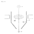
- the heating part 20C is a part where CO 2 lasers or YAG lasers entering into inside of the chamber 10 from two directions through glass windows 10B are crossed.
- the inside of the chamber 10 is in a state of inert atmosphere due to a gas for plasma. Further, the chamber 10 has an inside wall consisting of non-carbon substances (for example, a stainless inside wall).
- the heating plasma, resistance heating apparatus or laser heating apparatus works to be a heating means, and thereby, the precursor can be heated in the heating part 20A to 20C at 1300°C or higher, more preferably at 1500°C or higher.
- the silicon monoxide (SiO) gas is generated by the chemical reaction represented by the following (Formula 1). SiO 2 + C -> SiO + CO (Formula 1)
- step S104 the gas generated by heating the precursor is rapidly cooled in the inert atmosphere in the part formed by non-carbon substances.
- the silicon monoxide gas generated in the heating part 20A to 20C is released outside the heating part 20A to 20C in the chamber 10 by airflow.
- a temperature of the outside of the heating part 20A to 20C is below 1300°C, and therefore, the silicon monoxide gas can be rapidly cooled to below 1300°C. Further, the inside of the chamber 10 is maintained at a room temperature, and therefore, the silicon monoxide gas is then cooled to a room temperature rapidly.
- a composite powder containing silicon (Si) fine particles is generated by the chemical reaction represented by the following (Formula 2). 2SiO -> Si + SiO 2 (Formula 2)
- the composite powder generated by being released from the chamber 10 is collected into a cyclone dust collector, a dust collector or the like.
- the composite powder collected into the dust collector can be heated in the inert atmosphere at the temperature of 1000 to 1100°C. And an etching can be performed according to the following process.
- the heat-treated composite powder is immersed in an etching solution containing hydrofluoric acid and an oxidant.
- hydrofluoric acid for example, nitric acid (HNO 3 ) and hydrogen peroxide (H 2 O 2 ) can be used as the oxidant.
- HNO 3 nitric acid
- H 2 O 2 hydrogen peroxide
- a slightly polar solvent for example, 2-propanol
- the etching time is adjusted so that a desired emission peak can be obtained.
- the etching is proceeded until a desired emission peak is obtained. Then, the silicon fine particles are extracted from the etching solution. The extracted silicon fine particles are dried as appropriate, and thereby light-emitting silicon fine particles having a desired emission peak can be obtained.
- a high-frequency induction heating plasma apparatus 100 as shown in Fig. 5 can be used to be an apparatus for producing silicon fine particles of the present embodiment.
- Any apparatus such as a laser baking apparatus and a resistance heating baking apparatus can be used to be an apparatus for producing silicon fine particles of the present embodiment, as far as it can perform locally heating, other than the high-frequency induction heating plasma apparatus 100 shown in Fig. 5 .
- the high-frequency induction heating plasma apparatus 100 includes a torch 100A for generating plasma, and the torch 100A consists of a cylindrical member 100B, a gas ring 100C mounted on upper side of the cylindrical member 100B, an induction coil 100D placed outside the cylindrical member 100B, and the like.
- the cylindrical member 100B has a double pipe structure consisting of an inner pipe and an outer pipe, and the inner pipe consists of non-carbon substances.
- the cylindrical member 100B is mounted between a upper flange 100E and a lower flange 100F, and both the upper flange 100E and the lower flange 100F are fixed to a supporting bar 100H with a clincher 100G.
- a high-voltage generator including an ignition coil 100I and the like connects the upper flange 100E and the lower flange 100F.
- An outflow path of cooling water 100J is set on the upper flange 100E, and an inflow path of the cooling water 100K is set on the lower flange 100F.
- the cooling water is provided inside of the double pipe structure of the cylindrical member 100B through the inflow path 100K, and is discharged from the inside of the double pipe structure of the cylindrical member 100B through the outflow path 100J.
- a probe 100L is placed at a central part of the gas ring 100C.
- a probe central hole H is formed at a central part of the probe 100L along longitudinal direction of the probe 100L, and a pipe Q is inserted into the probe central hole H.
- a gas (for example, argon gas) containing the above precursor is provided inside of the cylindrical member 100B from a powder providing apparatus through the pipe Q.
- a plasma gas (for example, argon gas) is provided inside of the cylindrical member 100B from a gas source (not shown in the figure) through a providing path 100M in the gas ring 100C.
- a flow path of the cooling water (not shown in the figure) is configured in the probe 100L, and the cooling water is provided through an inlet 100N, and is discharged through an outlet 100O.
- another flow path of the cooling water 100P is configured also in the gas ring 100C, and the cooling water is provided in the flow path 100P.
- the induction coil 100D is configured so that a high-frequency power is provided from a high-frequency power source (not shown in the figure).
- a chamber 100Q is placed under the torch 100A.
- the plasma gas is provided inside of the cylindrical member 100B from the plasma gas source through a providing path 100M in the gas ring 100C.
- a high-frequency power is provided to the induction coil 100D from the high-frequency power source.
- the gas containing the above-mentioned precursor is provided to the heating part with heating plasma P through the pipe Q in the probe central hole H placed in the center of the gas ring 100C.
- the precursor is vaporized and dissolved in the heating part with heating plasma P of approximately 10000°C, and thereby, the silicon monoxide (SiO) gas is generated by the chemical reaction represented by the above-mentioned (Formula 1).
- the silicon monoxide gas generated in the heating part with heating plasma P is released from the heating part with heating plasma P to the inside of the chamber 100Q by airflow.
- the generated composite powder is collected into a dust collector connected to the chamber 100Q.
- the silicon monoxide gas which is generated by quickly heating the precursor in the inert atmosphere in the part formed by non-carbon substances by using the heating means such as heating plasma, a resistance heating apparatus, a laser heating apparatus and arc plasma, is released outside the heating part 20A to 20C to rapidly cool the gas below 1300°C (then, room temperature), and therefore, the chemical reaction represented by the following (Formula 3) occurred in a production method disclosed in the above-mentioned Patent Document 1 can be maximally avoided, and thereby yield rate of the silicon fine particles can be improved.
- the heating means such as heating plasma, a resistance heating apparatus, a laser heating apparatus and arc plasma
- the precursor in which SiO 2 and C are uniformly dispersed on the molecular level is used, and therefore, the chemical reaction represented by the above (Formula 1) adequately occurs during the precursor is released from the heating part 20A to 20C, and thereby yield rate of the silicon fine particles can be improved.
- a ratio of the silicon fine particles contained in the composite powder generated by the production method of the present invention is larger than a ratio of the silicon fine particles contained in the composite powder generated by the production method of Conventional Example.
- the method and apparatus for producing silicon fine particles of the present invention is useful because the method and apparatus can improve yield rate of the silicon fine particles.
Landscapes
- Chemical & Material Sciences (AREA)
- Organic Chemistry (AREA)
- Inorganic Chemistry (AREA)
- Chemical Kinetics & Catalysis (AREA)
- General Health & Medical Sciences (AREA)
- Toxicology (AREA)
- Health & Medical Sciences (AREA)
- Physics & Mathematics (AREA)
- Optics & Photonics (AREA)
- Electromagnetism (AREA)
- Silicon Compounds (AREA)
- Physical Or Chemical Processes And Apparatus (AREA)
- Carbon And Carbon Compounds (AREA)
Abstract
Description
- The present invention relates to a method and apparatus for producing silicon fine particles.
- Recently, with the advance in nanotechnology, a raw-material powder is sought to have a smaller particle size. The target of research and development is shifting from submicron particles to nanoparticles.
- Particularly, nanoparticles of 20 nm or smaller are known to demonstrate a peculiar electromagnetic effect along with change in an electronic state and also to have excellent properties, which a bulk material does not have, owing to an increased percentage of surface atoms and so on. For this reason, for example, silicon fine particles are expected to be used for a light-emitting element and other applications.
- Further, in the field of medicine, for example, the silicone fine particles are highly expected to be used for a light-emitting material which can be injected into a living body, because the silicone fine particles have the advantage that these are non-toxic, inexpensive and various, in addition to the property of emitting light of visible range.
- As a method for producing the above-mentioned silicon fine particles, a production method described in
Patent Document 1 is known. - In particular,
Patent Document 1 discloses a method for a composite powder containing the silicon fine particles, which has a step of baking a mixture containing a silicon source and a carbon source in an inert atmosphere to generate a gas, a step of drawing the generated gas from the inert atmosphere, and a step of rapidly cooling the generated gas. - Patent Document 1: Japanese Patent Application Publication No.
2010-195637 - According to the method for producing silicon fine particles, the following points are described in the above-mentioned
Patent Document 1. - Firstly, silicon monoxide (SiO) gas is generated as an intermediate product in a chemical reaction represented by the following formula (1).
- When continuously heating the generated silicon monoxide gas at a temperature of 1600°C or higher, silicon carbide powder is generated by a chemical reaction represented by the following formula (2).
- On the other hand, when rapidly cooling the generated silicon monoxide gas at a temperature below 1600°C, a mixture containing silicon (Si) fine particles can be obtained by a chemical reaction represented by the following formula (3).
- However, the above-mentioned production method diverts a method for producing silicon carbide (SiC).
- That is, in the above-mentioned production method, the silicon monoxide gas generated by the chemical reaction represented by the formula (1) is rapidly cooled after being drawn, and therefore, the silicon monoxide gas cannot be rapidly cooled at a temperature below 1600°C, the chemical reaction represented by the formula (2) is made progress in parallel. As a result, there is a problem that it is difficult to further improve yield rate of silicon.
- Accordingly, the present invention has been made in view of the mentioned problem. An object of the present invention is to provide a high-yield rate method and apparatus for producing silicon fine particles.
- The first feature of the present invention is a method for producing silicon fine particles which comprises a step A of heating a precursor obtained by drying a mixture containing a silicon source and a carbon source in an inert atmosphere in a part formed by non-carbon substances by using a heating means in order to generate gas, and a step B of rapidly cooling the gas generated by heating the precursor in the inert atmosphere in the part formed by non-carbon substances, wherein at least one of the silicon source and the carbon source is liquid form.
-
- [
Fig. 1] Fig. 1 is a flowchart showing a method for producing silicon fine particles according to the first embodiment of the present invention. - [
Fig. 2] Fig. 2 is an example of steps S103 and S104 which is performed in the method for producing silicon fine particles according to the first embodiment of the present invention. - [
Fig. 3] Fig. 3 is an example of steps S103 and S104 which is performed in the method for producing silicon fine particles according to the first embodiment of the present invention. - [
Fig. 4] Fig. 4 is an example of steps S103 and S104 which is performed in the method for producing silicon fine particles according to the first embodiment of the present invention. - [
Fig. 5] Fig. 5 is an example of an apparatus for producing silicon fine particles according to the first embodiment of the present invention. - [
Fig. 6] Fig 6 is a chart showing a property of silicon fine particles produced by the method for producing the silicon fine particles according to the first embodiment of the present invention. - The method and apparatus for producing silicon fine particles according to the first embodiment of the present invention will be described with reference to
Figs 1 to 4 . - As shown in
Fig. 1 , in step S101, by combining a silicon source containing at least one kind of silicon compound, and a carbon source containing at least one kind of organic compound which generates a carbon by heating to generate a mixture of the silicon source and the carbon source. - For example, the silicon source and the carbon source are combined by using an acid aqueous solution as a curing agent. As the silicon source, a liquid silicon source and a solid silicon source can be used together, but at least one liquid silicon source must be used.
- For example, as the liquid silicon source, alkoxysilanes (mono-, di-, tri-, tetra-) and polymers of tetraalkoxysilanes can be used.
- As the liquid silicon source, among the alkoxysilanes, tetraalkoxysilanes is preferably used, and in particular, methoxysilane, ethoxysilane, propoxysilane, butoxysilane, and the like can be preferably used. From the view of handling, ethoxysilane is preferably used as the liquid silicon source.
- Further, among the polypmers of tetraalkoxysilnaes, low molecular weight polymers (oligomers) having a degree of polymerization of approximately 2 to 15 and silicic acid polymers having a higher degree of polymerization can be used as the liquid silicon source.
- Silicon oxides can be used as the solid silicon source usable together with these liquid silicon sources.
- In the present embodiment, the silicon oxide include, besides SiO, silica gels (colloidal ultrafine silica-containing solution containing an OH group and an alkoxy group therein), silicon dioxide (silica gel, fine silica, quartz powder), and the like.
- These silicon sources can be used singly, or in combination of two or more kinds. Among these silicon sources, tetraethoxysilane oligomer, mixtures of tetraethoxysilane oligomer and fine powder silica, and the like are preferable from the viewpoint of homogeneity and handling.
- A substance used as the carbon source is preferably an organic compound containing oxygen therein, and which keeps carbon when it is heated.
- In particular, phenolic resins, furan resins, epoxy resins, phenoxy resins, and sugars including monosaccharides such as glucose, oligosaccharides such as sucrose, and polysaccharides such as cellulose and starch are exemplified.
- In order to combine these carbon sources with the silicon sources homogenously, carbon sources, which are liquid form at a normal temperature, dissolvable into a solvent, and soften and liquefy by heating as with a thermoplastic or thermal melting substance, are mainly used.
- Among these, resol-type phenolic resins or novolac-type phenolic resins are preferably used. In particular, resol-type phenolic resins are preferably used.
- A curing agent can be appropriately selected depending on the carbon sources. For example, when the carbon source is the phenolic resins or furan resins, a weak acid aqueous solution such as toluenesulfonic acid aqueous solution, toluenecarboxylic acid aqueous solution, acetic acid aqueous solution, oxalic acid aqueous solution, sulfuric acid aqueous solution and the like can be used as the curing agent. Among these, toluenesulfonic acid, maleic acid, hydrochloric acid and the like are preferably used as the curing agent.
- Note that at least one of the silicon sources and the carbon sources which are used for generating the above-mentioned mixture must be in liquid form.
- In step S102, a precursor in solid form is generated by drying the mixture obtained in step S101 at a temperature of 100 to 300°C.
- As mentioned above, because at least one of the silicon sources and the carbon sources contained in the mixture which is used for generating the precursor is in liquid form, SiO2 and C are uniformly dispersed in inner portion of the precursor on the molecular level.
- Because various organic components are contained in the precursor, the precursor can be carbonized at 500 to 1300°C in a non-oxidizing atmosphere.
- For example, the mixture ratio between carbon and silicon in the precursor (hereinafter abbreviated to C/Si ratio) is preferably 0.5 to 3.0, more preferably 0.75 to 1.5.
- In step S103, the carbonized precursor is heated in an inert atmosphere in a part formed by non-carbon substances.
- The non-carbon substances can be a substance containing carbon unless the carbon is not exposed on the surface of the non-carbon substances. For example, substance having a strong carbon bond such as SiC, and substance which sublimates at very high temperature, and thereby C contained in the substance does not sublimate, can be used as the non-carbon substances.
- The inert atmosphere represents a state filled with an inert gas such as Ar, N2 and H2. Note that an active gas such as O2 can be contained in the inert atmosphere as far as in a slight amount that the active gas does not affect the property of the inert atmosphere.
- In particular, in step S103, the carbonized precursor can be heated by using heating plasma, a resistance heating apparatus, a laser heating apparatus, arc plasma and the like.
- For example, as shown in
Fig. 2 , after finely pulverizing the precursor, a gas containing the precursor can be sprayed to aheating part 20A generated by heated plasma in achamber 10 by using a powder providing apparatus such as a table feeder and screw feeder. - Alternatively, as shown in
Fig. 3 , after finely pulverizing the precursor, the gas containing the precursor can be sprayed to aheating part 20B generated by the resistance heating apparatus in thechamber 10 by using the powder providing apparatus such as the table feeder and screw feeder. - Alternatively, as shown in
Fig. 4 (a) and Fig. 4(b) , after finely pulverizing the precursor, the gas containing the precursor can be sprayed to aheating part 20C generated by the laser heating apparatus in thechamber 10 by using the powder providing apparatus such as the table feeder and screw feeder. - As shown in
Fig. 4 (a) and Fig. 4 (b) , theheating part 20C is a part where CO2 lasers or YAG lasers entering into inside of thechamber 10 from two directions throughglass windows 10B are crossed. - The inside of the
chamber 10 is in a state of inert atmosphere due to a gas for plasma. Further, thechamber 10 has an inside wall consisting of non-carbon substances (for example, a stainless inside wall). - In the above case, the heating plasma, resistance heating apparatus or laser heating apparatus works to be a heating means, and thereby, the precursor can be heated in the
heating part 20A to 20C at 1300°C or higher, more preferably at 1500°C or higher. As a result, the silicon monoxide (SiO) gas is generated by the chemical reaction represented by the following (Formula 1).
SiO2 + C -> SiO + CO (Formula 1)
- In step S104, the gas generated by heating the precursor is rapidly cooled in the inert atmosphere in the part formed by non-carbon substances.
- In particular, as shown in
Fig. 2 to Fig. 4 , for example, the silicon monoxide gas generated in theheating part 20A to 20C is released outside theheating part 20A to 20C in thechamber 10 by airflow. - In this case, a temperature of the outside of the
heating part 20A to 20C is below 1300°C, and therefore, the silicon monoxide gas can be rapidly cooled to below 1300°C. Further, the inside of thechamber 10 is maintained at a room temperature, and therefore, the silicon monoxide gas is then cooled to a room temperature rapidly. As a result, a composite powder containing silicon (Si) fine particles is generated by the chemical reaction represented by the following (Formula 2).
2SiO -> Si + SiO2 (Formula 2)
- The composite powder generated by being released from the
chamber 10 is collected into a cyclone dust collector, a dust collector or the like. - The composite powder collected into the dust collector can be heated in the inert atmosphere at the temperature of 1000 to 1100°C. And an etching can be performed according to the following process. In particular, the heat-treated composite powder is immersed in an etching solution containing hydrofluoric acid and an oxidant. For example, nitric acid (HNO3) and hydrogen peroxide (H2O2) can be used as the oxidant. A slightly polar solvent (for example, 2-propanol) may be mixed with the etching solution to facilitate recovery of the silicon fine particles.
- The etching time is adjusted so that a desired emission peak can be obtained. The longer the etching time is, the more likely the emission peak shifts to a shorter wavelength side.
- The etching is proceeded until a desired emission peak is obtained. Then, the silicon fine particles are extracted from the etching solution. The extracted silicon fine particles are dried as appropriate, and thereby light-emitting silicon fine particles having a desired emission peak can be obtained.
- Hereinafter, an example of an apparatus for producing silicon fine particles of a first embodiment of the present invention will be described with reference to
Fig. 5 . - A high-frequency induction
heating plasma apparatus 100 as shown inFig. 5 can be used to be an apparatus for producing silicon fine particles of the present embodiment. Any apparatus such as a laser baking apparatus and a resistance heating baking apparatus can be used to be an apparatus for producing silicon fine particles of the present embodiment, as far as it can perform locally heating, other than the high-frequency inductionheating plasma apparatus 100 shown inFig. 5 . - As shown in
Fig. 5 , the high-frequency inductionheating plasma apparatus 100 includes atorch 100A for generating plasma, and thetorch 100A consists of acylindrical member 100B, agas ring 100C mounted on upper side of thecylindrical member 100B, aninduction coil 100D placed outside thecylindrical member 100B, and the like. - The
cylindrical member 100B has a double pipe structure consisting of an inner pipe and an outer pipe, and the inner pipe consists of non-carbon substances. - The
cylindrical member 100B is mounted between aupper flange 100E and alower flange 100F, and both theupper flange 100E and thelower flange 100F are fixed to a supportingbar 100H with aclincher 100G. - A high-voltage generator including an ignition coil 100I and the like connects the
upper flange 100E and thelower flange 100F. - An outflow path of cooling
water 100J is set on theupper flange 100E, and an inflow path of the coolingwater 100K is set on thelower flange 100F. - The cooling water is provided inside of the double pipe structure of the
cylindrical member 100B through theinflow path 100K, and is discharged from the inside of the double pipe structure of thecylindrical member 100B through theoutflow path 100J. - A
probe 100L is placed at a central part of thegas ring 100C. A probe central hole H is formed at a central part of theprobe 100L along longitudinal direction of theprobe 100L, and a pipe Q is inserted into the probe central hole H. - A gas (for example, argon gas) containing the above precursor is provided inside of the
cylindrical member 100B from a powder providing apparatus through the pipe Q. - A plasma gas (for example, argon gas) is provided inside of the
cylindrical member 100B from a gas source (not shown in the figure) through a providing path 100M in thegas ring 100C. - Further, a flow path of the cooling water (not shown in the figure) is configured in the
probe 100L, and the cooling water is provided through aninlet 100N, and is discharged through an outlet 100O. - Further, another flow path of the
cooling water 100P is configured also in thegas ring 100C, and the cooling water is provided in theflow path 100P. - The
induction coil 100D is configured so that a high-frequency power is provided from a high-frequency power source (not shown in the figure). - Further, a
chamber 100Q is placed under thetorch 100A. - Hereinafter, behavior of the high-frequency induction
heating plasma apparatus 100 will be briefly described. - In the first place, the plasma gas is provided inside of the
cylindrical member 100B from the plasma gas source through a providing path 100M in thegas ring 100C. In addition, a high-frequency power is provided to theinduction coil 100D from the high-frequency power source. - In the second place, when a high voltage is applied between the
upper flange 100E and thelower flange 100F from the high-voltage generating apparatus 100I in the above-mentioned state, corona discharge is generated between theupper flange 100E and thelower flange 100F, which triggers generation of a heating plasma P in thetorch 100A (ignition). - In the fourth place, the gas containing the above-mentioned precursor is provided to the heating part with heating plasma P through the pipe Q in the probe central hole H placed in the center of the
gas ring 100C. - In the fifth place, the precursor is vaporized and dissolved in the heating part with heating plasma P of approximately 10000°C, and thereby, the silicon monoxide (SiO) gas is generated by the chemical reaction represented by the above-mentioned (Formula 1).
- In the sixth place, the silicon monoxide gas generated in the heating part with heating plasma P is released from the heating part with heating plasma P to the inside of the
chamber 100Q by airflow. - As a result of rapid cooling of the silicon monoxide in the
chamber 100Q, a composite powder containing the silicon (Si) fine particles is generated by the chemical reaction represented by the above-mentioned (Formula 2). - In the sixth place, the generated composite powder is collected into a dust collector connected to the
chamber 100Q. - According to the method for producing silicon fine particles of the first embodiment of the present invention, the silicon monoxide gas, which is generated by quickly heating the precursor in the inert atmosphere in the part formed by non-carbon substances by using the heating means such as heating plasma, a resistance heating apparatus, a laser heating apparatus and arc plasma, is released outside the
heating part 20A to 20C to rapidly cool the gas below 1300°C (then, room temperature), and therefore, the chemical reaction represented by the following (Formula 3) occurred in a production method disclosed in the above-mentionedPatent Document 1 can be maximally avoided, and thereby yield rate of the silicon fine particles can be improved.
SiO + 2C -> SiC + CO (Formula 3)
- Further, according to the method for producing silicon fine particles of the first embodiment of the present invention, the precursor in which SiO2 and C are uniformly dispersed on the molecular level is used, and therefore, the chemical reaction represented by the above (Formula 1) adequately occurs during the precursor is released from the
heating part 20A to 20C, and thereby yield rate of the silicon fine particles can be improved. - To further clarify an effect of the present invention, the production method of the present invention was compared with the production method disclosed in the above Patent Document 1 (Conventional Example) in terms of yield amount and yield rate of produced silicon fine particles. A comparative result is shown in Table 1.
[Table 1] Raw materials Products Si content Yield rate Conventional Example 50g 2g 0.1 g (5%) 0.2% Example 100g 40g 16g (40%) 16% - As shown in Table 1, in Conventional Example, when a total amount of silicon source and carbon source (raw materials) was 50g, a weight of the composite powder (products) as mentioned above was 2g, and a weight of the silicon fine particles contained in the composite powder was 0.1g. That is, yield rate of the silicon fine particles in Conventional Example was 0.2%.
- On the other hand, in the production method of the present invention, when total amount of silicon source and carbon source (raw materials) was 100g, a weight of the composite powder (products) as mentioned above was 40g, and a weight of the silicon fine particles contained in the composite powder was 16g. That is, yield rate of the silicon fine particles in Example was 16%.
- As evidenced by chart of
Fig. 6 , a ratio of the silicon fine particles contained in the composite powder generated by the production method of the present invention is larger than a ratio of the silicon fine particles contained in the composite powder generated by the production method of Conventional Example. - As mentioned above, the present invention is explained in detail by exemplifying the above embodiment. However, it is clearly understood by one skilled in the art that the present invention is not limited to the embodiment described in the present specification. The present invention can be implemented as a corrected and modified mode without departing from the gist and the scope of the present invention defined by the claims. Therefore, the description of the specification is intended for explaining the example only and does not impose any limited meaning to the present invention.
- All the contents of Japanese Patent Application No.
2011-279733 (filed on December 21, 2011 - As has been described above, the method and apparatus for producing silicon fine particles of the present invention is useful because the method and apparatus can improve yield rate of the silicon fine particles.
SiO2 + C → SiO + CO (1)
SiO + 2C → SiC + CO (2)
2SiO -> Si + SiO2 (3)
Claims (5)
- A method for producing silicon fine particles, comprising:a step A of heating a precursor obtained by drying a mixture containing a silicon source and a carbon source in an inert atmosphere in a part formed by non-carbon substances by using a heating means,a step B of rapidly cooling a gas generated by heating the precursor in the inert atmosphere in the part formed by non-carbon substances,wherein at least one of the silicon source and the carbon source is liquid form.
- The method for producing silicon fine particles according to claim 1, wherein, in the step A, the precursor is heated in a chamber having an inside wall consisting of non-carbon substances by using heating plasma, a resistance heating apparatus, a laser heating apparatus or arc plasma as the heating means.
- An apparatus for producing silicon fine particles, comprising:a heating means configured to heat a precursor obtained by drying a mixture containing a silicon source and a carbon source in an inert atmosphere in a part formed by non-carbon substances,a rapid cooling means configured to rapidly cool a gas generated by heating the precursor in the inert atmosphere in the part formed by non-carbon substances,wherein at least one of the silicon source and the carbon source is liquid form.
- The apparatus for producing silicon fine particles according to claim 3, wherein the heating means is configured to heat the precursor in a chamber having an inside wall consisting of non-carbon substances by using heating plasma, a resistance heating apparatus, a laser heating apparatus or arc plasma.
- The apparatus for producing silicon fine particles according to claim 4, wherein the rapid cooling means is configured to rapidly cool the gas by releasing the gas outside the heating part where the precursor is heated by the heating means.
Applications Claiming Priority (2)
| Application Number | Priority Date | Filing Date | Title |
|---|---|---|---|
| JP2011279733A JP2013129558A (en) | 2011-12-21 | 2011-12-21 | Method and apparatus for producing silicon fine particle |
| PCT/JP2012/081935 WO2013094458A1 (en) | 2011-12-21 | 2012-12-10 | Method and apparatus for producing silicon microparticles |
Publications (2)
| Publication Number | Publication Date |
|---|---|
| EP2796409A1 true EP2796409A1 (en) | 2014-10-29 |
| EP2796409A4 EP2796409A4 (en) | 2015-09-23 |
Family
ID=48668352
Family Applications (1)
| Application Number | Title | Priority Date | Filing Date |
|---|---|---|---|
| EP12858883.7A Withdrawn EP2796409A4 (en) | 2011-12-21 | 2012-12-10 | Method and apparatus for producing silicon microparticles |
Country Status (6)
| Country | Link |
|---|---|
| US (1) | US20150004090A1 (en) |
| EP (1) | EP2796409A4 (en) |
| JP (1) | JP2013129558A (en) |
| CN (1) | CN104010967A (en) |
| TW (1) | TWI488806B (en) |
| WO (1) | WO2013094458A1 (en) |
Families Citing this family (4)
| Publication number | Priority date | Publication date | Assignee | Title |
|---|---|---|---|---|
| CN103833035B (en) * | 2014-03-06 | 2017-01-11 | 台州市一能科技有限公司 | Preparation method of silicon carbide |
| CN104773737B (en) * | 2015-03-20 | 2017-04-19 | 天水佳吉化工有限公司 | Production method for fine spherical silicon powder |
| CN114583122A (en) * | 2022-01-30 | 2022-06-03 | 合肥国轩高科动力能源有限公司 | Carbon-silicon negative electrode material, preparation method thereof and lithium ion battery |
| FR3151321A1 (en) * | 2023-07-19 | 2025-01-24 | Renault S.A.S | Process for forming silicon from silica and passivated silicon |
Family Cites Families (8)
| Publication number | Priority date | Publication date | Assignee | Title |
|---|---|---|---|---|
| CN1207192C (en) * | 1997-12-25 | 2005-06-22 | 新日本制铁株式会社 | Process for prepn. of High-purity si and equipment therefor |
| JP4980603B2 (en) * | 2005-10-19 | 2012-07-18 | 株式会社ブリヂストン | Method for producing silicon fine particles |
| US20080314446A1 (en) * | 2007-06-25 | 2008-12-25 | General Electric Company | Processes for the preparation of solar-grade silicon and photovoltaic cells |
| JP5465884B2 (en) * | 2009-01-05 | 2014-04-09 | 株式会社ブリヂストン | Method for producing mixed powder containing silicon fine particles |
| JP5261230B2 (en) | 2009-02-25 | 2013-08-14 | 株式会社ブリヂストン | Method for producing silicon fine particle light emitter |
| JP5370055B2 (en) * | 2009-10-06 | 2013-12-18 | 住友大阪セメント株式会社 | Method for producing silicon lower oxide particles and dispersion of the particles |
| KR101442373B1 (en) * | 2010-03-12 | 2014-09-17 | 가부시키가이샤 브리지스톤 | Light-emitting body containing silicon microparticles and method for producing silicon microparticle light-emitting body |
| JP2013171628A (en) * | 2012-02-17 | 2013-09-02 | Bridgestone Corp | Manufacturing method and manufacturing apparatus of negative electrode material for nonaqueous electrolyte secondary battery |
-
2011
- 2011-12-21 JP JP2011279733A patent/JP2013129558A/en not_active Withdrawn
-
2012
- 2012-12-10 WO PCT/JP2012/081935 patent/WO2013094458A1/en not_active Ceased
- 2012-12-10 EP EP12858883.7A patent/EP2796409A4/en not_active Withdrawn
- 2012-12-10 CN CN201280063138.5A patent/CN104010967A/en active Pending
- 2012-12-10 US US14/367,138 patent/US20150004090A1/en not_active Abandoned
- 2012-12-20 TW TW101148582A patent/TWI488806B/en not_active IP Right Cessation
Also Published As
| Publication number | Publication date |
|---|---|
| US20150004090A1 (en) | 2015-01-01 |
| EP2796409A4 (en) | 2015-09-23 |
| TW201343550A (en) | 2013-11-01 |
| CN104010967A (en) | 2014-08-27 |
| WO2013094458A1 (en) | 2013-06-27 |
| JP2013129558A (en) | 2013-07-04 |
| TWI488806B (en) | 2015-06-21 |
Similar Documents
| Publication | Publication Date | Title |
|---|---|---|
| JP5667099B2 (en) | Particle synthesis equipment | |
| JP4649586B2 (en) | Production method of SiC nanoparticles by nitrogen plasma | |
| JP4700835B2 (en) | Silicon carbide powder, method for producing the same, and silicon carbide sintered body | |
| CN102171142A (en) | Production of solar-grade silicon from silicon dioxide | |
| US20150004090A1 (en) | Method and apparatus for producing silicon fine particles | |
| CN103056388A (en) | Method for preparing aluminum nanoparticles coated with dispersion stabilizers by liquid-phase chemical reduction method | |
| JP4980603B2 (en) | Method for producing silicon fine particles | |
| US20120156392A1 (en) | Oriented carbon nanotube manufacturing method | |
| CN109437162B (en) | Method for producing reduced graphene oxide | |
| JP5563755B2 (en) | Method for producing silicon fine particle light emitter | |
| CN114566327B (en) | Alloy powder production method, alloy powder prepared by method, slurry and capacitor | |
| WO2000045621A1 (en) | Carbon-based heating unit and method for preparation thereof | |
| JP5261230B2 (en) | Method for producing silicon fine particle light emitter | |
| JP2014156365A (en) | Method for producing fine silicon particle | |
| JP2014156363A (en) | Method for producing fine silicon particle | |
| KR101442373B1 (en) | Light-emitting body containing silicon microparticles and method for producing silicon microparticle light-emitting body | |
| JP5303103B2 (en) | Silicon carbide sintered body and method for producing the same | |
| Han et al. | Active chemical furnace‐assisted combustion synthesis of SiC nanoparticles with in situ spontaneous granulation | |
| KR101460497B1 (en) | Titanium oxide-carbon nanotube composite with controllable thermal property and manufacturing method of the same | |
| KR101897037B1 (en) | Method of fabricating silicon carbide powder | |
| JP5130099B2 (en) | Method for producing sintered silicon carbide | |
| WO2008071504A2 (en) | Porous silicon | |
| KR102172600B1 (en) | Manufacturing method of silicon nitride having excellent heat dissipation properties | |
| JP4014561B2 (en) | Aluminum nitride powder, production method and use thereof | |
| JP2014156364A (en) | Method for producing fine silicon carbide particle |
Legal Events
| Date | Code | Title | Description |
|---|---|---|---|
| PUAI | Public reference made under article 153(3) epc to a published international application that has entered the european phase |
Free format text: ORIGINAL CODE: 0009012 |
|
| 17P | Request for examination filed |
Effective date: 20140721 |
|
| AK | Designated contracting states |
Kind code of ref document: A1 Designated state(s): AL AT BE BG CH CY CZ DE DK EE ES FI FR GB GR HR HU IE IS IT LI LT LU LV MC MK MT NL NO PL PT RO RS SE SI SK SM TR |
|
| RIN1 | Information on inventor provided before grant (corrected) |
Inventor name: IWABUCHI, YOSHINORI Inventor name: YAMAMOTO, YUKIKO Inventor name: ENDO, SHINOBU |
|
| DAX | Request for extension of the european patent (deleted) | ||
| RIC1 | Information provided on ipc code assigned before grant |
Ipc: B01J 19/08 20060101ALI20150811BHEP Ipc: B01J 19/12 20060101ALI20150811BHEP Ipc: C01B 31/36 20060101ALI20150811BHEP Ipc: C01B 33/025 20060101AFI20150811BHEP Ipc: H01M 4/36 20060101ALI20150811BHEP Ipc: H01M 4/48 20100101ALI20150811BHEP |
|
| RA4 | Supplementary search report drawn up and despatched (corrected) |
Effective date: 20150821 |
|
| STAA | Information on the status of an ep patent application or granted ep patent |
Free format text: STATUS: THE APPLICATION IS DEEMED TO BE WITHDRAWN |
|
| 18D | Application deemed to be withdrawn |
Effective date: 20160319 |