EP2796367B1 - Fixation de pale d'hélice - Google Patents
Fixation de pale d'hélice Download PDFInfo
- Publication number
- EP2796367B1 EP2796367B1 EP14154449.4A EP14154449A EP2796367B1 EP 2796367 B1 EP2796367 B1 EP 2796367B1 EP 14154449 A EP14154449 A EP 14154449A EP 2796367 B1 EP2796367 B1 EP 2796367B1
- Authority
- EP
- European Patent Office
- Prior art keywords
- cheeks
- arrangement
- collar
- propeller blade
- propeller
- Prior art date
- Legal status (The legal status is an assumption and is not a legal conclusion. Google has not performed a legal analysis and makes no representation as to the accuracy of the status listed.)
- Active
Links
- 230000014759 maintenance of location Effects 0.000 title claims description 27
- 230000000295 complement effect Effects 0.000 claims description 14
- 230000008859 change Effects 0.000 claims description 12
- 229910052751 metal Inorganic materials 0.000 claims description 12
- 239000002184 metal Substances 0.000 claims description 12
- 239000002131 composite material Substances 0.000 claims description 11
- 230000007246 mechanism Effects 0.000 claims description 7
- 239000011156 metal matrix composite Substances 0.000 claims description 7
- 239000000853 adhesive Substances 0.000 claims description 3
- 230000001070 adhesive effect Effects 0.000 claims description 3
- 230000007704 transition Effects 0.000 claims description 3
- XAGFODPZIPBFFR-UHFFFAOYSA-N aluminium Chemical compound [Al] XAGFODPZIPBFFR-UHFFFAOYSA-N 0.000 description 4
- 239000004411 aluminium Substances 0.000 description 4
- 229910052782 aluminium Inorganic materials 0.000 description 4
- 239000000463 material Substances 0.000 description 4
- 238000007493 shaping process Methods 0.000 description 4
- RTAQQCXQSZGOHL-UHFFFAOYSA-N Titanium Chemical compound [Ti] RTAQQCXQSZGOHL-UHFFFAOYSA-N 0.000 description 3
- 238000002485 combustion reaction Methods 0.000 description 3
- 239000000835 fiber Substances 0.000 description 3
- 239000000203 mixture Substances 0.000 description 3
- 239000010936 titanium Substances 0.000 description 3
- 229910052719 titanium Inorganic materials 0.000 description 3
- 230000000712 assembly Effects 0.000 description 2
- 238000000429 assembly Methods 0.000 description 2
- 238000005452 bending Methods 0.000 description 2
- 239000004519 grease Substances 0.000 description 2
- 238000007689 inspection Methods 0.000 description 2
- 238000012423 maintenance Methods 0.000 description 2
- 238000004519 manufacturing process Methods 0.000 description 2
- 238000000034 method Methods 0.000 description 2
- 230000000750 progressive effect Effects 0.000 description 2
- 230000001141 propulsive effect Effects 0.000 description 2
- HBMJWWWQQXIZIP-UHFFFAOYSA-N silicon carbide Chemical compound [Si+]#[C-] HBMJWWWQQXIZIP-UHFFFAOYSA-N 0.000 description 2
- 229910010271 silicon carbide Inorganic materials 0.000 description 2
- XLYOFNOQVPJJNP-UHFFFAOYSA-N water Substances O XLYOFNOQVPJJNP-UHFFFAOYSA-N 0.000 description 2
- 238000003466 welding Methods 0.000 description 2
- 229910000906 Bronze Inorganic materials 0.000 description 1
- OKTJSMMVPCPJKN-UHFFFAOYSA-N Carbon Chemical compound [C] OKTJSMMVPCPJKN-UHFFFAOYSA-N 0.000 description 1
- NPXOKRUENSOPAO-UHFFFAOYSA-N Raney nickel Chemical compound [Al].[Ni] NPXOKRUENSOPAO-UHFFFAOYSA-N 0.000 description 1
- 238000010521 absorption reaction Methods 0.000 description 1
- 239000000654 additive Substances 0.000 description 1
- 230000000996 additive effect Effects 0.000 description 1
- AZDRQVAHHNSJOQ-UHFFFAOYSA-N alumane Chemical group [AlH3] AZDRQVAHHNSJOQ-UHFFFAOYSA-N 0.000 description 1
- 238000005219 brazing Methods 0.000 description 1
- 239000010974 bronze Substances 0.000 description 1
- 229910052799 carbon Inorganic materials 0.000 description 1
- 230000006835 compression Effects 0.000 description 1
- 238000007906 compression Methods 0.000 description 1
- 230000032798 delamination Effects 0.000 description 1
- 230000008021 deposition Effects 0.000 description 1
- 230000000694 effects Effects 0.000 description 1
- 230000003628 erosive effect Effects 0.000 description 1
- 238000005187 foaming Methods 0.000 description 1
- 230000008014 freezing Effects 0.000 description 1
- 238000007710 freezing Methods 0.000 description 1
- 239000000446 fuel Substances 0.000 description 1
- 230000006872 improvement Effects 0.000 description 1
- 238000005304 joining Methods 0.000 description 1
- 239000011159 matrix material Substances 0.000 description 1
- 230000002093 peripheral effect Effects 0.000 description 1
- 230000008439 repair process Effects 0.000 description 1
- 238000000926 separation method Methods 0.000 description 1
- 238000003756 stirring Methods 0.000 description 1
- 238000005728 strengthening Methods 0.000 description 1
- 229920001169 thermoplastic Polymers 0.000 description 1
- 229920001187 thermosetting polymer Polymers 0.000 description 1
- 230000008719 thickening Effects 0.000 description 1
- 238000009941 weaving Methods 0.000 description 1
Images


Classifications
-
- B—PERFORMING OPERATIONS; TRANSPORTING
- B64—AIRCRAFT; AVIATION; COSMONAUTICS
- B64C—AEROPLANES; HELICOPTERS
- B64C11/00—Propellers, e.g. of ducted type; Features common to propellers and rotors for rotorcraft
- B64C11/02—Hub construction
- B64C11/04—Blade mountings
-
- B—PERFORMING OPERATIONS; TRANSPORTING
- B64—AIRCRAFT; AVIATION; COSMONAUTICS
- B64C—AEROPLANES; HELICOPTERS
- B64C11/00—Propellers, e.g. of ducted type; Features common to propellers and rotors for rotorcraft
- B64C11/16—Blades
- B64C11/20—Constructional features
- B64C11/26—Fabricated blades
Definitions
- the present invention relates to a retention arrangement for a propeller blade. It has particular, but not exclusive, utility for retaining a propeller blade comprising composite material.
- a propeller blade generally forms one of an array of such blades mounted to a hub about which they rotate in use.
- the hub may be aligned with the axis of the engine which drives the rotation or may be offset therefrom using gearboxes or the like.
- the centrifugal forces generated by rotation of the array of blades try to cause each blade to be expelled radially.
- a retention arrangement is required to hold the propeller blade in correct relation with the hub.
- the pitch of the propeller blades can be varied, meaning that the propeller blade can be rotated about its own longitudinal axis to change the incident angle the blade portion forms with free-stream airflow, the retention problem is increased since the propeller blades cannot be rigidly mounted to the hub.
- GB 291 906 discloses a propeller blade retention for a metal propeller blade.
- a portion of the blade shank is tapered.
- a conical collar which is externally threaded, and longitudinally split into two or more portions, fits against the tapered shank.
- An internally threaded nut is screwed onto the collar to retain the arrangement together.
- US 2011/0129345 and US 2010/104443 teach retaining the root portion of a composite propeller blade in an intermediate material and then a metal collar.
- the intermediate portion is flared to prevent it from sliding out of the metal collar due to the centrifugal forces.
- the composite fibres are separated by and bonded to wedges to match the flare of the intermediate portion.
- first engine order propeller couples These result from the once per revolution change in incidence angle, and therefore lift, of the individual propeller blades when the incoming airflow is not aligned with the engine axis.
- the couples are transferred from the aerofoil into the hub via differential vertical loading of a thrust bearing and differential side loading of the thrust and taper roller bearings.
- the thrust bearing is radially outward of the flared part and therefore relatively close to the taper roller bearing so that the bearing side loads are large and the first engine order couples are reduced. This also increases the thrust bearing differential radial loading which consequently increases the risk of high cycle fatigue damage to the hub thrust bearing retaining features.
- the present invention provides a propeller blade retention arrangement that seeks to address the aforementioned problems.
- a propeller blade retention arrangement comprising:
- the present invention provides good retention of the root portion of the propeller blade, reduces the loading by increasing the radial distance of the retention arrangement over which it is spread, and improves the torque transfer capability.
- the integral penny acts as a heat shield to the retention arrangement and root portion, provides a smooth gas-washed surface whatever the blade pitch and may be arranged to preferentially fail to protect trailing blades in the event of propeller blade release.
- the cheeks may have equal circumferential extent. Advantageously this prevents re-entrant assembly difficulties.
- the inner surface of each cheek may be arranged to complement the aerofoil portion camber.
- a first cheek may be arranged to match a pressure side of the aerofoil portion and a second cheek may be arranged to match a suction side of the aerofoil portion.
- the cheeks therefore abut in line with the leading and trailing edges of the aerofoil portion of the propeller blade.
- the inner surfaces of the at least two cheeks and the root portion outer surface each comprise complementary interlock features.
- the complementary interlock features may comprise radial undulations or circumferential undulations.
- the edge surfaces of the at least two cheeks may comprise complementary interlock features.
- this may assist assembly by securing, at least temporarily, the cheeks together before the collar is screwed onto the outer surfaces of the cheeks.
- the complementary interlock features may comprise undulations (radial or axial), or pins and recesses.
- the collar may be annular.
- the collar is therefore well adapted for engagement with other components such as bearings and seals.
- the collar may be coupled to a pitch change mechanism.
- the outer surface thread direction may be arranged to tighten the collar and cheeks during normal use of the propeller blade.
- this the threads tighten as the centrifugal turning moment tries to change the blade pitch towards fine in normal use.
- Each cheek may comprise a flange.
- the flange may be located intermediate the integral penny and the thread.
- the collar may comprise a flange.
- the cheek flange and the collar flange may be joined together. They may be joined together by any of: bolts, dowels, rivets, adhesive, welds, straking.
- Advantageously joining the flanges improves the torque transfer.
- the first cross-sectional area may have elongated curved periphery. It may be oval or elliptical. Alternatively it may have semi-circular, semi-oval or semi-elliptical ends joined by straight or curved sides.
- the shape of the first cross-sectional area provides good centrifugal turning moment torque transfer from the propeller blade to the cheeks.
- the second cross-sectional area may have circular periphery.
- this offers a simple assembly shape.
- the root portion may comprise a composite material, which may be fibre-reinforced.
- the propeller blade may comprise a composite material, which may be fibre-reinforced.
- the fibres may be different lengths and orientations for different portions of the propeller blade.
- an integrally formed structure is stronger than multiple portions that are separately formed and subsequently joined together.
- the collar may comprise metal.
- the cheeks may comprise metal, such as titanium or aluminium; metal matrix composite, such as a titanium or aluminium core formed by foaming (including self-skinned) or by additive manufacturing methods (including direct laser deposition); or particulate reinforced metal matrix composite, such as silicon carbide particulate reinforced aluminium metal matrix composite.
- metal such as titanium or aluminium
- metal matrix composite such as a titanium or aluminium core formed by foaming (including self-skinned) or by additive manufacturing methods (including direct laser deposition)
- particulate reinforced metal matrix composite such as silicon carbide particulate reinforced aluminium metal matrix composite.
- the present invention also provides a propeller assembly comprising an array of arrangements as described, an engine comprising one or more such propeller assemblies and a propeller gas turbine engine comprising one or more such propeller assemblies.
- a twin-spooled, contra-rotating propeller gas turbine engine is generally indicated at 10 and has a principal rotational axis 9.
- the engine 10 comprises a core engine 11 having, in axial flow series, an air intake 12, an intermediate pressure compressor 14, a high-pressure compressor 15, combustion equipment 16, a high-pressure turbine 17, an intermediate pressure turbine 18, a free power (or low-pressure) turbine 19 and a core exhaust nozzle 20.
- a nacelle 21 generally surrounds the core engine 11 and defines the intake 12 and nozzle 20 and a core exhaust duct 22.
- the engine 10 also comprises two contra-rotating propeller stages 23, 24 attached to and driven by the free power turbine 19 via shaft 26.
- the gas turbine engine 10 works in a conventional manner so that air entering the intake 12 is accelerated and compressed by the intermediate pressure compressor 14 and directed into the high-pressure compressor 15 where further compression takes place.
- the compressed air exhausted from the high-pressure compressor 15 is directed into the combustion equipment 16 where it is mixed with fuel and the mixture combusted.
- the resultant hot combustion products then expand through, and thereby drive the high-pressure, intermediate pressure and free power turbines 17, 18, 19 before being exhausted through the nozzle 20 to provide some propulsive thrust.
- the high-pressure, intermediate pressure and free power turbines 17, 18, 19 respectively drive the high and intermediate pressure compressors 15, 14 and the propellers 23, 24 by suitable interconnecting shafts.
- the propellers 23, 24 normally provide the majority of the propulsive thrust.
- the propellers 23, 24 may rotate in opposite senses so that one rotates clockwise and the other anti-clockwise around the engine's rotational axis 9.
- the propellers 23, 24 each comprise a hub and a plurality of propeller blades 28 arranged in a regular circumferential array about the hub.
- Each propeller blade 28 has a longitudinal axis L which coincides with the radial direction of the engine 10 where the hub's rotational axis is coincident with the engine's rotational axis 9.
- Each propeller blade 28 is arranged to rotate about its longitudinal axis L to change its pitch which is effected by a suitable pitch change mechanism (not shown).
- pitch change may require radially spaced bearing arrangements, for example a roller bearing arrangement and a ball bearing arrangement, to convert linear movement of pitch change rods to rotation of the propeller blade 28 about the longitudinal axis L. This may be achieved by a crank lever (not shown) moving about longitudinal axis L to convert the linear movement of the pitch change rods to the pitch rotation.
- FIG. 2 illustrates the detail of the radially inner end of a propeller blade 28 and a retention arrangement 30 according to the present invention.
- the propeller blade 28 comprises an aerofoil portion 32, a root fillet 34, a shank portion 35 and a root portion 36.
- the propeller blade 28 is formed of composite material.
- the propeller blade 28 may comprise fibre reinforced composite, with some lengths of fibre approximately aligned with the longitudinal axis L.
- it may comprise carbon fibres in a thermosetting or thermoplastic polymer matrix.
- the aerofoil portion 32 may be clad with a metal skin, for example on the leading edge, to protect against erosion.
- the metal skin may extend to clad the root fillet 34 also or may end before the root fillet 34 to expose an anti-ice heater.
- shank portion 35 and root portion 36 preferably have smooth outside surfaces without corners. There is thus a radius or fillet between the root fillet 34 and the shank portion 35 at the leading and trailing edges.
- the root portion 36 has varying cross-sectional area, being the area perpendicular to the longitudinal axis L.
- the first cross-sectional area 38 is located where the shank portion 35 blends into the root portion 36.
- it has an oval or elliptical periphery.
- it may have peripheral shape formed by the intersection of two semi-circular or elliptical ends with straight sides. The sides may be curved with a large radius of curvature.
- the second cross-sectional area 40 is located at the radially inner end of the root portion 36. In preferred embodiments it has circular periphery.
- the second cross-sectional area 40 is greater than the first cross-sectional area 38 so that the root portion 36 flares smoothly between them.
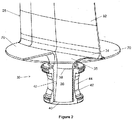
- Figure 3 illustrates a view radially inwardly of the root portion 36. It can be seen that the first cross-sectional area 38 circumscribes an area within the second cross-sectional area 40.
- the area indicated by reference numeral 39 corresponds to the cutaway section in Figure 2 .
- the blade retention arrangement 30 comprises two cheeks 42 and a collar 44.
- the cheeks 42 are described with reference to Figure 4 in which one of the cheeks 42 is shown.
- the cheek 42 comprises a smooth inner surface 46 and a threaded outer surface 48.
- Preferably the threaded outer surface 48 is rolled or otherwise treated for good fatigue strength.
- the inner surface 46 flares from semi-elliptical or semi-oval at its upper edge 50, to match the periphery of the root portion 36 at the first cross-sectional area 38, to semi-circular at its lower edge 52, to match the periphery of the root portion 36 at the second cross-sectional area 40.
- the circumferential length at the lower edge 52 is greater than the circumferential length at the upper edge 50.
- the inner surface 46 of the cheek 42 is arranged to snugly enclose part of the root portion 36 of the propeller blade 28. It will be understood therefore that the upper edge 50, lower edge 52 and profile of the inner surface 46 therebetween will be shaped to match the outer surface of the root portion 36.
- the cheek 42 comprises edge surfaces 54 that define the circumferential extent of the cheek 42.
- the edge surfaces 54 are planar.
- Two cheeks 42 are fitted together with their edge surfaces 54 abutting to form an annular arrangement.
- the edge surfaces 54 of two cheeks 42 may comprise complementary interlock features. Such features may be undulations (radial or axial), pins and recesses, or other arrangements known to the skilled reader.
- the outer surface 48 of the cheek 42 is threaded and semi-annular; that is, it has constant diameter at all radial positions. When two cheeks 42 are fitted together the outer surfaces 48 form a continuous thread around the annular periphery. It will be apparent that the two cheeks 42 are not identical since the threads on the outer surfaces 48 would not match in this case. Additionally, each cheek 42 matches to a different part of the root portion 36 of the propeller blade 28; for example one cheek 42 matches to the shaping due to the leading edge and a second cheek 42 matches to the shaping at the trailing edge of the blade.
- the cheeks 42 are arranged so that their edge surfaces 54 abut at the major axis of the first cross-sectional area 38 of the root portion 36 of the propeller blade 28. This means that one cheek 42 is aligned with the pressure side of the aerofoil portion 32 and the other cheek 42 is aligned with the suction side of the aerofoil portion 32.
- the edge surfaces 54 may abut at the minor axis of the first cross-sectional area 38 or at any intermediate positions between the major and minor axes of the first cross-sectional area 38.
- the two cheeks 42 have equal circumferential extent to avoid the complexities associated with re-entrant assembly.
- edge surfaces 54 may have different circumferential extent so that one pair of edge surfaces 54 abut at one of the axes of the first cross-sectional area 38 and the other pair of edge surfaces 54 abut at the other of the axes or away from both axes.
- the larger cheek 42 may be split to enable simple assembly.
- Other variations of the abutment positions of the edge surfaces 54 will be apparent to the skilled reader.
- the cheek 42 also comprises a flange 56 aligned with the upper edge 50.
- the flange 56 extends outwardly from the outer surface 48 of the cheek 42.
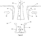
- Figure 5 is an exploded view of part of the propeller blade 28 and of the retention arrangement 30.
- the collar 44 is annular with one closed end 58 which forms the radially innermost part of the retention arrangement 30 when fully assembled.
- the inner surface 60 of the collar 44 is threaded and has constant diameter.
- the outer surface 62 may have any desired profile. For example it may be knurled or finned for grip and grease stirring; or include one or more annular bearing race or have shaping to enable connection to other components such as bearing races, seals and bearing failure catcher features.
- the closed end 58 may include features to connect to a pitch change mechanism.
- the collar 44 comprises an annular flange 64 extending outwardly from the outer surface 62 at the opposite end to the closed end 58.
- the retention arrangement 30 is assembled with the propeller blade 28 in a number of steps. First the two cheeks 42 are pushed towards the root portion 36 of the propeller blade 28 in a direction that is approximately perpendicular to the longitudinal axis L of the propeller blade 28. This is shown by arrows 66. The cheeks 42 are pushed in the direction of arrows 66 until they fit snugly together around the root portion 36 and their edge surfaces 54 abut.
- the collar 44 is screwed onto the outside of the cheeks 42 so that the threads of the inner surface 60 of the collar 44 engage the threads of the outer surfaces 48 of the cheeks 42. This is shown by pigtail arrow 68.
- the collar 44 is screwed until the closed end 58 abuts the lower edge 52 of the cheeks 42.
- the threads may be either handed. However, where the collar 44 is coupled to a pitch change mechanism it is preferable that the threads are so handed as to tighten under the centrifugal turning moment, that is the tendency of the propeller blade 28 to rotate about its longitudinal axis L towards fine pitch, during normal use of the propeller blade 28.
- the non-circular shape of the first cross-sectional area 38 provides efficient centrifugal turning moment torque transfer from the propeller blade 28 to the cheeks 42.
- the collar 44 is screwed onto the outside of the cheeks 42 until the collar flange 64 abuts the cheeks flanges 56. Preferably this is before the closed end 58 of the collar 44 abuts the lower edge 52 of the cheeks 42 to avoid tolerance problems.
- the collar flange 64 is affixed to each cheek flange 56 by adhesive, one or more bolts with optional shear dowels, one or more rivets, welding, straking or any other method understood by the skilled reader.
- the flanges 56, 64 are joined by one or more bolts disassembly is quick and easy when required for inspection, maintenance or other reasons. Apertures in the flange 64 for the bolts may be blind and tapped to avoid creating a grease leakage path from the bearing chamber.
- the flanges 56, 64 give efficient centrifugal turning moment torque transfer from the cheeks 42 to the collar 44.
- the cheeks 42 have greater radial extent than the collar 44.
- the cheeks 42 extend radially for the full longitudinal height of the shank portion 35 of the propeller blade 28.
- the cheeks 42 each comprise part of an integral penny 70. Where the cheeks 42 have equal circumferential extent, each cheek 42 comprises half of the integral penny 70.
- the integral penny 70 resembles a flange with circular periphery. It has an aperture about the axis of symmetry which is shaped to receive the root fillet 34 of the propeller blade 28.
- the integral penny 70 acts to seal against a surrounding casing component whatever pitch the propeller blade 28 is angled at.
- the diameter of the integral penny 70 may be equal to or greater than the chord length of the aerofoil portion 32 of the propeller blade 28.
- the root fillet 34 of the propeller blade 28 forms a smooth gas-washed surface with the integral penny 70.
- the inner surfaces 46 of the cheeks 42 preferably match the shape of the shank portion 35 of the propeller blade 28 between the optional flange 56 and the integral penny 70.
- transitions between the main body of the cheek 42, the flange 56 and the integral penny 70 and between the outer surface 62 of the collar 44 and the flange 64 may each comprise a blend fillet or radius to reduce mechanical stresses.
- the retention arrangement 30 of the present invention is easily assembled but forms a sturdy arrangement once assembled.
- the inner surfaces 46 of the cheeks 42 take the centrifugal loads from the root portion 36 of the propeller blade 28 over a greater projected radially facing area than in the known arrangements so that the load per unit area is reduced. Therefore, thinner and lighter cheeks 42 can be used or a larger root load safety factor achieved for the same size cheeks 42.
- blade pitch torque is transmitted from the closed end 58 of the collar 44, through the cheeks 42 and into the propeller blade 28 via the torque capability of the oval or elliptical first cross-sectional area 38 of the root portion 36.
- the threaded inner surface 60 of the collar 44 and the threaded outer surfaces 48 of the cheeks 42 may be tapered such that the radially outer end of the thread, nearer optional flanges 64, 56, has a larger diameter than the radially inner end of the thread, nearer the closed end 58.
- This pre-compresses the joint between the threads.
- precompression of the joint between the threads can be achieved by providing an entry 'lead' on the thread.
- the threaded outer surfaces 48 of the cheeks 42 and the threaded inner surface 60 of the collar 44 are rolled or otherwise treated to provide good fatigue strength.
- each cheek 42 can have a different shape inner surface 46.
- the cheeks 42 need not comprise the same material as the root portion 36 of the propeller blade 28.
- the cheeks 42 may comprise a material that is optimised for its purposes.
- the cheeks 42 may comprise metal, such as titanium or aluminium, to offer adequate thread shear strength, compressive strength and thermal conductivity.
- the cheeks 42 may comprise metal matrix composite, for example fine silicon carbide particulate reinforced aluminium metal matrix composite, to offer high stiffness combined with low weight and density, thermal expansion that is compatible with the composite root portion 36, and suitable machinability.
- the retention arrangement 30 of the present invention has good shear load transfer from the cheeks 42 into the collar 44 via the threads.
- the outward forces acting on the cheeks 42 are opposed by hoop stresses in the annular collar 44.
- the invention results in greater separation of the bearings on the outer surface 62 of the collar 44 for a given root depth because the flare between the first and second cross-sectional areas 38, 40 that retains the root portion 36 is within the bearing span and not radially inside it. Beneficially this means that more first engine order propeller couple is taken in differential side loading of the bearings instead of differential vertical loading which results in improved bearing life. Also the hub life is improved because there are lower vibratory stresses in the radial retention features for the ball bearing.
- the optional radial extension of the cheeks 42 support the shank portion 35 of the propeller blade 28 against torsion and bending in the event of foreign object damage or other impacts on the propeller blade 28. This minimises energy release by causing preferential failure of the propeller blade 28 above the annulus.
- the optional radial extension to the cheeks 42 and integral penny 70 also protects the retention arrangement 30 and the shank portion 35 of the propeller blade 28 from excessive heat and impact damage.
- the integral penny 70 acts as a heat dump to the free-stream air.
- root portion 36 and inner surfaces 46 of the cheeks 42 may alternatively comprise complementary interlock features.
- they may comprise complementary radial undulations, circumferential undulations or a combination of both.
- such features improve the shear load transfer across this interface, although they complicate the blade root fibre load paths.
- Trim balance weights may be added to the cheek flange 56 to balance the propeller assembly.
- balance weights may be located under bolt heads where such are used to join the collar flange 64 to the cheek flanges 56.
- mid-chord locations on the integral penny 70 can be used for paired balanced counterweights. Since the cheeks 42 are relatively thick in radial alignment with these locations there are good load paths to the pitch bearings. These load paths are also amenable to improvement. For example buttresses can be added to the radially inner surface of the integral penny 70 from the radial extension of the cheeks 42 that match the shank portion 35 of the propeller blade 28 or from the optional flange 56. Alternatively the cheeks 42 can be formed with internal cavities to enhance bending stiffness and strength whilst reducing weight.
- cheeks 42 have been described, more than two cheeks 42 can be provided that abut to form an arrangement having a threaded annular outer surface and a smooth flared inner surface.
- the cheeks 42 may be held together independently of the collar 44 by welding, brazing, bonding, bolts, rivets, complementary interlock features or any other method known to the skilled man.
- the present invention is equally applicable to a 'puller' arrangement in which the propeller(s) is situated at the axially forward part of the engine 10.
- the invention is also applicable with felicity to a turboprop engine, a geared turbofan engine, a marine or industrial gas turbine engine 10, a wind turbine or a tidal turbine.
- the propeller blade 28 and retention arrangement 30 components are likely to comprise a metal such as nickel aluminium bronze.
- the present invention enables the propeller blade 28 to be formed as an integral shape in composite material rather than comprising separate portions that are later joined.
- the propeller blade 28 may be formed by 3D weaving, by the progressive additional of radial (warp) and transverse (weft) tows, or by the progressive thickening of weft tows towards the base of the propeller blade 28.
- bolts to secure the optional flanges 56, 64 together obviates heat damage to the composite propeller blade 28 during manufacture and assembly of the retention arrangement 30. Furthermore, bolted assembly allows more efficient maintenance activity as only those components that need inspection, repair or replacement need to be removed.
- the propeller blade retention arrangement of the present invention may comprise integral seals. These can be located to prevent water ingress, for example from rain ingress into the gas turbine engine 10, and thus reduce the possibility of damage caused by expansion of water on freezing.
- the integral penny 70 may be hollow to reduce weight whilst improving centrifugal load stiffness and strength.
- the integral penny 70 may comprise interlocking with the aperture in the fairing in which it is located in use so that the integral penny 70 acts as a secondary catcher mechanism in the event of bearing failure causing a blade to be released.
- the integral penny 70 can be appropriately strengthened for this task.
- the threaded outer surfaces 48 of the cheeks 42 and the threaded inner surface 60 of the collar 44 may alternatively be replaced by enlarging or otherwise strengthening the collar flange 64 and cheek flanges 56.
- the connection mechanism, for example bolts, between the flanges 56, 64 should be commensurately strengthened.
Landscapes
- Engineering & Computer Science (AREA)
- Aviation & Aerospace Engineering (AREA)
- Structures Of Non-Positive Displacement Pumps (AREA)
Claims (14)
- Agencement de fixation (30) de pale d'hélice comprenant :une pale d'hélice (28) comprenant en séquence radiale une partie profil aérodynamique (32), une partie tige (35) et une partie racine (36) ; la partie racine (36) ayant une première zone transversale (38) près de la partie tige (35) et une seconde zone transversale (40) à l'extrémité distale de la partie profil aérodynamique (32), la seconde zone transversale (40) étant supérieure à la première zone transversale (38) ;deux joues (42) ou plus ayant chacune une surface interne (46) conçue pour venir en butée contre la partie racine (36), une surface externe (48) qui est filetée et des surfaces de bord (54) qui viennent en butée contre une autre des deux joues (42) ou plus ; les deux joues (42) ou plus étant disposées de sorte à entourer la partie racine (36) en butée circonférentielle ;un collier (44) ayant une surface interne filetée conçue pour venir en prise de façon filetée avec les surfaces externes (48) des deux joues (42) ou plus ; etcaractérisé en ce que chaque joue (42) comprend une pièce intégrée (70), la pièce intégrée (70) étant une bride ayant une périphérie externe partiellement circulaire et une périphérie interne conçue pour venir en butée contre la transition entre la partie tige (35) et la partie profil aérodynamique (32) de la pale d'hélice (28).
- Agencement (30) selon la revendication 1, les joues (42) ayant la même étendue circonférentielle.
- Agencement (30) selon la revendication 1 ou 2, la surface interne de chaque joue (42) étant conçue pour compléter la cambrure de la partie profil aérodynamique (32).
- Agencement (30) selon la revendication 3, une première joue (42) étant conçue pour correspondre à un côté pression de la partie profil aérodynamique (32) et une seconde joue (42) étant conçue pour correspondre à un côté aspiration de la partie profil aérodynamique (32).
- Agencement (30) selon l'une quelconque des revendications précédentes, les surfaces internes (46) des deux joues (42) ou plus et la surface externe de la partie racine (36) comprenant chacune des caractéristiques de verrouillage complémentaires ; et les caractéristiques de verrouillage complémentaires comprenant des ondulations radiales ou circonférentielles.
- Agencement (30) selon l'une quelconque des revendications précédentes, les surfaces de bord (54) des deux joues (42) ou plus comprenant des caractéristiques de verrouillage complémentaires ; et les caractéristiques de verrouillage complémentaires comprenant des ondulations, ou des broches et des évidements.
- Agencement (30) selon l'une quelconque des revendications précédentes, le collier (44) étant annulaire et/ou le collier (44) étant accouplé à un mécanisme de modification de pas.
- Agencement (30) selon la revendication 7, la direction de filetage de surface externe étant conçue pour serrer le collier et les joues (42) lors de l'utilisation normale de la pale d'hélice (28).
- Agencement (30) selon la revendication 1, chaque joue (42) comprenant une bride (56) et la bride (56) étant située entre la pièce intégrée (70) et le filetage.
- Agencement (30) selon la revendication 9, le collier (44) comprenant une bride (64) et la bride de joue (56) et la bride de collier (64) étant réunies par : des boulons, des chevilles, des rivets, de l'adhésif, des soudures, des attaches.
- Agencement (30) selon l'une quelconque des revendications précédentes, la première zone transversale (38) ayant une périphérie incurvée allongée et/ou la seconde zone transversale (40) ayant une périphérie circulaire.
- Agencement (30) selon l'une quelconque des revendications précédentes, la partie racine (36) comprenant un matériau composite et/ou le collier (44) comprenant du métal et/ou les joues (42) comprenant : du métal ; un composite à matrice métallique ; un composite à matrice métallique renforcée particulaire.
- Moteur (10) comprenant un ensemble hélice, l'agencement d'hélice comprenant un ensemble d'agencements (30) selon l'une quelconque des revendications 1 à 12.
- Turbine à gaz à hélice (10) comprenant un ensemble hélice, l'agencement d'hélice comprenant un ensemble d'agencements (30) selon l'une quelconque des revendications 1 à 12.
Applications Claiming Priority (1)
| Application Number | Priority Date | Filing Date | Title |
|---|---|---|---|
| GB201307176A GB201307176D0 (en) | 2013-04-22 | 2013-04-22 | Propeller blade retention |
Publications (2)
| Publication Number | Publication Date |
|---|---|
| EP2796367A1 EP2796367A1 (fr) | 2014-10-29 |
| EP2796367B1 true EP2796367B1 (fr) | 2017-09-06 |
Family
ID=48537555
Family Applications (1)
| Application Number | Title | Priority Date | Filing Date |
|---|---|---|---|
| EP14154449.4A Active EP2796367B1 (fr) | 2013-04-22 | 2014-02-10 | Fixation de pale d'hélice |
Country Status (3)
| Country | Link |
|---|---|
| US (1) | US9809299B2 (fr) |
| EP (1) | EP2796367B1 (fr) |
| GB (1) | GB201307176D0 (fr) |
Families Citing this family (8)
| Publication number | Priority date | Publication date | Assignee | Title |
|---|---|---|---|---|
| CN203306224U (zh) * | 2013-05-31 | 2013-11-27 | 深圳市大疆创新科技有限公司 | 螺旋桨及具有该螺旋桨的飞行器 |
| US9849969B2 (en) * | 2015-03-20 | 2017-12-26 | Hamilton Sunstrand Corporation | Lightweight propeller blade with improved retention capacity |
| EP3239040B1 (fr) * | 2016-04-27 | 2020-05-06 | Ratier-Figeac SAS | Pales d'hélice |
| EP3257743B1 (fr) * | 2016-06-14 | 2020-05-20 | Ratier-Figeac SAS | Pales d'hélice |
| EP3323714B1 (fr) * | 2016-11-21 | 2019-07-03 | Ratier-Figeac SAS | Contrepoids d'équilibrage d'hélice |
| CN108757270B (zh) * | 2018-07-10 | 2024-01-09 | 江苏新扬新材料股份有限公司 | 一体化成型复合材料桨叶结构 |
| FR3113647B1 (fr) * | 2020-08-27 | 2023-04-14 | Safran Aircraft Engines | Helice non carenee a pales a calage variable comportant des plate-formes a pertubations reduites |
| US11459089B1 (en) | 2021-04-21 | 2022-10-04 | Hamilton Sundstrand Corporation | Propeller blade having an end plate |
Family Cites Families (19)
| Publication number | Priority date | Publication date | Assignee | Title |
|---|---|---|---|---|
| GB132321A (fr) * | 1900-01-01 | |||
| US1400032A (en) * | 1919-01-16 | 1921-12-13 | Westinghouse Electric & Mfg Co | Self-tightening propeller-hub |
| GB291906A (en) * | 1927-03-19 | 1928-06-14 | Charles Richard Fairey | Improvements in or relating to screw propellers |
| US1885487A (en) * | 1929-03-08 | 1932-11-01 | Squires John | Propeller |
| US1951321A (en) * | 1931-01-03 | 1934-03-13 | Curtiss Aeroplane & Motor Co | Blade retention device |
| US2017505A (en) * | 1933-02-15 | 1935-10-15 | Meon Engineering Corp | Propeller blade mounting for variable pitch propellers |
| US2344876A (en) * | 1942-04-06 | 1944-03-21 | Collins Mason | Reinforced propeller |
| GB1319235A (en) | 1969-07-18 | 1973-06-06 | Dowty Rotol Ltd | Devices of fibrous-reinforced plastics material |
| US3914067A (en) * | 1973-11-30 | 1975-10-21 | Curtiss Wright Corp | Turbine engine and rotor mounting means |
| US3904301A (en) * | 1974-07-24 | 1975-09-09 | Allis Chalmers | Hub locking arrangement |
| US4407635A (en) | 1979-01-08 | 1983-10-04 | Trw Inc. | Aircraft propeller assembly with composite blades |
| US5017092A (en) * | 1989-10-16 | 1991-05-21 | United Technologies Corporation | Rotor blade retention |
| GB2244525B (en) | 1990-04-04 | 1994-09-21 | Dowty Aerospace Gloucester | A propeller hub assembly |
| US6676080B2 (en) * | 2000-07-19 | 2004-01-13 | Aero Composites, Inc. | Composite airfoil assembly |
| GB2443482A (en) | 2006-11-02 | 2008-05-07 | Smiths Group Plc | Propeller blade retention |
| FR2933955B1 (fr) * | 2008-07-18 | 2010-09-03 | Snecma | Dispositif d'attache d'une pale a calage variable |
| GB2475719A (en) | 2009-11-27 | 2011-06-01 | Ge Aviat Systems Ltd | Preloaded propeller blade assembly |
| FR2957051B1 (fr) * | 2010-03-08 | 2012-05-11 | Snecma | Attache de pale recevant un pied de pale dans un brochage |
| CN203306224U (zh) * | 2013-05-31 | 2013-11-27 | 深圳市大疆创新科技有限公司 | 螺旋桨及具有该螺旋桨的飞行器 |
-
2013
- 2013-04-22 GB GB201307176A patent/GB201307176D0/en not_active Ceased
-
2014
- 2014-02-10 EP EP14154449.4A patent/EP2796367B1/fr active Active
- 2014-02-10 US US14/176,646 patent/US9809299B2/en active Active
Non-Patent Citations (1)
| Title |
|---|
| None * |
Also Published As
| Publication number | Publication date |
|---|---|
| US9809299B2 (en) | 2017-11-07 |
| GB201307176D0 (en) | 2013-05-29 |
| US20140314577A1 (en) | 2014-10-23 |
| EP2796367A1 (fr) | 2014-10-29 |
Similar Documents
| Publication | Publication Date | Title |
|---|---|---|
| EP2796367B1 (fr) | Fixation de pale d'hélice | |
| EP2041399B1 (fr) | Entrée de moteur d'avion comprenant une zone de déformation | |
| US8317456B2 (en) | Fan case reinforcement in a gas turbine jet engine | |
| EP2602434B1 (fr) | Système de réduction de charge dynamique | |
| US10851655B2 (en) | Fan | |
| EP2647847A1 (fr) | Structure de fixation d'aubes directrices et soufflante | |
| US10030522B2 (en) | Blade with metallic leading edge and angled shear zones | |
| US20140133975A1 (en) | Double Fan Outlet Guide Vane with Structural Platforms | |
| EP3153680A1 (fr) | Arbre d'entrée de boîte de vitesses de turbine à gaz | |
| CN111878254B (zh) | 气体涡轮引擎 | |
| CA2911943A1 (fr) | Aube guide de sortie tissee en composite | |
| US10717516B2 (en) | Composite propulsor blade support structure and system | |
| US9759129B2 (en) | Removable nosecone for a gas turbine engine | |
| CN108843410A (zh) | 用于喷气发动机的风扇盘以及喷气发动机 | |
| US10677090B2 (en) | Component having co-bonded composite and metal rings and method of assembling same | |
| US9617860B2 (en) | Fan blades for gas turbine engines with reduced stress concentration at leading edge | |
| US20160195015A1 (en) | Gas turbine engine nosecone attachment structure | |
| US11009036B2 (en) | Fan blade having closed metal sheath | |
| EP2672066B1 (fr) | Jonction mécanique pour une aube à matériaux multiple | |
| EP3441562A1 (fr) | Appareil à disque de soufflante | |
| US11060410B2 (en) | Method of forming a protective sheath for an aerofoil component | |
| US11486267B2 (en) | Rolling element device with jointly tiltable raceways | |
| CN111878257B (zh) | 涡轮引擎 | |
| CN111878255B (zh) | 具有双壁核心壳体的气体涡轮引擎 | |
| EP3090134B1 (fr) | Aube de ventilateur avec orifices passants à travers le pied de l'aube |
Legal Events
| Date | Code | Title | Description |
|---|---|---|---|
| PUAI | Public reference made under article 153(3) epc to a published international application that has entered the european phase |
Free format text: ORIGINAL CODE: 0009012 |
|
| 17P | Request for examination filed |
Effective date: 20140210 |
|
| AK | Designated contracting states |
Kind code of ref document: A1 Designated state(s): AL AT BE BG CH CY CZ DE DK EE ES FI FR GB GR HR HU IE IS IT LI LT LU LV MC MK MT NL NO PL PT RO RS SE SI SK SM TR |
|
| AX | Request for extension of the european patent |
Extension state: BA ME |
|
| R17P | Request for examination filed (corrected) |
Effective date: 20150318 |
|
| RBV | Designated contracting states (corrected) |
Designated state(s): AL AT BE BG CH CY CZ DE DK EE ES FI FR GB GR HR HU IE IS IT LI LT LU LV MC MK MT NL NO PL PT RO RS SE SI SK SM TR |
|
| RAP1 | Party data changed (applicant data changed or rights of an application transferred) |
Owner name: ROLLS-ROYCE PLC |
|
| STAA | Information on the status of an ep patent application or granted ep patent |
Free format text: STATUS: EXAMINATION IS IN PROGRESS |
|
| 17Q | First examination report despatched |
Effective date: 20161028 |
|
| GRAP | Despatch of communication of intention to grant a patent |
Free format text: ORIGINAL CODE: EPIDOSNIGR1 |
|
| STAA | Information on the status of an ep patent application or granted ep patent |
Free format text: STATUS: GRANT OF PATENT IS INTENDED |
|
| GRAS | Grant fee paid |
Free format text: ORIGINAL CODE: EPIDOSNIGR3 |
|
| GRAA | (expected) grant |
Free format text: ORIGINAL CODE: 0009210 |
|
| STAA | Information on the status of an ep patent application or granted ep patent |
Free format text: STATUS: THE PATENT HAS BEEN GRANTED |
|
| INTG | Intention to grant announced |
Effective date: 20170720 |
|
| AK | Designated contracting states |
Kind code of ref document: B1 Designated state(s): AL AT BE BG CH CY CZ DE DK EE ES FI FR GB GR HR HU IE IS IT LI LT LU LV MC MK MT NL NO PL PT RO RS SE SI SK SM TR |
|
| REG | Reference to a national code |
Ref country code: GB Ref legal event code: FG4D |
|
| REG | Reference to a national code |
Ref country code: CH Ref legal event code: EP Ref country code: AT Ref legal event code: REF Ref document number: 925579 Country of ref document: AT Kind code of ref document: T Effective date: 20170915 |
|
| REG | Reference to a national code |
Ref country code: IE Ref legal event code: FG4D |
|
| REG | Reference to a national code |
Ref country code: DE Ref legal event code: R096 Ref document number: 602014014034 Country of ref document: DE |
|
| REG | Reference to a national code |
Ref country code: NL Ref legal event code: MP Effective date: 20170906 |
|
| REG | Reference to a national code |
Ref country code: LT Ref legal event code: MG4D |
|
| PG25 | Lapsed in a contracting state [announced via postgrant information from national office to epo] |
Ref country code: LT Free format text: LAPSE BECAUSE OF FAILURE TO SUBMIT A TRANSLATION OF THE DESCRIPTION OR TO PAY THE FEE WITHIN THE PRESCRIBED TIME-LIMIT Effective date: 20170906 Ref country code: SE Free format text: LAPSE BECAUSE OF FAILURE TO SUBMIT A TRANSLATION OF THE DESCRIPTION OR TO PAY THE FEE WITHIN THE PRESCRIBED TIME-LIMIT Effective date: 20170906 Ref country code: HR Free format text: LAPSE BECAUSE OF FAILURE TO SUBMIT A TRANSLATION OF THE DESCRIPTION OR TO PAY THE FEE WITHIN THE PRESCRIBED TIME-LIMIT Effective date: 20170906 Ref country code: FI Free format text: LAPSE BECAUSE OF FAILURE TO SUBMIT A TRANSLATION OF THE DESCRIPTION OR TO PAY THE FEE WITHIN THE PRESCRIBED TIME-LIMIT Effective date: 20170906 Ref country code: NO Free format text: LAPSE BECAUSE OF FAILURE TO SUBMIT A TRANSLATION OF THE DESCRIPTION OR TO PAY THE FEE WITHIN THE PRESCRIBED TIME-LIMIT Effective date: 20171206 |
|
| REG | Reference to a national code |
Ref country code: AT Ref legal event code: MK05 Ref document number: 925579 Country of ref document: AT Kind code of ref document: T Effective date: 20170906 |
|
| REG | Reference to a national code |
Ref country code: FR Ref legal event code: PLFP Year of fee payment: 5 |
|
| PG25 | Lapsed in a contracting state [announced via postgrant information from national office to epo] |
Ref country code: BG Free format text: LAPSE BECAUSE OF FAILURE TO SUBMIT A TRANSLATION OF THE DESCRIPTION OR TO PAY THE FEE WITHIN THE PRESCRIBED TIME-LIMIT Effective date: 20171206 Ref country code: GR Free format text: LAPSE BECAUSE OF FAILURE TO SUBMIT A TRANSLATION OF THE DESCRIPTION OR TO PAY THE FEE WITHIN THE PRESCRIBED TIME-LIMIT Effective date: 20171207 Ref country code: RS Free format text: LAPSE BECAUSE OF FAILURE TO SUBMIT A TRANSLATION OF THE DESCRIPTION OR TO PAY THE FEE WITHIN THE PRESCRIBED TIME-LIMIT Effective date: 20170906 Ref country code: LV Free format text: LAPSE BECAUSE OF FAILURE TO SUBMIT A TRANSLATION OF THE DESCRIPTION OR TO PAY THE FEE WITHIN THE PRESCRIBED TIME-LIMIT Effective date: 20170906 Ref country code: ES Free format text: LAPSE BECAUSE OF FAILURE TO SUBMIT A TRANSLATION OF THE DESCRIPTION OR TO PAY THE FEE WITHIN THE PRESCRIBED TIME-LIMIT Effective date: 20170906 |
|
| PG25 | Lapsed in a contracting state [announced via postgrant information from national office to epo] |
Ref country code: NL Free format text: LAPSE BECAUSE OF FAILURE TO SUBMIT A TRANSLATION OF THE DESCRIPTION OR TO PAY THE FEE WITHIN THE PRESCRIBED TIME-LIMIT Effective date: 20170906 |
|
| PG25 | Lapsed in a contracting state [announced via postgrant information from national office to epo] |
Ref country code: CZ Free format text: LAPSE BECAUSE OF FAILURE TO SUBMIT A TRANSLATION OF THE DESCRIPTION OR TO PAY THE FEE WITHIN THE PRESCRIBED TIME-LIMIT Effective date: 20170906 Ref country code: RO Free format text: LAPSE BECAUSE OF FAILURE TO SUBMIT A TRANSLATION OF THE DESCRIPTION OR TO PAY THE FEE WITHIN THE PRESCRIBED TIME-LIMIT Effective date: 20170906 Ref country code: PL Free format text: LAPSE BECAUSE OF FAILURE TO SUBMIT A TRANSLATION OF THE DESCRIPTION OR TO PAY THE FEE WITHIN THE PRESCRIBED TIME-LIMIT Effective date: 20170906 |
|
| PG25 | Lapsed in a contracting state [announced via postgrant information from national office to epo] |
Ref country code: AT Free format text: LAPSE BECAUSE OF FAILURE TO SUBMIT A TRANSLATION OF THE DESCRIPTION OR TO PAY THE FEE WITHIN THE PRESCRIBED TIME-LIMIT Effective date: 20170906 Ref country code: SK Free format text: LAPSE BECAUSE OF FAILURE TO SUBMIT A TRANSLATION OF THE DESCRIPTION OR TO PAY THE FEE WITHIN THE PRESCRIBED TIME-LIMIT Effective date: 20170906 Ref country code: EE Free format text: LAPSE BECAUSE OF FAILURE TO SUBMIT A TRANSLATION OF THE DESCRIPTION OR TO PAY THE FEE WITHIN THE PRESCRIBED TIME-LIMIT Effective date: 20170906 Ref country code: IT Free format text: LAPSE BECAUSE OF FAILURE TO SUBMIT A TRANSLATION OF THE DESCRIPTION OR TO PAY THE FEE WITHIN THE PRESCRIBED TIME-LIMIT Effective date: 20170906 Ref country code: SM Free format text: LAPSE BECAUSE OF FAILURE TO SUBMIT A TRANSLATION OF THE DESCRIPTION OR TO PAY THE FEE WITHIN THE PRESCRIBED TIME-LIMIT Effective date: 20170906 Ref country code: IS Free format text: LAPSE BECAUSE OF FAILURE TO SUBMIT A TRANSLATION OF THE DESCRIPTION OR TO PAY THE FEE WITHIN THE PRESCRIBED TIME-LIMIT Effective date: 20180106 |
|
| REG | Reference to a national code |
Ref country code: DE Ref legal event code: R097 Ref document number: 602014014034 Country of ref document: DE |
|
| PLBE | No opposition filed within time limit |
Free format text: ORIGINAL CODE: 0009261 |
|
| STAA | Information on the status of an ep patent application or granted ep patent |
Free format text: STATUS: NO OPPOSITION FILED WITHIN TIME LIMIT |
|
| PG25 | Lapsed in a contracting state [announced via postgrant information from national office to epo] |
Ref country code: DK Free format text: LAPSE BECAUSE OF FAILURE TO SUBMIT A TRANSLATION OF THE DESCRIPTION OR TO PAY THE FEE WITHIN THE PRESCRIBED TIME-LIMIT Effective date: 20170906 |
|
| 26N | No opposition filed |
Effective date: 20180607 |
|
| PG25 | Lapsed in a contracting state [announced via postgrant information from national office to epo] |
Ref country code: SI Free format text: LAPSE BECAUSE OF FAILURE TO SUBMIT A TRANSLATION OF THE DESCRIPTION OR TO PAY THE FEE WITHIN THE PRESCRIBED TIME-LIMIT Effective date: 20170906 |
|
| REG | Reference to a national code |
Ref country code: CH Ref legal event code: PL |
|
| PG25 | Lapsed in a contracting state [announced via postgrant information from national office to epo] |
Ref country code: MC Free format text: LAPSE BECAUSE OF FAILURE TO SUBMIT A TRANSLATION OF THE DESCRIPTION OR TO PAY THE FEE WITHIN THE PRESCRIBED TIME-LIMIT Effective date: 20170906 |
|
| REG | Reference to a national code |
Ref country code: IE Ref legal event code: MM4A |
|
| REG | Reference to a national code |
Ref country code: BE Ref legal event code: MM Effective date: 20180228 |
|
| PG25 | Lapsed in a contracting state [announced via postgrant information from national office to epo] |
Ref country code: LU Free format text: LAPSE BECAUSE OF NON-PAYMENT OF DUE FEES Effective date: 20180210 Ref country code: CH Free format text: LAPSE BECAUSE OF NON-PAYMENT OF DUE FEES Effective date: 20180228 Ref country code: LI Free format text: LAPSE BECAUSE OF NON-PAYMENT OF DUE FEES Effective date: 20180228 |
|
| PG25 | Lapsed in a contracting state [announced via postgrant information from national office to epo] |
Ref country code: IE Free format text: LAPSE BECAUSE OF NON-PAYMENT OF DUE FEES Effective date: 20180210 |
|
| PG25 | Lapsed in a contracting state [announced via postgrant information from national office to epo] |
Ref country code: BE Free format text: LAPSE BECAUSE OF NON-PAYMENT OF DUE FEES Effective date: 20180228 |
|
| PG25 | Lapsed in a contracting state [announced via postgrant information from national office to epo] |
Ref country code: MT Free format text: LAPSE BECAUSE OF NON-PAYMENT OF DUE FEES Effective date: 20180210 |
|
| PG25 | Lapsed in a contracting state [announced via postgrant information from national office to epo] |
Ref country code: TR Free format text: LAPSE BECAUSE OF FAILURE TO SUBMIT A TRANSLATION OF THE DESCRIPTION OR TO PAY THE FEE WITHIN THE PRESCRIBED TIME-LIMIT Effective date: 20170906 |
|
| PG25 | Lapsed in a contracting state [announced via postgrant information from national office to epo] |
Ref country code: PT Free format text: LAPSE BECAUSE OF FAILURE TO SUBMIT A TRANSLATION OF THE DESCRIPTION OR TO PAY THE FEE WITHIN THE PRESCRIBED TIME-LIMIT Effective date: 20170906 Ref country code: HU Free format text: LAPSE BECAUSE OF FAILURE TO SUBMIT A TRANSLATION OF THE DESCRIPTION OR TO PAY THE FEE WITHIN THE PRESCRIBED TIME-LIMIT; INVALID AB INITIO Effective date: 20140210 |
|
| PG25 | Lapsed in a contracting state [announced via postgrant information from national office to epo] |
Ref country code: MK Free format text: LAPSE BECAUSE OF NON-PAYMENT OF DUE FEES Effective date: 20170906 Ref country code: CY Free format text: LAPSE BECAUSE OF FAILURE TO SUBMIT A TRANSLATION OF THE DESCRIPTION OR TO PAY THE FEE WITHIN THE PRESCRIBED TIME-LIMIT Effective date: 20170906 |
|
| PG25 | Lapsed in a contracting state [announced via postgrant information from national office to epo] |
Ref country code: AL Free format text: LAPSE BECAUSE OF FAILURE TO SUBMIT A TRANSLATION OF THE DESCRIPTION OR TO PAY THE FEE WITHIN THE PRESCRIBED TIME-LIMIT Effective date: 20170906 |
|
| PGFP | Annual fee paid to national office [announced via postgrant information from national office to epo] |
Ref country code: FR Payment date: 20230223 Year of fee payment: 10 |
|
| P01 | Opt-out of the competence of the unified patent court (upc) registered |
Effective date: 20230528 |
|
| PGFP | Annual fee paid to national office [announced via postgrant information from national office to epo] |
Ref country code: DE Payment date: 20240228 Year of fee payment: 11 Ref country code: GB Payment date: 20240220 Year of fee payment: 11 |