EP2795842B1 - Controller and method for controlling communication services for applications on a physical network - Google Patents
Controller and method for controlling communication services for applications on a physical network Download PDFInfo
- Publication number
- EP2795842B1 EP2795842B1 EP13702409.7A EP13702409A EP2795842B1 EP 2795842 B1 EP2795842 B1 EP 2795842B1 EP 13702409 A EP13702409 A EP 13702409A EP 2795842 B1 EP2795842 B1 EP 2795842B1
- Authority
- EP
- European Patent Office
- Prior art keywords
- network
- applications
- controller
- node
- nodes
- Prior art date
- Legal status (The legal status is an assumption and is not a legal conclusion. Google has not performed a legal analysis and makes no representation as to the accuracy of the status listed.)
- Not-in-force
Links
Images


Classifications
-
- H—ELECTRICITY
- H04—ELECTRIC COMMUNICATION TECHNIQUE
- H04L—TRANSMISSION OF DIGITAL INFORMATION, e.g. TELEGRAPHIC COMMUNICATION
- H04L41/00—Arrangements for maintenance, administration or management of data switching networks, e.g. of packet switching networks
- H04L41/12—Discovery or management of network topologies
-
- H—ELECTRICITY
- H04—ELECTRIC COMMUNICATION TECHNIQUE
- H04L—TRANSMISSION OF DIGITAL INFORMATION, e.g. TELEGRAPHIC COMMUNICATION
- H04L41/00—Arrangements for maintenance, administration or management of data switching networks, e.g. of packet switching networks
- H04L41/14—Network analysis or design
- H04L41/145—Network analysis or design involving simulating, designing, planning or modelling of a network
-
- H—ELECTRICITY
- H04—ELECTRIC COMMUNICATION TECHNIQUE
- H04L—TRANSMISSION OF DIGITAL INFORMATION, e.g. TELEGRAPHIC COMMUNICATION
- H04L41/00—Arrangements for maintenance, administration or management of data switching networks, e.g. of packet switching networks
- H04L41/50—Network service management, e.g. ensuring proper service fulfilment according to agreements
- H04L41/5041—Network service management, e.g. ensuring proper service fulfilment according to agreements characterised by the time relationship between creation and deployment of a service
- H04L41/5054—Automatic deployment of services triggered by the service manager, e.g. service implementation by automatic configuration of network components
-
- H—ELECTRICITY
- H04—ELECTRIC COMMUNICATION TECHNIQUE
- H04L—TRANSMISSION OF DIGITAL INFORMATION, e.g. TELEGRAPHIC COMMUNICATION
- H04L67/00—Network arrangements or protocols for supporting network services or applications
- H04L67/01—Protocols
- H04L67/10—Protocols in which an application is distributed across nodes in the network
-
- G—PHYSICS
- G05—CONTROLLING; REGULATING
- G05B—CONTROL OR REGULATING SYSTEMS IN GENERAL; FUNCTIONAL ELEMENTS OF SUCH SYSTEMS; MONITORING OR TESTING ARRANGEMENTS FOR SUCH SYSTEMS OR ELEMENTS
- G05B2219/00—Program-control systems
- G05B2219/20—Pc systems
- G05B2219/24—Pc safety
- G05B2219/24215—Scada supervisory control and data acquisition
Description
- The present invention relates to a controller and to a method for controlling communication services for applications on a physical network.
- In particular, many networks require a predictable operation with tight timings and high reliability. This is especially true for industrial networks. In this regard, "industrial network" preferably refers to Ethernet/IP-based networks in factory automation, traffic control, machine-to-machine, SCADA (Supervisory control and data acquisition) application areas.
- Current internet and local area network technologies cannot fulfil those requirements. Many conventional technical extensions in the form of industrial communication standards try to solve these issues, e.g. the PROFINET standard. For all of these standards, basically the same steps have to apply. In a first step, the applications have to be planned. In a second step, requirements have to be derived. In a third step, the network has to be planned. In a fourth step, the network has to be rolled out and configured. In a fifth step, the network has to be started for providing the applications.
- One problem with this procedure is the lack of flexibility under tight coupling of the application planning in network configuration and operation. If something changes in the physical network or in one of the applications, at least some of the steps have to be repeated. This may create extra costs due to manual re-planning. Further, this may be error-prone. Furthermore, it may be hard to use non-industrial technologies as a base for products in industrial networks. In particular, the evolution of the standard Internet/LAN technologies is difficult to be integrated within an industrial communication technology like PROFINET. One of these reasons is the required development costs in terms of hardware, like ASICs, such as the case within PROFINET. Any technological improvement in the IEEE standard Ethernet requires large development costs to integrate this extension within PROFINET. Further, this might lead to several generations of the same protocol that cannot interoperate potentially. In addition, the effect of a change on the standard might snow-ball, because PROFINET covers not only networking issues, but also end-devices, middleware and engineering tools that interact with the PROFINET-capable devices and networks. In addition, mixing products from different standards with sometimes very different capabilities in the same network is typically difficult or not possible because conventional planning tools cannot work with heterogeneous standards.
- A further problem is the fact that many applications from different stack holders may compete for the resources and have to be shielded from each other for security and management reasons (multi-tenancy). The share of the network allocated to each application has to be done on-demand and without physically extending the network. The service which the network provides to the applications has to provide guarantees on the one hand, but it also shall enforce restrictions (policy control).
- Further, quality of service, resilience and routing/forwarding has to be managed in the physical network.
- For each above-discussed partial problem, separate technology developments exist in the Internet and local area networks.
- The present partial solutions within the industrial fields may be categorized into the following:
- 1) Use of different physical networks. This approach - while still commonly used - provides no flexibility and creates extra costs for hardware.
- 2) The use of virtualization combined with over-dimensioning of the network by setting up a pre-defined and static series of subnets and LANs around a given application (e.g. a control application of a factory cell). This cellular approach may be also less effective neither in allowing inter-cell communication nor in enabling rational network deployment.
- 3) Industrial extensions to Ethernet protocols to include needs of industrial communication. But this solution lacks flexibility, is not suited for interoperability, and has created specialized niche products that have evolved as stand-alone standards such as Profinet. Those industrial standards typically cannot shield non-industrial applications from each other and must use other means as described in [2] to do so.
- 4) Traffic engineering and QoS (Quality of Service) dimensioning of the network, which is the approach often found in telecommunication networks and used by internet service providers. This allows a certain control over the owned network which is providing communication as a service to multiple tiers. This approach is, however, not as appropriate to the industrial applications, due to the granularity and complexity in defining SLAs (Service level agreements) for each user. This approach is also based on some protocols and specified for larger hardware (such as routers supporting RSVP, MPLS switches, etc.). Thus, existing technologies can here not be used for industrial networks.
- Conventional methods and devices for controlling communication services for applications on a physical network are described in references [1] to [12].
-
US 2011/0258317 A1 describes an application SLA based dynamic, elastic, and adaptive provisioning of network capacity. The document discloses a network resource management (NRM) system for allocating portions of available network capacity to applications, where the available network capacity is treated as a pool of virtual network resources. The NRM system operates by receiving a service level agreement (SLA) that specifies network resources that are requested by an application. The NRM system also receives network topology information regarding features of a physical communication network, which define, in turn, the available network capacity. Based on these inputs, the NRM system allocates a portion of the available network capacity to the application, to produce an SLA assignment. The NRM system then monitors events that may affect the SLA assignment. If such an event is detected, the NRM system can modify the SLA assignment, e.g., by changing or releasing the network resources assigned to the application, etc. - It is one object of the present invention to provide an improved control of communication services for applications on a physical network.
- According to a first aspect, a controller for controlling communication services for a plurality N of applications on a physical network having a plurality M of network nodes providing certain network resources is provided. Each of the N applications is described by at least a set of requirements and optionally a set of traffic patterns and is adapted run on at least two of the M network nodes. The controller comprises a generator and a calculator. The generator is adapted to generate a network model of the physical network including a topology of the physical network and a node model for each of the M network nodes, wherein the node model describes node capabilities and node resources of the network node. The calculator is adapted to calculate N virtual networks for the N applications by mapping each of the set of requirements of the N applications to the provided network model, wherein each of the N calculated virtual networks includes at least two network nodes and a slice of the certain network resources.
- Further, the controller includes M drivers for driving the M network nodes dependent on the N calculated virtual networks and independent on a certain technology used by one of the N network nodes.
- By calculating the virtual networks based on the provided network model, the planning of the physical network and its configuration are separated advantageously. Thus, the efficiency of the physical network may be improved.
- Thus, in the step of calculating the virtual networks it is not necessary to have and use information that identifies how to interface the respective network element. The present controller adds intelligence to optimize and manage the network resources on the fly and not just by means of offline traffic engineering. The result is a managed portioning of the network, with clear service guarantees and associated policies, called "virtual network" or "slice". "Portioning" here refers not only the route data packets can take - as in traditional network virtualisation techniques - but also the share of network resource they can consume. Network resources include bandwidth, schedulers and buffers.
- By means of the M drivers, the controller has the ability to configure a virtual network (slice) along nodes (network elements) with different technologies such as e.g. router, AVB (audio-video-bridging)-capable switch, PROFINET-switch, managed switch. The slice could cross the different network nodes, while guaranteeing at least the minimum guarantee of the simplest node along the path. The different network nodes may be configured on the fly through whatever interface is appropriate. This requires no additional hardware or firmware extension of the network node itself. Thus, the above discussed slice view is an abstraction of the concrete physical network. This slice view is an abstraction layer between the applications view and the view of the physical network itself.
- The physical network includes its connected network elements, like end devices and inner nodes, plus their interconnecting physical links. For example, the physical network is a set of IP and/or OSI layer-2 devices (i.e. routers or switches) interconnected by physical links which can route messages (packets) and can apply constraints on those messages.
- Here, virtual network corresponds to "slice" preferably referring to a logical partition of the physical network connecting several end points and characterized by a class. A slice can exist in several instances of unconnected slices. The class of slice is defined through a distinctive attribute or set of attributes that distinguish different classes, such as security, QoS parameters, importance, and reliability. A slice instance is instantiated by defining the members of the slice in terms of end points, and the characteristics of the network that fulfills the slice class attributes. The slice may be implemented as the virtual network fulfilling the characteristic of the slice class independently of the underlying network or technology used to fulfill those characteristics. A slice instance has an identifier, such as a number.
- "Application" preferably refers to pieces of software or programs distributed across the physical network (distributed service). The software may be considered as a set of end points with the need to communicate with a certain service level over at least one pipe (slice).
- "End point" preferably refers to the leaf of a slice. The end point suggests a distributed nature of the application, which could be peer-to-peer or client-server based, where each application peering end entity is hosted at a different edge of the physical network. Each end point may run as a "virtual end point" (VEP) such as a virtual machine or virtual entity, where a single device can host several VEPs and each VEP belongs to a different slice.
- "Pipe" preferably refers to a connection of two end points. It's a logical connection meaning on the first glance it has nothing to do with routing/forwarding and other properties on the physical layer. A pipe has properties like e.g. minimum or maximum bandwidth and access is controlled.
- "Network model" preferably refers to an abstraction of the concrete physical network using generic nodes but various properties. The generic nodes are preferably described as node models.
- A communication service in this context is the functionality to transport information between endpoints in a network with certain properties. Functionality includes routing respective data forwarding, properties are non-functional issues such as performance or resilience.
- The set of requirements of each application preferably defines the network elements on which the application has to be run and further the paths or path requirements that have to be used.
- Thus, according to implementations, a plurality of network elements, in particular end devices and inner nodes, and/or network architectures may be handled easily.
- According to some implementations, because of the present separation of planning and configuring the physical network, an ability to support multi-tier and remote access to a shared production system is provided, in particular by installing virtual networks on demand. Virtual networks may preferably be called slices, because each of the calculated virtual networks uses a definite slice of the certain network resources of the present physical network.
- In particular compared to conventional virtualization techniques, no communication overhead due to direct node configuration occurs. Thus, there is no need for encapsulation. Moreover, according to some implementations, it is possible to provide holistic QoS and routine approaches targeted at industrial communication networks.
- Further, the calculated N virtual networks may provide a slice application view of the physical network, said slice application view gathering a list of network elements adapted to run at least one application, as well as entry points into the slice. The slice application view may be seen as a graph of an overlay, where each node is a slice end-point, with a given interface describing the expected communication service at each respective interface. This abstract view of expected interfaces is part of the present network model. The interface expected at each end-point of a slice may describe more than QoS parameters such as bandwidth or expected end-to-end delay, but also at some semantics information such as the need for a secure channel, redundant communication, or other requested non-functional qualities of the network. The semantic model may also include the capabilities of the said interface such as e.g. protocols, physical resources, ability to support QoS or policy enforcements. The present abstraction of the physical network, the network model, enables technology independent planning and engineering tools.
- Network elements and applications may be slice system aware meaning they contain components which can interact with the present controller. The present controller may be also called slice manager or slice controller. If devices are not slice system aware, the first slice system aware device in the physical network may terminate the slice system and transparently route all traffic for this device. If an application is not slice system aware, but is placed on a slice system aware device, this device may contain an additional software component which manages slice access on behalf of that application.
- According to an embodiment, the controller includes a configurator for configuring the physical network such that the calculated N virtual networks are fulfilled.
- By means of the configurator, the controller has the ability to configure the physical network on the basis of the calculated virtual networks advantageously. Thus, in sum, the present controller may perform the following tasks: communicating with applications or management stations in order to establish, tear-down or change the virtual networks or to inform if failures or changes occur, automatic management of the available physical resources, and device configurations in order to enable quality-of-service or policing rules.
- According to a further embodiment, the configurator is adapted to configure the physical network by allowing a separate configuration and a separate commissioning for each of the N applications.
- By allowing separate configuration and commissioning steps for each application, a dynamic communication set up and operation is supported advantageously, while shielding each application from each another.
- According to a further embodiment, the calculator is adapted to calculate the N virtual networks such that the N applications are shielded against each other.
- If the applications are shielded against each other, one of the applications may be changed without any impact to the other applications.
- According to a further embodiment, the controller is configured to control the communication services during an operation of the physical network.
- Because the present controller is configured to control the communication services during the operation of the physical network, an application or a network element may be changed while the operation of the physical network is not stopped and a new network model may be calculated and configured to the present physical network. Thus, there is provided an ability to deal with network physical extensions, resource reallocation, for example due to sudden failures or errors, hidden from the application planning and commissioning.
- According to a further embodiment, the node model includes QoS (Quality of Service) capabilities, performance parameters, implementation parameters and/or interfaces of the network node.
- According to a further embodiment, the calculator is configured to map the N sets of requirements of the N applications to the provided network model by using at least one optimization step.
- By optimizing the mapping and therefore the calculation of the virtual networks, the use of the underlined physical network may be improved.
- According to a further embodiment, the controller includes a user interface for planning and configuring the N applications.
- In sum, the present controller may provide an interface for planning tools and applications on the one hand, and interfaces towards the network elements on the other hand. According to a further embodiment, the controller includes a requestor for requesting network information on the network resources from the physical network and node information on the node capabilities and the node resources from at least one of the M network nodes, in particular from all of the M network nodes.
- By means of the requestor, the controller may request the necessary information from the physical network to provide an optimal network model.
- According to a further embodiment, the generator is configured to generate the network model based on the network information and the node information requested by the requestor.
- According to a further embodiment, the physical network is an industrial network, in particular an Ethernet/IP-based industrial network, e.g. PROFINET.
- According to a further embodiment, the M network nodes include a number of end devices which are adapted to run at least one of the N applications and a number of inner nodes which are adapted to forward data packets between at least two end devices.
- According to some implementations, the controller may run slices from backend systems, like cloud, enterprise networks, or remote service providers, deep into the field level crossing multiple network borders, while still protecting critical applications and their communication services.
- The respective means, e.g. the generator, the calculator or the configurator, may be implemented in hardware and/or in software. If said means are implemented in hardware, it may be embodied as a device, e.g. as a computer or as a processor or as a part of a system, e.g. a computer system. If said means are implemented in software it may be embodied as a computer program product, as a function, as a routine, as a program code or as an executable object.
- Any embodiment of the first aspect may be combined with any embodiment of the first aspect to obtain another embodiment of the first aspect.
- According to a second aspect, a method for controlling communication services for a plurality N of applications on a physical network having a plurality M of network nodes providing certain network resources is provided. Each of the N applications is described by a set of requirements and adapted to run on at least two of the M network nodes. In a first step, a network model of the physical network is generated, wherein the network model includes a topology of the physical network and a node model for each of the M network nodes. In particular, the node model describes node capabilities and node resources of the network node. In a second step, N virtual networks for the N applications are calculated by mapping each of the set of requirements of the N applications to the provided network model, wherein each of the N calculated virtual networks includes at least two network nodes and a slice of the certain network resources.
- According to a third aspect, the invention relates to a computer program product comprising a program code for executing the above discussed method for controlling communication services for a plurality N of applications on a physical network when run on at least one computer.
- A computer program product, like a computer program means, may be embodied as a memory card, USB stick, CD-ROM, DVD or as a file which may be downloaded from a server in a network. For example, this may be provided by transferring the respective file with the computer program product from a wireless communication network.
- Further objects, features and advantages of the present invention will become apparent from the subsequent description and depending claims, taking in conjunction with the accompanying drawings, in which:
-
Fig. 1 shows a schematic block diagram of a first embodiment of a controller for controlling communication services for applications on a physical network, -
Fig. 2 shows a schematic block diagram of a second embodiment of a controller for controlling communication services for applications on a physical network, -
Fig. 3 shows two exemplary applications which are to be implemented in the physical network ofFig. 5 , -
Fig. 4 shows a network model of the physical network ofFig. 5 , -
Fig. 5 shows an embodiment of a physical network, -
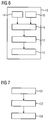
Fig. 6 shows a schematic block diagram of a third embodiment of a controller for controlling communication services for applications on a physical network, and -
Fig. 7 shows an embodiment of a sequence of method steps for controlling communication services for applications on a physical network. - In the Figures, like reference numerals designate like or functionally equivalent elements, unless otherwise indicated.
- In
Fig. 1 , a schematic block diagram of a first embodiment of acontroller 10 for controlling communication services for a plurality N ofapplications physical network 30 having a plurality M of network nodes 41-49 providing certain network resources is depicted. Each of theN applications controller 10 ofFig. 1 is discussed with reference toFigs. 3 to 5 . In this regard,Fig. 5 shows an embodiment of aphysical network 30,Fig. 4 anetwork model 50 of thephysical network 30 ofFig. 5, and Fig. 3 twoexemplary applications Fig. 5 . - With respect to
Fig. 3 , and without loss of generality, N=2 in this example. Further, with reference toFigs. 4 and 5 , M=9 without loss of generality. -
Fig. 3 shows twoapplications first application 21 has four end devices 41-44 between which data packets are to be transferred. In contrast, thesecond application 22 has only twoend devices Fig. 5 , thephysical network 30 has nine network elements 41-49. Said nine network elements 41-49 include four end devices 41-44 which are adapted to run at least one of theapplications - Coming back to the
controller 10 ofFig. 1 , saidcontroller 10 comprises agenerator 11 and acalculator 12. Thegenerator 11 is adapted to generate thenetwork model 50 according toFig. 4 of thephysical network 30 ofFig. 5 . The generatednetwork model 50 includes atopology 60 of thephysical network 30 and a node model 71-79 for each of the nine network nodes 41-49 of thephysical network 30 ofFig. 5 . The respective network model 71-79 describes node capabilities and node resources of the respective network node 41-49. In other words, for each of the network nodes 41-49 ofFig. 5 one respective node model 71-79 is generated. - The
calculator 12 of thecontroller 10 is adapted to calculate two (N=2)virtual networks applications applications network model 50. - Therein, each of the two calculated
virtual networks physical network 30. - Particularly, the
calculator 12 is configured to map the two sets of requirements of the twoapplications network model 50 by applying at least one optimization step. Further, thecalculator 12 may calculate the twovirtual networks applications - The
controller 10 is further configured to control the communication services during an operation of thephysical network 30. That means that, for example, oneapplication controller 10 may generate anew network model 50 and may calculate newvirtual networks -
Fig. 2 shows a second embodiment of acontroller 10 for controlling communication services for a plurality N ofapplications physical network 30 having a plurality M of network nodes 41-49 providing certain network resources. Said second embodiment of thecontroller 10 ofFig. 2 is based on the first embodiment ofFig. 1 . Additionally toFig. 1 , thecontroller 10 ofFig. 2 includes aconfigurator 13 which is adapted to configure thephysical network 30 such that the calculated twovirtual networks physical network 30, in particular its network elements 41-49, is adapted to provide said calculatedvirtual networks configurator 13 may be adapted to configure thephysical network 30 by allowing a separate configuration and a separate commissioning for each of the twoapplications - Moreover, in
Fig. 6 , a third embodiment of acontroller 10 is depicted which is based on the second embodiment ofFig. 2 . - The
controller 10 ofFig. 6 additionally comprises auser interface 14 and a requestor 15. Further, theconfigurator 13 ofFig. 6 comprises a number M of drivers. - By means of the
user interface 14, a user may plan and configure theN applications - The M drivers are configured to drive the M network nodes 41-49 dependent on the N calculated
virtual networks drivers 13, any technology can be used for network nodes 41-43, which has no impact on calculating thevirtual networks - Further, the requestor 15 is adapted to request network information on the network resources from the
physical network 30 and node information on the node capabilities and the node resources from the network nodes 41-49. In this third embodiment, thegenerator 30 may be configured to generate thenetwork model 50 based on the network information and the node information as requested by the requestor 15. - In
Fig. 7 , a method for controlling communication services for a plurality N ofapplications physical network 30 having a plurality M of network nodes 41-49 providing certain network resources is depicted. Each of theN applications - The method of
Fig. 7 includes the following steps 101-103: - In
step 101, anetwork model 50 of thephysical network 30 is generated. Thenetwork model 50 includes atopology 60 of thephysical network 30 and a node model 71-79 for each of the M network nodes 41-49 (seeFigs. 3-5 ). In this regard, the node model 71-79 describes node capabilities and node resources of the network node 41-49. - In
step 102, Nvirtual networks N applications N applications network model 50. Each of the N calculatedvirtual networks - In
step 103, thephysical network 30 is configured such that the calculated Nvirtual networks - In particular, above steps 101-103 may be executed during the operation of the
physical network 30. - The following example may illustrate the present invention. In this example, the controller may also be called slice manager and the respective virtual network may be called slice.
- In the present example, the following prerequisites are fulfilled:
- 1. The slice manager knows the network topology. This can be assured by means of a prepared configuration or by means of automatic discovery.
- 2. All devices (network elements) which have to be controlled by the slice manager must be known; if the respective information is not given in 1., the devices register with the slice manager. The information for a device includes QoS capabilities, performance parameters, interfaces and eventually more implementation specific information.
- 3. For each desired slice (VN) a description exists which includes a list of end devices, applications on that end devices (for slice system aware devices only), QoS requirements, and some notion of importance and/or resilience requirements. Optionally a specification of the traffic assumed for this slice may exist to allow better optimizations. Another optional description may contain security related issues, i.e. firewall rules, access rules, and upper limits of bandwidth usage.
- Then the following steps have to be performed to create and use a slice:
- 1. Some instance triggers slice creation by sending a message to the slice manager containing a slice description as described in the prerequisites.
- 2. The slice manager starts some algorithm to find an optimal mapping of the slice requirements to the actual network taking device capabilities, available resources, topology and slice requirements and assumed slice traffic into account. If resource conflicts occur, those may be resolved using the importance properties. The mapping process includes also the identification of "inner" slice nodes, which is, finding an optimal path between the slice ends.
- 3. The slice manager now configures all nodes participating in that slice as well as all inner nodes to perform data forwarding with the desired QoS constraints.
- 4. If end devices are slice aware, they will create a virtual network interface used as a slice entry by the respective applications.
- Although the present invention has been described in accordance with preferred embodiments, it is obvious for a person skilled in the art that modifications are possible in all embodiments.
-
- [1] M. J. Teener, R. Boatright, M. X. Mora, Standards-based Audio networks using IEEE 802.1 AVB, Whitepaper, Broadcom Inc, 2008, AVBforAES-200810.pdf
- [2] Design Patterns: Elements of Reusable Object-Oriented Software by Erich Gamma, Richard Helm, Ralph Johnson, and John Vlissides, ISBN 978-0201633610 , ISBN 0-201-63361-2, Addison Wesley Professional, November 10, 1994
- [3] White Paper, Network Services Virtualization, Cisco Inc., 2009, http://www.cisco.com/en/US/prod/collateral/switches/ps5718/ps 4324/white_paper_c11-531522.pdf
- [4] M. Seaman, A Multiple VLAN Registration Protocol (MVRP), IEEE, May 2004, http://ieee802.org/1/files/public/docs2004/MVRP-Introduction-030.pdf
- [5] White Paper, IEEE 802.1ak - MVRP and MRP, Cisco Inc., March 2009, IEEE802.1ak - MVRP and MRP
- [6] P. Frieden, VLANs on Linux, Linux Journal, March 2004, http://www.linuxjournal.com/article/7268?page=0,2
- [7] Eric W. Biedermann, Multiple Instances of the Global Linux Namespaces, proceedings of the Linux Symposium, Volume One, July 19th-22nd, 2006, Ottawa, Ontario, Canada
- [8] W. Maurer, Professional Linux® Kernel Architecture, Wiley Publishing, Inc., USA, 2008, ISBN: 978-0-470-34343-2,
- [9] S. Shenker, C. Partridge, R. Guerin, "Specification of Guaranteed Quality of Service", RFC 2212, Sept. 1997
- [10] L. Westberg, A. Csaszar, G. Karagannis, A. Marquetant, D. Partain, O. Pop, V. Rexhepi, R. Szabo, A. Takacs, "Resource management in DiffServ (RMD) - A Functionality and Performance Behaviour Overview", Proceedings of the 7thIFIP/IEEE International Workshop on Protocols for High Speed Networks, Springer-Verlag London, UK, 2002
- [11] N. McKeown, T. Anderson, H. Balakrishnan, G. Parulkar, L. Peterson, J. Rexford, S. Shenker, J. Turner, Open-Flow: Enabling Innovation in Campus Networks, White Paper, March 2008, www.openflow.org/
- [12] The GENI Project Office, The GENI System Overview, Document ID: GENISE-SY-SO-02.0, September 29, 2008, Cambridge, US, www.geni.net
Claims (14)
- A controller (10) for controlling communication services for a plurality N of applications (21,22) on a physical network (30) having a plurality M of network nodes (41-49) providing certain network resources, wherein each of the N applications (21,22) is described by a set of requirements and is adapted to run on at least two of the M network nodes (41-48), the controller (10) comprising:a generator (11) for generating a network model (50) of the physical network (30) including a topology (60) of the physical network (30) and a node model (71-79) for each of the M network nodes (41-49), wherein the node model (71-79) describes node capabilities and node resources of the network node (41-49),a calculator (12) for calculating N virtual networks (81,82) for the N applications (21,22) by mapping each of the set of requirements of the N applications (21,22) to the provided network model (50), wherein each of the N calculated virtual networks (81, 82) includes at least two network nodes (41-49) and a slice of the certain network resources, andM drivers (13) for driving the M network nodes (41-49) dependent on the N calculated virtual networks (81, 82) and independent on a certain technology used by one of the N network nodes (41-49).
- The controller of claim 1, comprising:a configurator (13) for configuring the physical network (30) such that the calculated N virtual networks (81,82) are fulfilled.
- The controller of claim 2,
wherein the configurator (13) is adapted to configure the physical network (30) by allowing a separate configuration and a separate commissioning for each of the N applications (21, 22). - The controller one of claims 1 to 3,
wherein the calculator (12) is adapted to calculate the N virtual networks (81, 82) such that the N applications (21, 22) are shielded against each other. - The controller of claim 4,
wherein the controller (10) is configured to control the communication services during an operation of the physical network (30). - The controller of one of claims 1 to 5,
wherein the node model (71-79) includes QoS capabilities, performance parameters, implementation parameters and/or interfaces of the network node. - The controller of one of claims 1 to 6,
wherein the calculator (12) is configured to map the N sets of requirements of the N applications (21, 22) to the provided network model (50) by using at least one optimization step. - The controller of one of claims 1 to 7, comprising:a user interface (14) for planning and configuring the N applications (21, 22).
- The controller of one of claims 1 to 8, comprising:a requestor (15) for requesting network information on the network resources from the physical network (30) and node information on the node capabilities and the node resources from at least one of the M network nodes (41-49), and particular from all of the M network nodes (41-49).
- The controller of claim 9,
wherein the generator (11) is configured to generate the network model (50) based on the network information and the node information requested by the requestor (15). - The controller of one of claims 1 to 10,
wherein the physical network (30) is an industrial network, in particular an Ethernet/IP-based industrial network, e.g. PROFINET. - The controller of one of claims 1 to 10,
wherein the M network nodes (41-49) include a number of end devices (41-44) which are adapted to run at least one of the N applications (21,22) and a number of inner nodes (45-49) which are adapted to forward data packets between at least two end devices (41-44). - A method for controlling communication services for a plurality N of applications (21, 22) on a physical network (30) having a plurality M of network nodes (41-49) providing certain network resources, wherein each of the N applications (21, 22) is described by a set of requirements and is adapted to run on at least two of the M network nodes (41-49), the method comprising:generating (101) a network model (50) of the physical network (30) including a topology of the physical network (30) and a node model (71-79) for each of the M network nodes (41-49), wherein the node model (71-79) describes node capabilities and node resources of the network node (41-49), andcalculating (102) N virtual networks for the N applications by mapping each of the set of requirements of the N applications (21,22) to the provided network model (50), wherein each of the N calculated virtual networks (81,82) includes at least two network nodes (41-49) and a slice of the certain network resources,wherein the M network nodes (41-49) are driven by M drivers (13) dependent on the N calculated virtual networks (81, 82) and independent on a certain technology used by one of the N network nodes (41-49).
- A computer program product comprising a program code for executing the method of claim 13 for controlling communication services for a plurality N of applications (21, 22) on a physical network (30) when run on at least one computer.
Priority Applications (1)
| Application Number | Priority Date | Filing Date | Title |
|---|---|---|---|
| EP13702409.7A EP2795842B1 (en) | 2012-01-26 | 2013-01-25 | Controller and method for controlling communication services for applications on a physical network |
Applications Claiming Priority (3)
| Application Number | Priority Date | Filing Date | Title |
|---|---|---|---|
| EP12000488 | 2012-01-26 | ||
| EP13702409.7A EP2795842B1 (en) | 2012-01-26 | 2013-01-25 | Controller and method for controlling communication services for applications on a physical network |
| PCT/EP2013/051401 WO2013110742A1 (en) | 2012-01-26 | 2013-01-25 | Controller and method for controlling communication services for applications on a physical network |
Publications (2)
| Publication Number | Publication Date |
|---|---|
| EP2795842A1 EP2795842A1 (en) | 2014-10-29 |
| EP2795842B1 true EP2795842B1 (en) | 2016-08-24 |
Family
ID=47633031
Family Applications (1)
| Application Number | Title | Priority Date | Filing Date |
|---|---|---|---|
| EP13702409.7A Not-in-force EP2795842B1 (en) | 2012-01-26 | 2013-01-25 | Controller and method for controlling communication services for applications on a physical network |
Country Status (5)
| Country | Link |
|---|---|
| US (1) | US10389595B2 (en) |
| EP (1) | EP2795842B1 (en) |
| CN (1) | CN104081719B (en) |
| CA (1) | CA2862585C (en) |
| WO (1) | WO2013110742A1 (en) |
Cited By (8)
| Publication number | Priority date | Publication date | Assignee | Title |
|---|---|---|---|---|
| WO2018141357A1 (en) | 2017-01-31 | 2018-08-09 | Siemens Aktiengesellschaft | Method for operating an industrial automation system communication network comprising a plurality of communication devices, and control unit |
| WO2018177537A1 (en) | 2017-03-31 | 2018-10-04 | Siemens Aktiengesellschaft | Method for operating an industrial automation system communication network comprising a plurality of communication devices, and control unit |
| WO2018196992A1 (en) | 2017-04-28 | 2018-11-01 | Siemens Aktiengesellschaft | Method for operating an industrial automation system communication network comprising a plurality of communication devices, and control unit |
| WO2019001729A1 (en) | 2017-06-30 | 2019-01-03 | Siemens Aktiengesellschaft | Method for operating an industrial automation system communication network comprising a plurality of communication devices, and control unit |
| EP3435180A1 (en) | 2017-07-28 | 2019-01-30 | Siemens Aktiengesellschaft | Method for operating a communication network comprising multiple communication devices of an industrial automation system and control unit |
| EP3461081A1 (en) | 2017-09-22 | 2019-03-27 | Siemens Aktiengesellschaft | Method for operating a communication network comprising multiple communication devices of an industrial automation system, control unit and communication device |
| EP3462673A1 (en) | 2017-09-29 | 2019-04-03 | Siemens Aktiengesellschaft | Method for operating a communication network of an industrial automation system and control device |
| EP3499798A1 (en) | 2017-12-15 | 2019-06-19 | Siemens Aktiengesellschaft | Method for transmitting data within an industrial communication network and network controller |
Families Citing this family (36)
| Publication number | Priority date | Publication date | Assignee | Title |
|---|---|---|---|---|
| US8837491B2 (en) | 2008-05-27 | 2014-09-16 | Glue Networks | Regional virtual VPN |
| US8743885B2 (en) | 2011-05-03 | 2014-06-03 | Cisco Technology, Inc. | Mobile service routing in a network environment |
| US9760528B1 (en) | 2013-03-14 | 2017-09-12 | Glue Networks, Inc. | Methods and systems for creating a network |
| US9928082B1 (en) | 2013-03-19 | 2018-03-27 | Gluware, Inc. | Methods and systems for remote device configuration |
| US9973429B2 (en) * | 2013-04-05 | 2018-05-15 | Futurewei Technologies, Inc. | Software defined networking (SDN) controller orchestration and network virtualization for data center interconnection |
| US9203765B2 (en) * | 2013-08-30 | 2015-12-01 | Cisco Technology, Inc. | Flow based network service insertion using a service chain identifier |
| US9479443B2 (en) | 2014-05-16 | 2016-10-25 | Cisco Technology, Inc. | System and method for transporting information to services in a network environment |
| US9379931B2 (en) | 2014-05-16 | 2016-06-28 | Cisco Technology, Inc. | System and method for transporting information to services in a network environment |
| DE102014219472A1 (en) * | 2014-09-25 | 2016-03-31 | Siemens Aktiengesellschaft | Method for transmitting data, network nodes and network |
| US10417025B2 (en) | 2014-11-18 | 2019-09-17 | Cisco Technology, Inc. | System and method to chain distributed applications in a network environment |
| US9785412B1 (en) * | 2015-02-27 | 2017-10-10 | Glue Networks, Inc. | Methods and systems for object-oriented modeling of networks |
| US9762402B2 (en) | 2015-05-20 | 2017-09-12 | Cisco Technology, Inc. | System and method to facilitate the assignment of service functions for service chains in a network environment |
| US9929945B2 (en) | 2015-07-14 | 2018-03-27 | Microsoft Technology Licensing, Llc | Highly available service chains for network services |
| CN106375987B (en) * | 2015-07-22 | 2021-08-20 | 中兴通讯股份有限公司 | Network slice selection method and system |
| US10644955B2 (en) * | 2015-08-21 | 2020-05-05 | Huawei Technologies Co., Ltd. | Method and apparatus for network slicing |
| CN106550410B (en) * | 2015-09-17 | 2020-07-07 | 华为技术有限公司 | Communication control method, controller, user equipment and related device |
| US9686316B2 (en) * | 2015-09-25 | 2017-06-20 | Cisco Technology, Inc. | Layer-2 security for industrial automation by snooping discovery and configuration messages |
| JP6382790B2 (en) | 2015-12-28 | 2018-08-29 | ファナック株式会社 | Manufacturing data processing system including a plurality of manufacturing apparatuses |
| US10156841B2 (en) | 2015-12-31 | 2018-12-18 | General Electric Company | Identity management and device enrollment in a cloud service |
| US11044203B2 (en) | 2016-01-19 | 2021-06-22 | Cisco Technology, Inc. | System and method for hosting mobile packet core and value-added services using a software defined network and service chains |
| CN110572838B (en) * | 2016-03-03 | 2020-08-07 | 华为技术有限公司 | Communication method, terminal equipment and network side equipment |
| CN107580360A (en) * | 2016-07-04 | 2018-01-12 | 中国移动通信有限公司研究院 | A kind of network is cut into slices method, equipment and the network architecture of selection |
| CN112291832A (en) | 2016-08-22 | 2021-01-29 | 华为技术有限公司 | Method and device for selecting network slices |
| CN107872339B (en) * | 2016-09-27 | 2022-11-18 | 中兴通讯股份有限公司 | Operation and maintenance implementation method and device in virtual network and virtual network system |
| US11323335B2 (en) | 2016-10-18 | 2022-05-03 | Telefonaktiebolaget Lm Ericsson (Publ) | SLA handling in network slices |
| BR112019008694A2 (en) | 2016-10-31 | 2019-10-08 | Huawei Tech Co Ltd | network slice management unit and system management method |
| US10819653B2 (en) | 2016-12-29 | 2020-10-27 | Siemens Aktiengesellschaft | Control unit and method for operating an industrial automation system communication network comprising a plurality of communication devices |
| WO2018176391A1 (en) * | 2017-03-31 | 2018-10-04 | Zte Corporation | Method and apparatus for session management function selection |
| US10693738B2 (en) | 2017-05-31 | 2020-06-23 | Cisco Technology, Inc. | Generating device-level logical models for a network |
| WO2019083843A1 (en) * | 2017-10-23 | 2019-05-02 | Nokia Solutions And Networks Oy | Network slice configuration |
| DE102018207995A1 (en) * | 2018-05-22 | 2019-11-28 | Siemens Aktiengesellschaft | Multi-tenant connector and method for multi-tenant connection of different network domains |
| CN110912795B (en) * | 2018-09-14 | 2022-04-15 | 中兴通讯股份有限公司 | Transmission control method, node, network system and storage medium |
| US11252042B2 (en) * | 2019-04-12 | 2022-02-15 | Huawei Technologies Co., Ltd. | Systems and methods for communication network customization |
| CN111585784B (en) * | 2020-03-23 | 2023-08-15 | 北京中电飞华通信有限公司 | Network slice deployment method and device |
| CN112578755A (en) * | 2020-12-17 | 2021-03-30 | 上海通群科技有限公司 | Programmable intelligent controller and application system based on programmable intelligent controller |
| US11870647B1 (en) * | 2021-09-01 | 2024-01-09 | Amazon Technologies, Inc. | Mapping on-premise network nodes to cloud network nodes |
Family Cites Families (11)
| Publication number | Priority date | Publication date | Assignee | Title |
|---|---|---|---|---|
| US6973477B1 (en) * | 1995-05-19 | 2005-12-06 | Cyberfone Technologies, Inc. | System for securely communicating amongst client computer systems |
| US7310673B2 (en) * | 2001-12-21 | 2007-12-18 | Hewlett-Packard Development Company, L.P. | Network resource assignment system and method |
| US20060031444A1 (en) * | 2004-05-28 | 2006-02-09 | Drew Julie W | Method for assigning network resources to applications for optimizing performance goals |
| EP1624614B1 (en) * | 2004-08-02 | 2008-01-02 | Siemens Aktiengesellschaft | Automatic planning of network configurations |
| US7409478B2 (en) * | 2006-04-21 | 2008-08-05 | At&T Delaware Intellectual Property Inc. | Peripheral hardware devices providing multiple interfaces and related systems and methods |
| US7958184B2 (en) * | 2008-03-04 | 2011-06-07 | International Business Machines Corporation | Network virtualization in a multi-node system with multiple networks |
| US9106540B2 (en) | 2009-03-30 | 2015-08-11 | Amazon Technologies, Inc. | Providing logical networking functionality for managed computer networks |
| FR2948248B1 (en) | 2009-07-16 | 2011-08-19 | Univ Paris Curie | METHOD AND SYSTEM FOR STOLEN DEPLOYMENT AND ON REQUEST AT LEAST ONE VIRTUAL NETWORK. |
| BR112012013678A2 (en) * | 2009-12-15 | 2017-10-10 | Telefonica Sa | "Method for Distributing Routing Information for Redundant Connections" |
| US20110258317A1 (en) * | 2010-04-19 | 2011-10-20 | Microsoft Corporation | Application sla based dynamic, elastic, and adaptive provisioning of network capacity |
| US8965746B2 (en) * | 2012-01-05 | 2015-02-24 | General Electric Company | System and method for validating an electrical network model |
-
2013
- 2013-01-25 CA CA2862585A patent/CA2862585C/en not_active Expired - Fee Related
- 2013-01-25 US US14/373,254 patent/US10389595B2/en not_active Expired - Fee Related
- 2013-01-25 WO PCT/EP2013/051401 patent/WO2013110742A1/en active Application Filing
- 2013-01-25 EP EP13702409.7A patent/EP2795842B1/en not_active Not-in-force
- 2013-01-25 CN CN201380006828.1A patent/CN104081719B/en not_active Expired - Fee Related
Cited By (9)
| Publication number | Priority date | Publication date | Assignee | Title |
|---|---|---|---|---|
| WO2018141357A1 (en) | 2017-01-31 | 2018-08-09 | Siemens Aktiengesellschaft | Method for operating an industrial automation system communication network comprising a plurality of communication devices, and control unit |
| WO2018177537A1 (en) | 2017-03-31 | 2018-10-04 | Siemens Aktiengesellschaft | Method for operating an industrial automation system communication network comprising a plurality of communication devices, and control unit |
| WO2018196992A1 (en) | 2017-04-28 | 2018-11-01 | Siemens Aktiengesellschaft | Method for operating an industrial automation system communication network comprising a plurality of communication devices, and control unit |
| WO2019001729A1 (en) | 2017-06-30 | 2019-01-03 | Siemens Aktiengesellschaft | Method for operating an industrial automation system communication network comprising a plurality of communication devices, and control unit |
| EP3435180A1 (en) | 2017-07-28 | 2019-01-30 | Siemens Aktiengesellschaft | Method for operating a communication network comprising multiple communication devices of an industrial automation system and control unit |
| WO2019020500A1 (en) | 2017-07-28 | 2019-01-31 | Siemens Aktiengesellschaft | Method for operating an industrial automation system communication network comprising a plurality of communication devices, and control unit |
| EP3461081A1 (en) | 2017-09-22 | 2019-03-27 | Siemens Aktiengesellschaft | Method for operating a communication network comprising multiple communication devices of an industrial automation system, control unit and communication device |
| EP3462673A1 (en) | 2017-09-29 | 2019-04-03 | Siemens Aktiengesellschaft | Method for operating a communication network of an industrial automation system and control device |
| EP3499798A1 (en) | 2017-12-15 | 2019-06-19 | Siemens Aktiengesellschaft | Method for transmitting data within an industrial communication network and network controller |
Also Published As
| Publication number | Publication date |
|---|---|
| CN104081719B (en) | 2017-12-15 |
| CN104081719A (en) | 2014-10-01 |
| CA2862585C (en) | 2020-06-09 |
| WO2013110742A1 (en) | 2013-08-01 |
| CA2862585A1 (en) | 2013-08-01 |
| US20140372617A1 (en) | 2014-12-18 |
| US10389595B2 (en) | 2019-08-20 |
| EP2795842A1 (en) | 2014-10-29 |
Similar Documents
| Publication | Publication Date | Title |
|---|---|---|
| EP2795842B1 (en) | Controller and method for controlling communication services for applications on a physical network | |
| Molina et al. | Software-defined networking in cyber-physical systems: A survey | |
| US9819540B1 (en) | Software defined network controller | |
| US10212088B2 (en) | Tactical traffic engineering based on segment routing policies | |
| CN107409089B (en) | Method implemented in network engine and virtual network function controller | |
| EP2800308B1 (en) | Tunnel failover | |
| EP3262793B1 (en) | System and method for automatically detecting and configuring server uplink network interface | |
| CN115380514A (en) | Automated deployment of network elements for heterogeneous computing elements | |
| CN112398676B (en) | Vendor-independent profile-based modeling of service access endpoints in a multi-tenant environment | |
| US11528190B2 (en) | Configuration data migration for distributed micro service-based network applications | |
| EP4020924A1 (en) | Edge controller with network performance parameter support | |
| US8346899B2 (en) | Method and system for NIC-centric hyper-channel distributed network management | |
| CN112491707B (en) | Method and device for determining forwarding path | |
| Mohammed et al. | SDN controller for network-aware adaptive orchestration in dynamic service chaining | |
| da Silva Coelho et al. | On the impact of novel function mappings, sharing policies, and split settings in network slice design | |
| Mendiola et al. | Enhancing network resources utilization and resiliency in multi-domain bandwidth on demand service provisioning using SDN | |
| CN113193975B (en) | Controller device, method and computer readable storage medium | |
| Dasarathy et al. | Network qos assurance in a multi-layer adaptive resource management scheme for mission-critical applications using the corba middleware framework | |
| Matias et al. | The EHU-OEF: an OpenFlow-based layer-2 experimental facility | |
| CN114365454A (en) | Distribution of stateless security functions | |
| EP3725044B1 (en) | Actn virtual network augmentation for resource sharing | |
| Jansen et al. | Middleware for coordinating a tactical router with SOA services | |
| Lee et al. | Extended ACTN Architecture to Enable End-To-End 5G Transport Service Assurance | |
| Derakhshan et al. | Enabling cloud connectivity using SDN and NFV technologies | |
| Borcoci | Software defined networking and architectures |
Legal Events
| Date | Code | Title | Description |
|---|---|---|---|
| PUAI | Public reference made under article 153(3) epc to a published international application that has entered the european phase |
Free format text: ORIGINAL CODE: 0009012 |
|
| 17P | Request for examination filed |
Effective date: 20140714 |
|
| AK | Designated contracting states |
Kind code of ref document: A1 Designated state(s): AL AT BE BG CH CY CZ DE DK EE ES FI FR GB GR HR HU IE IS IT LI LT LU LV MC MK MT NL NO PL PT RO RS SE SI SK SM TR |
|
| DAX | Request for extension of the european patent (deleted) | ||
| REG | Reference to a national code |
Ref country code: DE Ref legal event code: R079 Ref document number: 602013010592 Country of ref document: DE Free format text: PREVIOUS MAIN CLASS: H04L0012240000 Ipc: H04L0029080000 |
|
| RIC1 | Information provided on ipc code assigned before grant |
Ipc: H04L 12/24 20060101ALI20160126BHEP Ipc: H04L 29/08 20060101AFI20160126BHEP |
|
| GRAP | Despatch of communication of intention to grant a patent |
Free format text: ORIGINAL CODE: EPIDOSNIGR1 |
|
| INTG | Intention to grant announced |
Effective date: 20160309 |
|
| GRAS | Grant fee paid |
Free format text: ORIGINAL CODE: EPIDOSNIGR3 |
|
| GRAA | (expected) grant |
Free format text: ORIGINAL CODE: 0009210 |
|
| GRAT | Correction requested after decision to grant or after decision to maintain patent in amended form |
Free format text: ORIGINAL CODE: EPIDOSNCDEC |
|
| AK | Designated contracting states |
Kind code of ref document: B1 Designated state(s): AL AT BE BG CH CY CZ DE DK EE ES FI FR GB GR HR HU IE IS IT LI LT LU LV MC MK MT NL NO PL PT RO RS SE SI SK SM TR |
|
| REG | Reference to a national code |
Ref country code: GB Ref legal event code: FG4D |
|
| REG | Reference to a national code |
Ref country code: CH Ref legal event code: EP |
|
| REG | Reference to a national code |
Ref country code: AT Ref legal event code: REF Ref document number: 823965 Country of ref document: AT Kind code of ref document: T Effective date: 20160915 |
|
| REG | Reference to a national code |
Ref country code: IE Ref legal event code: FG4D |
|
| REG | Reference to a national code |
Ref country code: DE Ref legal event code: R096 Ref document number: 602013010592 Country of ref document: DE |
|
| REG | Reference to a national code |
Ref country code: LT Ref legal event code: MG4D |
|
| REG | Reference to a national code |
Ref country code: NL Ref legal event code: MP Effective date: 20160824 |
|
| REG | Reference to a national code |
Ref country code: AT Ref legal event code: MK05 Ref document number: 823965 Country of ref document: AT Kind code of ref document: T Effective date: 20160824 |
|
| REG | Reference to a national code |
Ref country code: FR Ref legal event code: PLFP Year of fee payment: 5 |
|
| PG25 | Lapsed in a contracting state [announced via postgrant information from national office to epo] |
Ref country code: LT Free format text: LAPSE BECAUSE OF FAILURE TO SUBMIT A TRANSLATION OF THE DESCRIPTION OR TO PAY THE FEE WITHIN THE PRESCRIBED TIME-LIMIT Effective date: 20160824 Ref country code: NO Free format text: LAPSE BECAUSE OF FAILURE TO SUBMIT A TRANSLATION OF THE DESCRIPTION OR TO PAY THE FEE WITHIN THE PRESCRIBED TIME-LIMIT Effective date: 20161124 Ref country code: NL Free format text: LAPSE BECAUSE OF FAILURE TO SUBMIT A TRANSLATION OF THE DESCRIPTION OR TO PAY THE FEE WITHIN THE PRESCRIBED TIME-LIMIT Effective date: 20160824 Ref country code: FI Free format text: LAPSE BECAUSE OF FAILURE TO SUBMIT A TRANSLATION OF THE DESCRIPTION OR TO PAY THE FEE WITHIN THE PRESCRIBED TIME-LIMIT Effective date: 20160824 Ref country code: HR Free format text: LAPSE BECAUSE OF FAILURE TO SUBMIT A TRANSLATION OF THE DESCRIPTION OR TO PAY THE FEE WITHIN THE PRESCRIBED TIME-LIMIT Effective date: 20160824 Ref country code: RS Free format text: LAPSE BECAUSE OF FAILURE TO SUBMIT A TRANSLATION OF THE DESCRIPTION OR TO PAY THE FEE WITHIN THE PRESCRIBED TIME-LIMIT Effective date: 20160824 |
|
| PG25 | Lapsed in a contracting state [announced via postgrant information from national office to epo] |
Ref country code: LV Free format text: LAPSE BECAUSE OF FAILURE TO SUBMIT A TRANSLATION OF THE DESCRIPTION OR TO PAY THE FEE WITHIN THE PRESCRIBED TIME-LIMIT Effective date: 20160824 Ref country code: SE Free format text: LAPSE BECAUSE OF FAILURE TO SUBMIT A TRANSLATION OF THE DESCRIPTION OR TO PAY THE FEE WITHIN THE PRESCRIBED TIME-LIMIT Effective date: 20160824 Ref country code: ES Free format text: LAPSE BECAUSE OF FAILURE TO SUBMIT A TRANSLATION OF THE DESCRIPTION OR TO PAY THE FEE WITHIN THE PRESCRIBED TIME-LIMIT Effective date: 20160824 Ref country code: PT Free format text: LAPSE BECAUSE OF FAILURE TO SUBMIT A TRANSLATION OF THE DESCRIPTION OR TO PAY THE FEE WITHIN THE PRESCRIBED TIME-LIMIT Effective date: 20161226 Ref country code: AT Free format text: LAPSE BECAUSE OF FAILURE TO SUBMIT A TRANSLATION OF THE DESCRIPTION OR TO PAY THE FEE WITHIN THE PRESCRIBED TIME-LIMIT Effective date: 20160824 Ref country code: GR Free format text: LAPSE BECAUSE OF FAILURE TO SUBMIT A TRANSLATION OF THE DESCRIPTION OR TO PAY THE FEE WITHIN THE PRESCRIBED TIME-LIMIT Effective date: 20161125 |
|
| PG25 | Lapsed in a contracting state [announced via postgrant information from national office to epo] |
Ref country code: EE Free format text: LAPSE BECAUSE OF FAILURE TO SUBMIT A TRANSLATION OF THE DESCRIPTION OR TO PAY THE FEE WITHIN THE PRESCRIBED TIME-LIMIT Effective date: 20160824 Ref country code: RO Free format text: LAPSE BECAUSE OF FAILURE TO SUBMIT A TRANSLATION OF THE DESCRIPTION OR TO PAY THE FEE WITHIN THE PRESCRIBED TIME-LIMIT Effective date: 20160824 |
|
| REG | Reference to a national code |
Ref country code: DE Ref legal event code: R097 Ref document number: 602013010592 Country of ref document: DE |
|
| PG25 | Lapsed in a contracting state [announced via postgrant information from national office to epo] |
Ref country code: CZ Free format text: LAPSE BECAUSE OF FAILURE TO SUBMIT A TRANSLATION OF THE DESCRIPTION OR TO PAY THE FEE WITHIN THE PRESCRIBED TIME-LIMIT Effective date: 20160824 Ref country code: SK Free format text: LAPSE BECAUSE OF FAILURE TO SUBMIT A TRANSLATION OF THE DESCRIPTION OR TO PAY THE FEE WITHIN THE PRESCRIBED TIME-LIMIT Effective date: 20160824 Ref country code: DK Free format text: LAPSE BECAUSE OF FAILURE TO SUBMIT A TRANSLATION OF THE DESCRIPTION OR TO PAY THE FEE WITHIN THE PRESCRIBED TIME-LIMIT Effective date: 20160824 Ref country code: BG Free format text: LAPSE BECAUSE OF FAILURE TO SUBMIT A TRANSLATION OF THE DESCRIPTION OR TO PAY THE FEE WITHIN THE PRESCRIBED TIME-LIMIT Effective date: 20161124 Ref country code: PL Free format text: LAPSE BECAUSE OF FAILURE TO SUBMIT A TRANSLATION OF THE DESCRIPTION OR TO PAY THE FEE WITHIN THE PRESCRIBED TIME-LIMIT Effective date: 20160824 Ref country code: BE Free format text: LAPSE BECAUSE OF FAILURE TO SUBMIT A TRANSLATION OF THE DESCRIPTION OR TO PAY THE FEE WITHIN THE PRESCRIBED TIME-LIMIT Effective date: 20160824 Ref country code: SM Free format text: LAPSE BECAUSE OF FAILURE TO SUBMIT A TRANSLATION OF THE DESCRIPTION OR TO PAY THE FEE WITHIN THE PRESCRIBED TIME-LIMIT Effective date: 20160824 |
|
| PLBE | No opposition filed within time limit |
Free format text: ORIGINAL CODE: 0009261 |
|
| STAA | Information on the status of an ep patent application or granted ep patent |
Free format text: STATUS: NO OPPOSITION FILED WITHIN TIME LIMIT |
|
| 26N | No opposition filed |
Effective date: 20170526 |
|
| PG25 | Lapsed in a contracting state [announced via postgrant information from national office to epo] |
Ref country code: SI Free format text: LAPSE BECAUSE OF FAILURE TO SUBMIT A TRANSLATION OF THE DESCRIPTION OR TO PAY THE FEE WITHIN THE PRESCRIBED TIME-LIMIT Effective date: 20160824 |
|
| REG | Reference to a national code |
Ref country code: CH Ref legal event code: PL |
|
| GBPC | Gb: european patent ceased through non-payment of renewal fee |
Effective date: 20170125 |
|
| PG25 | Lapsed in a contracting state [announced via postgrant information from national office to epo] |
Ref country code: MC Free format text: LAPSE BECAUSE OF FAILURE TO SUBMIT A TRANSLATION OF THE DESCRIPTION OR TO PAY THE FEE WITHIN THE PRESCRIBED TIME-LIMIT Effective date: 20160824 |
|
| PG25 | Lapsed in a contracting state [announced via postgrant information from national office to epo] |
Ref country code: CH Free format text: LAPSE BECAUSE OF NON-PAYMENT OF DUE FEES Effective date: 20170131 Ref country code: LI Free format text: LAPSE BECAUSE OF NON-PAYMENT OF DUE FEES Effective date: 20170131 |
|
| REG | Reference to a national code |
Ref country code: IE Ref legal event code: MM4A |
|
| PG25 | Lapsed in a contracting state [announced via postgrant information from national office to epo] |
Ref country code: GB Free format text: LAPSE BECAUSE OF NON-PAYMENT OF DUE FEES Effective date: 20170125 Ref country code: LU Free format text: LAPSE BECAUSE OF NON-PAYMENT OF DUE FEES Effective date: 20170125 |
|
| REG | Reference to a national code |
Ref country code: FR Ref legal event code: PLFP Year of fee payment: 6 |
|
| PG25 | Lapsed in a contracting state [announced via postgrant information from national office to epo] |
Ref country code: IE Free format text: LAPSE BECAUSE OF NON-PAYMENT OF DUE FEES Effective date: 20170125 |
|
| PG25 | Lapsed in a contracting state [announced via postgrant information from national office to epo] |
Ref country code: MT Free format text: LAPSE BECAUSE OF NON-PAYMENT OF DUE FEES Effective date: 20170125 |
|
| PG25 | Lapsed in a contracting state [announced via postgrant information from national office to epo] |
Ref country code: AL Free format text: LAPSE BECAUSE OF FAILURE TO SUBMIT A TRANSLATION OF THE DESCRIPTION OR TO PAY THE FEE WITHIN THE PRESCRIBED TIME-LIMIT Effective date: 20160824 |
|
| PG25 | Lapsed in a contracting state [announced via postgrant information from national office to epo] |
Ref country code: HU Free format text: LAPSE BECAUSE OF FAILURE TO SUBMIT A TRANSLATION OF THE DESCRIPTION OR TO PAY THE FEE WITHIN THE PRESCRIBED TIME-LIMIT; INVALID AB INITIO Effective date: 20130125 |
|
| PG25 | Lapsed in a contracting state [announced via postgrant information from national office to epo] |
Ref country code: CY Free format text: LAPSE BECAUSE OF FAILURE TO SUBMIT A TRANSLATION OF THE DESCRIPTION OR TO PAY THE FEE WITHIN THE PRESCRIBED TIME-LIMIT Effective date: 20160824 |
|
| PG25 | Lapsed in a contracting state [announced via postgrant information from national office to epo] |
Ref country code: MK Free format text: LAPSE BECAUSE OF FAILURE TO SUBMIT A TRANSLATION OF THE DESCRIPTION OR TO PAY THE FEE WITHIN THE PRESCRIBED TIME-LIMIT Effective date: 20160824 |
|
| PG25 | Lapsed in a contracting state [announced via postgrant information from national office to epo] |
Ref country code: TR Free format text: LAPSE BECAUSE OF FAILURE TO SUBMIT A TRANSLATION OF THE DESCRIPTION OR TO PAY THE FEE WITHIN THE PRESCRIBED TIME-LIMIT Effective date: 20160824 |
|
| PGFP | Annual fee paid to national office [announced via postgrant information from national office to epo] |
Ref country code: IT Payment date: 20200129 Year of fee payment: 8 Ref country code: DE Payment date: 20200319 Year of fee payment: 8 |
|
| PGFP | Annual fee paid to national office [announced via postgrant information from national office to epo] |
Ref country code: FR Payment date: 20200120 Year of fee payment: 8 |
|
| PG25 | Lapsed in a contracting state [announced via postgrant information from national office to epo] |
Ref country code: IS Free format text: LAPSE BECAUSE OF FAILURE TO SUBMIT A TRANSLATION OF THE DESCRIPTION OR TO PAY THE FEE WITHIN THE PRESCRIBED TIME-LIMIT Effective date: 20161224 |
|
| REG | Reference to a national code |
Ref country code: DE Ref legal event code: R119 Ref document number: 602013010592 Country of ref document: DE |
|
| PG25 | Lapsed in a contracting state [announced via postgrant information from national office to epo] |
Ref country code: FR Free format text: LAPSE BECAUSE OF NON-PAYMENT OF DUE FEES Effective date: 20210131 |
|
| PG25 | Lapsed in a contracting state [announced via postgrant information from national office to epo] |
Ref country code: DE Free format text: LAPSE BECAUSE OF NON-PAYMENT OF DUE FEES Effective date: 20210803 |
|
| PG25 | Lapsed in a contracting state [announced via postgrant information from national office to epo] |
Ref country code: IT Free format text: LAPSE BECAUSE OF NON-PAYMENT OF DUE FEES Effective date: 20210125 |