EP2795722B1 - Crosspolar multiband panel antenna - Google Patents
Crosspolar multiband panel antenna Download PDFInfo
- Publication number
- EP2795722B1 EP2795722B1 EP12812963.2A EP12812963A EP2795722B1 EP 2795722 B1 EP2795722 B1 EP 2795722B1 EP 12812963 A EP12812963 A EP 12812963A EP 2795722 B1 EP2795722 B1 EP 2795722B1
- Authority
- EP
- European Patent Office
- Prior art keywords
- antenna array
- antenna
- polarization
- elements
- polarizations
- Prior art date
- Legal status (The legal status is an assumption and is not a legal conclusion. Google has not performed a legal analysis and makes no representation as to the accuracy of the status listed.)
- Not-in-force
Links
- 230000010287 polarization Effects 0.000 claims description 65
- 238000005388 cross polarization Methods 0.000 claims description 15
- 230000003071 parasitic effect Effects 0.000 claims description 12
- 238000003491 array Methods 0.000 description 20
- 230000001413 cellular effect Effects 0.000 description 2
- 230000008878 coupling Effects 0.000 description 2
- 238000010168 coupling process Methods 0.000 description 2
- 238000005859 coupling reaction Methods 0.000 description 2
- 239000004020 conductor Substances 0.000 description 1
- 230000009977 dual effect Effects 0.000 description 1
- 230000003993 interaction Effects 0.000 description 1
- 230000007774 longterm Effects 0.000 description 1
- 238000000034 method Methods 0.000 description 1
- 238000010295 mobile communication Methods 0.000 description 1
- 230000000007 visual effect Effects 0.000 description 1
Images


Classifications
-
- H—ELECTRICITY
- H01—ELECTRIC ELEMENTS
- H01Q—ANTENNAS, i.e. RADIO AERIALS
- H01Q21/00—Antenna arrays or systems
- H01Q21/24—Combinations of antenna units polarised in different directions for transmitting or receiving circularly and elliptically polarised waves or waves linearly polarised in any direction
- H01Q21/26—Turnstile or like antennas comprising arrangements of three or more elongated elements disposed radially and symmetrically in a horizontal plane about a common centre
-
- H—ELECTRICITY
- H01—ELECTRIC ELEMENTS
- H01Q—ANTENNAS, i.e. RADIO AERIALS
- H01Q1/00—Details of, or arrangements associated with, antennas
- H01Q1/12—Supports; Mounting means
- H01Q1/22—Supports; Mounting means by structural association with other equipment or articles
- H01Q1/24—Supports; Mounting means by structural association with other equipment or articles with receiving set
-
- H—ELECTRICITY
- H01—ELECTRIC ELEMENTS
- H01Q—ANTENNAS, i.e. RADIO AERIALS
- H01Q1/00—Details of, or arrangements associated with, antennas
- H01Q1/12—Supports; Mounting means
- H01Q1/22—Supports; Mounting means by structural association with other equipment or articles
- H01Q1/24—Supports; Mounting means by structural association with other equipment or articles with receiving set
- H01Q1/241—Supports; Mounting means by structural association with other equipment or articles with receiving set used in mobile communications, e.g. GSM
- H01Q1/246—Supports; Mounting means by structural association with other equipment or articles with receiving set used in mobile communications, e.g. GSM specially adapted for base stations
-
- H—ELECTRICITY
- H01—ELECTRIC ELEMENTS
- H01Q—ANTENNAS, i.e. RADIO AERIALS
- H01Q21/00—Antenna arrays or systems
- H01Q21/06—Arrays of individually energised antenna units similarly polarised and spaced apart
- H01Q21/061—Two dimensional planar arrays
- H01Q21/062—Two dimensional planar arrays using dipole aerials
-
- H—ELECTRICITY
- H01—ELECTRIC ELEMENTS
- H01Q—ANTENNAS, i.e. RADIO AERIALS
- H01Q21/00—Antenna arrays or systems
- H01Q21/06—Arrays of individually energised antenna units similarly polarised and spaced apart
- H01Q21/08—Arrays of individually energised antenna units similarly polarised and spaced apart the units being spaced along or adjacent to a rectilinear path
-
- H—ELECTRICITY
- H01—ELECTRIC ELEMENTS
- H01Q—ANTENNAS, i.e. RADIO AERIALS
- H01Q21/00—Antenna arrays or systems
- H01Q21/24—Combinations of antenna units polarised in different directions for transmitting or receiving circularly and elliptically polarised waves or waves linearly polarised in any direction
-
- H—ELECTRICITY
- H01—ELECTRIC ELEMENTS
- H01Q—ANTENNAS, i.e. RADIO AERIALS
- H01Q21/00—Antenna arrays or systems
- H01Q21/28—Combinations of substantially independent non-interacting antenna units or systems
-
- H—ELECTRICITY
- H01—ELECTRIC ELEMENTS
- H01Q—ANTENNAS, i.e. RADIO AERIALS
- H01Q21/00—Antenna arrays or systems
- H01Q21/30—Combinations of separate antenna units operating in different wavebands and connected to a common feeder system
-
- H—ELECTRICITY
- H01—ELECTRIC ELEMENTS
- H01Q—ANTENNAS, i.e. RADIO AERIALS
- H01Q5/00—Arrangements for simultaneous operation of antennas on two or more different wavebands, e.g. dual-band or multi-band arrangements
- H01Q5/20—Arrangements for simultaneous operation of antennas on two or more different wavebands, e.g. dual-band or multi-band arrangements characterised by the operating wavebands
- H01Q5/28—Arrangements for establishing polarisation or beam width over two or more different wavebands
-
- H—ELECTRICITY
- H01—ELECTRIC ELEMENTS
- H01Q—ANTENNAS, i.e. RADIO AERIALS
- H01Q5/00—Arrangements for simultaneous operation of antennas on two or more different wavebands, e.g. dual-band or multi-band arrangements
- H01Q5/40—Imbricated or interleaved structures; Combined or electromagnetically coupled arrangements, e.g. comprising two or more non-connected fed radiating elements
- H01Q5/48—Combinations of two or more dipole type antennas
Definitions
- This invention relates to the field of telecommunication antennas transmitting radio waves in the hyperfrequency range, using radiating elements. It particularly relates to antennas called crosspolar multiband panel antennas.
- a panel antenna is made up of multiple antenna arrays, such as patch antenna arrays or dipole arrays that work in a given frequency band, which are more particularly in a given frequency band that are more particularly intended for cellular telephony applications.
- a telecommunication antenna for example one installed in a base station of a mobile telephony network, sends and receives radio waves along frequencies specific to the telecommunication system operated by that antenna.
- the base station supplies each panel antenna with frequency waves within the frequency band that it operates, such as, for example, "Global System for Mobile communications” GSM (870-960 MHz), “Digital Cellular System” DCS (1710-1880 MHz), “Universal Mobile Telephone Service” UMTS (1900-2170 MHz), and LTE (for "Long Term Evolution”) for 700MHz and 2600MHz frequencies.
- multi-band panel antennas are used that result from combining multiple series of radiating elements forming just as many antenna arrays, respectively belonging to separate telecommunication systems grouped into a single chassis formed of a shared reflector protected by a single radome.
- a crosspolar multiband panel antenna made up of orthogonal-polarization antenna arrays operating in separate frequency bands, in which the radiating elements are inside the same chassis.
- Yet another configuration consists of disposing alignments of radiating elements all in a line with one another. In order to reduce interactions between radiating elements operating within the same frequency band, unfed parasitic elements may be added.
- International application WO 2007/011295 discloses an antenna arrangement with interleaved antenna elements operating in two separate frequency bands.
- All of these configurations aim to combine antenna arrays that operate in different frequency bands within a single chassis that has a fixed, limited volume, each antenna array having its own feed adapted to its own operating frequency band. This grouping is guided by considerations such as reducing the visual impact of the antennas, reducing the pylons' load, etc.
- Such configurations lead to an increase in coupling between the radiating elements operating within each of those antenna arrays, which is a drawback in particular for MIMO applications and that requiring a diversity of signals.
- the effectiveness in MIMO applications and that require a diversity of signals is related to decoupling between the polarizations of the radiating elements within each frequency band.
- the decoupling between the polarizations of the radiating elements is produced by the geometry of the radiating elements on the reflector shared by the antenna arrays, as well as by the presence of certain parasitic elements that make it possible to influence these coupling parameters.
- crosspolar multiband panel antenna comprising a plurality of antenna arrays (at least 2, and up to 5 or even more) having separate operating frequency bands, each made up of aligned radiating elements placed under a single radome and carried by the same reflector, it is understood that these decoupling techniques become increasingly complicated to implement, because there is not enough physical space available within the chassis' overall volume to be able to maintain the same general form factor as traditional panel antennas that operate in at least two distinct frequency bands.
- the object of the present invention is a crosspolar multiband panel antenna comprising, within a single chassis, at least two antenna arrays operating within different frequency bands, each antenna array comprising at least two cross-polarization radiating elements separated by a distance inter-elements, each radiating element comprising a first polarization and a second polarization, the second polarization being orthogonal to the first polarization, the first polarization and the second polarization belonging to the same radiating element are physically separated by a distance equal to or greater than the distance inter-elements.
- the radiating element is defined by one row in the alignment forming the antenna array.
- a dual-polarization radiating element is, for example, formed of two independent dipoles, each with a given polarization.
- polarization denotes both a dipole and a planar antenna, known as a "patch" antenna.
- the main idea of the invention is to not physically co-locate the two cross polarizations that correspond to a radiating element of the same row of an antenna array. This may be applied to some or all of the antenna arrays that form the multiband panel antenna (dual band, tri-band, four-band, etc.)
- the first polarizations that belong to one antenna array form a first alignment
- the second polarizations belonging to the same antenna array form a second alignment
- the positions of the first and second polarizations belonging to the same radiating element being analogous within the first and second alignment, respectively.
- first polarizations and the second polarizations of a single antenna array are separated by one another by a distance inter-elements within their respective alignments.
- the distance inter-elements within the first antenna array is equal to the distance inter-elements in the second antenna array.
- a first polarization belonging to a first antenna array may be crossed with a second polarization belonging to a second antenna array.
- a polarization belonging to an antenna array may be crossed with a parasitic element.
- all of the first polarizations belonging to one antenna array and all of the second polarizations belonging to the same antenna array are disposed with respect to one another in such a way as to increase the distance separating the first polarization from the second polarization of a single radiating element.
- the polarizations are disposed in such a way as to occupy all the available space within the panel antenna's chassis.
- One advantage of the invention is to improve decoupling between the cross-polarization radiating elements of the antenna arrays composing a multiband panel antenna combining the spatial decoupling with the polarization decoupling for each radiating element in order to get better results for signal diversity algorithms and MIMO. It also makes it possible to simplify the design and overall internal structure of the crosspolar multiband panel antenna, without increasing the dimensions of the chassis, all while offering additional decoupling between the two polarizations owing to the distance physically separating them. It thereby makes it possible to increase decoupling between the polarizations for each frequency band (improved by 5-10 dB).
- the invention applies to any type of crosspolar multiband panel antenna made up of antenna arrays, regardless of the polarization angle.
- the invention may also be used without any limitation in the number of antenna arrays, i.e. the number of frequency bands in question.
- the radiating elements of a single antenna array are devoted to sending/receiving on a single frequency band.
- a dual-polarization radiating element is normally formed of two independent dipoles each comprising two colinear conductor arms with a given polarization, positive or negative, for sending/receiving radio signals. What will be described for each polarization, represented here by a dipole, also applies when the polarization is represented by a planar antenna or "patch" antenna.
- the radiating elements are installed longitudinally aligned above a reflector.
- the dipoles may radiate or receive electromagnetic waves along two polarization channels, for example, a horizontal polarization channel, and a vertical polarization channel, or two polarization channels oriented +45° and -45° relative to the vertical.
- Each dipole of a radiating element is linked by a feed line to an outside source of power that defines its phase and amplitude
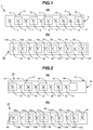
- a tri-band cross-polarization panel antenna 1 comprises a first antenna array 2 operating in a high frequency band Fa-Fb, a second antenna array 3 operating in another high frequency band Fc-Fd and a third antenna array 4 operating in a low frequency band Fe-Ff.
- the first antenna array 2 comprises an alignment of five radiating elements 5, 6, 7, 8, 9 with two crossed polarizations oriented +45° and -45° relative to the axis of the first antenna array 2 .
- the second antenna array 3 comprises, along the length of the first antenna array 2 , an alignment of five radiating elements 10, 11, 12, 13, 14 with two cross polarizations oriented +45° and -45° relative to the axis of the second antenna array 3 .
- the third antenna array 4 comprises an alignment of five radiating elements 15, 16, 17, 18, 19 concentrically disposed around certain radiating elements 6, 8, 10, 12, 14 belonging to the first antenna array 2 and to the second antenna array 3 .
- a first mode embodiment of a tri-band panel antenna 20 is depicted in Figure 1b .
- the dipoles 5a, 6a, 7a, 8a, 9a with polarity -45°, of the radiating elements 5, 6, 7, 8, 9 of the first antenna array 2 are moved towards the opposite end of the tri-band panel antenna 20 by a distance that here corresponds to five times the distance inter-elements, without their relative positioning being altered.
- the position of the dipoles 5b, 6b, 7b, 8b, 9b with polarity +45° of the radiating elements 5, 6, 7, 8, 9 of the first antenna array 2 remain unchanged.
- the dipoles 10a, 11 a, 12a, 13a, 14a with polarity -45 ° of the radiating elements 10, 11, 12, 13, 14 of the second antenna array 3 are now moved towards the other end of the tri-band panel antenna 20 by a distance that here corresponds to five times the distance inter-elements, without their relative positioning being altered.
- the position of the dipoles 10b, 11 b, 12b, 13b, 14b with polarity +45° of the radiating elements 10, 11, 12, 13, 14 of the second antenna array 3 remain unchanged.
- the distance inter-elements in the first antenna array 2 is the same as the distance inter-elements in the second antenna array 3 .
- the purpose of these movements is to obtain the maximum physical distance between the two polarizations of each radiating element of the first antenna array 2 and of the second antenna array 3 .
- the radiating elements 15, 16, 17, 18, 19 of the third antenna array 4 are not moved.
- the first polarizations 5a, 6a, 7a, 8a, 9a belonging to the first antenna array 2 are therefore crossed with the second polarizations 10b, 11 b, 12b, 13b, 14b belonging to the second antenna array 3 .
- the first polarizations 10a, 11 a, 12a, 13a, 14a belonging to the second antenna array 3 are therefore crossed with the second polarizations 5b, 6b, 7b, 8b, 9b belonging to the first antenna array 2
- these dipole movements consist of altering the branching of the feed lines connected to each of the dipoles to be moved. It is understood that the movement of the dipoles with polarity-45° that has just been described could also have been described for polarity+45°, in which case the positions of the dipoles with polarity -45° would remain unchanged.
- Figure 2a depicts another known configuration of a tri-band panel antenna 30 comprising a first antenna array 31 operating within a high-frequency band Fa-Fb, a second antenna array 32 operating within another high-frequency band Fc-Fd and a third antenna array 33 operating within a low-frequency band Fe-Ff.
- the first antenna array 31 comprises an alignment of four radiating elements 34, 35, 36, 37 with two cross polarizations oriented +45° and -45° relative to the axis of the first antenna array 31 .
- the second antenna array 32 comprises, along the length of the first antenna array 31 , an alignment of four radiating elements 38, 39, 40, 41 with two cross polarizations oriented +45° and -45° relative to the axis of the second antenna array 32 .
- the third antenna array 33 comprises an alignment of five radiating elements 42, 43, 44, 45, 46 , four radiating elements 42, 43, 44, 45 of the third antenna array 33 are concentrically disposed around radiating elements 34, 36, 38, 40 belonging to the first antenna array 31 and to the second antenna array 32 .
- the chassis of the tri-band panel antenna 30 two positions are unoccupied: one placed at the center of the radiating element 46 of the third antenna array 33 and the other that is contiguous with it.
- a second mode embodiment of a tri-band panel antenna 47 is depicted in Figure 2b .
- the dipoles 34a, 35a, 36a, 37a with polarity -45° of the radiating elements 34, 35, 36, 37 of the first antenna array 31 are moved towards the opposite end of the tri-band panel antenna 47 by a distance that here corresponds to six times the distance inter-elements, without their relative positioning being altered.
- the positions of the dipoles 34b, 35b, 36b, 37b with polarity +45° of the radiating elements 34, 35, 36, 37 of the first antenna array 31 remain unchanged
- the dipoles 38a, 39a, 40a, 41 a with polarity -45° of the radiating elements 38, 39, 40, 41 of the second antenna array 32 are now moved in the reverse direction, towards the other end of the tri-band panel antenna 47 by a distance that here corresponds to three times the distance inter-elements, without their relative positioning being altered.
- the dipoles 38b, 39b, 40b, 41b with polarity +45° of the radiating elements 38, 39, 40, 41 of the second antenna array 32 were shifted by the distance inter-elements in the same direction as the dipoles 34a, 35a, 36a, 37a belonging to the first antenna array 31 , so as to occupy the free positions, without their relative positioning being altered.
- the purpose of these movements is to obtain the maximum physical distance between the two polarizations of each radiating element of the first antenna array 31 and the second antenna array 32 by occupying all the available space.
- the radiating elements 42, 43, 44, 45, 46 of the third antenna array 33 are not moved. Naturally, these movements may only be performed provided that the distance inter-elements within the first antenna array 31 is the same as the distance inter-elements in the second antenna array 32 .
- Parasitic elements are often added to the antenna arrays in order to improving the decoupling between the radiating elements.
- the term parasitic element refers to a conductive element which is not fed, neither directly, nor indirectly, by way of the dipole. It is often designated by the term "director".
- the physical distance between the dipoles of a single radiating element makes it possible to reduce the needed number of parasitic elements.
- the free positions adjacent to the dipoles 34b, 41a 38b, 37a may be occupied by unfed parasitic elements 48 . In such a case, the polarizations 34b, 41a 38b, 37a belonging to the first antenna array 31 and to the second antenna array 32 are crossed with a parasitic element.
- FIG. 3a depicts a dual-band panel antenna 50 in a known configuration.
- the dual-band panel antenna 50 comprises a first antenna array 51 operating within a high-frequency band Fc-Fd and a second antenna array 52 operating within a low-frequency band Fe-Ff.
- the first antenna array 51 comprises an alignment of fourteen radiating elements 53-66 with two cross polarizations oriented +45° and -45° relative to the axis of the first antenna array 51 .
- the second antenna array 52 comprises, coaxially with the first antenna array 51 , an alignment of ten radiating elements 67-76 , the radiating elements 67, 68, 69, 70, 71, 72, 73 of the second antenna array 52 being concentrically disposed around certain radiating elements 53, 55, 57, 59, 61, 63, 65 belonging to the first antenna array 51 .
- multiple positions are unoccupied: some placed at the center of the radiating elements 74, 75, 76 of the second antenna array 52 and the others placed between the radiating elements 74 and 75 and between the radiating elements 75 and 76 .
- FIG. 3b One embodiment of a dual-band panel antenna 77 is depicted in Figure 3b .
- the dipoles 53a-66a with polarity -45° of the radiating elements 53-66 of the first antenna array 51 are moved towards the opposite end of the dual-band panel antenna 77 by a distance here equal to five times the distance inter-elements so as to occupy the free positions, without their relative positioning being altered.
- the positions of the dipoles 53b-66b with polarity +45° of the radiating elements 53-66 of the first antenna array 51 remain unchanged
- the radiating elements 67-76 of the second antenna array 52 are not moved.
- This embodiment leads to a high total level of decoupling between the two polarizations. This is the same as with the tri-band panel antenna 47 .
- the free positions adjacent to the dipoles 53b, 54b, 55b, 56b, 57b, 62a, 63a, 64a, 65a, 66a may be occupied by unfed parasitic elements.
- the polarities 53b, 54b, 55b, 56b, 57b, 62a, 63a, 64a, 65a, 66a are then crossed with parasitic elements
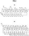
- a four-band panel antenna 80 comprises a first antenna array 81 operating within a high-frequency band Fa-Fb, a second antenna array 82 operating within another high-frequency band Fc-Fd, a third antenna array 83 operating within a low-frequency band Fe-Ff and a fourth antenna array 84 operating within a high-frequency band Fg-Fh.
- the first antenna array 81 comprises an alignment of five radiating elements 85, 86, 87, 88, 89 with two cross polarizations oriented +45° and -45° relative to the axis of the first antenna array 81 .
- the second antenna array 82 comprises, along the length of the first antenna array 81 , an alignment of five radiating elements 90, 91, 92, 93, 94 with two cross polarizations oriented +45° and -45° relative to the axis of the second antenna array 82 .
- the third antenna array 83 comprises an alignment of five radiating elements 95, 96, 97, 98, 99 concentrically disposed around certain radiating elements 86, 88, 90, 92, 94 belonging to the first antenna array 81 and to the second antenna array 82 .
- the fourth antenna array 84 comprises, in parallel with the three other antenna arrays 81, 82, 83, an alignment of ten radiating elements 100-109 with two cross polarizations oriented +45° and -45° relative to the axis of the fourth antenna array 84:
- FIG. 4b One embodiment of a four-band panel antenna 110 is depicted in Figure 4b .
- the dipoles 85a, 86a, 87a, 88a, 89a with polarity -45°, of the radiating elements 85, 86, 87, 88, 89 of the first antenna array 81 are moved towards the opposite end of the four-band panel antenna 110 by a distance that here corresponds to five times the distance inter-elements, without their relative positioning being altered.
- the positions of the dipoles 85b, 86b, 87b, 88b, 89b with polarity +45of the radiating elements 85, 86, 87, 88, 89 of the first antenna array 81 remain unchanged.
- the dipoles 90a, 91 a, 92a, 93a, 94a with polarity -45° of the radiating elements 90, 91, 92, 93, 94 of the second antenna array 82 are now moved towards the other end of the tri-band panel antenna 110 by a distance that here corresponds to five times the distance inter-elements, without their relative positioning being altered.
- the positions of the dipoles 90b, 91b, 92b, 93b, 94b with polarity +45° of the radiating elements 90, 91, 92, 93, 94 of the second antenna array 82 remain unchanged.
- the radiating elements 95, 96, 97, 98, 99 of the third antenna array 83 are not moved.
- the distance inter-elements in the first antenna array 81 is the same as the distance inter-elements in the second antenna array 82.
- the dipoles 100a, 101a, 102a, 103a, 104a, 105a, 106a, 107a, 108a, 109a with polarity-45° of the radiating elements 100-109 of the fourth antenna array 84 are now moved in a parallel orientation and in the same direction as the movement of the dipoles 85a, 86a, 87a, 88a, 89a of the radiating elements 85, 86, 87, 88, 89 of the first antenna array 81 , by a distance that here corresponds to twice the distance inter-elements, without their relative positioning being altered.
- the positions of the dipoles 100b, 101b, 102b, 103b, 104b, 105b, 106b, 107b, 108b, 109b with polarity +45° of the radiating elements 100-109 of the fourth antenna array 84 remain unchanged
- the polarities 100b, 101b, 108a, 109a may be crossed with parasitic elements.
- FIG. 5a depicts a five-band panel antenna 120 in a known configuration.
- the five-band panel antenna 120 comprises a first antenna array 121 operating within a high-frequency band Fa-Fb, a second antenna array 122 operating within another high-frequency band Fc-Fd, a third antenna array 123 operating within a low-frequency band Fe-Ff, a fourth antenna array 124 operating within a high-frequency band Fg-Fh, and a fifth antenna array 125 operating within a high-frequency band Fi-Fj.
- the first antenna array 121 comprises an alignment of five radiating elements 126, 127, 128, 129, 130 with two crossed polarizations oriented +45° and -45° relative to the axis of the first antenna array 121.
- the second antenna array 122 comprises, along the length of the first antenna array 121 , an alignment of five radiating elements 131, 132, 133, 134, 135 with two cross polarizations oriented +45° and -45° relative to the axis of the second antenna array 122 .
- the third antenna array 123 comprises an alignment of five radiating elements 136,137,138,139,140 concentrically disposed around certain radiating elements 127, 129, 131, 133, 135 belonging to the first antenna array 121 and to the second antenna array 122 .
- the fourth antenna array 124 comprises, parallel to the first three antenna arrays 121, 122, 123, an alignment of six radiating elements 141, 142, 143, 144, 145, 146 with two cross polarizations oriented +45° and -45° relative to the axis of the fourth antenna array 124 .
- the fifth antenna array 125 comprises, along the length of the fourth antenna array 124 and parallel to the first three antenna arrays 121, 122, 123, an alignment of six radiating elements 147, 148, 149, 150, 151, 152 with two cross polarizations oriented +45° and -45° relative to the axis of the fifth antenna 125 .
- FIG. 5b One embodiment of a five-band panel antenna 153 is depicted in Figure 5b .
- the dipoles 126a, 127a, 128a, 129a, 130a with polarity -45°, of the radiating elements 126 , 127, 128, 129, 130 of the first antenna array 121 are moved towards the opposite end of the five-band panel antenna 153 by a distance that here corresponds to five times the distance inter-elements, without their relative positioning being altered.
- the positions of the dipoles 126b, 127b, 128b, 129b, 130b with polarity +45° of the radiating elements 126, 127, 128, 129, 130 of the first antenna array 121 remain unchanged.
- the dipoles 131a, 132a, 133a, 134a, 135a with polarity -45° of the radiating elements 131, 132, 133, 134, 135 of the second antenna array 122 are now moved towards the other end of the five-band panel antenna 153 by a distance that here corresponds to five times the distance inter-elements, without their relative positioning being altered. However, the positions of the dipoles 131 b, 132b, 133b, 134b, 135b with polarity +45° of the radiating elements 131, 132, 133, 134, 135 of the second antenna array 122 remain unchanged.
- the radiating elements 136, 137, 138, 139, 140 of the third antenna array 123 are not moved.
- the distance inter-elements in the first antenna array 121 is the same as the distance inter-elements in the second antenna array 122 .
- the dipoles 141a, 142a, 143a, 144a, 145a, 146a with polarity-45° of the radiating elements 141, 142, 143, 144, 145, 146 of the fourth antenna array 124 are now moved in a parallel orientation and in the same direction as the movement of the dipoles 126a, 127a, 128a, 129a, 130a of the radiating elements 126, 127, 128, 129, 130 of the first antenna array 121 , by a distance that here corresponds to six times the distance inter-elements, without their relative positioning being altered.
- the positions of the dipoles 141b, 142b, 143b, 144b, 145b, 146b with polarity +45° of the radiating elements 141, 142, 143, 144, 145, 146 of the fourth antenna array 124 remain unchanged
- the dipoles 147a, 148a, 149a, 150a, 151a, 152a with polarity-45° of the radiating elements 147, 148, 149, 150, 151, 152 of the fifth antenna array 125 now moved in a parallel orientation and in the same direction as the movement of the dipoles 131a, 132a, 133a, 134a, 135a of the radiating elements 131, 132, 133, 134, 135 of the second antenna array 122 , by a distance that here corresponds to six times the distance inter-elements, without their relative positioning being altered.
- the positions of dipoles 147b, 148b, 149b, 150b, 151b, 152b with polarity +45° of the radiating elements 147, 148, 149, 150, 151, 152 of the fifth antenna array 125 remain unchanged
- the distance inter-elements in the fourth antenna array 124 is the same as the distance inter-elements in the second antenna array 125 . This distance inter-elements may be equal to or different from the first 121 and second 122 antenna arrays.
Landscapes
- Physics & Mathematics (AREA)
- Electromagnetism (AREA)
- Engineering & Computer Science (AREA)
- Computer Networks & Wireless Communication (AREA)
- Variable-Direction Aerials And Aerial Arrays (AREA)
- Waveguide Aerials (AREA)
- Aerials With Secondary Devices (AREA)
Description
- This invention relates to the field of telecommunication antennas transmitting radio waves in the hyperfrequency range, using radiating elements. It particularly relates to antennas called crosspolar multiband panel antennas. A panel antenna is made up of multiple antenna arrays, such as patch antenna arrays or dipole arrays that work in a given frequency band, which are more particularly in a given frequency band that are more particularly intended for cellular telephony applications.
- A telecommunication antenna, for example one installed in a base station of a mobile telephony network, sends and receives radio waves along frequencies specific to the telecommunication system operated by that antenna. To do so, the base station supplies each panel antenna with frequency waves within the frequency band that it operates, such as, for example, "Global System for Mobile communications" GSM (870-960 MHz), "Digital Cellular System" DCS (1710-1880 MHz), "Universal Mobile Telephone Service" UMTS (1900-2170 MHz), and LTE (for "Long Term Evolution") for 700MHz and 2600MHz frequencies. In order to avoid increasing the number of antennas already installed, multi-band panel antennas are used that result from combining multiple series of radiating elements forming just as many antenna arrays, respectively belonging to separate telecommunication systems grouped into a single chassis formed of a shared reflector protected by a single radome.
- Multiple configurations have been proposed to construct a crosspolar multiband panel antenna, made up of orthogonal-polarization antenna arrays operating in separate frequency bands, in which the radiating elements are inside the same chassis. A configuration called "side by side" comprising two parallel rows of radiating elements, placed at least a half-wavelength apart for the highest frequency band. Another configuration called "colinear" or "concentric", in which the orthogonal-polarization radiating elements operating on a first frequency band are concentrically disposed, around orthogonal-polarization radiating elements operating on a second frequency band, all of those orthogonal-polarization radiating elements being aligned along a single axis. Yet another configuration consists of disposing alignments of radiating elements all in a line with one another. In order to reduce interactions between radiating elements operating within the same frequency band, unfed parasitic elements may be added. International application
WO 2007/011295 discloses an antenna arrangement with interleaved antenna elements operating in two separate frequency bands. - All of these configurations aim to combine antenna arrays that operate in different frequency bands within a single chassis that has a fixed, limited volume, each antenna array having its own feed adapted to its own operating frequency band. This grouping is guided by considerations such as reducing the visual impact of the antennas, reducing the pylons' load, etc. However, within the increase in the number of frequency bands, and therefore in the number of antenna arrays within a single volume, such configurations lead to an increase in coupling between the radiating elements operating within each of those antenna arrays, which is a drawback in particular for MIMO applications and that requiring a diversity of signals.
- In a crosspolar multiband panel antenna, the effectiveness in MIMO applications and that require a diversity of signals is related to decoupling between the polarizations of the radiating elements within each frequency band. The decoupling between the polarizations of the radiating elements is produced by the geometry of the radiating elements on the reflector shared by the antenna arrays, as well as by the presence of certain parasitic elements that make it possible to influence these coupling parameters. Assuming a crosspolar multiband panel antenna comprising a plurality of antenna arrays (at least 2, and up to 5 or even more) having separate operating frequency bands, each made up of aligned radiating elements placed under a single radome and carried by the same reflector, it is understood that these decoupling techniques become increasingly complicated to implement, because there is not enough physical space available within the chassis' overall volume to be able to maintain the same general form factor as traditional panel antennas that operate in at least two distinct frequency bands.
- It is therefore a purpose of the present invention to improve decoupling between the two polarizations of the radiating elements of an antenna array operating within the same frequency band, without considerably increasing the size of a crosspolar multiband panel antenna, nor the weight or cost associated with it.
- The object of the present invention is a crosspolar multiband panel antenna comprising, within a single chassis, at least two antenna arrays operating within different frequency bands, each antenna array comprising at least two cross-polarization radiating elements separated by a distance inter-elements, each radiating element comprising a first polarization and a second polarization, the second polarization being orthogonal to the first polarization, the first polarization and the second polarization belonging to the same radiating element are physically separated by a distance equal to or greater than the distance inter-elements.
- The radiating element is defined by one row in the alignment forming the antenna array. A dual-polarization radiating element is, for example, formed of two independent dipoles, each with a given polarization. Here, "polarization" denotes both a dipole and a planar antenna, known as a "patch" antenna.
- This is a new architecture of a crosspolar multiband panel antenna in which physical decoupling is combined with the traditionally used polarization decoupling, for each of the radiating elements, thereby allowing them to improve MIMO applications and applications that require diversity of signals.
- The main idea of the invention is to not physically co-locate the two cross polarizations that correspond to a radiating element of the same row of an antenna array. This may be applied to some or all of the antenna arrays that form the multiband panel antenna (dual band, tri-band, four-band, etc.)
- According to one aspect, the first polarizations that belong to one antenna array form a first alignment, and the second polarizations belonging to the same antenna array form a second alignment, the positions of the first and second polarizations belonging to the same radiating element being analogous within the first and second alignment, respectively.
- According to another aspect, the first polarizations and the second polarizations of a single antenna array are separated by one another by a distance inter-elements within their respective alignments.
- According to yet another aspect, the distance inter-elements within the first antenna array is equal to the distance inter-elements in the second antenna array.
- According to one variant, a first polarization belonging to a first antenna array may be crossed with a second polarization belonging to a second antenna array.
- According to another variant, a polarization belonging to an antenna array may be crossed with a parasitic element.
- According to one embodiment, all of the first polarizations belonging to one antenna array and all of the second polarizations belonging to the same antenna array are disposed with respect to one another in such a way as to increase the distance separating the first polarization from the second polarization of a single radiating element.
- According to another embodiment, the polarizations are disposed in such a way as to occupy all the available space within the panel antenna's chassis.
- One advantage of the invention is to improve decoupling between the cross-polarization radiating elements of the antenna arrays composing a multiband panel antenna combining the spatial decoupling with the polarization decoupling for each radiating element in order to get better results for signal diversity algorithms and MIMO. It also makes it possible to simplify the design and overall internal structure of the crosspolar multiband panel antenna, without increasing the dimensions of the chassis, all while offering additional decoupling between the two polarizations owing to the distance physically separating them. It thereby makes it possible to increase decoupling between the polarizations for each frequency band (improved by 5-10 dB).
- The invention applies to any type of crosspolar multiband panel antenna made up of antenna arrays, regardless of the polarization angle. The invention may also be used without any limitation in the number of antenna arrays, i.e. the number of frequency bands in question.
- Other characteristics and advantages of the present invention will become apparent upon reading the following description of one embodiment, which is naturally given by way of a non-limiting example, and in the attached drawing, in which:
-
Figures 1a and 1b depict a first embodiment of a tri-band array, -
Figures 2a and 2b depict a second embodiment of a tri-band array, -
Figures 3a and 3b depict an embodiment of a dual-band array, -
Figures 4a and 4b depict an embodiment of a four-band array, -
Figures 5a and 5b depict an embodiment of a five-band array. - The radiating elements of a single antenna array are devoted to sending/receiving on a single frequency band. A dual-polarization radiating element is normally formed of two independent dipoles each comprising two colinear conductor arms with a given polarization, positive or negative, for sending/receiving radio signals. What will be described for each polarization, represented here by a dipole, also applies when the polarization is represented by a planar antenna or "patch" antenna. The radiating elements are installed longitudinally aligned above a reflector. Depending on their orientation within space, the dipoles may radiate or receive electromagnetic waves along two polarization channels, for example, a horizontal polarization channel, and a vertical polarization channel, or two polarization channels oriented +45° and -45° relative to the vertical. Each dipole of a radiating element is linked by a feed line to an outside source of power that defines its phase and amplitude
- In the known configuration depicted in
Figure 1a , a tri-bandcross-polarization panel antenna 1 comprises afirst antenna array 2 operating in a high frequency band Fa-Fb, asecond antenna array 3 operating in another high frequency band Fc-Fd and athird antenna array 4 operating in a low frequency band Fe-Ff. Thefirst antenna array 2 comprises an alignment of fiveradiating elements first antenna array 2. Thesecond antenna array 3 comprises, along the length of thefirst antenna array 2, an alignment of fiveradiating elements second antenna array 3. Finally, thethird antenna array 4 comprises an alignment of fiveradiating elements radiating elements first antenna array 2 and to thesecond antenna array 3. - A first mode embodiment of a tri-band
panel antenna 20 is depicted inFigure 1b . Thedipoles radiating elements first antenna array 2 are moved towards the opposite end of the tri-bandpanel antenna 20 by a distance that here corresponds to five times the distance inter-elements, without their relative positioning being altered. However, the position of thedipoles radiating elements first antenna array 2 remain unchanged. In the reverse direction, thedipoles radiating elements second antenna array 3 are now moved towards the other end of the tri-bandpanel antenna 20 by a distance that here corresponds to five times the distance inter-elements, without their relative positioning being altered. However, the position of thedipoles radiating elements second antenna array 3 remain unchanged. In order for these movements to be possible, the distance inter-elements in thefirst antenna array 2 is the same as the distance inter-elements in thesecond antenna array 3. - The purpose of these movements is to obtain the maximum physical distance between the two polarizations of each radiating element of the
first antenna array 2 and of thesecond antenna array 3. The radiatingelements third antenna array 4 are not moved. Thefirst polarizations first antenna array 2 are therefore crossed with thesecond polarizations second antenna array 3. Likewise, thefirst polarizations second antenna array 3 are therefore crossed with thesecond polarizations first antenna array 2 - From a practical viewpoint, these dipole movements consist of altering the branching of the feed lines connected to each of the dipoles to be moved. It is understood that the movement of the dipoles with polarity-45° that has just been described could also have been described for polarity+45°, in which case the positions of the dipoles with polarity -45° would remain unchanged.
-
Figure 2a depicts another known configuration of atri-band panel antenna 30 comprising afirst antenna array 31 operating within a high-frequency band Fa-Fb, asecond antenna array 32 operating within another high-frequency band Fc-Fd and athird antenna array 33 operating within a low-frequency band Fe-Ff. Thefirst antenna array 31 comprises an alignment of four radiatingelements first antenna array 31. Thesecond antenna array 32 comprises, along the length of thefirst antenna array 31, an alignment of four radiatingelements second antenna array 32. Finally, thethird antenna array 33 comprises an alignment of five radiatingelements elements third antenna array 33 are concentrically disposed around radiatingelements first antenna array 31 and to thesecond antenna array 32. In the chassis of thetri-band panel antenna 30, two positions are unoccupied: one placed at the center of the radiatingelement 46 of thethird antenna array 33 and the other that is contiguous with it. - A second mode embodiment of a
tri-band panel antenna 47 is depicted inFigure 2b . Thedipoles elements first antenna array 31 are moved towards the opposite end of thetri-band panel antenna 47 by a distance that here corresponds to six times the distance inter-elements, without their relative positioning being altered. However, the positions of thedipoles elements first antenna array 31 remain unchanged Thedipoles elements second antenna array 32 are now moved in the reverse direction, towards the other end of thetri-band panel antenna 47 by a distance that here corresponds to three times the distance inter-elements, without their relative positioning being altered. However, thedipoles elements second antenna array 32 were shifted by the distance inter-elements in the same direction as thedipoles first antenna array 31, so as to occupy the free positions, without their relative positioning being altered. The purpose of these movements is to obtain the maximum physical distance between the two polarizations of each radiating element of thefirst antenna array 31 and thesecond antenna array 32 by occupying all the available space. The radiatingelements third antenna array 33 are not moved. Naturally, these movements may only be performed provided that the distance inter-elements within thefirst antenna array 31 is the same as the distance inter-elements in thesecond antenna array 32. - Parasitic elements are often added to the antenna arrays in order to improving the decoupling between the radiating elements. Here, the term parasitic element refers to a conductive element which is not fed, neither directly, nor indirectly, by way of the dipole. It is often designated by the term "director". The physical distance between the dipoles of a single radiating element makes it possible to reduce the needed number of parasitic elements. The free positions adjacent to the
dipoles 41a parasitic elements 48. In such a case, thepolarizations 41a first antenna array 31 and to thesecond antenna array 32 are crossed with a parasitic element. -
Figure 3a depicts a dual-band panel antenna 50 in a known configuration. The dual-band panel antenna 50 comprises afirst antenna array 51 operating within a high-frequency band Fc-Fd and asecond antenna array 52 operating within a low-frequency band Fe-Ff. Thefirst antenna array 51 comprises an alignment of fourteen radiating elements 53-66 with two cross polarizations oriented +45° and -45° relative to the axis of thefirst antenna array 51. Thesecond antenna array 52 comprises, coaxially with thefirst antenna array 51, an alignment of ten radiating elements 67-76, the radiatingelements second antenna array 52 being concentrically disposed aroundcertain radiating elements first antenna array 51. In the chassis of the dual-band panel antenna 50, multiple positions are unoccupied: some placed at the center of the radiatingelements second antenna array 52 and the others placed between the radiatingelements elements - One embodiment of a dual-
band panel antenna 77 is depicted inFigure 3b . Thedipoles 53a-66a with polarity -45° of the radiating elements 53-66 of thefirst antenna array 51 are moved towards the opposite end of the dual-band panel antenna 77 by a distance here equal to five times the distance inter-elements so as to occupy the free positions, without their relative positioning being altered. However, the positions of thedipoles 53b-66b with polarity +45° of the radiating elements 53-66 of thefirst antenna array 51 remain unchanged The radiating elements 67-76 of thesecond antenna array 52 are not moved. This embodiment leads to a high total level of decoupling between the two polarizations. This is the same as with thetri-band panel antenna 47. The free positions adjacent to thedipoles polarities - In a known configuration depicted in
Figure 4a , a four-band panel antenna 80 comprises afirst antenna array 81 operating within a high-frequency band Fa-Fb, asecond antenna array 82 operating within another high-frequency band Fc-Fd, athird antenna array 83 operating within a low-frequency band Fe-Ff and afourth antenna array 84 operating within a high-frequency band Fg-Fh. Thefirst antenna array 81 comprises an alignment of five radiatingelements first antenna array 81. Thesecond antenna array 82 comprises, along the length of thefirst antenna array 81, an alignment of five radiatingelements second antenna array 82. Thethird antenna array 83 comprises an alignment of five radiatingelements certain radiating elements first antenna array 81 and to thesecond antenna array 82. Finally, thefourth antenna array 84 comprises, in parallel with the threeother antenna arrays - One embodiment of a four-
band panel antenna 110 is depicted inFigure 4b . Thedipoles elements first antenna array 81 are moved towards the opposite end of the four-band panel antenna 110 by a distance that here corresponds to five times the distance inter-elements, without their relative positioning being altered. However, the positions of thedipoles elements first antenna array 81 remain unchanged. In the reverse direction, thedipoles elements second antenna array 82 are now moved towards the other end of thetri-band panel antenna 110 by a distance that here corresponds to five times the distance inter-elements, without their relative positioning being altered. However, the positions of thedipoles elements second antenna array 82 remain unchanged. The radiatingelements third antenna array 83 are not moved. The distance inter-elements in thefirst antenna array 81 is the same as the distance inter-elements in thesecond antenna array 82. - The dipoles 100a, 101a, 102a, 103a, 104a, 105a, 106a, 107a, 108a, 109a with polarity-45° of the radiating elements 100-109 of the
fourth antenna array 84 are now moved in a parallel orientation and in the same direction as the movement of thedipoles elements first antenna array 81, by a distance that here corresponds to twice the distance inter-elements, without their relative positioning being altered. As before, the positions of thedipoles fourth antenna array 84 remain unchanged In this case, thepolarities -
Figure 5a depicts a five-band panel antenna 120 in a known configuration. The five-band panel antenna 120 comprises afirst antenna array 121 operating within a high-frequency band Fa-Fb, asecond antenna array 122 operating within another high-frequency band Fc-Fd, athird antenna array 123 operating within a low-frequency band Fe-Ff, afourth antenna array 124 operating within a high-frequency band Fg-Fh, and afifth antenna array 125 operating within a high-frequency band Fi-Fj. Thefirst antenna array 121 comprises an alignment of five radiatingelements first antenna array 121. Thesecond antenna array 122 comprises, along the length of thefirst antenna array 121, an alignment of five radiatingelements second antenna array 122. Thethird antenna array 123 comprises an alignment of five radiating elements 136,137,138,139,140 concentrically disposed aroundcertain radiating elements first antenna array 121 and to thesecond antenna array 122. Thefourth antenna array 124 comprises, parallel to the first threeantenna arrays elements fourth antenna array 124. Finally, thefifth antenna array 125 comprises, along the length of thefourth antenna array 124 and parallel to the first threeantenna arrays elements fifth antenna 125. - One embodiment of a five-
band panel antenna 153 is depicted inFigure 5b . Thedipoles elements first antenna array 121 are moved towards the opposite end of the five-band panel antenna 153 by a distance that here corresponds to five times the distance inter-elements, without their relative positioning being altered. However, the positions of thedipoles elements first antenna array 121 remain unchanged. The dipoles 131a, 132a, 133a, 134a, 135a with polarity -45° of the radiatingelements second antenna array 122 are now moved towards the other end of the five-band panel antenna 153 by a distance that here corresponds to five times the distance inter-elements, without their relative positioning being altered. However, the positions of thedipoles elements second antenna array 122 remain unchanged. The radiatingelements third antenna array 123 are not moved. The distance inter-elements in thefirst antenna array 121 is the same as the distance inter-elements in thesecond antenna array 122. - Furthermore, the dipoles 141a, 142a, 143a, 144a, 145a, 146a with polarity-45° of the radiating
elements fourth antenna array 124 are now moved in a parallel orientation and in the same direction as the movement of thedipoles elements first antenna array 121, by a distance that here corresponds to six times the distance inter-elements, without their relative positioning being altered. The positions of thedipoles elements fourth antenna array 124 remain unchanged Finally, the dipoles 147a, 148a, 149a, 150a, 151a, 152a with polarity-45° of the radiatingelements fifth antenna array 125 now moved in a parallel orientation and in the same direction as the movement of the dipoles 131a, 132a, 133a, 134a, 135a of the radiatingelements second antenna array 122, by a distance that here corresponds to six times the distance inter-elements, without their relative positioning being altered. The positions ofdipoles elements fifth antenna array 125 remain unchanged The distance inter-elements in thefourth antenna array 124 is the same as the distance inter-elements in thesecond antenna array 125. This distance inter-elements may be equal to or different from the first 121 and second 122 antenna arrays.
Claims (8)
- A crosspolar multiband panel antenna (77), comprising within a single chassis, at least one first antenna array (51) and a second antenna array (52) operating within different frequency bands, each antenna array (51, 52) comprising at least two cross-polarization radiating elements (53-67) separated by a distance inter-elements, each radiating element (53-67) comprising a first polarization and a second polarization, the second polarization being orthogonal to the first polarization, characterized in that the first polarization and the second polarization belonging to the same radiating element are physically separated by a distance equal to or greater than the distance inter-elements.
- A panel antenna according to claim 1, wherein the first polarizations that belong to one antenna array (51) form a first alignment, and the second polarizations belonging to the same antenna array (51) form a second alignment, the positions of the first and second polarizations belonging to the same radiating element being analogous within the first and second alignment, respectively.
- A panel antenna according to claim 2, the first polarizations and the second polarizations of a single antenna array are separated by one another by a distance inter-elements within their respective alignments.
- A panel antenna according to one of the claims 1 to 3, wherein the distance inter-elements in the first antenna array (51) is equal to the distance inter-elements in the second antenna array (52).
- Antennas according to one of the claims 1 to 4, wherein a first polarization belonging to a first antenna array (51) may be crossed with a second polarization belonging to a second antenna array (52).
- Antennas according to one of the claims 1 to 4, wherein a polarization belonging to an antenna array may be crossed with a parasitic element.
- A panel antenna according to one of the preceding claims, wherein all of the first polarizations belonging to one antenna array and all of the second polarizations belonging to the same antenna array are disposed with respect to one another in such a way as to increase the distance separating the first polarization from the second polarization of a single radiating element.
- Antennas according to one of the preceding claims, wherein the polarizations are disposed in such a way as to occupy all the available space within the panel antenna's chassis.
Applications Claiming Priority (2)
| Application Number | Priority Date | Filing Date | Title |
|---|---|---|---|
| FR1162388A FR2985099B1 (en) | 2011-12-23 | 2011-12-23 | CROSS-POLARIZED MULTIBAND PANEL ANTENNA |
| PCT/EP2012/076478 WO2013092908A1 (en) | 2011-12-23 | 2012-12-20 | Crosspolar multiband panel antenna |
Publications (2)
| Publication Number | Publication Date |
|---|---|
| EP2795722A1 EP2795722A1 (en) | 2014-10-29 |
| EP2795722B1 true EP2795722B1 (en) | 2016-03-16 |
Family
ID=47522555
Family Applications (1)
| Application Number | Title | Priority Date | Filing Date |
|---|---|---|---|
| EP12812963.2A Not-in-force EP2795722B1 (en) | 2011-12-23 | 2012-12-20 | Crosspolar multiband panel antenna |
Country Status (7)
| Country | Link |
|---|---|
| US (1) | US20140368395A1 (en) |
| EP (1) | EP2795722B1 (en) |
| JP (1) | JP5947399B2 (en) |
| KR (1) | KR101583180B1 (en) |
| CN (1) | CN104067442B (en) |
| FR (1) | FR2985099B1 (en) |
| WO (1) | WO2013092908A1 (en) |
Families Citing this family (27)
| Publication number | Priority date | Publication date | Assignee | Title |
|---|---|---|---|---|
| US9438278B2 (en) * | 2013-02-22 | 2016-09-06 | Quintel Technology Limited | Multi-array antenna |
| CN203813033U (en) * | 2013-12-23 | 2014-09-03 | 华为技术有限公司 | Multi-frequency array antenna |
| US9735476B2 (en) * | 2014-08-18 | 2017-08-15 | Accton Technology Corporation | Antenna apparatus and the MIMO communication device using the same |
| US10148012B2 (en) | 2015-02-13 | 2018-12-04 | Commscope Technologies Llc | Base station antenna with dummy elements between subarrays |
| DE102015005468A1 (en) * | 2015-04-29 | 2016-11-03 | Kathrein-Werke Kg | antenna |
| CN104993245A (en) * | 2015-06-25 | 2015-10-21 | 常州吉赫射频电子技术有限公司 | S-waveband communication-in-motion double-frequency circularly polarized micro-strip antenna and array thereof |
| US10381725B2 (en) * | 2015-07-20 | 2019-08-13 | Optimum Semiconductor Technologies Inc. | Monolithic dual band antenna |
| US10008782B2 (en) | 2016-06-24 | 2018-06-26 | Huawei Technologies Co., Ltd. | Low coupling full-duplex MIMO antenna array with coupled signal cancelling |
| US10910731B2 (en) | 2016-09-08 | 2021-02-02 | Commscope Technologies Llc | High performance flat panel antennas for dual band, wide band and dual polarity operation |
| WO2018046086A1 (en) * | 2016-09-08 | 2018-03-15 | Telefonaktiebolaget Lm Ericsson (Publ) | Antenna array and arrangement comprising an antenna array and a network node |
| US10270185B2 (en) | 2016-12-19 | 2019-04-23 | Huawei Technologies Co., Ltd. | Switchable dual band antenna array with three orthogonal polarizations |
| KR102633242B1 (en) * | 2017-02-28 | 2024-02-06 | 주식회사 케이엠더블유 | Dual polarized omni-directional antenna for mobile communication service |
| CN110622356B (en) | 2017-05-16 | 2021-08-03 | 华为技术有限公司 | an antenna |
| EP3669423B1 (en) * | 2017-09-12 | 2022-11-02 | Huawei Technologies Co., Ltd. | Multiband antenna array |
| EP3460906B1 (en) | 2017-09-20 | 2023-05-03 | Alcatel-Lucent Shanghai Bell Co., Ltd. | Wireless telecommunication network antenna |
| EP3460905B8 (en) * | 2017-09-21 | 2022-06-22 | Nokia Shanghai Bell Co., Ltd. | Multiple band antenna |
| CN107887684B (en) * | 2017-10-27 | 2019-11-05 | 京信通信系统(中国)有限公司 | Mimo antenna array, mimo antenna and base station |
| JP6470382B1 (en) * | 2017-11-09 | 2019-02-13 | 電気興業株式会社 | Frequency sharing array antenna |
| CN111615777B (en) * | 2018-01-26 | 2023-02-17 | 索尼公司 | antenna equipment |
| DE102018120612A1 (en) * | 2018-02-23 | 2019-08-29 | Kathrein Se | Multiband antenna arrangement for mobile radio applications |
| CN110071373B (en) * | 2018-03-12 | 2023-03-14 | 京信通信技术(广州)有限公司 | Multi-system integrated antenna |
| US11101562B2 (en) * | 2018-06-13 | 2021-08-24 | Mediatek Inc. | Multi-band dual-polarized antenna structure and wireless communication device using the same |
| CN111224224B (en) | 2018-11-27 | 2021-12-21 | 华为技术有限公司 | Antenna and array antenna |
| KR102305313B1 (en) * | 2019-10-07 | 2021-09-27 | 주식회사 케이엠더블유 | Antenna apparatus for spatial-polarization separation of beams using quadruple polarized antenna module array |
| WO2021145723A1 (en) | 2020-01-16 | 2021-07-22 | 삼성전자 주식회사 | Antenna module comprising floating radiators in communication system, and electronic device comprising same |
| GB2597269A (en) | 2020-07-17 | 2022-01-26 | Nokia Shanghai Bell Co Ltd | Antenna apparatus |
| US11843187B2 (en) * | 2021-04-26 | 2023-12-12 | Amazon Technologies, Inc. | Antenna module grounding for phased array antennas |
Family Cites Families (17)
| Publication number | Priority date | Publication date | Assignee | Title |
|---|---|---|---|---|
| ES2205898T3 (en) * | 1999-10-26 | 2004-05-01 | Fractus, S.A. | MULTIBAND CLUSTERS OF INTERRELATED ANTENNAS. |
| US6211841B1 (en) * | 1999-12-28 | 2001-04-03 | Nortel Networks Limited | Multi-band cellular basestation antenna |
| CN1507673A (en) * | 2001-04-16 | 2004-06-23 | �����ɷ� | Dual-band dual-polarized antenna array |
| US7817096B2 (en) * | 2003-06-16 | 2010-10-19 | Andrew Llc | Cellular antenna and systems and methods therefor |
| WO2007011295A1 (en) * | 2005-07-22 | 2007-01-25 | Powerwave Technologies Sweden Ab | Antenna arrangement with interleaved antenna elements |
| EP1935057B1 (en) * | 2005-10-14 | 2012-02-01 | Fractus S.A. | Slim triple band antenna array for cellular base stations |
| US7538740B2 (en) * | 2006-03-06 | 2009-05-26 | Alcatel-Lucent Usa Inc. | Multiple-element antenna array for communication network |
| KR100883408B1 (en) * | 2006-09-11 | 2009-03-03 | 주식회사 케이엠더블유 | Dual Band Dual Polarization Antenna for Mobile Communication Base Station |
| CN101459457B (en) * | 2007-12-12 | 2013-01-16 | 鼎桥通信技术有限公司 | Wave beam shaping method |
| US8942766B2 (en) * | 2008-08-28 | 2015-01-27 | Optis Cellular Technology, Llc | Arrangement for improved isolation between adjacent cell areas |
| US8692730B2 (en) * | 2009-03-03 | 2014-04-08 | Hitachi Metals, Ltd. | Mobile communication base station antenna |
| EP2226890A1 (en) * | 2009-03-03 | 2010-09-08 | Hitachi Cable, Ltd. | Mobile communication base station antenna |
| US8416142B2 (en) * | 2009-12-18 | 2013-04-09 | Kathrein-Werke Kg | Dual-polarized group antenna |
| EP2553764A1 (en) * | 2010-03-31 | 2013-02-06 | Andrew LLC | Omni-directional multiple-input multiple-output antenna system |
| EP2569824B1 (en) * | 2010-05-13 | 2019-03-13 | UTI Limited Partnership | Circularly polarized antenna having broadband characteristics |
| TR201808848T4 (en) * | 2012-01-13 | 2018-07-23 | Comba Telecom System China Ltd | AIR ANTENNA CONTROL SYSTEM AND MULTI-FREQUENCY COMMON AIR ANTENNA. |
| US9438278B2 (en) * | 2013-02-22 | 2016-09-06 | Quintel Technology Limited | Multi-array antenna |
-
2011
- 2011-12-23 FR FR1162388A patent/FR2985099B1/en not_active Expired - Fee Related
-
2012
- 2012-12-20 WO PCT/EP2012/076478 patent/WO2013092908A1/en not_active Ceased
- 2012-12-20 US US14/367,040 patent/US20140368395A1/en not_active Abandoned
- 2012-12-20 EP EP12812963.2A patent/EP2795722B1/en not_active Not-in-force
- 2012-12-20 JP JP2014548032A patent/JP5947399B2/en not_active Expired - Fee Related
- 2012-12-20 KR KR1020147020207A patent/KR101583180B1/en not_active Expired - Fee Related
- 2012-12-20 CN CN201280067882.2A patent/CN104067442B/en not_active Expired - Fee Related
Also Published As
| Publication number | Publication date |
|---|---|
| FR2985099A1 (en) | 2013-06-28 |
| KR101583180B1 (en) | 2016-01-07 |
| KR20140109986A (en) | 2014-09-16 |
| CN104067442A (en) | 2014-09-24 |
| WO2013092908A1 (en) | 2013-06-27 |
| EP2795722A1 (en) | 2014-10-29 |
| US20140368395A1 (en) | 2014-12-18 |
| JP2015507869A (en) | 2015-03-12 |
| FR2985099B1 (en) | 2014-01-17 |
| JP5947399B2 (en) | 2016-07-06 |
| CN104067442B (en) | 2016-08-24 |
Similar Documents
| Publication | Publication Date | Title |
|---|---|---|
| KR101583180B1 (en) | Crosspolar multiband panel antenna | |
| US10505609B2 (en) | Small cell beam-forming antennas | |
| EP2741369B1 (en) | Multi-mode antenna and base station | |
| EP3440741B1 (en) | Ultra wide band radiators and related antenna arrays | |
| EP1380069B1 (en) | Dual-band dual-polarized antenna array | |
| US8666450B2 (en) | Antenna and multi-input multi-output communication device using the same | |
| AU2014211633B2 (en) | An antenna arrangement and a base station | |
| US20150372397A1 (en) | An antenna arrangement and a base station | |
| US11108137B2 (en) | Compact omnidirectional antennas having stacked reflector structures | |
| CN113454922A (en) | Base station antenna with 4 ports having an array of radiating elements without using a duplexer | |
| EP3093919A1 (en) | Ultra-wideband dual-band cellular basestation antenna | |
| EP3025393B1 (en) | Stadium antenna | |
| US20150364832A1 (en) | An antenna arrangement and a base station | |
| US10958316B2 (en) | Multi-band base station antennas having MIMO arrays and related methods of operation | |
| US12597701B2 (en) | Base station antennas having f-style arrays that generate antenna beams having narrowed azimuth beamwidths | |
| EP3869614B1 (en) | Antenna and array antenna | |
| US11646502B2 (en) | Multi-band base station antenna | |
| CA3119944A1 (en) | Base station antenna | |
| CN213936537U (en) | Broadband dual-frequency fusion antenna array based on vertical oscillator | |
| US20260081343A1 (en) | Base station antenna with internal multiplexer |
Legal Events
| Date | Code | Title | Description |
|---|---|---|---|
| PUAI | Public reference made under article 153(3) epc to a published international application that has entered the european phase |
Free format text: ORIGINAL CODE: 0009012 |
|
| 17P | Request for examination filed |
Effective date: 20140723 |
|
| AK | Designated contracting states |
Kind code of ref document: A1 Designated state(s): AL AT BE BG CH CY CZ DE DK EE ES FI FR GB GR HR HU IE IS IT LI LT LU LV MC MK MT NL NO PL PT RO RS SE SI SK SM TR |
|
| DAX | Request for extension of the european patent (deleted) | ||
| REG | Reference to a national code |
Ref country code: DE Ref legal event code: R079 Ref document number: 602012015780 Country of ref document: DE Free format text: PREVIOUS MAIN CLASS: H01Q0001240000 Ipc: H01Q0005480000 |
|
| GRAP | Despatch of communication of intention to grant a patent |
Free format text: ORIGINAL CODE: EPIDOSNIGR1 |
|
| RIC1 | Information provided on ipc code assigned before grant |
Ipc: H01Q 5/48 20150101AFI20150728BHEP Ipc: H01Q 21/06 20060101ALI20150728BHEP Ipc: H01Q 1/24 20060101ALI20150728BHEP Ipc: H01Q 21/26 20060101ALI20150728BHEP Ipc: H01Q 21/30 20060101ALI20150728BHEP |
|
| INTG | Intention to grant announced |
Effective date: 20150825 |
|
| GRAS | Grant fee paid |
Free format text: ORIGINAL CODE: EPIDOSNIGR3 |
|
| GRAA | (expected) grant |
Free format text: ORIGINAL CODE: 0009210 |
|
| AK | Designated contracting states |
Kind code of ref document: B1 Designated state(s): AL AT BE BG CH CY CZ DE DK EE ES FI FR GB GR HR HU IE IS IT LI LT LU LV MC MK MT NL NO PL PT RO RS SE SI SK SM TR |
|
| REG | Reference to a national code |
Ref country code: GB Ref legal event code: FG4D |
|
| REG | Reference to a national code |
Ref country code: CH Ref legal event code: EP |
|
| REG | Reference to a national code |
Ref country code: IE Ref legal event code: FG4D |
|
| REG | Reference to a national code |
Ref country code: AT Ref legal event code: REF Ref document number: 781930 Country of ref document: AT Kind code of ref document: T Effective date: 20160415 |
|
| REG | Reference to a national code |
Ref country code: DE Ref legal event code: R096 Ref document number: 602012015780 Country of ref document: DE |
|
| REG | Reference to a national code |
Ref country code: NL Ref legal event code: MP Effective date: 20160316 |
|
| REG | Reference to a national code |
Ref country code: LT Ref legal event code: MG4D |
|
| PG25 | Lapsed in a contracting state [announced via postgrant information from national office to epo] |
Ref country code: HR Free format text: LAPSE BECAUSE OF FAILURE TO SUBMIT A TRANSLATION OF THE DESCRIPTION OR TO PAY THE FEE WITHIN THE PRESCRIBED TIME-LIMIT Effective date: 20160316 Ref country code: GR Free format text: LAPSE BECAUSE OF FAILURE TO SUBMIT A TRANSLATION OF THE DESCRIPTION OR TO PAY THE FEE WITHIN THE PRESCRIBED TIME-LIMIT Effective date: 20160617 Ref country code: NO Free format text: LAPSE BECAUSE OF FAILURE TO SUBMIT A TRANSLATION OF THE DESCRIPTION OR TO PAY THE FEE WITHIN THE PRESCRIBED TIME-LIMIT Effective date: 20160616 Ref country code: FI Free format text: LAPSE BECAUSE OF FAILURE TO SUBMIT A TRANSLATION OF THE DESCRIPTION OR TO PAY THE FEE WITHIN THE PRESCRIBED TIME-LIMIT Effective date: 20160316 |
|
| REG | Reference to a national code |
Ref country code: AT Ref legal event code: MK05 Ref document number: 781930 Country of ref document: AT Kind code of ref document: T Effective date: 20160316 |
|
| PG25 | Lapsed in a contracting state [announced via postgrant information from national office to epo] |
Ref country code: SE Free format text: LAPSE BECAUSE OF FAILURE TO SUBMIT A TRANSLATION OF THE DESCRIPTION OR TO PAY THE FEE WITHIN THE PRESCRIBED TIME-LIMIT Effective date: 20160316 Ref country code: LT Free format text: LAPSE BECAUSE OF FAILURE TO SUBMIT A TRANSLATION OF THE DESCRIPTION OR TO PAY THE FEE WITHIN THE PRESCRIBED TIME-LIMIT Effective date: 20160316 Ref country code: NL Free format text: LAPSE BECAUSE OF FAILURE TO SUBMIT A TRANSLATION OF THE DESCRIPTION OR TO PAY THE FEE WITHIN THE PRESCRIBED TIME-LIMIT Effective date: 20160316 Ref country code: LV Free format text: LAPSE BECAUSE OF FAILURE TO SUBMIT A TRANSLATION OF THE DESCRIPTION OR TO PAY THE FEE WITHIN THE PRESCRIBED TIME-LIMIT Effective date: 20160316 Ref country code: RS Free format text: LAPSE BECAUSE OF FAILURE TO SUBMIT A TRANSLATION OF THE DESCRIPTION OR TO PAY THE FEE WITHIN THE PRESCRIBED TIME-LIMIT Effective date: 20160316 |
|
| PG25 | Lapsed in a contracting state [announced via postgrant information from national office to epo] |
Ref country code: EE Free format text: LAPSE BECAUSE OF FAILURE TO SUBMIT A TRANSLATION OF THE DESCRIPTION OR TO PAY THE FEE WITHIN THE PRESCRIBED TIME-LIMIT Effective date: 20160316 Ref country code: PL Free format text: LAPSE BECAUSE OF FAILURE TO SUBMIT A TRANSLATION OF THE DESCRIPTION OR TO PAY THE FEE WITHIN THE PRESCRIBED TIME-LIMIT Effective date: 20160316 Ref country code: IS Free format text: LAPSE BECAUSE OF FAILURE TO SUBMIT A TRANSLATION OF THE DESCRIPTION OR TO PAY THE FEE WITHIN THE PRESCRIBED TIME-LIMIT Effective date: 20160716 |
|
| PG25 | Lapsed in a contracting state [announced via postgrant information from national office to epo] |
Ref country code: ES Free format text: LAPSE BECAUSE OF FAILURE TO SUBMIT A TRANSLATION OF THE DESCRIPTION OR TO PAY THE FEE WITHIN THE PRESCRIBED TIME-LIMIT Effective date: 20160316 Ref country code: PT Free format text: LAPSE BECAUSE OF FAILURE TO SUBMIT A TRANSLATION OF THE DESCRIPTION OR TO PAY THE FEE WITHIN THE PRESCRIBED TIME-LIMIT Effective date: 20160718 Ref country code: CZ Free format text: LAPSE BECAUSE OF FAILURE TO SUBMIT A TRANSLATION OF THE DESCRIPTION OR TO PAY THE FEE WITHIN THE PRESCRIBED TIME-LIMIT Effective date: 20160316 Ref country code: SK Free format text: LAPSE BECAUSE OF FAILURE TO SUBMIT A TRANSLATION OF THE DESCRIPTION OR TO PAY THE FEE WITHIN THE PRESCRIBED TIME-LIMIT Effective date: 20160316 Ref country code: AT Free format text: LAPSE BECAUSE OF FAILURE TO SUBMIT A TRANSLATION OF THE DESCRIPTION OR TO PAY THE FEE WITHIN THE PRESCRIBED TIME-LIMIT Effective date: 20160316 Ref country code: RO Free format text: LAPSE BECAUSE OF FAILURE TO SUBMIT A TRANSLATION OF THE DESCRIPTION OR TO PAY THE FEE WITHIN THE PRESCRIBED TIME-LIMIT Effective date: 20160316 Ref country code: SM Free format text: LAPSE BECAUSE OF FAILURE TO SUBMIT A TRANSLATION OF THE DESCRIPTION OR TO PAY THE FEE WITHIN THE PRESCRIBED TIME-LIMIT Effective date: 20160316 |
|
| REG | Reference to a national code |
Ref country code: DE Ref legal event code: R097 Ref document number: 602012015780 Country of ref document: DE |
|
| REG | Reference to a national code |
Ref country code: FR Ref legal event code: PLFP Year of fee payment: 5 |
|
| PG25 | Lapsed in a contracting state [announced via postgrant information from national office to epo] |
Ref country code: IT Free format text: LAPSE BECAUSE OF FAILURE TO SUBMIT A TRANSLATION OF THE DESCRIPTION OR TO PAY THE FEE WITHIN THE PRESCRIBED TIME-LIMIT Effective date: 20160316 Ref country code: BE Free format text: LAPSE BECAUSE OF FAILURE TO SUBMIT A TRANSLATION OF THE DESCRIPTION OR TO PAY THE FEE WITHIN THE PRESCRIBED TIME-LIMIT Effective date: 20160316 |
|
| PLBE | No opposition filed within time limit |
Free format text: ORIGINAL CODE: 0009261 |
|
| STAA | Information on the status of an ep patent application or granted ep patent |
Free format text: STATUS: NO OPPOSITION FILED WITHIN TIME LIMIT |
|
| PG25 | Lapsed in a contracting state [announced via postgrant information from national office to epo] |
Ref country code: DK Free format text: LAPSE BECAUSE OF FAILURE TO SUBMIT A TRANSLATION OF THE DESCRIPTION OR TO PAY THE FEE WITHIN THE PRESCRIBED TIME-LIMIT Effective date: 20160316 |
|
| 26N | No opposition filed |
Effective date: 20161219 |
|
| PG25 | Lapsed in a contracting state [announced via postgrant information from national office to epo] |
Ref country code: BG Free format text: LAPSE BECAUSE OF FAILURE TO SUBMIT A TRANSLATION OF THE DESCRIPTION OR TO PAY THE FEE WITHIN THE PRESCRIBED TIME-LIMIT Effective date: 20160616 |
|
| PG25 | Lapsed in a contracting state [announced via postgrant information from national office to epo] |
Ref country code: SI Free format text: LAPSE BECAUSE OF FAILURE TO SUBMIT A TRANSLATION OF THE DESCRIPTION OR TO PAY THE FEE WITHIN THE PRESCRIBED TIME-LIMIT Effective date: 20160316 |
|
| REG | Reference to a national code |
Ref country code: CH Ref legal event code: PL |
|
| PG25 | Lapsed in a contracting state [announced via postgrant information from national office to epo] |
Ref country code: MC Free format text: LAPSE BECAUSE OF FAILURE TO SUBMIT A TRANSLATION OF THE DESCRIPTION OR TO PAY THE FEE WITHIN THE PRESCRIBED TIME-LIMIT Effective date: 20160316 |
|
| REG | Reference to a national code |
Ref country code: IE Ref legal event code: MM4A |
|
| PG25 | Lapsed in a contracting state [announced via postgrant information from national office to epo] |
Ref country code: CH Free format text: LAPSE BECAUSE OF NON-PAYMENT OF DUE FEES Effective date: 20161231 Ref country code: LU Free format text: LAPSE BECAUSE OF NON-PAYMENT OF DUE FEES Effective date: 20161220 Ref country code: LI Free format text: LAPSE BECAUSE OF NON-PAYMENT OF DUE FEES Effective date: 20161231 |
|
| PG25 | Lapsed in a contracting state [announced via postgrant information from national office to epo] |
Ref country code: IE Free format text: LAPSE BECAUSE OF NON-PAYMENT OF DUE FEES Effective date: 20161220 |
|
| REG | Reference to a national code |
Ref country code: FR Ref legal event code: PLFP Year of fee payment: 6 |
|
| PGFP | Annual fee paid to national office [announced via postgrant information from national office to epo] |
Ref country code: DE Payment date: 20171211 Year of fee payment: 6 Ref country code: FR Payment date: 20171221 Year of fee payment: 6 |
|
| PGFP | Annual fee paid to national office [announced via postgrant information from national office to epo] |
Ref country code: GB Payment date: 20171221 Year of fee payment: 6 |
|
| PG25 | Lapsed in a contracting state [announced via postgrant information from national office to epo] |
Ref country code: HU Free format text: LAPSE BECAUSE OF FAILURE TO SUBMIT A TRANSLATION OF THE DESCRIPTION OR TO PAY THE FEE WITHIN THE PRESCRIBED TIME-LIMIT; INVALID AB INITIO Effective date: 20121220 |
|
| PG25 | Lapsed in a contracting state [announced via postgrant information from national office to epo] |
Ref country code: CY Free format text: LAPSE BECAUSE OF FAILURE TO SUBMIT A TRANSLATION OF THE DESCRIPTION OR TO PAY THE FEE WITHIN THE PRESCRIBED TIME-LIMIT Effective date: 20160316 Ref country code: MK Free format text: LAPSE BECAUSE OF FAILURE TO SUBMIT A TRANSLATION OF THE DESCRIPTION OR TO PAY THE FEE WITHIN THE PRESCRIBED TIME-LIMIT Effective date: 20160316 |
|
| PG25 | Lapsed in a contracting state [announced via postgrant information from national office to epo] |
Ref country code: MT Free format text: LAPSE BECAUSE OF NON-PAYMENT OF DUE FEES Effective date: 20161220 |
|
| PG25 | Lapsed in a contracting state [announced via postgrant information from national office to epo] |
Ref country code: TR Free format text: LAPSE BECAUSE OF FAILURE TO SUBMIT A TRANSLATION OF THE DESCRIPTION OR TO PAY THE FEE WITHIN THE PRESCRIBED TIME-LIMIT Effective date: 20160316 Ref country code: AL Free format text: LAPSE BECAUSE OF FAILURE TO SUBMIT A TRANSLATION OF THE DESCRIPTION OR TO PAY THE FEE WITHIN THE PRESCRIBED TIME-LIMIT Effective date: 20160316 |
|
| REG | Reference to a national code |
Ref country code: DE Ref legal event code: R119 Ref document number: 602012015780 Country of ref document: DE |
|
| GBPC | Gb: european patent ceased through non-payment of renewal fee |
Effective date: 20181220 |
|
| PG25 | Lapsed in a contracting state [announced via postgrant information from national office to epo] |
Ref country code: FR Free format text: LAPSE BECAUSE OF NON-PAYMENT OF DUE FEES Effective date: 20181231 Ref country code: DE Free format text: LAPSE BECAUSE OF NON-PAYMENT OF DUE FEES Effective date: 20190702 |
|
| PG25 | Lapsed in a contracting state [announced via postgrant information from national office to epo] |
Ref country code: GB Free format text: LAPSE BECAUSE OF NON-PAYMENT OF DUE FEES Effective date: 20181220 |