EP2795659B1 - An imaging mass spectrometer and a method of mass spectrometry - Google Patents
An imaging mass spectrometer and a method of mass spectrometry Download PDFInfo
- Publication number
- EP2795659B1 EP2795659B1 EP12816491.0A EP12816491A EP2795659B1 EP 2795659 B1 EP2795659 B1 EP 2795659B1 EP 12816491 A EP12816491 A EP 12816491A EP 2795659 B1 EP2795659 B1 EP 2795659B1
- Authority
- EP
- European Patent Office
- Prior art keywords
- sample
- ions
- energy
- mass spectrometer
- imaging mass
- Prior art date
- Legal status (The legal status is an assumption and is not a legal conclusion. Google has not performed a legal analysis and makes no representation as to the accuracy of the status listed.)
- Active
Links
- 238000000034 method Methods 0.000 title claims description 41
- 238000003384 imaging method Methods 0.000 title claims description 36
- 238000004949 mass spectrometry Methods 0.000 title description 5
- 150000002500 ions Chemical class 0.000 claims description 105
- 238000003795 desorption Methods 0.000 claims description 33
- 230000008569 process Effects 0.000 claims description 20
- 239000011159 matrix material Substances 0.000 claims description 8
- 238000001871 ion mobility spectroscopy Methods 0.000 claims description 4
- 239000000523 sample Substances 0.000 description 118
- 101710121996 Hexon protein p72 Proteins 0.000 description 6
- 101710125418 Major capsid protein Proteins 0.000 description 6
- 238000004458 analytical method Methods 0.000 description 5
- 238000001228 spectrum Methods 0.000 description 5
- 230000003760 hair shine Effects 0.000 description 3
- 239000000463 material Substances 0.000 description 3
- VYPSYNLAJGMNEJ-UHFFFAOYSA-N Silicium dioxide Chemical compound O=[Si]=O VYPSYNLAJGMNEJ-UHFFFAOYSA-N 0.000 description 2
- 238000002474 experimental method Methods 0.000 description 2
- 239000000203 mixture Substances 0.000 description 2
- 229920005439 Perspex® Polymers 0.000 description 1
- 238000003491 array Methods 0.000 description 1
- 230000008901 benefit Effects 0.000 description 1
- 239000012472 biological sample Substances 0.000 description 1
- 239000000919 ceramic Substances 0.000 description 1
- 230000003111 delayed effect Effects 0.000 description 1
- 238000000605 extraction Methods 0.000 description 1
- 238000013467 fragmentation Methods 0.000 description 1
- 238000006062 fragmentation reaction Methods 0.000 description 1
- 239000011521 glass Substances 0.000 description 1
- 239000000976 ink Substances 0.000 description 1
- 238000005259 measurement Methods 0.000 description 1
- 230000007246 mechanism Effects 0.000 description 1
- 239000002184 metal Substances 0.000 description 1
- 230000004048 modification Effects 0.000 description 1
- 238000012986 modification Methods 0.000 description 1
- 239000003973 paint Substances 0.000 description 1
- 229920003023 plastic Polymers 0.000 description 1
- 239000004033 plastic Substances 0.000 description 1
- 229920000642 polymer Polymers 0.000 description 1
- 239000004926 polymethyl methacrylate Substances 0.000 description 1
- 238000004445 quantitative analysis Methods 0.000 description 1
- 238000001004 secondary ion mass spectrometry Methods 0.000 description 1
- 239000000377 silicon dioxide Substances 0.000 description 1
- 239000007787 solid Substances 0.000 description 1
- 239000000758 substrate Substances 0.000 description 1
Images
Classifications
-
- H—ELECTRICITY
- H01—ELECTRIC ELEMENTS
- H01J—ELECTRIC DISCHARGE TUBES OR DISCHARGE LAMPS
- H01J49/00—Particle spectrometers or separator tubes
- H01J49/02—Details
- H01J49/10—Ion sources; Ion guns
- H01J49/16—Ion sources; Ion guns using surface ionisation, e.g. field-, thermionic- or photo-emission
- H01J49/161—Ion sources; Ion guns using surface ionisation, e.g. field-, thermionic- or photo-emission using photoionisation, e.g. by laser
- H01J49/164—Laser desorption/ionisation, e.g. matrix-assisted laser desorption/ionisation [MALDI]
-
- H—ELECTRICITY
- H01—ELECTRIC ELEMENTS
- H01J—ELECTRIC DISCHARGE TUBES OR DISCHARGE LAMPS
- H01J49/00—Particle spectrometers or separator tubes
- H01J49/0004—Imaging particle spectrometry
-
- H—ELECTRICITY
- H01—ELECTRIC ELEMENTS
- H01J—ELECTRIC DISCHARGE TUBES OR DISCHARGE LAMPS
- H01J49/00—Particle spectrometers or separator tubes
- H01J49/02—Details
- H01J49/04—Arrangements for introducing or extracting samples to be analysed, e.g. vacuum locks; Arrangements for external adjustment of electron- or ion-optical components
- H01J49/0409—Sample holders or containers
- H01J49/0418—Sample holders or containers for laser desorption, e.g. matrix-assisted laser desorption/ionisation [MALDI] plates or surface enhanced laser desorption/ionisation [SELDI] plates
-
- H—ELECTRICITY
- H01—ELECTRIC ELEMENTS
- H01J—ELECTRIC DISCHARGE TUBES OR DISCHARGE LAMPS
- H01J49/00—Particle spectrometers or separator tubes
- H01J49/26—Mass spectrometers or separator tubes
- H01J49/34—Dynamic spectrometers
- H01J49/40—Time-of-flight spectrometers
-
- H—ELECTRICITY
- H01—ELECTRIC ELEMENTS
- H01J—ELECTRIC DISCHARGE TUBES OR DISCHARGE LAMPS
- H01J49/00—Particle spectrometers or separator tubes
- H01J49/26—Mass spectrometers or separator tubes
- H01J49/34—Dynamic spectrometers
- H01J49/40—Time-of-flight spectrometers
- H01J49/405—Time-of-flight spectrometers characterised by the reflectron, e.g. curved field, electrode shapes
Definitions
- the present invention relates to an imaging mass spectrometer and a method of mass spectrometry. More specifically, but not exclusively, the present invention relates to an imaging mass spectrometer which allows multiple spots of a sample to be analyzed at the same time and a method employing such a mass spectrometer.
- a good way of performing this analysis is often by Matrix Assisted Laser Desorption lonisation (MALDI) imaging, where a user may fire a laser at one spot on the sample on a sample plate, and analyse the ions that are desorbed from that point on the sample. The ions produced may then be analysed by a mass spectrometer to indicate the content of the sample at that point. If one wishes to determine the composition of the whole of the sample then it is typically necessary to make multiple measurements at spaced apart spots. For a large sample this can be time consuming. This is undesirable as there is often competition for time on expensive mass spectrometers. Therefore, any way of reducing the analysis time required for a sample would be advantageous.
- MALDI Matrix Assisted Laser Desorption lonisation
- GB2423187 discloses a laser system for the ionisation of a sample by Matrix Assisted Laser Desorption in a mass spectrometric analysis, and associated method, according to the precharacterising features of claim 1.
- an imaging mass spectrometer comprising:
- the analyser is adapted to detect ions produced by the desorption process.
- the analyser is adapted to detect daughter ions produced by the decay of ions produced by the desorption process.
- the energy source can be a laser.
- Desorption of the ions can occur by Matrix Assisted Laser Desorption lonisation.
- the sample plate can be optically transparent.
- the imaging mass spectrometer according to the invention can further comprise a microlens array, the microlens array being adapted to receive the energy from the energy source and provide it at multiple spots on the sample.
- the imaging mass spectrometer can further comprise an homogeniser between the energy source and microlens array.
- the analyser can comprise a TOF.
- the analyser can further comprise a detector for detecting the arrival time and position of ions from the time of flight tube (TOF).
- TOF time of flight tube
- the detector can comprise an MCP array detector.
- the detector comprises a delay line detector.
- Said analyser can further comprise a reflectron.
- the energy source can be adapted to provide first and second pulses, one of the pulses being a high energy pulse and the other pulse being a low energy pulse.
- the invention also provides a method of imaging mass spectrometry comprising the steps of providing a sample on a sample plate; providing energy to multiple spots on the sample substantially simultaneously to produce ions from the sample by a desorption process wherein said energy is provided to the sample through the sample plate, and said energy is provided to said multiple spots at an angle substantially perpendicular to the surface of the sample; using one or more grid electrodes to focus the ions resulting from the desorption process; and detecting the arrival time and spot origin of ions resulting from the desorption process.
- the step of detecting the arrival time and spot origin can comprise detecting the arrival time and spot origin of ions produced by the desorption process.
- the step of detecting the arrival time and spot origin can comprise detecting the arrival time and spot origin of daughter ions produced by the decay of ions produced by the desorption process.
- the energy can be provided by a laser.
- the desorption of ions occurs by Matrix Assisted Laser Desorption lonisation.
- the energy can be provided to the sample through a microlens array.
- the step of detecting comprises providing the ions or daughter ions to a TOF and then to a detector.
- the step of providing energy can comprise the steps of providing energy in first and second pulses, one pulse being a low energy pulse and the other pulse being a high energy pulse.
- the present invention relates to an apparatus and method for performing Imaging Mass Spectrometry.
- the methods and devices of the present invention have particular application in the field of MALDI Mass Spectrometry, with the understanding that embodiments of the present invention have utility for performing Imaging mass spectrometry using imaging ion sources other than MALDI.
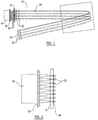
- FIG. 1 shows a schematic view of an imaging mass spectrometer 10 according to the invention.
- the imaging mass spectrometer 10 comprises a sample plate 12.
- a sample 14 is arranged on the top surface of the plate.
- An energy source 16 (in this case a laser) is pulsed to irradiate a microlens array 18 positioned to the rear of the sample plate 12 to produce an array of focused laser light which passes through the optically transparent sample plate 12 and irradiates defined spots 20 upon the sample 14.
- the ions then move away from the sample plate 12 in a generally perpendicular direction to the plate 12 into the analyser which detects the spot source and time of arrival of these ions.
- the analyser of the mass spectrometer comprises a plurality of focussing electrodes 22.
- the focussing electrodes are arranged to confine the ions into independent paths according to which defined point on the sample plate they have been desorbed from.
- the analyser further comprises a TOF 24 (Time Of Flight Tube) and a detector 26.
- a voltage is provided across the region in which the ions are travelling and is arranged to pulse the ions on their independent paths into the TOF,
- the ions which exit the TOF are received by the detector. Ions will arrive at the detector according to their mass to charge ratio.
- the ions produced from a given spot on the sample all hit the detector at the same known point or region 28. Ions produced from a different spot on the sample hit the detector at a different point or region 28.
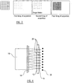
- FIG. 2 shows a microlens array 18 and sample plate 12 of an imaging mass spectrometer according to the invention.
- a sample plate 12 is provided with a sample substrate 14 placed on the top surface of the plate 12.
- a laser 16 is pulsed to irradiate a homogeniser (not shown), placed between the laser 16 and the sample plate 12 in order to create a uniform light intensity across the laser beam.
- the beam then irradiates the microlens array 18 positioned to the rear of the sample plate 12 to produce an array of focused laser light beams each of the same intensity.
- These irradiate the sample at a plurality of spots 20 causing ions to uniformly desorb from the top surface of the sample 14.
- the analysis of the ions produced by this means would then potentially be similar to that described with relation to figure 1 .
- Figure 3a-d are illustrations of a scheme for the interrogation of the sample plate 12 according to the invention.
- Figure 3a shows a view of a suitable microlens array 18 in accordance with the invention looking at it from the sample plate 12.
- Each element on the array is arranged to focus the laser light shining on the back of it, on to a precise defined spot point on the back of the plate 12 as shown in fig 3b , in order to provide ionisation and desorption off the top surface.
- the laser 16 can be fired as many times as desired on the defined spots on the sample plate 12.
- the sample plate 12 After analysing the ions produced from the first defined spot points 20 on the sample plate 12, the sample plate 12 can be moved to interrogate a second set of spot points 20 on the plate 12. The position of the second spot points 20 is shown in fig 3c . They can be analysed in the same way as described for the first spot points. After interrogating the entire sample of interest, an array of acquistions as shown in fig 3d can have been performed.
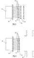
- Figure 4 shows a microlens array 18, sample plate 12 and focussing electrode 22 of a further embodiment of an imaging mass spectrometer according to the invention.
- This figure illustrates one method of focussing the ions produced from the sample plate 12 to ensure that the ions from each defined spot points 20 on the sample plate are kept in separate beams.
- the laser 16 shines through the microlens array 18 onto the back of the sample plate 12 at the predefined spot points 20.
- the ions move away from the plate 12 in a generally perpendicular direction to the plate.
- the grid electrodes 22 focus the ions into beams according to the defined spot 20 on the sample plate 12 that the ions originate from.
- a voltage is provided across the region in which the ions are travelling and is arranged to pulse the ions on their independent paths into a time of flight tube, towards a detector. Ions will arrive at the detector according to their mass to charge ratio.
- the ions produced from each given point on the sample plate 12 are arranged to hit the detector at the same known point to indicate the defined spot point of origin of the ions.
- Figure 5 shows a microlens array 18, sample plate 12 and focussing electrodes 22 of a further embodiment of an imaging mass spectrometer according to the invention.
- This figure illustrates an alternative method of focussing the ions produced from the sample on the sample plate 12 to ensure that the ions from each defined spot 20 on the sample plate 12 are kept in separate beams according to one aspect of the invention.
- the laser 16 shines through the microlens array 18 onto the back of the sample plate 12 at the predefined spot points 20.
- the ions move away from the plate in a generally perpendicular direction to the plate 12.
- the multiple grid electrodes 22 focus the ions into beams according to the defined spot on the sample plate 12 that the ions originate from.
- a voltage is provided across the region in which the ions are travelling and is arranged to pulse the ions on their independent paths into a time of flight tube, towards a detector. Ions will arrive at the detector according to their mass to charge ratio.
- the ions produced from each given point on the sample plate are arranged to hit the detector at the same known point to indicate the defined spot point of origin of the ions.
- Figure 6 shows a microlens array 18, sample plate 12 and focussing electrode 22 of a further embodiment of an imaging mass spectrometer according to the invention.
- This figure provides an illustration of a further method of focussing the ions produced from the sample plate 12 to ensure that the ions from each defined spot points 20 on the sample plate 12 are kept in separate beams.
- the laser 16 shines through the microlens array 18 onto the back of the sample plate 12 at the defined spot points 20.
- the ions move away from the plate in a generally perpendicular direction to the plate.
- gridless electrodes 30 focus the ions into beams according to the defined spot 20 on the sample plate 12 that the ions originate from.
- a voltage is provided across the region in which the ions are travelling and is arranged to pulse the ions on their independent paths into a time of flight tube, towards a detector. Ions will arrive at the detector according to their mass to charge ratio.
- the ions produced from each given point on the sample plate are arranged to hit the detector at the same known point to indicate the defined spot point of origin of the ions.
- Ionisation may in particular be performed by MALDI ionisation. It would be apparent to a person skilled in the art that the alternative ionisation techniques may be interchangable to perform the invention without undue experimentation or modification of the techniques. Any form of the provision of energy in multiple spatially discreet locations through a sample plate 12 to perform surface desorption and ionisation would be suitable to perform some embodiments of the invention.
- the source of energy may be a laser 16.
- suitable lasers include ND:YAG lasers, CO2 lasers, N2 lasers, solid state lasers and gas lasers.
- a homogeniser in accordance with some embodiments of the invention may be any known homogeniser, examples of suitable homogenisers are known within the art.
- An Example of suitable homogenisers include Edmund optics' Techspec® continuously variable apodizing filters. It would be apparent to the skilled person that many other homogenisers may be suitable for use with the invention.
- a microlens array 18 in accordance with the invention may be a square filled array or an unfilled array.
- suitable arrays for the purposes of this invention may be found from Edmund optic's microlens array range, or similarly from Thorlab's microlens array range.
- the energy source provides pulses of energy to the sample.
- a single energy pulse is split into multiple pulses which are simultaneously provided to the sample.
- the microlens array splits a pulse from the laser into multiple pulses which are simultaneousy incident on the sample.
- the energy source may for example comprise a plurality of lasers.
- the pulses are timed to be incident on the sample substantially simultaneously such that the resulting ions can be pulsed into the flight tube with the same pulse.
- the advantage of homogenising the laser beam to create a uniform intensity of laser beam is that it results in the laser intensity supplied to each spot point 20 on the sample plate 12 being substantially the same. This should allow for relative quantitation to be performed on the sample 14. If the intensities of the laser light were varied between spots it would be substantially more difficult to perform any quantitative analysis of the sample.
- the sample plate 12 may be a transparent plate, envisaged materials for the plate may include, but are not limited to glass, perspex, plastics or silica. In less preferred embodiments, particularly where the source of energy is not a laser, the sample plate may be a metal or a ceramics material.
- the sample plate 12 may be relatively thin, in some embodiments the sample plate 12 may in the range of 0.1 mm to 5 cm. In embodiments of the invention where laser energy is used, the sample plate 12 must be thinner than the focal length of the microlens array 18.
- the sample 14 may be a biological sample, other types of samples may include polymers, paint films and inks.
- the sample 14 may have a matrix upon, or mixed in with the sample.
- the sample will have matrix upon the surface to allow for MALDI ionisation to occur at the time or after desorption of the sample from the sample plate 12 in MALDI ionisation mechanisms.
- One or more grid electrodes 22 are used to focus the ions that are travelling from the sample plate 12 to avoid them diverging on the way to the detector.
- the grid electrodes 22 may be used to act as a pusher for a time of flight tube 24 and subsequent detector 26.
- the sample plate 12 or a sample plate holder may be held at a high voltage, and the first grid electrode 22 also held at the same, high voltage with the second grid electrode 22 held at ground.
- the voltage on the first grid electrode may be dropped to produce a pulse which pushes the ions out of the region containing the grid electrodes 22 into the flight tube 24 and to the detector 26.
- the sample plate 12 or a sample plate holder may be held at a high voltage, and the grid electrode 22 also held at the same, high voltage with the flight tube 24 held at ground.
- the voltage on the grid electrode 22 may be dropped to produce a pulse which pushes the ions out of the region containing the grid electrodes into the flight tube 24 and to the detector 26.
- the apparatus may use a delayed extraction mode of operation to correct for differences in the velocity of ions that are desorbed from the sample plate 12.
- a delay between the timing of the laser pulse and the pulsing of ions out of the ion source into the flight tube 24 is created. It would be apparent to the skilled person that this would allow greater mass resolution for the instrument.
- the analyser is a linear ToF.
- the time of flight analyser is a reflectron ToF.
- the detector 26 is a MCP array detector, in one embodiment the MCP array detector has an array of MCPs corresponding to the elements of the microlens array and hence, the spot points 20 on the sample plate 12. In the preferred embodiment each MCP detector will receive ions from it's corresponding spot point 20 on the sample plate 12 to produce a spectrum from each MCP for each corresponding sample spot.
- the detector 26 may be a delay line detector.
- a known delay line detector that may be suitable for use in this embodiment is the Kratos axis nova delay line detector.
- a delay line detector is capable of providing a single pulse counting detector which can give both Flight time data and positional data for any ion which reaches the detector.
- a typical delay line detector comprises a multi-channel plate stack above two orthogonal delay-line anodes and associated electronic control units to deconvolute the information provided by the data to produce imaging information.
- Post Source Decay may be encouraged within analyser, such that both parent and daughter ions may be produced for ions from each spot.
- ions By increasing the laser intensity, ions can be encouraged to decay after ionisation. This can be used to provide daughter ion spectra as well as parent ion spectra from the sample at the same time.
- a reflectron system would be preferred, although a ToF-ToF instrument may also be used.
- a detector 26 may be arranged to detect the position and flight time of the parent ions as previously, but also measure the flight time and position of impact of daughter ions that have been produced by the fragmentation of these parent ions. The position of impact and the time of flight of the daughter ions can be measured, and by deconvolution of the data, a daughter ion mass, and the relative position that daughter ion had originated from may be determined.
- PSD can be performed using a delay line detector. In this instance the precise position can be used to give better positional information for the daughter ions. This may lead to better mass resolution.
- PSD can be performed using a multi array detector
- the laser 16 may be switched between a first low intensity of laser light in a first mode to a second high intensity laser light in a second mode to produce a spectrum of substantially parent ions in said first mode and a spectrum of substantially daughter ions in the second mode.
- the mass spectrometer comprises a sample plate for receiving the sample, and energy is provided through the material of the sample plate.
Description
- The present invention relates to an imaging mass spectrometer and a method of mass spectrometry. More specifically, but not exclusively, the present invention relates to an imaging mass spectrometer which allows multiple spots of a sample to be analyzed at the same time and a method employing such a mass spectrometer.
- It is often useful to know the different compositions of a sample at various different spots across the sample. For example, in the case of biological tissue, this may be a way of identifying areas within the sample which may be responsible for control of different functions for the subject.
- A good way of performing this analysis is often by Matrix Assisted Laser Desorption lonisation (MALDI) imaging, where a user may fire a laser at one spot on the sample on a sample plate, and analyse the ions that are desorbed from that point on the sample. The ions produced may then be analysed by a mass spectrometer to indicate the content of the sample at that point. If one wishes to determine the composition of the whole of the sample then it is typically necessary to make multiple measurements at spaced apart spots. For a large sample this can be time consuming. This is undesirable as there is often competition for time on expensive mass spectrometers. Therefore, any way of reducing the analysis time required for a sample would be advantageous.
- It would therefore be desirable to provide a method of mass spectrometry and a mass spectrometer that is capable of parallel analysis of multiple spots upon a sample, resulting in an increase in sample throughput within the instrument.
-
GB2423187 - Accordingly, the present invention provides an imaging mass spectrometer comprising:
- an energy source adapted to substantially simultaneously provide energy to multiple spots on a sample to produce ions from the sample by a desorption process; and
- an analyser adapted to detect the arrival time and spot origin of ions resulting from said desorption process,
- wherein the imaging mass spectrometer (10) further comprises a sample plate (12) for receiving the sample (14),
- characterised in that:
the energy source is adapted to provide energy on the sample through the sample plate, and at an angle substantially perpendicular to the surface of the sample at each of the respective spots and wherein the imaging mass spectrometer further comprises one or more grid electrodes to focus the ions resulting from the desorption process. - Preferably, the analyser is adapted to detect ions produced by the desorption process.
- Alternatively, or additionally, the analyser is adapted to detect daughter ions produced by the decay of ions produced by the desorption process.
- The energy source can be a laser.
- Desorption of the ions can occur by Matrix Assisted Laser Desorption lonisation.
- The sample plate can be optically transparent.
- The imaging mass spectrometer according to the invention can further comprise a microlens array, the microlens array being adapted to receive the energy from the energy source and provide it at multiple spots on the sample.
- The imaging mass spectrometer can further comprise an homogeniser between the energy source and microlens array.
- The analyser can comprise a TOF.
- The analyser can further comprise a detector for detecting the arrival time and position of ions from the time of flight tube (TOF).
- The detector can comprise an MCP array detector.
- The detector comprises a delay line detector.
- Said analyser can further comprise a reflectron.
- The energy source can be adapted to provide first and second pulses, one of the pulses being a high energy pulse and the other pulse being a low energy pulse.
- The invention also provides a method of imaging mass spectrometry comprising the steps of
providing a sample on a sample plate;
providing energy to multiple spots on the sample substantially simultaneously to produce ions from the sample by a desorption process wherein said energy is provided to the sample through the sample plate, and said energy is provided to said multiple spots at an angle substantially perpendicular to the surface of the sample;
using one or more grid electrodes to focus the ions resulting from the desorption process; and
detecting the arrival time and spot origin of ions resulting from the desorption process. - The step of detecting the arrival time and spot origin can comprise detecting the arrival time and spot origin of ions produced by the desorption process.
- The step of detecting the arrival time and spot origin can comprise detecting the arrival time and spot origin of daughter ions produced by the decay of ions produced by the desorption process.
- The energy can be provided by a laser.
- Preferably, the desorption of ions occurs by Matrix Assisted Laser Desorption lonisation.
- The energy can be provided to the sample through a microlens array.
- Preferably, the step of detecting comprises providing the ions or daughter ions to a TOF and then to a detector.
- The step of providing energy can comprise the steps of providing energy in first and second pulses, one pulse being a low energy pulse and the other pulse being a high energy pulse.
- The present invention will now be described by way of example only and not in any limitative sense with reference to the accompanying drawings in which:
-
Figure 1 shows a schematic view of an embodiment of an imaging mass spectrometer according to the invention; -
Figure 2 shows a microlens array and sample plate of a further embodiment of an imaging mass spectrometer according to the invention; -
Figure 3 shows scheme for the interrogation of the sample plate according to the invention; -
Figure 4 shows a microlens array, sample plate and focussing electrode of a further embodiment of an imaging mass spectrometer according to the invention ; -
Figure 5 shows a microlens array, sample plate and focussing electrode of a further embodiment of an imaging mass spectrometer according to the invention; and -
Figure 6 shows a microlens array, sample plate and focussing electrode of a further embodiment of an imaging mass spectrometer according to the invention - The present invention relates to an apparatus and method for performing Imaging Mass Spectrometry. The methods and devices of the present invention have particular application in the field of MALDI Mass Spectrometry, with the understanding that embodiments of the present invention have utility for performing Imaging mass spectrometry using imaging ion sources other than MALDI.
-
Figure 1 shows a schematic view of animaging mass spectrometer 10 according to the invention. Theimaging mass spectrometer 10 comprises asample plate 12. Asample 14 is arranged on the top surface of the plate. An energy source 16 (in this case a laser) is pulsed to irradiate amicrolens array 18 positioned to the rear of thesample plate 12 to produce an array of focused laser light which passes through the opticallytransparent sample plate 12 and irradiatesdefined spots 20 upon thesample 14. These desorb and ionise ions from the top the surface of thesample 14. The ions then move away from thesample plate 12 in a generally perpendicular direction to theplate 12 into the analyser which detects the spot source and time of arrival of these ions. - The analyser of the mass spectrometer according to the invention comprises a plurality of focussing
electrodes 22. The focussing electrodes are arranged to confine the ions into independent paths according to which defined point on the sample plate they have been desorbed from. - The analyser further comprises a TOF 24 (Time Of Flight Tube) and a
detector 26. At a predefined time after the laser was pulsed, a voltage is provided across the region in which the ions are travelling and is arranged to pulse the ions on their independent paths into the TOF, The ions which exit the TOF are received by the detector. Ions will arrive at the detector according to their mass to charge ratio. The ions produced from a given spot on the sample all hit the detector at the same known point orregion 28. Ions produced from a different spot on the sample hit the detector at a different point orregion 28. -
Figure 2 shows amicrolens array 18 andsample plate 12 of an imaging mass spectrometer according to the invention. In this embodiment, asample plate 12 is provided with asample substrate 14 placed on the top surface of theplate 12. Alaser 16 is pulsed to irradiate a homogeniser (not shown), placed between thelaser 16 and thesample plate 12 in order to create a uniform light intensity across the laser beam. The beam then irradiates themicrolens array 18 positioned to the rear of thesample plate 12 to produce an array of focused laser light beams each of the same intensity. These irradiate the sample at a plurality ofspots 20 causing ions to uniformly desorb from the top surface of thesample 14. The analysis of the ions produced by this means would then potentially be similar to that described with relation tofigure 1 . -
Figure 3a-d are illustrations of a scheme for the interrogation of thesample plate 12 according to the invention.Figure 3a shows a view of asuitable microlens array 18 in accordance with the invention looking at it from thesample plate 12. Each element on the array is arranged to focus the laser light shining on the back of it, on to a precise defined spot point on the back of theplate 12 as shown infig 3b , in order to provide ionisation and desorption off the top surface. Thelaser 16 can be fired as many times as desired on the defined spots on thesample plate 12. - After analysing the ions produced from the first defined spot points 20 on the
sample plate 12, thesample plate 12 can be moved to interrogate a second set of spot points 20 on theplate 12. The position of the second spot points 20 is shown infig 3c . They can be analysed in the same way as described for the first spot points. After interrogating the entire sample of interest, an array of acquistions as shown infig 3d can have been performed. -
Figure 4 shows amicrolens array 18,sample plate 12 and focussingelectrode 22 of a further embodiment of an imaging mass spectrometer according to the invention. This figure illustrates one method of focussing the ions produced from thesample plate 12 to ensure that the ions from each defined spot points 20 on the sample plate are kept in separate beams. In the embodiment offigure 4 , thelaser 16 shines through themicrolens array 18 onto the back of thesample plate 12 at the predefined spot points 20. When the sample on thesample plate 12 is desorbed and ionised, the ions move away from theplate 12 in a generally perpendicular direction to the plate. Thegrid electrodes 22 focus the ions into beams according to the definedspot 20 on thesample plate 12 that the ions originate from. - At a predefined time after the
laser 16 was pulsed, a voltage is provided across the region in which the ions are travelling and is arranged to pulse the ions on their independent paths into a time of flight tube, towards a detector. Ions will arrive at the detector according to their mass to charge ratio. The ions produced from each given point on thesample plate 12 are arranged to hit the detector at the same known point to indicate the defined spot point of origin of the ions. -
Figure 5 shows amicrolens array 18,sample plate 12 and focussingelectrodes 22 of a further embodiment of an imaging mass spectrometer according to the invention. This figure illustrates an alternative method of focussing the ions produced from the sample on thesample plate 12 to ensure that the ions from each definedspot 20 on thesample plate 12 are kept in separate beams according to one aspect of the invention. Infigure 5 , thelaser 16 shines through themicrolens array 18 onto the back of thesample plate 12 at the predefined spot points 20. When the sample on thesample plate 12 is desorbed and ionised, the ions move away from the plate in a generally perpendicular direction to theplate 12. In this embodiment, themultiple grid electrodes 22 focus the ions into beams according to the defined spot on thesample plate 12 that the ions originate from. - At a predefined time after the
laser 16 was pulsed, a voltage is provided across the region in which the ions are travelling and is arranged to pulse the ions on their independent paths into a time of flight tube, towards a detector. Ions will arrive at the detector according to their mass to charge ratio. The ions produced from each given point on the sample plate are arranged to hit the detector at the same known point to indicate the defined spot point of origin of the ions. -
Figure 6 shows amicrolens array 18,sample plate 12 and focussingelectrode 22 of a further embodiment of an imaging mass spectrometer according to the invention. This figure provides an illustration of a further method of focussing the ions produced from thesample plate 12 to ensure that the ions from each defined spot points 20 on thesample plate 12 are kept in separate beams. Infigure 6 , thelaser 16 shines through themicrolens array 18 onto the back of thesample plate 12 at the defined spot points 20. When the sample14 on thesample plate 12 is desorbed and ionised, the ions move away from the plate in a generally perpendicular direction to the plate. In this embodiment,gridless electrodes 30 focus the ions into beams according to the definedspot 20 on thesample plate 12 that the ions originate from. - At a predefined time after the
laser 16 was pulsed, a voltage is provided across the region in which the ions are travelling and is arranged to pulse the ions on their independent paths into a time of flight tube, towards a detector. Ions will arrive at the detector according to their mass to charge ratio. The ions produced from each given point on the sample plate are arranged to hit the detector at the same known point to indicate the defined spot point of origin of the ions. - Ionisation may in particular be performed by MALDI ionisation. It would be apparent to a person skilled in the art that the alternative ionisation techniques may be interchangable to perform the invention without undue experimentation or modification of the techniques. Any form of the provision of energy in multiple spatially discreet locations through a
sample plate 12 to perform surface desorption and ionisation would be suitable to perform some embodiments of the invention. - In some embodiments the source of energy may be a
laser 16. Examples of suitable lasers include ND:YAG lasers, CO2 lasers, N2 lasers, solid state lasers and gas lasers. - A homogeniser in accordance with some embodiments of the invention may be any known homogeniser, examples of suitable homogenisers are known within the art. An Example of suitable homogenisers include Edmund optics' Techspec® continuously variable apodizing filters. It would be apparent to the skilled person that many other homogenisers may be suitable for use with the invention.
- A
microlens array 18 in accordance with the invention may be a square filled array or an unfilled array. Examples of suitable arrays for the purposes of this invention may be found from Edmund optic's microlens array range, or similarly from Thorlab's microlens array range. - Typically the energy source provides pulses of energy to the sample. A single energy pulse is split into multiple pulses which are simultaneously provided to the sample. In the preferred embodiment where the energy source is a laser the microlens array splits a pulse from the laser into multiple pulses which are simultaneousy incident on the sample.
- In alternative embodiments of the invention the energy source may for example comprise a plurality of lasers. In such embodiments the pulses are timed to be incident on the sample substantially simultaneously such that the resulting ions can be pulsed into the flight tube with the same pulse.
- The advantage of homogenising the laser beam to create a uniform intensity of laser beam is that it results in the laser intensity supplied to each
spot point 20 on thesample plate 12 being substantially the same. This should allow for relative quantitation to be performed on thesample 14. If the intensities of the laser light were varied between spots it would be substantially more difficult to perform any quantitative analysis of the sample. - In some embodiments of the invention the
sample plate 12 may be a transparent plate, envisaged materials for the plate may include, but are not limited to glass, perspex, plastics or silica. In less preferred embodiments, particularly where the source of energy is not a laser, the sample plate may be a metal or a ceramics material. - In some embodiments of the invention the
sample plate 12 may be relatively thin, in some embodiments thesample plate 12 may in the range of 0.1 mm to 5 cm. In embodiments of the invention where laser energy is used, thesample plate 12 must be thinner than the focal length of themicrolens array 18. - In some embodiments the
sample 14 may be a biological sample, other types of samples may include polymers, paint films and inks. - In a preferred embodiment the
sample 14 may have a matrix upon, or mixed in with the sample. In the preferred embodiment the sample will have matrix upon the surface to allow for MALDI ionisation to occur at the time or after desorption of the sample from thesample plate 12 in MALDI ionisation mechanisms. - One or
more grid electrodes 22 are used to focus the ions that are travelling from thesample plate 12 to avoid them diverging on the way to the detector. In some embodiments thegrid electrodes 22 may be used to act as a pusher for a time offlight tube 24 andsubsequent detector 26. - In the embodiment including two
grid electrodes 22, thesample plate 12 or a sample plate holder may be held at a high voltage, and thefirst grid electrode 22 also held at the same, high voltage with thesecond grid electrode 22 held at ground. Upon pushing the ions into the ToF tube, the voltage on the first grid electrode may be dropped to produce a pulse which pushes the ions out of the region containing thegrid electrodes 22 into theflight tube 24 and to thedetector 26. - In the embodiment including one
grid electrode 22, thesample plate 12 or a sample plate holder may be held at a high voltage, and thegrid electrode 22 also held at the same, high voltage with theflight tube 24 held at ground. Upon pushing the ions into theToF tube 24, the voltage on thegrid electrode 22 may be dropped to produce a pulse which pushes the ions out of the region containing the grid electrodes into theflight tube 24 and to thedetector 26. - Preferably the apparatus may use a delayed extraction mode of operation to correct for differences in the velocity of ions that are desorbed from the
sample plate 12. A person skilled in the art would understand this to mean that a delay between the timing of the laser pulse and the pulsing of ions out of the ion source into theflight tube 24 is created. It would be apparent to the skilled person that this would allow greater mass resolution for the instrument. - In one embodiment the analyser is a linear ToF. In a second embodiment the time of flight analyser is a reflectron ToF.
- In one embodiment the
detector 26 is a MCP array detector, in one embodiment the MCP array detector has an array of MCPs corresponding to the elements of the microlens array and hence, the spot points 20 on thesample plate 12. In the preferred embodiment each MCP detector will receive ions from it's correspondingspot point 20 on thesample plate 12 to produce a spectrum from each MCP for each corresponding sample spot. - In a second embodiment the
detector 26 may be a delay line detector. A known delay line detector that may be suitable for use in this embodiment is the Kratos axis nova delay line detector. A delay line detector is capable of providing a single pulse counting detector which can give both Flight time data and positional data for any ion which reaches the detector. A typical delay line detector comprises a multi-channel plate stack above two orthogonal delay-line anodes and associated electronic control units to deconvolute the information provided by the data to produce imaging information. - In a further embodiment of the invention Post Source Decay may be encouraged within analyser, such that both parent and daughter ions may be produced for ions from each spot. By increasing the laser intensity, ions can be encouraged to decay after ionisation. This can be used to provide daughter ion spectra as well as parent ion spectra from the sample at the same time.
- In a PSD enabled embodiment, a reflectron system would be preferred, although a ToF-ToF instrument may also be used.
- In a PSD experiment, in one embodiment a
detector 26 may be arranged to detect the position and flight time of the parent ions as previously, but also measure the flight time and position of impact of daughter ions that have been produced by the fragmentation of these parent ions. The position of impact and the time of flight of the daughter ions can be measured, and by deconvolution of the data, a daughter ion mass, and the relative position that daughter ion had originated from may be determined. - In one embodiment PSD can be performed using a delay line detector. In this instance the precise position can be used to give better positional information for the daughter ions. This may lead to better mass resolution. In a second embodiment PSD can be performed using a multi array detector
- In a further embodiment, the
laser 16 may be switched between a first low intensity of laser light in a first mode to a second high intensity laser light in a second mode to produce a spectrum of substantially parent ions in said first mode and a spectrum of substantially daughter ions in the second mode. - It would be appreciated that the application is drafted to specify MALDI Imaging. It would be appreciated that although the apparatus may be specifically designed to allow the performance of MALDI imaging experiments, a user could perform MALDI without imaging information. Similarly, the imaging function may be disabled using this same apparatus. It would also be appreciated that this invention may apply to different types of ionisation including piezoelectric excitement, Surface enhanced laser desorption (SELDI) and secondary ion mass spectrometry (SIMS).
- The mass spectrometer comprises a sample plate for receiving the sample, and energy is provided through the material of the sample plate.
- Energy is provided through the sample plate to one side of a sample, and the ions are produced from the other side of the sample.
- When used in this specification and claims, the terms "comprises" and "comprising" and variations thereof mean that the specified features, steps or integers are included. The terms are not to be interpreted to exclude the presence of other features, steps or components.
- The features disclosed in the foregoing description, or the following claims, or the accompanying drawings, expressed in their specific forms or in terms of a means for performing the disclosed function, or a method or process for attaining the disclosed result, as appropriate, may, separately, or in any combination of such features, be utilised for realising the invention as defined in the accompanying claims in diverse forms thereof.
Claims (15)
- An imaging mass spectrometer (10) comprising:an energy source (16) adapted to substantially simultaneously provide energy to multiple spots (20) on a sample (14) to produce ions from the sample (14) by a desorption process; andan analyser (24, 26) adapted to detect the arrival time and spot origin of ions resulting from said desorption process,wherein the imaging mass spectrometer (10) further comprises a sample plate (12) for receiving the sample (14),characterised in that:
the energy source (16) is adapted to provide energy on the sample (14) through the sample plate (12), and at an angle substantially perpendicular to the surface of the sample (14) at each of the respective spots (20), and wherein the imaging mass spectrometer (10) further comprises one or more grid electrodes (22) to focus the ions resulting from the desorption process. - An imaging mass spectrometer (10) as claimed in claim 1, wherein the analyser (24, 26) is adapted to detect daughter ions produced by the decay of ions produced by the desorption process.
- An imaging mass spectrometer (10) as claimed in any one of claims 1 to 2, wherein desorption of the ions occurs by Matrix Assisted Laser Desorption lonisation.
- An imaging mass spectrometer (10) as claimed in any one of claims 1 to 3, wherein the sample plate (12) is optically transparent.
- An imaging mass spectrometer (10) as claimed in any one of claims 1 to 4, further comprising a microlens array (18), the microlens array (18) being adapted to receive the energy from the energy source (16) and provide it at multiple spots (20) on the sample (14).
- An imaging mass spectrometer (10) as claimed in any one of claims 1 to 5, wherein the analyser comprises a time of flight tube (TOF) (24).
- An imaging mass spectrometer as claimed in claim 6, wherein the analyser further comprises a detector for detecting the arrival time and position of ions from the TOF.
- An imaging mass spectrometer as claimed in any one of claims 1 to 7, wherein the energy source is adapted to provide first and second pulses, one of the pulses being a high energy pulse and the other pulse being a low energy pulse.
- A method of imaging mass spectrometry comprising the steps of
providing a sample (14) on a sample plate (12);
providing energy to multiple spots (20) on the sample (14) substantially simultaneously to produce ions from the sample (14) by a desorption process wherein said energy is provided to the sample (14) through the sample plate (12), and said energy is provided to said multiple spots (20) at an angle substantially perpendicular to the surface of the sample (14);
using one or more grid electrodes (22) to focus the ions resulting from the desorption process; and
detecting the arrival time and spot origin of ions resulting from the desorption process. - A method as claimed in claim 9, wherein the step of detecting the arrival time and spot origin comprises detecting the arrival time and spot origin of ions produced by the desorption process.
- A method as claimed in either of claims 9 or 10, wherein the step of detecting the arrival time and spot origin comprises detecting the arrival time and spot origin of daughter ions produced by the decay of ions produced by the desorption process.
- A method as claimed in any one of claims 9 to 11, wherein desorption of ions occurs by Matrix Assisted Laser Desorption lonisation.
- A method as claimed in any one of claims 9 to 12, wherein the energy is provided to the sample (14) through a microlens array (18).
- A method as claimed in any one of claims 9 to 13, wherein the step of detecting comprises providing the ions or daughter ions to a TOF and then to a detector.
- A method as claimed in any one of claims 9 to 14, wherein the step of providing energy comprises the steps of providing energy in first and second pulses, one pulse being a low energy pulse and the other pulse being a high energy pulse.
Applications Claiming Priority (2)
| Application Number | Priority Date | Filing Date | Title |
|---|---|---|---|
| GBGB1122309.6A GB201122309D0 (en) | 2011-12-23 | 2011-12-23 | An imaging mass spectrometer and a method of mass spectrometry |
| PCT/GB2012/053215 WO2013093482A2 (en) | 2011-12-23 | 2012-12-20 | An imaging mass spectrometer and a method of mass spectrometry |
Publications (2)
| Publication Number | Publication Date |
|---|---|
| EP2795659A2 EP2795659A2 (en) | 2014-10-29 |
| EP2795659B1 true EP2795659B1 (en) | 2019-12-11 |
Family
ID=45573039
Family Applications (1)
| Application Number | Title | Priority Date | Filing Date |
|---|---|---|---|
| EP12816491.0A Active EP2795659B1 (en) | 2011-12-23 | 2012-12-20 | An imaging mass spectrometer and a method of mass spectrometry |
Country Status (6)
| Country | Link |
|---|---|
| US (1) | US9257268B2 (en) |
| EP (1) | EP2795659B1 (en) |
| JP (1) | JP2015506537A (en) |
| CA (1) | CA2860126A1 (en) |
| GB (1) | GB201122309D0 (en) |
| WO (1) | WO2013093482A2 (en) |
Families Citing this family (22)
| Publication number | Priority date | Publication date | Assignee | Title |
|---|---|---|---|---|
| DE102013018496B4 (en) * | 2013-11-04 | 2016-04-28 | Bruker Daltonik Gmbh | Mass spectrometer with laser spot pattern for MALDI |
| GB201507363D0 (en) | 2015-04-30 | 2015-06-17 | Micromass Uk Ltd And Leco Corp | Multi-reflecting TOF mass spectrometer |
| GB201520130D0 (en) * | 2015-11-16 | 2015-12-30 | Micromass Uk Ltd And Leco Corp | Imaging mass spectrometer |
| GB201520134D0 (en) * | 2015-11-16 | 2015-12-30 | Micromass Uk Ltd And Leco Corp | Imaging mass spectrometer |
| GB201520540D0 (en) | 2015-11-23 | 2016-01-06 | Micromass Uk Ltd And Leco Corp | Improved ion mirror and ion-optical lens for imaging |
| GB201613988D0 (en) | 2016-08-16 | 2016-09-28 | Micromass Uk Ltd And Leco Corp | Mass analyser having extended flight path |
| GB2567794B (en) | 2017-05-05 | 2023-03-08 | Micromass Ltd | Multi-reflecting time-of-flight mass spectrometers |
| GB2563571B (en) | 2017-05-26 | 2023-05-24 | Micromass Ltd | Time of flight mass analyser with spatial focussing |
| US11211238B2 (en) | 2017-08-06 | 2021-12-28 | Micromass Uk Limited | Multi-pass mass spectrometer |
| WO2019030471A1 (en) | 2017-08-06 | 2019-02-14 | Anatoly Verenchikov | Ion guide within pulsed converters |
| EP3662502A1 (en) | 2017-08-06 | 2020-06-10 | Micromass UK Limited | Printed circuit ion mirror with compensation |
| WO2019030477A1 (en) | 2017-08-06 | 2019-02-14 | Anatoly Verenchikov | Accelerator for multi-pass mass spectrometers |
| WO2019030476A1 (en) | 2017-08-06 | 2019-02-14 | Anatoly Verenchikov | Ion injection into multi-pass mass spectrometers |
| US11239067B2 (en) | 2017-08-06 | 2022-02-01 | Micromass Uk Limited | Ion mirror for multi-reflecting mass spectrometers |
| WO2019030473A1 (en) | 2017-08-06 | 2019-02-14 | Anatoly Verenchikov | Fields for multi-reflecting tof ms |
| GB201806507D0 (en) | 2018-04-20 | 2018-06-06 | Verenchikov Anatoly | Gridless ion mirrors with smooth fields |
| LU100773B1 (en) * | 2018-04-24 | 2019-10-24 | Luxembourg Inst Science & Tech List | Multiple beam secondary ion mass spectometry device |
| GB201807605D0 (en) | 2018-05-10 | 2018-06-27 | Micromass Ltd | Multi-reflecting time of flight mass analyser |
| GB201807626D0 (en) | 2018-05-10 | 2018-06-27 | Micromass Ltd | Multi-reflecting time of flight mass analyser |
| GB201808530D0 (en) | 2018-05-24 | 2018-07-11 | Verenchikov Anatoly | TOF MS detection system with improved dynamic range |
| GB201810573D0 (en) | 2018-06-28 | 2018-08-15 | Verenchikov Anatoly | Multi-pass mass spectrometer with improved duty cycle |
| GB201901411D0 (en) | 2019-02-01 | 2019-03-20 | Micromass Ltd | Electrode assembly for mass spectrometer |
Citations (7)
| Publication number | Priority date | Publication date | Assignee | Title |
|---|---|---|---|---|
| US3813544A (en) * | 1971-08-18 | 1974-05-28 | E Remy | Method for evaporating, destroying, exciting and/or ionizing specimen material limited to micro-regions, and arrangement for carrying out this method |
| US4204117A (en) * | 1977-09-03 | 1980-05-20 | Leybold-Heraeus Gmbh | Sample analyzer |
| DE3221681A1 (en) * | 1982-06-08 | 1983-12-08 | Bayer Ag, 5090 Leverkusen | Mass spectrometer with an external sample holder |
| US20030222212A1 (en) * | 2002-05-31 | 2003-12-04 | Beck Kenneth M. | High spatial resolution matrix assisted laser desorption/ionization (maldi) |
| US7180058B1 (en) * | 2005-10-05 | 2007-02-20 | Thermo Finnigan Llc | LDI/MALDI source for enhanced spatial resolution |
| US20090272890A1 (en) * | 2006-05-30 | 2009-11-05 | Shimadzu Corporation | Mass spectrometer |
| US20110139973A1 (en) * | 2008-07-17 | 2011-06-16 | Kratos Analytical Limited | Tof mass spectrometer for stigmatic imaging and associated method |
Family Cites Families (15)
| Publication number | Priority date | Publication date | Assignee | Title |
|---|---|---|---|---|
| US3819941A (en) | 1973-10-15 | 1974-06-25 | Bendix Corp | Mass dependent ion microscope having an array of small mass filters |
| JPH0945276A (en) * | 1995-07-27 | 1997-02-14 | Hitachi Ltd | Mass spectrometer |
| US5654545A (en) * | 1995-09-19 | 1997-08-05 | Bruker-Franzen Analytik Gmbh | Mass resolution in time-of-flight mass spectrometers with reflectors |
| US5777324A (en) * | 1996-09-19 | 1998-07-07 | Sequenom, Inc. | Method and apparatus for maldi analysis |
| JPH10153579A (en) * | 1996-11-21 | 1998-06-09 | Hitachi Ltd | Method and apparatus for analysis of sample |
| SE0002066D0 (en) * | 2000-05-31 | 2000-05-31 | Amersham Pharm Biotech Ab | Method and device for preforming are analyzed in parallel |
| JP2002116184A (en) * | 2000-10-10 | 2002-04-19 | Hitachi Ltd | Instrument and system for analyzing foreign matter in semiconductor device |
| JP2003270208A (en) * | 2002-03-14 | 2003-09-25 | Tdk Corp | Sample holder, apparatus and method for laser ablation and for analyzing sample, and holding base for sample holder |
| JP2005024332A (en) * | 2003-06-30 | 2005-01-27 | Tdk Corp | Laser ablation method, sample analysis method, binder for analysis and manufacturing method of powder processed material |
| US20080020474A1 (en) * | 2004-03-30 | 2008-01-24 | Riken | Method of Analyzing Biosample by Laser Ablation and Apparatus Therefor |
| GB2423187B (en) | 2005-02-10 | 2010-10-27 | Bruker Daltonik Gmbh | Laser system for the ionization of a sample by matrix-assisted laser desorption in mass spectrometric analysis |
| GB0512411D0 (en) * | 2005-06-17 | 2005-07-27 | Polaron Plc | Atom probe |
| US7872223B2 (en) * | 2006-04-07 | 2011-01-18 | Shimadzu Corporation | Mass spectrometer |
| JP5403509B2 (en) * | 2009-04-17 | 2014-01-29 | 国立大学法人大阪大学 | Ion source and mass spectrometer |
| KR101041369B1 (en) | 2009-11-19 | 2011-06-15 | 한국기초과학지원연구원 | High throughput apparatus and method for multiple sample analysis |
-
2011
- 2011-12-23 GB GBGB1122309.6A patent/GB201122309D0/en not_active Ceased
-
2012
- 2012-12-20 WO PCT/GB2012/053215 patent/WO2013093482A2/en active Application Filing
- 2012-12-20 CA CA2860126A patent/CA2860126A1/en not_active Abandoned
- 2012-12-20 US US14/366,903 patent/US9257268B2/en active Active
- 2012-12-20 JP JP2014548194A patent/JP2015506537A/en active Pending
- 2012-12-20 EP EP12816491.0A patent/EP2795659B1/en active Active
Patent Citations (7)
| Publication number | Priority date | Publication date | Assignee | Title |
|---|---|---|---|---|
| US3813544A (en) * | 1971-08-18 | 1974-05-28 | E Remy | Method for evaporating, destroying, exciting and/or ionizing specimen material limited to micro-regions, and arrangement for carrying out this method |
| US4204117A (en) * | 1977-09-03 | 1980-05-20 | Leybold-Heraeus Gmbh | Sample analyzer |
| DE3221681A1 (en) * | 1982-06-08 | 1983-12-08 | Bayer Ag, 5090 Leverkusen | Mass spectrometer with an external sample holder |
| US20030222212A1 (en) * | 2002-05-31 | 2003-12-04 | Beck Kenneth M. | High spatial resolution matrix assisted laser desorption/ionization (maldi) |
| US7180058B1 (en) * | 2005-10-05 | 2007-02-20 | Thermo Finnigan Llc | LDI/MALDI source for enhanced spatial resolution |
| US20090272890A1 (en) * | 2006-05-30 | 2009-11-05 | Shimadzu Corporation | Mass spectrometer |
| US20110139973A1 (en) * | 2008-07-17 | 2011-06-16 | Kratos Analytical Limited | Tof mass spectrometer for stigmatic imaging and associated method |
Also Published As
| Publication number | Publication date |
|---|---|
| US20140361162A1 (en) | 2014-12-11 |
| GB201122309D0 (en) | 2012-02-01 |
| JP2015506537A (en) | 2015-03-02 |
| EP2795659A2 (en) | 2014-10-29 |
| WO2013093482A2 (en) | 2013-06-27 |
| CA2860126A1 (en) | 2013-06-27 |
| WO2013093482A3 (en) | 2013-11-28 |
| US9257268B2 (en) | 2016-02-09 |
Similar Documents
| Publication | Publication Date | Title |
|---|---|---|
| EP2795659B1 (en) | An imaging mass spectrometer and a method of mass spectrometry | |
| EP0827629B1 (en) | Analysis of biomolecules using time-of-flight mass spectrometry | |
| US8581179B2 (en) | Protein sequencing with MALDI mass spectrometry | |
| US6933497B2 (en) | Time-of-flight mass analyzer with multiple flight paths | |
| US6281493B1 (en) | Time-of-flight mass spectrometry analysis of biomolecules | |
| US8558168B2 (en) | Post-ionization of neutrals for ion mobility oTOFMS identification of molecules and elements desorbed from surfaces | |
| US20090039282A1 (en) | Matrix-assisted laser desorption with high ionization yield | |
| JP2006134893A (en) | Tandem mass spectrometry | |
| JP2006511912A5 (en) | ||
| JP2015506537A5 (en) | ||
| US8648295B2 (en) | Combined distance-of-flight and time-of-flight mass spectrometer | |
| US20100181473A1 (en) | Method and apparatus for the analysis of samples | |
| US9627190B2 (en) | Energy resolved time-of-flight mass spectrometry | |
| EP2325864A1 (en) | High throughput apparatus and method for multiple sample analysis | |
| US8110795B2 (en) | Laser system for MALDI mass spectrometry | |
| US7910878B2 (en) | Method and apparatus for ion axial spatial distribution focusing | |
| GB2468394A (en) | Pulsed laser system for MALDI mass spectrometry | |
| GB2453407A (en) | Matrix-assisted laser desorption with high ionization yield | |
| Bush et al. | Chapter 1: Introduction |
Legal Events
| Date | Code | Title | Description |
|---|---|---|---|
| PUAI | Public reference made under article 153(3) epc to a published international application that has entered the european phase |
Free format text: ORIGINAL CODE: 0009012 |
|
| 17P | Request for examination filed |
Effective date: 20140519 |
|
| AK | Designated contracting states |
Kind code of ref document: A2 Designated state(s): AL AT BE BG CH CY CZ DE DK EE ES FI FR GB GR HR HU IE IS IT LI LT LU LV MC MK MT NL NO PL PT RO RS SE SI SK SM TR |
|
| DAX | Request for extension of the european patent (deleted) | ||
| STAA | Information on the status of an ep patent application or granted ep patent |
Free format text: STATUS: EXAMINATION IS IN PROGRESS |
|
| 17Q | First examination report despatched |
Effective date: 20170306 |
|
| GRAP | Despatch of communication of intention to grant a patent |
Free format text: ORIGINAL CODE: EPIDOSNIGR1 |
|
| STAA | Information on the status of an ep patent application or granted ep patent |
Free format text: STATUS: GRANT OF PATENT IS INTENDED |
|
| RIC1 | Information provided on ipc code assigned before grant |
Ipc: H01J 49/16 20060101ALI20190704BHEP Ipc: H01J 49/40 20060101ALI20190704BHEP Ipc: H01J 49/04 20060101ALI20190704BHEP Ipc: H01J 49/00 20060101AFI20190704BHEP |
|
| INTG | Intention to grant announced |
Effective date: 20190724 |
|
| GRAS | Grant fee paid |
Free format text: ORIGINAL CODE: EPIDOSNIGR3 |
|
| GRAA | (expected) grant |
Free format text: ORIGINAL CODE: 0009210 |
|
| STAA | Information on the status of an ep patent application or granted ep patent |
Free format text: STATUS: THE PATENT HAS BEEN GRANTED |
|
| AK | Designated contracting states |
Kind code of ref document: B1 Designated state(s): AL AT BE BG CH CY CZ DE DK EE ES FI FR GB GR HR HU IE IS IT LI LT LU LV MC MK MT NL NO PL PT RO RS SE SI SK SM TR |
|
| REG | Reference to a national code |
Ref country code: GB Ref legal event code: FG4D |
|
| REG | Reference to a national code |
Ref country code: CH Ref legal event code: EP |
|
| REG | Reference to a national code |
Ref country code: AT Ref legal event code: REF Ref document number: 1213033 Country of ref document: AT Kind code of ref document: T Effective date: 20191215 |
|
| REG | Reference to a national code |
Ref country code: DE Ref legal event code: R096 Ref document number: 602012066433 Country of ref document: DE |
|
| REG | Reference to a national code |
Ref country code: IE Ref legal event code: FG4D |
|
| REG | Reference to a national code |
Ref country code: NL Ref legal event code: MP Effective date: 20191211 |
|
| REG | Reference to a national code |
Ref country code: LT Ref legal event code: MG4D |
|
| PG25 | Lapsed in a contracting state [announced via postgrant information from national office to epo] |
Ref country code: GR Free format text: LAPSE BECAUSE OF FAILURE TO SUBMIT A TRANSLATION OF THE DESCRIPTION OR TO PAY THE FEE WITHIN THE PRESCRIBED TIME-LIMIT Effective date: 20200312 Ref country code: LT Free format text: LAPSE BECAUSE OF FAILURE TO SUBMIT A TRANSLATION OF THE DESCRIPTION OR TO PAY THE FEE WITHIN THE PRESCRIBED TIME-LIMIT Effective date: 20191211 Ref country code: BG Free format text: LAPSE BECAUSE OF FAILURE TO SUBMIT A TRANSLATION OF THE DESCRIPTION OR TO PAY THE FEE WITHIN THE PRESCRIBED TIME-LIMIT Effective date: 20200311 Ref country code: FI Free format text: LAPSE BECAUSE OF FAILURE TO SUBMIT A TRANSLATION OF THE DESCRIPTION OR TO PAY THE FEE WITHIN THE PRESCRIBED TIME-LIMIT Effective date: 20191211 Ref country code: ES Free format text: LAPSE BECAUSE OF FAILURE TO SUBMIT A TRANSLATION OF THE DESCRIPTION OR TO PAY THE FEE WITHIN THE PRESCRIBED TIME-LIMIT Effective date: 20191211 Ref country code: LV Free format text: LAPSE BECAUSE OF FAILURE TO SUBMIT A TRANSLATION OF THE DESCRIPTION OR TO PAY THE FEE WITHIN THE PRESCRIBED TIME-LIMIT Effective date: 20191211 Ref country code: SE Free format text: LAPSE BECAUSE OF FAILURE TO SUBMIT A TRANSLATION OF THE DESCRIPTION OR TO PAY THE FEE WITHIN THE PRESCRIBED TIME-LIMIT Effective date: 20191211 Ref country code: NO Free format text: LAPSE BECAUSE OF FAILURE TO SUBMIT A TRANSLATION OF THE DESCRIPTION OR TO PAY THE FEE WITHIN THE PRESCRIBED TIME-LIMIT Effective date: 20200311 |
|
| PG25 | Lapsed in a contracting state [announced via postgrant information from national office to epo] |
Ref country code: HR Free format text: LAPSE BECAUSE OF FAILURE TO SUBMIT A TRANSLATION OF THE DESCRIPTION OR TO PAY THE FEE WITHIN THE PRESCRIBED TIME-LIMIT Effective date: 20191211 Ref country code: RS Free format text: LAPSE BECAUSE OF FAILURE TO SUBMIT A TRANSLATION OF THE DESCRIPTION OR TO PAY THE FEE WITHIN THE PRESCRIBED TIME-LIMIT Effective date: 20191211 |
|
| PG25 | Lapsed in a contracting state [announced via postgrant information from national office to epo] |
Ref country code: AL Free format text: LAPSE BECAUSE OF FAILURE TO SUBMIT A TRANSLATION OF THE DESCRIPTION OR TO PAY THE FEE WITHIN THE PRESCRIBED TIME-LIMIT Effective date: 20191211 |
|
| PG25 | Lapsed in a contracting state [announced via postgrant information from national office to epo] |
Ref country code: NL Free format text: LAPSE BECAUSE OF FAILURE TO SUBMIT A TRANSLATION OF THE DESCRIPTION OR TO PAY THE FEE WITHIN THE PRESCRIBED TIME-LIMIT Effective date: 20191211 Ref country code: CZ Free format text: LAPSE BECAUSE OF FAILURE TO SUBMIT A TRANSLATION OF THE DESCRIPTION OR TO PAY THE FEE WITHIN THE PRESCRIBED TIME-LIMIT Effective date: 20191211 Ref country code: PT Free format text: LAPSE BECAUSE OF FAILURE TO SUBMIT A TRANSLATION OF THE DESCRIPTION OR TO PAY THE FEE WITHIN THE PRESCRIBED TIME-LIMIT Effective date: 20200506 Ref country code: RO Free format text: LAPSE BECAUSE OF FAILURE TO SUBMIT A TRANSLATION OF THE DESCRIPTION OR TO PAY THE FEE WITHIN THE PRESCRIBED TIME-LIMIT Effective date: 20191211 Ref country code: EE Free format text: LAPSE BECAUSE OF FAILURE TO SUBMIT A TRANSLATION OF THE DESCRIPTION OR TO PAY THE FEE WITHIN THE PRESCRIBED TIME-LIMIT Effective date: 20191211 |
|
| REG | Reference to a national code |
Ref country code: CH Ref legal event code: PL |
|
| REG | Reference to a national code |
Ref country code: BE Ref legal event code: MM Effective date: 20191231 |
|
| PG25 | Lapsed in a contracting state [announced via postgrant information from national office to epo] |
Ref country code: IS Free format text: LAPSE BECAUSE OF FAILURE TO SUBMIT A TRANSLATION OF THE DESCRIPTION OR TO PAY THE FEE WITHIN THE PRESCRIBED TIME-LIMIT Effective date: 20200411 Ref country code: SK Free format text: LAPSE BECAUSE OF FAILURE TO SUBMIT A TRANSLATION OF THE DESCRIPTION OR TO PAY THE FEE WITHIN THE PRESCRIBED TIME-LIMIT Effective date: 20191211 Ref country code: SM Free format text: LAPSE BECAUSE OF FAILURE TO SUBMIT A TRANSLATION OF THE DESCRIPTION OR TO PAY THE FEE WITHIN THE PRESCRIBED TIME-LIMIT Effective date: 20191211 |
|
| REG | Reference to a national code |
Ref country code: DE Ref legal event code: R097 Ref document number: 602012066433 Country of ref document: DE |
|
| PG25 | Lapsed in a contracting state [announced via postgrant information from national office to epo] |
Ref country code: MC Free format text: LAPSE BECAUSE OF FAILURE TO SUBMIT A TRANSLATION OF THE DESCRIPTION OR TO PAY THE FEE WITHIN THE PRESCRIBED TIME-LIMIT Effective date: 20191211 |
|
| REG | Reference to a national code |
Ref country code: AT Ref legal event code: MK05 Ref document number: 1213033 Country of ref document: AT Kind code of ref document: T Effective date: 20191211 |
|
| PLBE | No opposition filed within time limit |
Free format text: ORIGINAL CODE: 0009261 |
|
| STAA | Information on the status of an ep patent application or granted ep patent |
Free format text: STATUS: NO OPPOSITION FILED WITHIN TIME LIMIT |
|
| PG25 | Lapsed in a contracting state [announced via postgrant information from national office to epo] |
Ref country code: DK Free format text: LAPSE BECAUSE OF FAILURE TO SUBMIT A TRANSLATION OF THE DESCRIPTION OR TO PAY THE FEE WITHIN THE PRESCRIBED TIME-LIMIT Effective date: 20191211 Ref country code: IE Free format text: LAPSE BECAUSE OF NON-PAYMENT OF DUE FEES Effective date: 20191220 Ref country code: LU Free format text: LAPSE BECAUSE OF NON-PAYMENT OF DUE FEES Effective date: 20191220 |
|
| 26N | No opposition filed |
Effective date: 20200914 |
|
| PG25 | Lapsed in a contracting state [announced via postgrant information from national office to epo] |
Ref country code: AT Free format text: LAPSE BECAUSE OF FAILURE TO SUBMIT A TRANSLATION OF THE DESCRIPTION OR TO PAY THE FEE WITHIN THE PRESCRIBED TIME-LIMIT Effective date: 20191211 Ref country code: PL Free format text: LAPSE BECAUSE OF FAILURE TO SUBMIT A TRANSLATION OF THE DESCRIPTION OR TO PAY THE FEE WITHIN THE PRESCRIBED TIME-LIMIT Effective date: 20191211 Ref country code: LI Free format text: LAPSE BECAUSE OF NON-PAYMENT OF DUE FEES Effective date: 20191231 Ref country code: SI Free format text: LAPSE BECAUSE OF FAILURE TO SUBMIT A TRANSLATION OF THE DESCRIPTION OR TO PAY THE FEE WITHIN THE PRESCRIBED TIME-LIMIT Effective date: 20191211 Ref country code: CH Free format text: LAPSE BECAUSE OF NON-PAYMENT OF DUE FEES Effective date: 20191231 Ref country code: BE Free format text: LAPSE BECAUSE OF NON-PAYMENT OF DUE FEES Effective date: 20191231 |
|
| PG25 | Lapsed in a contracting state [announced via postgrant information from national office to epo] |
Ref country code: IT Free format text: LAPSE BECAUSE OF FAILURE TO SUBMIT A TRANSLATION OF THE DESCRIPTION OR TO PAY THE FEE WITHIN THE PRESCRIBED TIME-LIMIT Effective date: 20191211 Ref country code: FR Free format text: LAPSE BECAUSE OF NON-PAYMENT OF DUE FEES Effective date: 20200211 |
|
| PG25 | Lapsed in a contracting state [announced via postgrant information from national office to epo] |
Ref country code: CY Free format text: LAPSE BECAUSE OF FAILURE TO SUBMIT A TRANSLATION OF THE DESCRIPTION OR TO PAY THE FEE WITHIN THE PRESCRIBED TIME-LIMIT Effective date: 20191211 |
|
| PG25 | Lapsed in a contracting state [announced via postgrant information from national office to epo] |
Ref country code: MT Free format text: LAPSE BECAUSE OF FAILURE TO SUBMIT A TRANSLATION OF THE DESCRIPTION OR TO PAY THE FEE WITHIN THE PRESCRIBED TIME-LIMIT Effective date: 20191211 Ref country code: HU Free format text: LAPSE BECAUSE OF FAILURE TO SUBMIT A TRANSLATION OF THE DESCRIPTION OR TO PAY THE FEE WITHIN THE PRESCRIBED TIME-LIMIT; INVALID AB INITIO Effective date: 20121220 |
|
| PG25 | Lapsed in a contracting state [announced via postgrant information from national office to epo] |
Ref country code: TR Free format text: LAPSE BECAUSE OF FAILURE TO SUBMIT A TRANSLATION OF THE DESCRIPTION OR TO PAY THE FEE WITHIN THE PRESCRIBED TIME-LIMIT Effective date: 20191211 |
|
| PG25 | Lapsed in a contracting state [announced via postgrant information from national office to epo] |
Ref country code: MK Free format text: LAPSE BECAUSE OF FAILURE TO SUBMIT A TRANSLATION OF THE DESCRIPTION OR TO PAY THE FEE WITHIN THE PRESCRIBED TIME-LIMIT Effective date: 20191211 |
|
| REG | Reference to a national code |
Ref country code: DE Ref legal event code: R082 Ref document number: 602012066433 Country of ref document: DE Representative=s name: FORRESTERS IP LLP, DE Ref country code: DE Ref legal event code: R082 Ref document number: 602012066433 Country of ref document: DE Representative=s name: KUEHR, VERA, DIPL.-BIOL., DE |
|
| P01 | Opt-out of the competence of the unified patent court (upc) registered |
Effective date: 20230609 |
|
| P02 | Opt-out of the competence of the unified patent court (upc) changed |
Effective date: 20230619 |
|
| REG | Reference to a national code |
Ref country code: DE Ref legal event code: R082 Ref document number: 602012066433 Country of ref document: DE Representative=s name: FORRESTERS IP LLP, DE |
|
| PGFP | Annual fee paid to national office [announced via postgrant information from national office to epo] |
Ref country code: GB Payment date: 20231124 Year of fee payment: 12 |
|
| PGFP | Annual fee paid to national office [announced via postgrant information from national office to epo] |
Ref country code: DE Payment date: 20231121 Year of fee payment: 12 |