EP2795065B1 - Connector - Google Patents
Connector Download PDFInfo
- Publication number
- EP2795065B1 EP2795065B1 EP12809313.5A EP12809313A EP2795065B1 EP 2795065 B1 EP2795065 B1 EP 2795065B1 EP 12809313 A EP12809313 A EP 12809313A EP 2795065 B1 EP2795065 B1 EP 2795065B1
- Authority
- EP
- European Patent Office
- Prior art keywords
- connector
- impeller
- shaft
- hub extension
- sleeve portion
- Prior art date
- Legal status (The legal status is an assumption and is not a legal conclusion. Google has not performed a legal analysis and makes no representation as to the accuracy of the status listed.)
- Active
Links
- 239000000463 material Substances 0.000 claims description 11
- 230000004323 axial length Effects 0.000 claims description 8
- 230000015572 biosynthetic process Effects 0.000 claims description 3
- 229910052751 metal Inorganic materials 0.000 claims description 3
- 239000002184 metal Substances 0.000 claims description 3
- 229910000831 Steel Inorganic materials 0.000 description 16
- 239000010959 steel Substances 0.000 description 16
- 238000007789 sealing Methods 0.000 description 11
- 239000004411 aluminium Substances 0.000 description 9
- XAGFODPZIPBFFR-UHFFFAOYSA-N aluminium Chemical compound [Al] XAGFODPZIPBFFR-UHFFFAOYSA-N 0.000 description 9
- 229910052782 aluminium Inorganic materials 0.000 description 9
- 238000003780 insertion Methods 0.000 description 8
- 230000037431 insertion Effects 0.000 description 8
- 229910000838 Al alloy Inorganic materials 0.000 description 5
- PXHVJJICTQNCMI-UHFFFAOYSA-N Nickel Chemical compound [Ni] PXHVJJICTQNCMI-UHFFFAOYSA-N 0.000 description 4
- 239000003921 oil Substances 0.000 description 3
- IJGRMHOSHXDMSA-UHFFFAOYSA-N Atomic nitrogen Chemical compound N#N IJGRMHOSHXDMSA-UHFFFAOYSA-N 0.000 description 2
- XEEYBQQBJWHFJM-UHFFFAOYSA-N Iron Chemical compound [Fe] XEEYBQQBJWHFJM-UHFFFAOYSA-N 0.000 description 2
- 238000005755 formation reaction Methods 0.000 description 2
- 238000010438 heat treatment Methods 0.000 description 2
- 238000000034 method Methods 0.000 description 2
- 239000000203 mixture Substances 0.000 description 2
- 229910052759 nickel Inorganic materials 0.000 description 2
- 230000008646 thermal stress Effects 0.000 description 2
- 101100058324 Arabidopsis thaliana BHLH19 gene Proteins 0.000 description 1
- RYGMFSIKBFXOCR-UHFFFAOYSA-N Copper Chemical compound [Cu] RYGMFSIKBFXOCR-UHFFFAOYSA-N 0.000 description 1
- FYYHWMGAXLPEAU-UHFFFAOYSA-N Magnesium Chemical compound [Mg] FYYHWMGAXLPEAU-UHFFFAOYSA-N 0.000 description 1
- 230000032683 aging Effects 0.000 description 1
- 229910045601 alloy Inorganic materials 0.000 description 1
- 239000000956 alloy Substances 0.000 description 1
- 238000001816 cooling Methods 0.000 description 1
- 229910052802 copper Inorganic materials 0.000 description 1
- 239000010949 copper Substances 0.000 description 1
- 125000004122 cyclic group Chemical group 0.000 description 1
- 230000001351 cycling effect Effects 0.000 description 1
- 230000000694 effects Effects 0.000 description 1
- 238000007689 inspection Methods 0.000 description 1
- 229910052742 iron Inorganic materials 0.000 description 1
- 239000007788 liquid Substances 0.000 description 1
- 239000010687 lubricating oil Substances 0.000 description 1
- 229910052749 magnesium Inorganic materials 0.000 description 1
- 239000011777 magnesium Substances 0.000 description 1
- 238000004519 manufacturing process Methods 0.000 description 1
- 150000002739 metals Chemical class 0.000 description 1
- 238000012986 modification Methods 0.000 description 1
- 230000004048 modification Effects 0.000 description 1
- 229910052757 nitrogen Inorganic materials 0.000 description 1
- 230000000630 rising effect Effects 0.000 description 1
- 230000035882 stress Effects 0.000 description 1
Images
Classifications
-
- F—MECHANICAL ENGINEERING; LIGHTING; HEATING; WEAPONS; BLASTING
- F01—MACHINES OR ENGINES IN GENERAL; ENGINE PLANTS IN GENERAL; STEAM ENGINES
- F01D—NON-POSITIVE DISPLACEMENT MACHINES OR ENGINES, e.g. STEAM TURBINES
- F01D5/00—Blades; Blade-carrying members; Heating, heat-insulating, cooling or antivibration means on the blades or the members
- F01D5/02—Blade-carrying members, e.g. rotors
- F01D5/025—Fixing blade carrying members on shafts
-
- F—MECHANICAL ENGINEERING; LIGHTING; HEATING; WEAPONS; BLASTING
- F01—MACHINES OR ENGINES IN GENERAL; ENGINE PLANTS IN GENERAL; STEAM ENGINES
- F01D—NON-POSITIVE DISPLACEMENT MACHINES OR ENGINES, e.g. STEAM TURBINES
- F01D5/00—Blades; Blade-carrying members; Heating, heat-insulating, cooling or antivibration means on the blades or the members
- F01D5/02—Blade-carrying members, e.g. rotors
- F01D5/026—Shaft to shaft connections
-
- F—MECHANICAL ENGINEERING; LIGHTING; HEATING; WEAPONS; BLASTING
- F04—POSITIVE - DISPLACEMENT MACHINES FOR LIQUIDS; PUMPS FOR LIQUIDS OR ELASTIC FLUIDS
- F04D—NON-POSITIVE-DISPLACEMENT PUMPS
- F04D29/00—Details, component parts, or accessories
- F04D29/26—Rotors specially for elastic fluids
- F04D29/266—Rotors specially for elastic fluids mounting compressor rotors on shafts
-
- F—MECHANICAL ENGINEERING; LIGHTING; HEATING; WEAPONS; BLASTING
- F16—ENGINEERING ELEMENTS AND UNITS; GENERAL MEASURES FOR PRODUCING AND MAINTAINING EFFECTIVE FUNCTIONING OF MACHINES OR INSTALLATIONS; THERMAL INSULATION IN GENERAL
- F16D—COUPLINGS FOR TRANSMITTING ROTATION; CLUTCHES; BRAKES
- F16D1/00—Couplings for rigidly connecting two coaxial shafts or other movable machine elements
- F16D1/06—Couplings for rigidly connecting two coaxial shafts or other movable machine elements for attachment of a member on a shaft or on a shaft-end
- F16D1/076—Couplings for rigidly connecting two coaxial shafts or other movable machine elements for attachment of a member on a shaft or on a shaft-end by clamping together two faces perpendicular to the axis of rotation, e.g. with bolted flanges
-
- F—MECHANICAL ENGINEERING; LIGHTING; HEATING; WEAPONS; BLASTING
- F16—ENGINEERING ELEMENTS AND UNITS; GENERAL MEASURES FOR PRODUCING AND MAINTAINING EFFECTIVE FUNCTIONING OF MACHINES OR INSTALLATIONS; THERMAL INSULATION IN GENERAL
- F16D—COUPLINGS FOR TRANSMITTING ROTATION; CLUTCHES; BRAKES
- F16D1/00—Couplings for rigidly connecting two coaxial shafts or other movable machine elements
- F16D1/06—Couplings for rigidly connecting two coaxial shafts or other movable machine elements for attachment of a member on a shaft or on a shaft-end
- F16D1/08—Couplings for rigidly connecting two coaxial shafts or other movable machine elements for attachment of a member on a shaft or on a shaft-end with clamping hub; with hub and longitudinal key
- F16D1/0847—Couplings for rigidly connecting two coaxial shafts or other movable machine elements for attachment of a member on a shaft or on a shaft-end with clamping hub; with hub and longitudinal key with radial clamping due to a radial screw
-
- F—MECHANICAL ENGINEERING; LIGHTING; HEATING; WEAPONS; BLASTING
- F16—ENGINEERING ELEMENTS AND UNITS; GENERAL MEASURES FOR PRODUCING AND MAINTAINING EFFECTIVE FUNCTIONING OF MACHINES OR INSTALLATIONS; THERMAL INSULATION IN GENERAL
- F16D—COUPLINGS FOR TRANSMITTING ROTATION; CLUTCHES; BRAKES
- F16D1/00—Couplings for rigidly connecting two coaxial shafts or other movable machine elements
- F16D1/06—Couplings for rigidly connecting two coaxial shafts or other movable machine elements for attachment of a member on a shaft or on a shaft-end
- F16D1/08—Couplings for rigidly connecting two coaxial shafts or other movable machine elements for attachment of a member on a shaft or on a shaft-end with clamping hub; with hub and longitudinal key
- F16D1/0852—Couplings for rigidly connecting two coaxial shafts or other movable machine elements for attachment of a member on a shaft or on a shaft-end with clamping hub; with hub and longitudinal key with radial clamping between the mating surfaces of the hub and shaft
- F16D1/0858—Couplings for rigidly connecting two coaxial shafts or other movable machine elements for attachment of a member on a shaft or on a shaft-end with clamping hub; with hub and longitudinal key with radial clamping between the mating surfaces of the hub and shaft due to the elasticity of the hub (including shrink fits)
-
- F—MECHANICAL ENGINEERING; LIGHTING; HEATING; WEAPONS; BLASTING
- F16—ENGINEERING ELEMENTS AND UNITS; GENERAL MEASURES FOR PRODUCING AND MAINTAINING EFFECTIVE FUNCTIONING OF MACHINES OR INSTALLATIONS; THERMAL INSULATION IN GENERAL
- F16D—COUPLINGS FOR TRANSMITTING ROTATION; CLUTCHES; BRAKES
- F16D2300/00—Special features for couplings or clutches
- F16D2300/08—Details or arrangements of sealings not provided for in group F16D3/84
Definitions
- the present invention relates to a connector for connecting an impeller to a shaft, and in particular, but not exclusively, for connecting an impeller of a turbocharger to a turbocharger shaft.
- Turbocharger impellers are typically made of aluminium alloys to provide low rotational inertia with reasonable strength at a commercially-acceptable cost. Attachment of the impeller to the steel turbocharger shaft is achieved in various ways. For example, because of the relative weakness of aluminium and the small diameter of the shaft, one option is to provide the impeller with a steel insert containing a screw-threaded socket which can be threaded on to the shaft. This arrangement can take a higher torque than a connection in which the shaft is directly threaded into the aluminium body (the torque is proportional to the power transmitted across the joint, and so the impeller can be used at a higher pressure ratio than one in which there is a direct threaded connection).
- such an insert is fitted into the impeller by shrink fitting; the aluminium body of the impeller is heated to expand the bore which is to receive the steel insert, while the insert is cooled, for example using liquid nitrogen, before being inserted into the bore.
- the resultant interference connection is restricted by the temperature to which the aluminium can be heated before its material properties are affected, and by the temperature to which the steel can be cooled.
- the turbocharger then starts to heat up, and because of the different thermal coefficients of expansion of the aluminium alloy and the steel, the aluminium grows axially more than the steel, causing the two metals to slide over each other, except at the location where the impeller still grips the insert firmly. On shutdown, the centrifugal stresses are removed, but the thermal stresses remain for some minutes as the turbocharger cools.
- EP1394387 proposes an outer steel constraining ring which reinforces the frictional contact between aluminium impeller and the insert. Since the ring does not expand as much as the impeller body as the turbocharger heats up, the point of grip between the impeller and the insert remains within the axial extent of the ring during the whole operating cycle of the turbocharger, thereby preventing the tendency of the impeller to "walk" along the insert. As a consequence, the operating life of the turbocharger can be considerably extended in comparison with the conventional turbocharger without the constraining ring.
- US 2005/0232775 proposes a fastening arrangement for an impeller on a shaft.
- the present invention provides a connector for connecting an impeller to a shaft, in particular for connecting an impeller of a turbocharger to a turbocharger shaft, wherein the connector is formed as a unitary body having:
- the connection between the impeller and the shaft can be greatly simplified, e.g. with fewer high precision interfaces.
- the connector is generally formed of a material having a greater strength than the material of the impeller and having a lower coefficient of thermal expansion than the material of the impeller.
- the degree of interference required on fitting the connector to the impeller can be reduced, while maintaining the "walk" resistance and torque capacity of the joint.
- the connector typically does not require an insert which frictionally connects to the hub extension by shrink fitting, heating of the impeller on fitting can be avoided, whereby material properties of the impeller may not be degraded by accelerated ageing during assembly.
- a second aspect of the invention provides an impeller having a shaft-side hub extension and fitted with a connector according to the first aspect, the sleeve portion of the connector being frictionally connected on a radially outer surface of the hub extension.
- a third aspect of the invention provides the impeller fitted with a connector of the second aspect, which impeller is connected to a shaft having a corresponding threaded portion, the thread of the threaded portion of the connector screwing onto the corresponding threaded portion of the shaft.
- a fourth aspect of the invention provides a turbocharger having the connected impeller and shaft of the third aspect.
- the sleeve portion of the connector may be approximately cylindrically shaped.
- the outer surface of the shaft-side hub extension of the impeller may be correspondingly approximately cylindrical.
- the frictional connection between the sleeve portion and the hub extension can be achieved by e.g. by press fitting or shrink fitting.
- the threads can be positive-locking, e.g. tapered.
- the connector can have an abutment surface which engages a corresponding abutment surface of the shaft when the threaded portions are screwed together, thereby tightening the threads to provide the rotationally fixed connection.
- the connector may be configured to contact the impeller only on the radially outer surface of the hub extension.
- the hub extension may have an end face
- the connector may have an abutment portion which bears against the end face.
- the connector may be configured to contact the impeller only on the radially outer surface of the hub extension and the end face of the hub extension.
- the end face is at the radially outer side and impeller end of the hub extension so that "walking" of the impeller can be readily monitored by measuring any gap that opens up between the end face and the abutment portion.
- the frictional connection between the sleeve portion and the radially outer surface of the hub extension transmits, in use, substantially all of the torque between the shaft and the impeller.
- the hub extension may have a central recess, and a part of the connector may be inserted into the recess. However, a clearance may be provided between that part of the connector and the side surface of the recess.
- the connector may not contact the side surface of the recess, i.e. if the connector contacts a surface of the recess at all, it may only contact an end surface of the recess.
- the impeller does not have a through-hole extending from one side to another of the impeller.
- the central recess is a blind hole (with an end face), the hole opening to the shaft-side end face of the hub extension.
- the part of the connector inserted into the recess may include the threaded portion of the connector. In this way, an axially compact arrangement can be achieved.
- the thread of the connector can face radially outwardly.
- the threaded portion of the connector can be formed as a substantially cylindrical boss coaxial with the shaft, and the threads can be formed on a radially outer surface of the boss.
- the thread of the connector can face radially inwardly.
- the threaded portion can be included in the part of the connector inserted into the recess.
- the connector may be formed of a material, such as steel and preferably high tensile steel, having a greater strength than the material (typically metal and more typically aluminium alloy) of the impeller and having a lower coefficient of thermal expansion than the material of the impeller.
- the sleeve portion can extend over at least 50%, and preferably at least 80%, of the axial length of the hub extension. More preferably the sleeve portion can extend over substantially the entire axial length of the hub extension.
- Frictional contact between the sleeve portion and the hub extension can extend over at least 25% of the axial length of the overlap region between the sleeve portion and the hub extension, preferably over at least 30% or 50% of the axial length of the overlap region, and more preferably over the entire axial length of the overlap region.
- the connector and/or the impeller may have one or more centring portions having respective engagement surfaces which engage with one or more corresponding centring portions of the shaft, the threaded portion of the connector and the centring portions of the connector and/or the impeller being distributed along the impeller axis.
- the thread surface of the connector and the engagement surfaces of the connector and/or the impeller can face radially inwardly, and the respective diameters of the thread and the engagement surfaces can then decrease towards the impeller.
- the thread and engagement surfaces of the connector can face radially outwardly, and the respective diameters of the thread and the engagement surfaces can then increase towards the impeller.
- the impeller has a casing, and the sleeve portion can then form a seal with a section of the casing.
- the seal can include a sealing ring, which may be carried by the casing section and which may be received by a corresponding circumferential recess formed on the outer surface of the sleeve portion.
- the sealing ring may have one or more annular grooves on its radially inner face, and the recess may have corresponding circumferential ribs which are received in the grooves.
- the seal may include a labyrinth seal, with formations on facing surfaces of the casing section and the sleeve portion forming the labyrinth.
- the sleeve portion may be formed with or may carry a circumferential oil thrower formation at its radially outer surface.
- an aluminium alloy impeller 1 is fitted on to a steel turbocharger shaft 2 by means of a steel connector.
- the alloy of which the impeller is made (known in the U.S.A. by the designation "2618A") has a relatively high strength for use up to a temperature of about 200°C, having a composition of aluminium with about 2.5wt.% copper and smaller amounts of magnesium, iron and nickel.
- the connector may be made of a high tensile steel such as EN26, whose composition includes about 2.5wt.% nickel, and is located at a hub extension H of the body of impeller 1.
- the shaft 2 is formed at its end with a first shoulder 4 surrounding a cylindrical centring portion 5, and a screw-threaded portion 7 of further reduced diameter extending from the end of the centring portion.
- the steel connector has an insertion part 3 of cup-like shape which is inserted into a central recess formed in the hub extension H, and a cylindrical sleeve portion 14 around the hub extension H.
- An abutment portion 21 at the impeller side end of the sleeve portion 14 engages against an impeller-side end face 22 of the hub extension H to determine the relative axial positions of the sleeve portion 14 and the hub extension H.
- a lip portion 8 around the mouth of the insertion part 3 joins the sleeve portion 14 and the insertion part 3.
- the lip portion 8 has a small clearance from the shaft-side end face 9 of the hub extension H, but is engaged on its other side by the shoulder 4 on the shaft 2.
- the centring portion 5 of the shaft is received in a corresponding centring portion 10 of the insertion part 3 in a close, but not tight, fit.
- the end of the insertion part 3 forms a threaded portion 12 having a threaded bore 11 which engages on the screw-threaded portion 7 of the shaft.
- the threaded portion 12 has a small clearance from the end of the recess.
- the sleeve portion 14 is fitted on to the hub extension by heating the connector to cause sleeve portion 14 to expand, and then slipping sleeve portion 14 on to the cylindrical outer surface of the hub extension H where, on cooling, it frictionally grips.
- the sleeve portion 14 extends over and thereby frictionally contacts most of the axial length of the hub extension H, although in other embodiments the sleeve portion 14 can be extend over only a portion of the axial length, and/or frictional contact can extend between the sleeve portion 14 and the hub extension H over only a portion of the overlap region between the sleeve portion 14 and the hub extension H.
- the steel of the connector has a lower coefficient of thermal expansion than the aluminium alloy of the impeller and hence the sleeve portion 14 does not expand as much with rising temperature as the hub extension H. This difference in their respective coefficients of expansion ensures that during operation, as the impeller assembly heats up, the joint between the hub extension and the sleeve tightens, reducing any tendency for relative movement between impeller and connector under the influence of centrifugal and thermal stresses, and increasing the torque capacity of the joint.
- the outer diameter of the sleeve portion 14 is provided with an oil capture/thrower ring R, which in this embodiment of the invention is machined into the sleeve portion 14.
- an oil capture/thrower ring R is machined into the sleeve portion 14.
- a section 15 of the impeller casing and the outer surface of the sleeve portion 14 are in close proximity to help provide a rotating oil and pressure seal between the impeller 1 and the casing.
- the sleeve portion 14 has a recess 13 on its outer surface which receives a sealing ring 16 carried by the casing section 15.
- the casing section 15 has a small abutment surface 20 on the shaft side (right hand in Figure 1 ) of the seal ring 16 and against which the sealing ring 16 rests.
- the sealing ring 16 has annular grooves 18 on its radially inner face, and the recess has corresponding circumferential ribs 17 which are received in the grooves, as described in EP A 1130220 .
- the sealing ring can be a plain ring (i.e. without grooves) received in a plain recess (i.e. without ribs).
- the sealing ring 16 co-operates with the casing section 15 and serves to retain lubricating oil to the shaft side of the assembly and compressed air to the impeller side of the assembly (left hand in Figure 1 ).
- the compressed air is contained between the body of the impeller 1, the sleeve portion 14 with its sealing ring 16, and the impeller casing, within which the impeller assembly is mounted for rotation on overhung bearings (not shown).
- the impeller assembly is built up as follows.
- the connector is warmed, and the sleeve portion 14 is slid on to the cylindrical outer surface of the hub extension H until the abutment portion 21 contacts the end face 22 of the hub extension H.
- the insertion part 3 of the connector inserts into the central recess of the hub extension H.
- the connector is sized such that a clearance C prevents the insertion part 3 from contacting the side of the central recess.
- the screw-threaded portion 7 of the shaft 2 is then screwed onto the threaded portion 12 of the connector, the respective centring portions 5, 10 ensuring the shaft aligns with the axis of the impeller.
- the threads are screwed until opposing surfaces of the lip portion 8 and shoulder 4 come into abutment, which causes the threads to tighten and provides a rotationally fixed connection between the impeller 1 and the shaft 2.
- the connector is a unitary body, which requires only one interference fit with the impeller 1. This reduces the number of high tolerance forming operations, and simplifies the joining procedure of the connector to the impeller 1. Further, because, in operation, the degree of interference increases when the temperature of the joint rises, the degree of interference required on build up can be reduced while maintaining the "walk" resistance and torque capacity of the joint.
- an axially compact arrangement is achieved. The frictional connection between the sleeve portion 14 and the radially outer surface of the hub extension H transmits, in use, substantially all of the torque between the shaft 2 and the impeller 1.
- the impeller 1 If there is any tendency for the impeller 1 to "walk", advantageously this can be monitored by measuring the size of the gap that would open up between the abutment portion 21 and the end face 22. For this reason, it is preferred that the abutment portion 21 and the end face 22 determine the relative axial positions of the sleeve portion 14 and the hub extension H.
- Alternative pairs of facing features that could be configured to abut each and thereby determine the relative axial positions (such as the lip portion 8 and the end face 9, or the threaded portion 12 and the end of the recess) are less amenable to inspection.
- FIG. 3 shows schematically a sectional elevation of a further embodiment of the connector.
- this embodiment there is no central recess in the hub extension H of the impeller 1. Consequently, there is also no insertion part of the connector. Instead, the threaded portion 12 of the connector is at the radially inner end of the lip portion 8.
- the centring portion 10 of the connector is in turn formed on the radially inner side and at the shaft-side end of the sleeve portion 14. This makes the tightly toleranced interference surface of the sleeve portion 14 easier to manufacture, but results in an axially longer arrangement.
- Figure 4 shows schematically a sectional elevation of a further embodiment of the connector
- the threaded portion 12' of the connector is formed as a cylindrical boss which fits into a cylindrical recess formed in the shaft 2.
- the threaded portion 12' carries its thread on a radially outer surface of the boss, while the corresponding threaded portion 7' of the shaft 2 is formed around the cylindrical recess and is threaded on a surface which faces radially inwards.
- Figure 5 is a close-up schematic view of a seal between a section of a casing of an impeller and a sleeve portion of a further embodiment of the connector.
- the sleeve portion 14 and the casing section 15 instead of a seal formed by a sealing ring, the sleeve portion 14 and the casing section 15 have engaging surfaces 19 carrying respective sets of machined grooves which interlock to form a labyrinth seal.
- Figure 6 shows schematically a sectional elevation of a further embodiment of the connector.
- This embodiment is similar to the first embodiment except that the shaft 2 has two centring portions 5a, 5b, and the connector has two corresponding centring portions 10a, 10b.
- the threaded portions 7, 12 of the shaft 2 and the connector are located axially between the engaging pairs of centring portions such that, on each of the shaft and the connector, the respective diameters of the threaded portions and the centring portions decrease towards the impeller.
- the threads are tapered, so that merely screwing the threaded portions 7, 12 together results in a rotationally fixed connection between the impeller 1 and the shaft 2.
- FIG 7 shows schematically a sectional elevation of a further embodiment of the connector. This embodiment is similar to the embodiment of Figure 6 except that the impeller-side centring portion 10b' which engages with shaft centring portion 5b is formed by the impeller rather than by the connector.
Description
- The present invention relates to a connector for connecting an impeller to a shaft, and in particular, but not exclusively, for connecting an impeller of a turbocharger to a turbocharger shaft.
- Turbocharger impellers are typically made of aluminium alloys to provide low rotational inertia with reasonable strength at a commercially-acceptable cost. Attachment of the impeller to the steel turbocharger shaft is achieved in various ways. For example, because of the relative weakness of aluminium and the small diameter of the shaft, one option is to provide the impeller with a steel insert containing a screw-threaded socket which can be threaded on to the shaft. This arrangement can take a higher torque than a connection in which the shaft is directly threaded into the aluminium body (the torque is proportional to the power transmitted across the joint, and so the impeller can be used at a higher pressure ratio than one in which there is a direct threaded connection).
- Typically, such an insert is fitted into the impeller by shrink fitting; the aluminium body of the impeller is heated to expand the bore which is to receive the steel insert, while the insert is cooled, for example using liquid nitrogen, before being inserted into the bore. The resultant interference connection is restricted by the temperature to which the aluminium can be heated before its material properties are affected, and by the temperature to which the steel can be cooled.
- While the arrangement described can perform satisfactorily, a problem can arise during cycling of the turbocharger from rest to full load. As the turbocharger starts to spin, the joint is affected by centrifugal forces, whereby the aluminium grows outwards away from the steel insert. This reduces the interference force between the insert and the impeller, and due to design constraints it has been found that this reduction tends to be greater at one end of the insert than at the other. Consequently, the insert is gripped more firmly at one of its ends than at the other. The turbocharger then starts to heat up, and because of the different thermal coefficients of expansion of the aluminium alloy and the steel, the aluminium grows axially more than the steel, causing the two metals to slide over each other, except at the location where the impeller still grips the insert firmly. On shutdown, the centrifugal stresses are removed, but the thermal stresses remain for some minutes as the turbocharger cools.
- In this process, the point of grip of the impeller on the insert changes from one end to the other, and as the turbocharger cools, the insert "walks" along the impeller.
- In certain very cyclic conditions (for example fast ferry applications in high ambient temperatures), it has been observed that the insert can move so far along the impeller that turbocharger failure can occur. Although the effect can be mitigated to some degree by increasing the original interference between the components, for the reasons mentioned above this solution is limited, and it is therefore desirable to achieve a design which ensures that the point of grip remains at the same location during the operating cycles, rather than shifting from one end of the insert to the other.
- Accordingly,
EP1394387 proposes an outer steel constraining ring which reinforces the frictional contact between aluminium impeller and the insert. Since the ring does not expand as much as the impeller body as the turbocharger heats up, the point of grip between the impeller and the insert remains within the axial extent of the ring during the whole operating cycle of the turbocharger, thereby preventing the tendency of the impeller to "walk" along the insert. As a consequence, the operating life of the turbocharger can be considerably extended in comparison with the conventional turbocharger without the constraining ring. - However, such a solution involves two interference fit joints between steel and aluminium. These joints are complex and involve several tightly toleranced components, together with a detailed knowledge of the centrifugal and thermal loads that the joints will undergo during operation.
-
US 2005/0232775 proposes a fastening arrangement for an impeller on a shaft. - It would be desirable to provide a simpler connection between an impeller and a shaft, but one that can transmit high torques and can prevent or reduce any tendency of the impeller to "walk".
- Accordingly, in a first aspect the present invention provides a connector for connecting an impeller to a shaft, in particular for connecting an impeller of a turbocharger to a turbocharger shaft, wherein the connector is formed as a unitary body having:
- a sleeve portion which is frictionally connected on a radially outer surface of a shaft-side hub extension of the impeller, and
- a threaded portion carrying a thread which screws onto a corresponding threaded portion of the shaft such that the connector provides a rotationally fixed connection between the impeller and the shaft.
- Advantageously, by forming the connector as a unitary body, the connection between the impeller and the shaft can be greatly simplified, e.g. with fewer high precision interfaces. Further, the connector is generally formed of a material having a greater strength than the material of the impeller and having a lower coefficient of thermal expansion than the material of the impeller. Thus during operation, as the impeller assembly heats up, the hub extension grows to a greater degree than the sleeve portion, whereby the joint between the hub extension and the sleeve tightens, reducing any tendency of the impeller to "walk" and increasing the torque capacity of the joint. Alternatively, because of this tightening of the joint, the degree of interference required on fitting the connector to the impeller can be reduced, while maintaining the "walk" resistance and torque capacity of the joint. Further, as the connector typically does not require an insert which frictionally connects to the hub extension by shrink fitting, heating of the impeller on fitting can be avoided, whereby material properties of the impeller may not be degraded by accelerated ageing during assembly.
- A second aspect of the invention provides an impeller having a shaft-side hub extension and fitted with a connector according to the first aspect, the sleeve portion of the connector being frictionally connected on a radially outer surface of the hub extension.
- A third aspect of the invention provides the impeller fitted with a connector of the second aspect, which impeller is connected to a shaft having a corresponding threaded portion, the thread of the threaded portion of the connector screwing onto the corresponding threaded portion of the shaft.
- A fourth aspect of the invention provides a turbocharger having the connected impeller and shaft of the third aspect.
- Optional features of the invention will now be set out. These are applicable singly or in any combination with any aspect of the invention.
- The sleeve portion of the connector may be approximately cylindrically shaped. The outer surface of the shaft-side hub extension of the impeller may be correspondingly approximately cylindrical.
- The frictional connection between the sleeve portion and the hub extension can be achieved by e.g. by press fitting or shrink fitting.
- To provide the rotationally fixed connection, the threads can be positive-locking, e.g. tapered. However, another option is for the connector to have an abutment surface which engages a corresponding abutment surface of the shaft when the threaded portions are screwed together, thereby tightening the threads to provide the rotationally fixed connection.
- The connector may be configured to contact the impeller only on the radially outer surface of the hub extension.
- Alternatively, the hub extension may have an end face, and the connector may have an abutment portion which bears against the end face. In this case, the connector may be configured to contact the impeller only on the radially outer surface of the hub extension and the end face of the hub extension. Preferably the end face is at the radially outer side and impeller end of the hub extension so that "walking" of the impeller can be readily monitored by measuring any gap that opens up between the end face and the abutment portion.
- Preferably, the frictional connection between the sleeve portion and the radially outer surface of the hub extension transmits, in use, substantially all of the torque between the shaft and the impeller.
- The hub extension may have a central recess, and a part of the connector may be inserted into the recess. However, a clearance may be provided between that part of the connector and the side surface of the recess. Thus the connector may not contact the side surface of the recess, i.e. if the connector contacts a surface of the recess at all, it may only contact an end surface of the recess. Typically, the impeller does not have a through-hole extending from one side to another of the impeller. Thus generally the central recess is a blind hole (with an end face), the hole opening to the shaft-side end face of the hub extension.
- When the hub extension has a central recess, the part of the connector inserted into the recess may include the threaded portion of the connector. In this way, an axially compact arrangement can be achieved.
- The thread of the connector can face radially outwardly. For example, the threaded portion of the connector can be formed as a substantially cylindrical boss coaxial with the shaft, and the threads can be formed on a radially outer surface of the boss.
- Alternatively, the thread of the connector can face radially inwardly. For example, the threaded portion can be included in the part of the connector inserted into the recess.
- The connector may be formed of a material, such as steel and preferably high tensile steel, having a greater strength than the material (typically metal and more typically aluminium alloy) of the impeller and having a lower coefficient of thermal expansion than the material of the impeller.
- The sleeve portion can extend over at least 50%, and preferably at least 80%, of the axial length of the hub extension. More preferably the sleeve portion can extend over substantially the entire axial length of the hub extension.
- Frictional contact between the sleeve portion and the hub extension can extend over at least 25% of the axial length of the overlap region between the sleeve portion and the hub extension, preferably over at least 30% or 50% of the axial length of the overlap region, and more preferably over the entire axial length of the overlap region.
- The connector and/or the impeller may have one or more centring portions having respective engagement surfaces which engage with one or more corresponding centring portions of the shaft, the threaded portion of the connector and the centring portions of the connector and/or the impeller being distributed along the impeller axis. The thread surface of the connector and the engagement surfaces of the connector and/or the impeller can face radially inwardly, and the respective diameters of the thread and the engagement surfaces can then decrease towards the impeller. Alternatively, the thread and engagement surfaces of the connector can face radially outwardly, and the respective diameters of the thread and the engagement surfaces can then increase towards the impeller.
- Generally the impeller has a casing, and the sleeve portion can then form a seal with a section of the casing. For example, the seal can include a sealing ring, which may be carried by the casing section and which may be received by a corresponding circumferential recess formed on the outer surface of the sleeve portion. The sealing ring may have one or more annular grooves on its radially inner face, and the recess may have corresponding circumferential ribs which are received in the grooves. Another option is for the seal to include a labyrinth seal, with formations on facing surfaces of the casing section and the sleeve portion forming the labyrinth.
- The sleeve portion may be formed with or may carry a circumferential oil thrower formation at its radially outer surface.
- Further optional features of the invention are set out below.
- Embodiments of the invention will now be described by way of example with reference to the accompanying drawings in which:
-
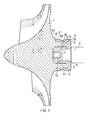
Figure 1 is a sectional elevation through a turbocharger impeller joined to a shaft by a connector in accordance with an embodiment of the invention; -
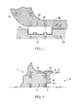
Figure 2 is a close-up schematic view of a seal between a section of a casing of the impeller ofFigure 1 and a sleeve portion of the connector; -
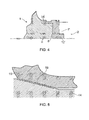
Figure 3 shows schematically a sectional elevation of a further embodiment of the connector; -
Figure 4 shows schematically a sectional elevation of a further embodiment of the connector; -
Figure 5 is a close-up schematic view of a seal between a section of a casing of an impeller and a sleeve portion of a further embodiment of the connector; -
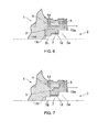
Figure 6 shows schematically a sectional elevation of a further embodiment of the connector; and -
Figure 7 shows schematically a sectional elevation of a further embodiment of the connector. - Referring first to
Figure 1 , an aluminium alloy impeller 1 is fitted on to asteel turbocharger shaft 2 by means of a steel connector. The alloy of which the impeller is made (known in the U.S.A. by the designation "2618A") has a relatively high strength for use up to a temperature of about 200°C, having a composition of aluminium with about 2.5wt.% copper and smaller amounts of magnesium, iron and nickel. The connector may be made of a high tensile steel such as EN26, whose composition includes about 2.5wt.% nickel, and is located at a hub extension H of the body of impeller 1. - The
shaft 2 is formed at its end with afirst shoulder 4 surrounding acylindrical centring portion 5, and a screw-threadedportion 7 of further reduced diameter extending from the end of the centring portion. The steel connector has an insertion part 3 of cup-like shape which is inserted into a central recess formed in the hub extension H, and acylindrical sleeve portion 14 around the hub extension H.An abutment portion 21 at the impeller side end of thesleeve portion 14 engages against an impeller-side end face 22 of the hub extension H to determine the relative axial positions of thesleeve portion 14 and the hub extension H. Alip portion 8 around the mouth of the insertion part 3 joins thesleeve portion 14 and the insertion part 3. Thelip portion 8 has a small clearance from the shaft-side end face 9 of the hub extension H, but is engaged on its other side by theshoulder 4 on theshaft 2. Thecentring portion 5 of the shaft is received in acorresponding centring portion 10 of the insertion part 3 in a close, but not tight, fit. The end of the insertion part 3 forms a threadedportion 12 having a threadedbore 11 which engages on the screw-threadedportion 7 of the shaft. The threadedportion 12 has a small clearance from the end of the recess. - The
sleeve portion 14 is fitted on to the hub extension by heating the connector to causesleeve portion 14 to expand, and then slippingsleeve portion 14 on to the cylindrical outer surface of the hub extension H where, on cooling, it frictionally grips. Thesleeve portion 14 extends over and thereby frictionally contacts most of the axial length of the hub extension H, although in other embodiments thesleeve portion 14 can be extend over only a portion of the axial length, and/or frictional contact can extend between thesleeve portion 14 and the hub extension H over only a portion of the overlap region between thesleeve portion 14 and the hub extension H. It should be noted that the steel of the connector has a lower coefficient of thermal expansion than the aluminium alloy of the impeller and hence thesleeve portion 14 does not expand as much with rising temperature as the hub extension H. This difference in their respective coefficients of expansion ensures that during operation, as the impeller assembly heats up, the joint between the hub extension and the sleeve tightens, reducing any tendency for relative movement between impeller and connector under the influence of centrifugal and thermal stresses, and increasing the torque capacity of the joint. - At its shaft-side end, the outer diameter of the
sleeve portion 14 is provided with an oil capture/thrower ring R, which in this embodiment of the invention is machined into thesleeve portion 14. Another option, however, is to form the ring R as a separate component. - As shown better in
Figure 2 , asection 15 of the impeller casing and the outer surface of thesleeve portion 14 are in close proximity to help provide a rotating oil and pressure seal between the impeller 1 and the casing. To improve the seal, thesleeve portion 14 has arecess 13 on its outer surface which receives a sealingring 16 carried by thecasing section 15. To reduce wear between the sealingring 16 and thesleeve portion 14, thecasing section 15 has asmall abutment surface 20 on the shaft side (right hand inFigure 1 ) of theseal ring 16 and against which the sealingring 16 rests. To provide enhanced sealing, the sealingring 16 hasannular grooves 18 on its radially inner face, and the recess has correspondingcircumferential ribs 17 which are received in the grooves, as described inEP A 1130220 . Alternatively, however, the sealing ring can be a plain ring (i.e. without grooves) received in a plain recess (i.e. without ribs). The sealingring 16 co-operates with thecasing section 15 and serves to retain lubricating oil to the shaft side of the assembly and compressed air to the impeller side of the assembly (left hand inFigure 1 ). The compressed air is contained between the body of the impeller 1, thesleeve portion 14 with itssealing ring 16, and the impeller casing, within which the impeller assembly is mounted for rotation on overhung bearings (not shown). - The impeller assembly is built up as follows. The connector is warmed, and the
sleeve portion 14 is slid on to the cylindrical outer surface of the hub extension H until theabutment portion 21 contacts theend face 22 of the hub extension H. The insertion part 3 of the connector inserts into the central recess of the hub extension H. When the connector cools, a frictional connection is thus formed between thesleeve portion 14 and the hub extension H. However, the connector is sized such that a clearance C prevents the insertion part 3 from contacting the side of the central recess. The screw-threadedportion 7 of theshaft 2 is then screwed onto the threadedportion 12 of the connector, therespective centring portions lip portion 8 andshoulder 4 come into abutment, which causes the threads to tighten and provides a rotationally fixed connection between the impeller 1 and theshaft 2. - Advantageously, the connector is a unitary body, which requires only one interference fit with the impeller 1. This reduces the number of high tolerance forming operations, and simplifies the joining procedure of the connector to the impeller 1. Further, because, in operation, the degree of interference increases when the temperature of the joint rises, the degree of interference required on build up can be reduced while maintaining the "walk" resistance and torque capacity of the joint. In addition, by containing the threaded connection between the connector and the
shaft 2 in the central recess of the hub extension H, an axially compact arrangement is achieved. The frictional connection between thesleeve portion 14 and the radially outer surface of the hub extension H transmits, in use, substantially all of the torque between theshaft 2 and the impeller 1. - If there is any tendency for the impeller 1 to "walk", advantageously this can be monitored by measuring the size of the gap that would open up between the
abutment portion 21 and theend face 22. For this reason, it is preferred that theabutment portion 21 and theend face 22 determine the relative axial positions of thesleeve portion 14 and the hub extension H. Alternative pairs of facing features that could be configured to abut each and thereby determine the relative axial positions (such as thelip portion 8 and the end face 9, or the threadedportion 12 and the end of the recess) are less amenable to inspection. -
Figure 3 shows schematically a sectional elevation of a further embodiment of the connector. In this embodiment there is no central recess in the hub extension H of the impeller 1. Consequently, there is also no insertion part of the connector. Instead, the threadedportion 12 of the connector is at the radially inner end of thelip portion 8. The centringportion 10 of the connector is in turn formed on the radially inner side and at the shaft-side end of thesleeve portion 14. This makes the tightly toleranced interference surface of thesleeve portion 14 easier to manufacture, but results in an axially longer arrangement. -
Figure 4 shows schematically a sectional elevation of a further embodiment of the connector, In this embodiment the threaded portion 12' of the connector is formed as a cylindrical boss which fits into a cylindrical recess formed in theshaft 2. The threaded portion 12' carries its thread on a radially outer surface of the boss, while the corresponding threaded portion 7' of theshaft 2 is formed around the cylindrical recess and is threaded on a surface which faces radially inwards. -
Figure 5 is a close-up schematic view of a seal between a section of a casing of an impeller and a sleeve portion of a further embodiment of the connector. In this case, instead of a seal formed by a sealing ring, thesleeve portion 14 and thecasing section 15 have engaging surfaces 19 carrying respective sets of machined grooves which interlock to form a labyrinth seal. -
Figure 6 shows schematically a sectional elevation of a further embodiment of the connector. This embodiment is similar to the first embodiment except that theshaft 2 has twocentring portions corresponding centring portions portions shaft 2 and the connector are located axially between the engaging pairs of centring portions such that, on each of the shaft and the connector, the respective diameters of the threaded portions and the centring portions decrease towards the impeller. A further difference relative to the first embodiment is that the threads are tapered, so that merely screwing the threadedportions shaft 2. -
Figure 7 shows schematically a sectional elevation of a further embodiment of the connector. This embodiment is similar to the embodiment ofFigure 6 except that the impeller-side centring portion 10b' which engages withshaft centring portion 5b is formed by the impeller rather than by the connector. - While the invention has been described in conjunction with the exemplary embodiments described above, many equivalent modifications and variations will be apparent to those skilled in the art when given this disclosure. Accordingly, the exemplary embodiments of the invention set forth above are considered to be illustrative and not limiting.
Claims (15)
- A connector for connecting an impeller (1) to a shaft (2), the connector having:a sleeve portion (14) which is frictionally connected on a radially outer surface of a shaft-side hub extension (H) of the impeller, anda threaded portion (12) carrying a thread which screws onto a corresponding threaded portion (7) of the shaft, such that the connector provides a rotationally fixed connection between the impeller and the shaft; andwherein:the hub extension has a central recess, and a part (3) of the connector is inserted into the recess;characterised in that:the connector is formed as a unitary body; andthe frictional connection between the sleeve portion and the radially outer surface of the hub extension transmits, in use, substantially all of the torque between the shaft and the impeller.
- A connector according to claim 1, wherein the connector is configured to contact the impeller only on the radially outer surface of the hub extension.
- A connector according to claim 1, wherein the hub extension has an end face (22), and the connector has an abutment portion (21) which bears against the end face.
- A connector according to claim 3, wherein the connector is configured to contact the impeller only on the radially outer surface of the hub extension and the end face of the hub extension.
- A connector according to any one of the previous claims, wherein the part of the connector inserted into the recess includes the threaded portion of the connector.
- A connector according to any one of the previous claims, wherein the connector is formed of a material having a greater strength than the material of the impeller and having a lower coefficient of thermal expansion than the material of the impeller.
- A connector according to any one of the previous claims, wherein the sleeve portion extends over at least 50% of the axial length of the hub extension.
- A connector according to any one of the previous claims, wherein the connector and/or the impeller has one or more centring portions (10; 10a, 10b; 10a, 10b') having respective engagement surfaces which engage with one or more corresponding centring portions (5; 5a, 5b) of the shaft, the threaded portion of the connector and the centring portions of the connector and/or the impeller being distributed along the impeller axis.
- A connector according to any one of the previous claims, wherein the impeller has a casing and the sleeve portion forms a seal with a section (15) of the casing.
- A connector according to any one of the previous claims, wherein the sleeve portion is formed with or carries a circumferential oil thrower formation (R) at its radially outer surface.
- A connector according to any one of the previous claims, wherein a clearance is provided between the part of the connector inserted into the recess and the side surface of the recess.
- An impeller having a shaft-side hub extension and fitted with a connector according to any one of the previous claims, the sleeve portion of the connector being frictionally connected on a radially outer surface of the hub extension.
- The impeller fitted with a connector of claim 12, wherein the impeller is a metal impeller.
- The impeller fitted with a connector of claim 12 or 13, which impeller is connected to a shaft having a corresponding threaded portion, the thread of the threaded portion of the connector screwing onto the corresponding threaded portion of the shaft.
- A turbocharger having the connected impeller and shaft of claim 14.
Applications Claiming Priority (2)
| Application Number | Priority Date | Filing Date | Title |
|---|---|---|---|
| GB201122236A GB201122236D0 (en) | 2011-12-23 | 2011-12-23 | Connector |
| PCT/GB2012/053097 WO2013093424A1 (en) | 2011-12-23 | 2012-12-12 | Connector |
Publications (2)
| Publication Number | Publication Date |
|---|---|
| EP2795065A1 EP2795065A1 (en) | 2014-10-29 |
| EP2795065B1 true EP2795065B1 (en) | 2015-08-19 |
Family
ID=45572976
Family Applications (1)
| Application Number | Title | Priority Date | Filing Date |
|---|---|---|---|
| EP12809313.5A Active EP2795065B1 (en) | 2011-12-23 | 2012-12-12 | Connector |
Country Status (8)
| Country | Link |
|---|---|
| US (1) | US9074477B2 (en) |
| EP (1) | EP2795065B1 (en) |
| JP (1) | JP5731081B2 (en) |
| KR (1) | KR101491431B1 (en) |
| CN (2) | CN103174467B (en) |
| GB (1) | GB201122236D0 (en) |
| IN (1) | IN2014KN01480A (en) |
| WO (1) | WO2013093424A1 (en) |
Families Citing this family (11)
| Publication number | Priority date | Publication date | Assignee | Title |
|---|---|---|---|---|
| GB201200403D0 (en) * | 2012-01-10 | 2012-02-22 | Napier Turbochargers Ltd | Connector |
| GB201221429D0 (en) * | 2012-11-28 | 2013-01-09 | Napier Turbochargers Ltd | Impeller shaft |
| CN203306224U (en) | 2013-05-31 | 2013-11-27 | 深圳市大疆创新科技有限公司 | Propeller and aircraft provided with same |
| DE102013015563A1 (en) * | 2013-09-20 | 2015-03-26 | Abb Turbo Systems Ag | turbocharger |
| CN105829731B (en) * | 2014-02-26 | 2018-01-05 | 三菱重工业株式会社 | The manufacture method of centrifugal compressor, the turbocharger with the centrifugal compressor and the centrifugal compressor |
| JP6846504B2 (en) | 2017-03-15 | 2021-03-24 | 三菱重工エンジン&ターボチャージャ株式会社 | Supercharger |
| CN107023506B (en) * | 2017-05-10 | 2019-08-23 | 巢湖市聚源机械有限公司 | A kind of water pump being convenient for changing blade |
| US11021975B2 (en) * | 2019-02-12 | 2021-06-01 | Pratt & Whitney Canada Corp | Gas turbine engine and rotary assembly therefor |
| JP7375694B2 (en) * | 2020-07-15 | 2023-11-08 | 株式会社豊田自動織機 | centrifugal compressor |
| US11365630B1 (en) * | 2020-12-28 | 2022-06-21 | Rolls-Royce North American Technologies Inc. | Fan rotor with tapered drive joint |
| US11739763B2 (en) * | 2021-11-11 | 2023-08-29 | Progress Rail Locomotive Inc. | Impeller attach mechanism |
Family Cites Families (16)
| Publication number | Priority date | Publication date | Assignee | Title |
|---|---|---|---|---|
| US2433589A (en) * | 1939-05-25 | 1947-12-30 | Nash Engineering Co | Pump |
| DE2728823C2 (en) | 1977-06-27 | 1982-09-09 | Aktiengesellschaft Kühnle, Kopp & Kausch, 6710 Frankenthal | Gas turbine |
| JPS60103082A (en) | 1983-11-09 | 1985-06-07 | 日本碍子株式会社 | Metal ceramic bonded body and manufacture |
| US4832573A (en) | 1987-11-27 | 1989-05-23 | General Motors Corporation | Integral connection for plastic water pump impeller |
| US5176497A (en) * | 1991-01-22 | 1993-01-05 | Allied-Signal Inc. | Boreless hub compressor wheel assembly for a turbocharger |
| US5505590A (en) | 1994-04-26 | 1996-04-09 | Freudenberg-Nok General Partnership | Composite torque converter components |
| GB2359863B (en) | 2000-03-04 | 2003-03-26 | Alstom | Turbocharger |
| US6364634B1 (en) | 2000-09-29 | 2002-04-02 | General Motors Corporation | Turbocharger rotor with alignment couplings |
| DE50308692D1 (en) * | 2002-05-06 | 2008-01-10 | Abb Turbo Systems Ag | FASTENING DEVICE FOR A WHEEL ON A SHAFT |
| GB2392477A (en) | 2002-08-24 | 2004-03-03 | Alstom | Turbocharger |
| US6896479B2 (en) * | 2003-04-08 | 2005-05-24 | General Motors Corporation | Turbocharger rotor |
| EP1803941A1 (en) | 2004-10-19 | 2007-07-04 | Komatsu Ltd | Turbo machine, compressor impeller used for turbo machine, and method of manufacturing turbo machine |
| US7748960B1 (en) * | 2006-05-04 | 2010-07-06 | Florida Turbine Technologies, Inc. | Hub to shaft connection |
| DE102007012641A1 (en) * | 2007-03-16 | 2008-09-18 | Daimler Ag | Tool for an exhaust gas turbocharger |
| DE102008056058A1 (en) * | 2008-08-04 | 2010-02-11 | Mtu Friedrichshafen Gmbh | Exhaust gas turbo charger, has rotor and compressor rotor coaxially connected via shaft, thread adapter screwed on shaft from side of compressor, and centric recess provided with internal thread fitted at external thread at thread adapter |
| DE102008038007A1 (en) * | 2008-08-16 | 2010-02-18 | Bosch Mahle Turbo Systems Gmbh & Co. Kg | turbocharger |
-
2011
- 2011-12-23 GB GB201122236A patent/GB201122236D0/en not_active Ceased
-
2012
- 2012-12-12 IN IN1480KON2014 patent/IN2014KN01480A/en unknown
- 2012-12-12 EP EP12809313.5A patent/EP2795065B1/en active Active
- 2012-12-12 JP JP2014548177A patent/JP5731081B2/en active Active
- 2012-12-12 US US14/364,874 patent/US9074477B2/en active Active
- 2012-12-12 WO PCT/GB2012/053097 patent/WO2013093424A1/en active Application Filing
- 2012-12-12 KR KR20147017761A patent/KR101491431B1/en active IP Right Grant
- 2012-12-24 CN CN201210568197.XA patent/CN103174467B/en active Active
- 2012-12-24 CN CN2012207207042U patent/CN203296826U/en not_active Expired - Fee Related
Also Published As
| Publication number | Publication date |
|---|---|
| WO2013093424A1 (en) | 2013-06-27 |
| GB201122236D0 (en) | 2012-02-01 |
| JP2015502492A (en) | 2015-01-22 |
| US20140369840A1 (en) | 2014-12-18 |
| US9074477B2 (en) | 2015-07-07 |
| CN203296826U (en) | 2013-11-20 |
| KR101491431B1 (en) | 2015-02-06 |
| IN2014KN01480A (en) | 2015-10-23 |
| CN103174467B (en) | 2016-04-20 |
| CN103174467A (en) | 2013-06-26 |
| EP2795065A1 (en) | 2014-10-29 |
| JP5731081B2 (en) | 2015-06-10 |
| KR20140091617A (en) | 2014-07-21 |
Similar Documents
| Publication | Publication Date | Title |
|---|---|---|
| EP2795065B1 (en) | Connector | |
| EP2933499B1 (en) | Turbocharger impeller screwed onto shaft with arrangement for accommodating thermal dilatation | |
| EP1394387B2 (en) | Turbochargers | |
| US20150044047A1 (en) | Turbocharger having a connector for connecting an impeller to a shaft | |
| JP4339782B2 (en) | Fixing device for fixing the impeller to the shaft | |
| WO2013110922A1 (en) | Connection system, corresponding impeller and turbocharger | |
| US10309300B2 (en) | Electric rotor fit onto a turbomachine shaft | |
| GB2498361A (en) | Silicon carbide reinforced aluminium alloy turbocharger impeller | |
| GB2500167A (en) | Impeller to shaft connector | |
| GB2498377A (en) | Impeller to shaft connection | |
| GB2498748A (en) | Impeller to shaft connection system |
Legal Events
| Date | Code | Title | Description |
|---|---|---|---|
| PUAI | Public reference made under article 153(3) epc to a published international application that has entered the european phase |
Free format text: ORIGINAL CODE: 0009012 |
|
| 17P | Request for examination filed |
Effective date: 20140618 |
|
| AK | Designated contracting states |
Kind code of ref document: A1 Designated state(s): AL AT BE BG CH CY CZ DE DK EE ES FI FR GB GR HR HU IE IS IT LI LT LU LV MC MK MT NL NO PL PT RO RS SE SI SK SM TR |
|
| REG | Reference to a national code |
Ref country code: DE Ref legal event code: R079 Ref document number: 602012009895 Country of ref document: DE Free format text: PREVIOUS MAIN CLASS: F01D0005020000 Ipc: F16D0001076000 |
|
| RIC1 | Information provided on ipc code assigned before grant |
Ipc: F16D 1/076 20060101AFI20150113BHEP |
|
| GRAP | Despatch of communication of intention to grant a patent |
Free format text: ORIGINAL CODE: EPIDOSNIGR1 |
|
| DAX | Request for extension of the european patent (deleted) | ||
| INTG | Intention to grant announced |
Effective date: 20150323 |
|
| GRAP | Despatch of communication of intention to grant a patent |
Free format text: ORIGINAL CODE: EPIDOSNIGR1 |
|
| INTG | Intention to grant announced |
Effective date: 20150520 |
|
| GRAS | Grant fee paid |
Free format text: ORIGINAL CODE: EPIDOSNIGR3 |
|
| GRAA | (expected) grant |
Free format text: ORIGINAL CODE: 0009210 |
|
| AK | Designated contracting states |
Kind code of ref document: B1 Designated state(s): AL AT BE BG CH CY CZ DE DK EE ES FI FR GB GR HR HU IE IS IT LI LT LU LV MC MK MT NL NO PL PT RO RS SE SI SK SM TR |
|
| REG | Reference to a national code |
Ref country code: GB Ref legal event code: FG4D |
|
| REG | Reference to a national code |
Ref country code: CH Ref legal event code: EP |
|
| REG | Reference to a national code |
Ref country code: IE Ref legal event code: FG4D |
|
| REG | Reference to a national code |
Ref country code: AT Ref legal event code: REF Ref document number: 744043 Country of ref document: AT Kind code of ref document: T Effective date: 20150915 |
|
| REG | Reference to a national code |
Ref country code: DE Ref legal event code: R096 Ref document number: 602012009895 Country of ref document: DE |
|
| REG | Reference to a national code |
Ref country code: FR Ref legal event code: PLFP Year of fee payment: 4 |
|
| REG | Reference to a national code |
Ref country code: AT Ref legal event code: MK05 Ref document number: 744043 Country of ref document: AT Kind code of ref document: T Effective date: 20150819 |
|
| REG | Reference to a national code |
Ref country code: LT Ref legal event code: MG4D |
|
| REG | Reference to a national code |
Ref country code: NL Ref legal event code: MP Effective date: 20150819 |
|
| PG25 | Lapsed in a contracting state [announced via postgrant information from national office to epo] |
Ref country code: NO Free format text: LAPSE BECAUSE OF FAILURE TO SUBMIT A TRANSLATION OF THE DESCRIPTION OR TO PAY THE FEE WITHIN THE PRESCRIBED TIME-LIMIT Effective date: 20151119 Ref country code: LV Free format text: LAPSE BECAUSE OF FAILURE TO SUBMIT A TRANSLATION OF THE DESCRIPTION OR TO PAY THE FEE WITHIN THE PRESCRIBED TIME-LIMIT Effective date: 20150819 Ref country code: GR Free format text: LAPSE BECAUSE OF FAILURE TO SUBMIT A TRANSLATION OF THE DESCRIPTION OR TO PAY THE FEE WITHIN THE PRESCRIBED TIME-LIMIT Effective date: 20151120 Ref country code: LT Free format text: LAPSE BECAUSE OF FAILURE TO SUBMIT A TRANSLATION OF THE DESCRIPTION OR TO PAY THE FEE WITHIN THE PRESCRIBED TIME-LIMIT Effective date: 20150819 |
|
| PG25 | Lapsed in a contracting state [announced via postgrant information from national office to epo] |
Ref country code: IS Free format text: LAPSE BECAUSE OF FAILURE TO SUBMIT A TRANSLATION OF THE DESCRIPTION OR TO PAY THE FEE WITHIN THE PRESCRIBED TIME-LIMIT Effective date: 20151219 Ref country code: RS Free format text: LAPSE BECAUSE OF FAILURE TO SUBMIT A TRANSLATION OF THE DESCRIPTION OR TO PAY THE FEE WITHIN THE PRESCRIBED TIME-LIMIT Effective date: 20150819 Ref country code: PT Free format text: LAPSE BECAUSE OF FAILURE TO SUBMIT A TRANSLATION OF THE DESCRIPTION OR TO PAY THE FEE WITHIN THE PRESCRIBED TIME-LIMIT Effective date: 20151221 Ref country code: SE Free format text: LAPSE BECAUSE OF FAILURE TO SUBMIT A TRANSLATION OF THE DESCRIPTION OR TO PAY THE FEE WITHIN THE PRESCRIBED TIME-LIMIT Effective date: 20150819 Ref country code: AT Free format text: LAPSE BECAUSE OF FAILURE TO SUBMIT A TRANSLATION OF THE DESCRIPTION OR TO PAY THE FEE WITHIN THE PRESCRIBED TIME-LIMIT Effective date: 20150819 Ref country code: ES Free format text: LAPSE BECAUSE OF FAILURE TO SUBMIT A TRANSLATION OF THE DESCRIPTION OR TO PAY THE FEE WITHIN THE PRESCRIBED TIME-LIMIT Effective date: 20150819 Ref country code: PL Free format text: LAPSE BECAUSE OF FAILURE TO SUBMIT A TRANSLATION OF THE DESCRIPTION OR TO PAY THE FEE WITHIN THE PRESCRIBED TIME-LIMIT Effective date: 20150819 |
|
| PG25 | Lapsed in a contracting state [announced via postgrant information from national office to epo] |
Ref country code: NL Free format text: LAPSE BECAUSE OF FAILURE TO SUBMIT A TRANSLATION OF THE DESCRIPTION OR TO PAY THE FEE WITHIN THE PRESCRIBED TIME-LIMIT Effective date: 20150819 |
|
| PG25 | Lapsed in a contracting state [announced via postgrant information from national office to epo] |
Ref country code: EE Free format text: LAPSE BECAUSE OF FAILURE TO SUBMIT A TRANSLATION OF THE DESCRIPTION OR TO PAY THE FEE WITHIN THE PRESCRIBED TIME-LIMIT Effective date: 20150819 Ref country code: DK Free format text: LAPSE BECAUSE OF FAILURE TO SUBMIT A TRANSLATION OF THE DESCRIPTION OR TO PAY THE FEE WITHIN THE PRESCRIBED TIME-LIMIT Effective date: 20150819 Ref country code: SK Free format text: LAPSE BECAUSE OF FAILURE TO SUBMIT A TRANSLATION OF THE DESCRIPTION OR TO PAY THE FEE WITHIN THE PRESCRIBED TIME-LIMIT Effective date: 20150819 |
|
| REG | Reference to a national code |
Ref country code: DE Ref legal event code: R097 Ref document number: 602012009895 Country of ref document: DE |
|
| PG25 | Lapsed in a contracting state [announced via postgrant information from national office to epo] |
Ref country code: RO Free format text: LAPSE BECAUSE OF FAILURE TO SUBMIT A TRANSLATION OF THE DESCRIPTION OR TO PAY THE FEE WITHIN THE PRESCRIBED TIME-LIMIT Effective date: 20150819 Ref country code: BE Free format text: LAPSE BECAUSE OF NON-PAYMENT OF DUE FEES Effective date: 20151231 |
|
| PLBE | No opposition filed within time limit |
Free format text: ORIGINAL CODE: 0009261 |
|
| STAA | Information on the status of an ep patent application or granted ep patent |
Free format text: STATUS: NO OPPOSITION FILED WITHIN TIME LIMIT |
|
| 26N | No opposition filed |
Effective date: 20160520 |
|
| PG25 | Lapsed in a contracting state [announced via postgrant information from national office to epo] |
Ref country code: MC Free format text: LAPSE BECAUSE OF FAILURE TO SUBMIT A TRANSLATION OF THE DESCRIPTION OR TO PAY THE FEE WITHIN THE PRESCRIBED TIME-LIMIT Effective date: 20150819 Ref country code: LU Free format text: LAPSE BECAUSE OF FAILURE TO SUBMIT A TRANSLATION OF THE DESCRIPTION OR TO PAY THE FEE WITHIN THE PRESCRIBED TIME-LIMIT Effective date: 20151212 |
|
| PG25 | Lapsed in a contracting state [announced via postgrant information from national office to epo] |
Ref country code: SI Free format text: LAPSE BECAUSE OF FAILURE TO SUBMIT A TRANSLATION OF THE DESCRIPTION OR TO PAY THE FEE WITHIN THE PRESCRIBED TIME-LIMIT Effective date: 20150819 |
|
| REG | Reference to a national code |
Ref country code: IE Ref legal event code: MM4A |
|
| PG25 | Lapsed in a contracting state [announced via postgrant information from national office to epo] |
Ref country code: IE Free format text: LAPSE BECAUSE OF NON-PAYMENT OF DUE FEES Effective date: 20151212 |
|
| REG | Reference to a national code |
Ref country code: FR Ref legal event code: PLFP Year of fee payment: 5 |
|
| PG25 | Lapsed in a contracting state [announced via postgrant information from national office to epo] |
Ref country code: BE Free format text: LAPSE BECAUSE OF FAILURE TO SUBMIT A TRANSLATION OF THE DESCRIPTION OR TO PAY THE FEE WITHIN THE PRESCRIBED TIME-LIMIT Effective date: 20150819 |
|
| PG25 | Lapsed in a contracting state [announced via postgrant information from national office to epo] |
Ref country code: SM Free format text: LAPSE BECAUSE OF FAILURE TO SUBMIT A TRANSLATION OF THE DESCRIPTION OR TO PAY THE FEE WITHIN THE PRESCRIBED TIME-LIMIT Effective date: 20150819 Ref country code: BG Free format text: LAPSE BECAUSE OF FAILURE TO SUBMIT A TRANSLATION OF THE DESCRIPTION OR TO PAY THE FEE WITHIN THE PRESCRIBED TIME-LIMIT Effective date: 20150819 |
|
| PG25 | Lapsed in a contracting state [announced via postgrant information from national office to epo] |
Ref country code: CY Free format text: LAPSE BECAUSE OF FAILURE TO SUBMIT A TRANSLATION OF THE DESCRIPTION OR TO PAY THE FEE WITHIN THE PRESCRIBED TIME-LIMIT Effective date: 20150819 Ref country code: HU Free format text: LAPSE BECAUSE OF FAILURE TO SUBMIT A TRANSLATION OF THE DESCRIPTION OR TO PAY THE FEE WITHIN THE PRESCRIBED TIME-LIMIT; INVALID AB INITIO Effective date: 20121212 |
|
| PG25 | Lapsed in a contracting state [announced via postgrant information from national office to epo] |
Ref country code: HR Free format text: LAPSE BECAUSE OF FAILURE TO SUBMIT A TRANSLATION OF THE DESCRIPTION OR TO PAY THE FEE WITHIN THE PRESCRIBED TIME-LIMIT Effective date: 20150819 |
|
| PG25 | Lapsed in a contracting state [announced via postgrant information from national office to epo] |
Ref country code: MT Free format text: LAPSE BECAUSE OF FAILURE TO SUBMIT A TRANSLATION OF THE DESCRIPTION OR TO PAY THE FEE WITHIN THE PRESCRIBED TIME-LIMIT Effective date: 20150819 |
|
| REG | Reference to a national code |
Ref country code: FR Ref legal event code: PLFP Year of fee payment: 6 |
|
| PG25 | Lapsed in a contracting state [announced via postgrant information from national office to epo] |
Ref country code: MK Free format text: LAPSE BECAUSE OF FAILURE TO SUBMIT A TRANSLATION OF THE DESCRIPTION OR TO PAY THE FEE WITHIN THE PRESCRIBED TIME-LIMIT Effective date: 20150819 |
|
| PG25 | Lapsed in a contracting state [announced via postgrant information from national office to epo] |
Ref country code: TR Free format text: LAPSE BECAUSE OF FAILURE TO SUBMIT A TRANSLATION OF THE DESCRIPTION OR TO PAY THE FEE WITHIN THE PRESCRIBED TIME-LIMIT Effective date: 20150819 Ref country code: AL Free format text: LAPSE BECAUSE OF FAILURE TO SUBMIT A TRANSLATION OF THE DESCRIPTION OR TO PAY THE FEE WITHIN THE PRESCRIBED TIME-LIMIT Effective date: 20150819 |
|
| REG | Reference to a national code |
Ref country code: GB Ref legal event code: 732E Free format text: REGISTERED BETWEEN 20220526 AND 20220601 |
|
| REG | Reference to a national code |
Ref country code: DE Ref legal event code: R082 Ref document number: 602012009895 Country of ref document: DE Representative=s name: LORENZ SEIDLER GOSSEL RECHTSANWAELTE PATENTANW, DE Ref country code: DE Ref legal event code: R082 Ref document number: 602012009895 Country of ref document: DE |
|
| REG | Reference to a national code |
Ref country code: FI Ref legal event code: PCE Owner name: WABTEC UK LIMITED |
|
| REG | Reference to a national code |
Ref country code: DE Ref legal event code: R081 Ref document number: 602012009895 Country of ref document: DE Owner name: WABTEC UK LTD., DONCASTER, GB Free format text: FORMER OWNER: NAPIER TURBOCHARGERS LIMITED, LINCOLN, GB Ref country code: DE Ref legal event code: R082 Ref document number: 602012009895 Country of ref document: DE Representative=s name: LORENZ SEIDLER GOSSEL RECHTSANWAELTE PATENTANW, DE |
|
| PGFP | Annual fee paid to national office [announced via postgrant information from national office to epo] |
Ref country code: DE Payment date: 20221219 Year of fee payment: 11 |
|
| PGFP | Annual fee paid to national office [announced via postgrant information from national office to epo] |
Ref country code: CH Payment date: 20221219 Year of fee payment: 11 |
|
| PGFP | Annual fee paid to national office [announced via postgrant information from national office to epo] |
Ref country code: IT Payment date: 20221219 Year of fee payment: 11 |
|
| P01 | Opt-out of the competence of the unified patent court (upc) registered |
Effective date: 20230530 |
|
| PGFP | Annual fee paid to national office [announced via postgrant information from national office to epo] |
Ref country code: GB Payment date: 20231215 Year of fee payment: 12 |
|
| PGFP | Annual fee paid to national office [announced via postgrant information from national office to epo] |
Ref country code: FR Payment date: 20231227 Year of fee payment: 12 Ref country code: FI Payment date: 20231222 Year of fee payment: 12 Ref country code: CZ Payment date: 20231122 Year of fee payment: 12 |