EP2793466A1 - Procédé de codage d'image vidéo, dispositif de codage d'image vidéo, procédé de décodage d'image vidéo, dispositif de décodage d'image vidéo et dispositif de codage et de décodage d'image vidéo - Google Patents
Procédé de codage d'image vidéo, dispositif de codage d'image vidéo, procédé de décodage d'image vidéo, dispositif de décodage d'image vidéo et dispositif de codage et de décodage d'image vidéo Download PDFInfo
- Publication number
- EP2793466A1 EP2793466A1 EP12857032.2A EP12857032A EP2793466A1 EP 2793466 A1 EP2793466 A1 EP 2793466A1 EP 12857032 A EP12857032 A EP 12857032A EP 2793466 A1 EP2793466 A1 EP 2793466A1
- Authority
- EP
- European Patent Office
- Prior art keywords
- motion vector
- block
- list
- magnitude
- decoding
- Prior art date
- Legal status (The legal status is an assumption and is not a legal conclusion. Google has not performed a legal analysis and makes no representation as to the accuracy of the status listed.)
- Ceased
Links
Images


Classifications
-
- H—ELECTRICITY
- H04—ELECTRIC COMMUNICATION TECHNIQUE
- H04N—PICTORIAL COMMUNICATION, e.g. TELEVISION
- H04N19/00—Methods or arrangements for coding, decoding, compressing or decompressing digital video signals
- H04N19/10—Methods or arrangements for coding, decoding, compressing or decompressing digital video signals using adaptive coding
- H04N19/102—Methods or arrangements for coding, decoding, compressing or decompressing digital video signals using adaptive coding characterised by the element, parameter or selection affected or controlled by the adaptive coding
- H04N19/103—Selection of coding mode or of prediction mode
- H04N19/105—Selection of the reference unit for prediction within a chosen coding or prediction mode, e.g. adaptive choice of position and number of pixels used for prediction
-
- H—ELECTRICITY
- H04—ELECTRIC COMMUNICATION TECHNIQUE
- H04N—PICTORIAL COMMUNICATION, e.g. TELEVISION
- H04N19/00—Methods or arrangements for coding, decoding, compressing or decompressing digital video signals
- H04N19/10—Methods or arrangements for coding, decoding, compressing or decompressing digital video signals using adaptive coding
- H04N19/134—Methods or arrangements for coding, decoding, compressing or decompressing digital video signals using adaptive coding characterised by the element, parameter or criterion affecting or controlling the adaptive coding
- H04N19/136—Incoming video signal characteristics or properties
- H04N19/137—Motion inside a coding unit, e.g. average field, frame or block difference
- H04N19/139—Analysis of motion vectors, e.g. their magnitude, direction, variance or reliability
-
- H—ELECTRICITY
- H04—ELECTRIC COMMUNICATION TECHNIQUE
- H04N—PICTORIAL COMMUNICATION, e.g. TELEVISION
- H04N19/00—Methods or arrangements for coding, decoding, compressing or decompressing digital video signals
- H04N19/10—Methods or arrangements for coding, decoding, compressing or decompressing digital video signals using adaptive coding
- H04N19/102—Methods or arrangements for coding, decoding, compressing or decompressing digital video signals using adaptive coding characterised by the element, parameter or selection affected or controlled by the adaptive coding
- H04N19/13—Adaptive entropy coding, e.g. adaptive variable length coding [AVLC] or context adaptive binary arithmetic coding [CABAC]
-
- H—ELECTRICITY
- H04—ELECTRIC COMMUNICATION TECHNIQUE
- H04N—PICTORIAL COMMUNICATION, e.g. TELEVISION
- H04N19/00—Methods or arrangements for coding, decoding, compressing or decompressing digital video signals
- H04N19/10—Methods or arrangements for coding, decoding, compressing or decompressing digital video signals using adaptive coding
- H04N19/134—Methods or arrangements for coding, decoding, compressing or decompressing digital video signals using adaptive coding characterised by the element, parameter or criterion affecting or controlling the adaptive coding
- H04N19/136—Incoming video signal characteristics or properties
- H04N19/137—Motion inside a coding unit, e.g. average field, frame or block difference
-
- H—ELECTRICITY
- H04—ELECTRIC COMMUNICATION TECHNIQUE
- H04N—PICTORIAL COMMUNICATION, e.g. TELEVISION
- H04N19/00—Methods or arrangements for coding, decoding, compressing or decompressing digital video signals
- H04N19/10—Methods or arrangements for coding, decoding, compressing or decompressing digital video signals using adaptive coding
- H04N19/134—Methods or arrangements for coding, decoding, compressing or decompressing digital video signals using adaptive coding characterised by the element, parameter or criterion affecting or controlling the adaptive coding
- H04N19/146—Data rate or code amount at the encoder output
- H04N19/15—Data rate or code amount at the encoder output by monitoring actual compressed data size at the memory before deciding storage at the transmission buffer
-
- H—ELECTRICITY
- H04—ELECTRIC COMMUNICATION TECHNIQUE
- H04N—PICTORIAL COMMUNICATION, e.g. TELEVISION
- H04N19/00—Methods or arrangements for coding, decoding, compressing or decompressing digital video signals
- H04N19/10—Methods or arrangements for coding, decoding, compressing or decompressing digital video signals using adaptive coding
- H04N19/134—Methods or arrangements for coding, decoding, compressing or decompressing digital video signals using adaptive coding characterised by the element, parameter or criterion affecting or controlling the adaptive coding
- H04N19/157—Assigned coding mode, i.e. the coding mode being predefined or preselected to be further used for selection of another element or parameter
- H04N19/159—Prediction type, e.g. intra-frame, inter-frame or bidirectional frame prediction
-
- H—ELECTRICITY
- H04—ELECTRIC COMMUNICATION TECHNIQUE
- H04N—PICTORIAL COMMUNICATION, e.g. TELEVISION
- H04N19/00—Methods or arrangements for coding, decoding, compressing or decompressing digital video signals
- H04N19/10—Methods or arrangements for coding, decoding, compressing or decompressing digital video signals using adaptive coding
- H04N19/169—Methods or arrangements for coding, decoding, compressing or decompressing digital video signals using adaptive coding characterised by the coding unit, i.e. the structural portion or semantic portion of the video signal being the object or the subject of the adaptive coding
- H04N19/17—Methods or arrangements for coding, decoding, compressing or decompressing digital video signals using adaptive coding characterised by the coding unit, i.e. the structural portion or semantic portion of the video signal being the object or the subject of the adaptive coding the unit being an image region, e.g. an object
- H04N19/176—Methods or arrangements for coding, decoding, compressing or decompressing digital video signals using adaptive coding characterised by the coding unit, i.e. the structural portion or semantic portion of the video signal being the object or the subject of the adaptive coding the unit being an image region, e.g. an object the region being a block, e.g. a macroblock
-
- H—ELECTRICITY
- H04—ELECTRIC COMMUNICATION TECHNIQUE
- H04N—PICTORIAL COMMUNICATION, e.g. TELEVISION
- H04N19/00—Methods or arrangements for coding, decoding, compressing or decompressing digital video signals
- H04N19/44—Decoders specially adapted therefor, e.g. video decoders which are asymmetric with respect to the encoder
-
- H—ELECTRICITY
- H04—ELECTRIC COMMUNICATION TECHNIQUE
- H04N—PICTORIAL COMMUNICATION, e.g. TELEVISION
- H04N19/00—Methods or arrangements for coding, decoding, compressing or decompressing digital video signals
- H04N19/50—Methods or arrangements for coding, decoding, compressing or decompressing digital video signals using predictive coding
- H04N19/503—Methods or arrangements for coding, decoding, compressing or decompressing digital video signals using predictive coding involving temporal prediction
- H04N19/51—Motion estimation or motion compensation
- H04N19/513—Processing of motion vectors
- H04N19/517—Processing of motion vectors by encoding
- H04N19/52—Processing of motion vectors by encoding by predictive encoding
-
- H—ELECTRICITY
- H04—ELECTRIC COMMUNICATION TECHNIQUE
- H04N—PICTORIAL COMMUNICATION, e.g. TELEVISION
- H04N19/00—Methods or arrangements for coding, decoding, compressing or decompressing digital video signals
- H04N19/50—Methods or arrangements for coding, decoding, compressing or decompressing digital video signals using predictive coding
- H04N19/503—Methods or arrangements for coding, decoding, compressing or decompressing digital video signals using predictive coding involving temporal prediction
- H04N19/51—Motion estimation or motion compensation
- H04N19/56—Motion estimation with initialisation of the vector search, e.g. estimating a good candidate to initiate a search
-
- H—ELECTRICITY
- H04—ELECTRIC COMMUNICATION TECHNIQUE
- H04N—PICTORIAL COMMUNICATION, e.g. TELEVISION
- H04N19/00—Methods or arrangements for coding, decoding, compressing or decompressing digital video signals
- H04N19/50—Methods or arrangements for coding, decoding, compressing or decompressing digital video signals using predictive coding
- H04N19/503—Methods or arrangements for coding, decoding, compressing or decompressing digital video signals using predictive coding involving temporal prediction
- H04N19/51—Motion estimation or motion compensation
- H04N19/567—Motion estimation based on rate distortion criteria
-
- H—ELECTRICITY
- H04—ELECTRIC COMMUNICATION TECHNIQUE
- H04N—PICTORIAL COMMUNICATION, e.g. TELEVISION
- H04N19/00—Methods or arrangements for coding, decoding, compressing or decompressing digital video signals
- H04N19/50—Methods or arrangements for coding, decoding, compressing or decompressing digital video signals using predictive coding
- H04N19/593—Methods or arrangements for coding, decoding, compressing or decompressing digital video signals using predictive coding involving spatial prediction techniques
-
- H—ELECTRICITY
- H04—ELECTRIC COMMUNICATION TECHNIQUE
- H04N—PICTORIAL COMMUNICATION, e.g. TELEVISION
- H04N19/00—Methods or arrangements for coding, decoding, compressing or decompressing digital video signals
- H04N19/60—Methods or arrangements for coding, decoding, compressing or decompressing digital video signals using transform coding
- H04N19/61—Methods or arrangements for coding, decoding, compressing or decompressing digital video signals using transform coding in combination with predictive coding
-
- H—ELECTRICITY
- H04—ELECTRIC COMMUNICATION TECHNIQUE
- H04N—PICTORIAL COMMUNICATION, e.g. TELEVISION
- H04N19/00—Methods or arrangements for coding, decoding, compressing or decompressing digital video signals
- H04N19/70—Methods or arrangements for coding, decoding, compressing or decompressing digital video signals characterised by syntax aspects related to video coding, e.g. related to compression standards
-
- H—ELECTRICITY
- H04—ELECTRIC COMMUNICATION TECHNIQUE
- H04N—PICTORIAL COMMUNICATION, e.g. TELEVISION
- H04N7/00—Television systems
-
- H—ELECTRICITY
- H04—ELECTRIC COMMUNICATION TECHNIQUE
- H04N—PICTORIAL COMMUNICATION, e.g. TELEVISION
- H04N19/00—Methods or arrangements for coding, decoding, compressing or decompressing digital video signals
- H04N19/10—Methods or arrangements for coding, decoding, compressing or decompressing digital video signals using adaptive coding
- H04N19/102—Methods or arrangements for coding, decoding, compressing or decompressing digital video signals using adaptive coding characterised by the element, parameter or selection affected or controlled by the adaptive coding
- H04N19/124—Quantisation
-
- H—ELECTRICITY
- H04—ELECTRIC COMMUNICATION TECHNIQUE
- H04N—PICTORIAL COMMUNICATION, e.g. TELEVISION
- H04N19/00—Methods or arrangements for coding, decoding, compressing or decompressing digital video signals
- H04N19/10—Methods or arrangements for coding, decoding, compressing or decompressing digital video signals using adaptive coding
- H04N19/169—Methods or arrangements for coding, decoding, compressing or decompressing digital video signals using adaptive coding characterised by the coding unit, i.e. the structural portion or semantic portion of the video signal being the object or the subject of the adaptive coding
- H04N19/17—Methods or arrangements for coding, decoding, compressing or decompressing digital video signals using adaptive coding characterised by the coding unit, i.e. the structural portion or semantic portion of the video signal being the object or the subject of the adaptive coding the unit being an image region, e.g. an object
- H04N19/172—Methods or arrangements for coding, decoding, compressing or decompressing digital video signals using adaptive coding characterised by the coding unit, i.e. the structural portion or semantic portion of the video signal being the object or the subject of the adaptive coding the unit being an image region, e.g. an object the region being a picture, frame or field
Definitions
- the present invention relates to a moving picture coding method for coding pictures on a block-by-block basis, and a moving picture decoding method for decoding pictures on a block-by-block basis.
- picture data of a current block is decoded by predicting a bi-predictive reference block included in a B slice using, as references, two items of picture data which is data of pictures different from the picture including the current block.
- prediction in the temporal direct mode involves multiplication for scaling.
- Such multiplication may cause increase in load in coding or decoding because motion vectors used in coding or decoding may need to be handled at a higher bit precision.
- one non-limiting and exemplary embodiment provides a moving picture coding method and a moving picture decoding method each of which may cause reduced load and be performed with the same coding efficiency.
- a moving picture coding method is a moving picture coding method for coding pictures on a block-by-block basis, and includes: selectively adding, to a list, a motion vector of each of one or more corresponding blocks each of which is (i) a block included in a current picture to be coded and spatially neighboring a current block to be coded or (ii) a block included in a picture other than the current picture and temporally neighboring the current block; selecting a motion vector from among the motion vectors in the list, the selected motion vector being to be used for coding the current block; and coding the current block using the motion vector selected in the selecting, wherein in the adding, a scaling process is performed on a first motion vector of the temporally neighboring corresponding block to calculate a second motion vector, whether the calculated second motion vector has a magnitude that is within a predetermined magnitude range or a magnitude that is not within the predetermined magnitude is determined, and the second motion vector is added to the list as the motion vector of the corresponding
- a moving picture decoding method is a moving picture decoding method for decoding pictures on a block-by-block basis, and includes: selectively adding, to a list, a motion vector of each of one or more corresponding blocks each of which is (i) a block included in a current picture to be decoded and spatially neighboring a current block to be decoded or (ii) a block included in a picture other than the current picture and temporally neighboring the current block; selecting a motion vector from among the motion vectors in the list, the selected motion vector being to be used for decoding the current block; and decoding the current block using the motion vector selected in the selecting, wherein in the adding, a scaling process is performed on a first motion vector of the temporally neighboring corresponding block to calculate a second motion vector, whether the calculated second motion vector has a magnitude that is within a predetermined magnitude range or a magnitude that is not within the predetermined magnitude is determined, and the second motion vector is added to the list as the motion
- the moving picture coding methods and the moving picture decoding methods according to the present invention each enables coding or decoding of moving pictures with reduced processing load while causing no reduction in coding efficiency.
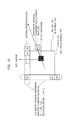
- FIG. 1 illustrates two pictures referenced for decoding of a current block (Curr_Blk).
- the numbers “300" to "304" are picture numbers (PicNum), and the pictures are arranged in ascending order of values of display order (PicOrderCnt).
- the current block to be decoded is included in a picture numbered 302 (CurrPic).
- the current block to be decoded references a picture having a PicNum of 301 and a picture having a PicNum of 304.
- the picture having a PicNum of 301 precedes the picture including the current block in the display order
- the picture having a PicNum of 304 follows the picture including the current block in the display order.
- the starting point of an arrow indicates a referencing picture (a picture to be decoded) and the head of an arrow indicates a picture to be used for decoding (a picture to be referenced) as described in the legend to FIG. 1 .
- FIG. 2A and FIG. 2B illustrate two reference picture lists, RefPicList0 and RefPicList1, respectively.
- FIG. 2A illustrates a reference picture list 0 (RefPicList0) which is a list for identifying one of two reference pictures.
- FIG. 2B shows a reference picture list 1 (RefPicList1) which is a list for identifying the other of the two reference pictures.
- Entries in the reference picture lists RefPicList0 and RefPicList1 are reordered so that indices having less values in the reference picture list RefPicList0 and the reference picture list RefPicList1 indicate pictures having different picture numbers picNum.
- Each of the reference picture lists are divided into the first half including pictures preceding the picNum302 and the second half including pictures following the picNum302.
- the picture indices are assigned picture numbers in descending order (301, 300).
- the picture indices are assigned picture numbers in ascending order (303, 304).
- One of the reference pictures is a picture indicated by RefPicList0[0], which is a picture 301 immediately before the picture 302.
- the other of the reference pictures is a picture indicated by RefPicList1[0], which is a picture 303 immediately after the picture 302.
- one index refIdxL0 is 0, and therefore the current picture 302 references the picture 301.
- the other index refIdxL1 is 1, and therefore the current picture 302 references the picture 304.
- FIG. 3 illustrates picNum in the case where the values of refIdxL0 and refIdxL1 in each of the reference picture lists RefPicList0 and RefPicList1 of the CurrBlk included in the picture 302 increase from "0". Greater values in the list (the value of refIdxL0 and the value of refIdxL1) indicate pictures more distant from the current picture to be decoded (picNum302).
- RefPicList1 which indicates the other reference, holds indices under a rule that indices having less values in the list are assigned pictures following the CurrPic picture 302 (that is, pictures greater than PicOrderCnt (CurrPic) and already decoded and stored in the memory) in descending order (the rule is referred to as Rule 1).
- the picture indicated by RefPicList1[0] is a picture picNum 303 indicated by a dashed circle in FIG. 3 .
- the one reference picture list is simply referred to as RefPicList0 and the indices in the list are simply referred to as refIdxL0 in the Description and the Drawings unless otherwise noted.
- the other reference picture list is simply referred to as RefPicList1 and the indices in the list are simply referred to as refIdxL1 (see the legends to FIG. 3 and NPL 1, 8.2.4.2.3 in 8.2.4 Decoding process for reference picture lists construction for more derails.)
- FIG. 4 illustrates information for use in the (T) temporal mode.
- the hatched block in FIG. 4 represents a co-located block (Col_Blk), which is spatially identical to the current block (but temporally different from the current block). Temporal location of the co-located block is specified by the index having a value of "0" in the RefPicList1 in the other reference picture list 1 in FIG. 3 , that is, the co-located block is located in the picture 303.
- the picture indicated by the index having a value of "0" is a picture temporally closest one of the pictures which are in the reference memory and follow the current picture in the display order with exceptional cases in which, for example, the reference memory stores no picture temporally following the current picture.
- motion vectors mvL0 and mvL1 of a current block to be decoded Curr_Blk represented as a solid black block are derived using "motion data" of the Col_Blk represented as a hatched block.
- the "motion data” includes the following.
- the Col_Blk references the picture having a picNum of 301 (this is indicated by the value of RefPicList0[1]).
- the dashed arrow in the picture having a picNum of 301 indicates one motion vector mvL0Col to be used for decoding of the Col_Blk.
- the motion vector mvL0Col indicates a predictive image used for decoding of Col_Blk.
- FIG. 5A and FIG. 5B illustrate a scaling process in the temporal mode.
- the scaling process is a process for derivation of motion vectors mvL0 and mvL1 of a current block to be decoded Curr_Blk by scaling the value of a motion vector mvL0Col using the ratio between distances from the current block to reference pictures.
- FIG. 5A illustrates the reference structure, co-located block, and motion vector mvL0Col in FIGS. 1 to 4 using a simplified diagram.
- FIG. 5B illustrates concept of the scaling process.
- the scaling process is based on the idea of similarity between a triangle DEF and a triangle ABC as illustrated in FIG. 5B .
- the triangle DEF is a triangle for Col_Blk.
- the point D is on the Col_Blk.
- the point E is on a picture referenced by the Col_Blk.
- the point F is a point where the motion vector mvL0Col starting at the point E has its tip.
- the triangle ABC is a triangle for Curr_Blk.
- the point A is on a current block to be decoded Curr_Blk.
- the point B is on a picture referenced by the block Curr_Blk.
- the point C is a point where the vector to be derived has its tip.
- ScaleFactor is derived which is a ratio of (2) a relative distance (tx) from the Col_Blk to a picture referenced by the Col_Blk to (1) a relative distance (tb) from the Curr_Blk to a picture referenced by the Curr_Blk.
- tb a relative distance from the Col_Blk to a picture referenced by the Col_Blk.
- a vector EF having a magnitude equal to the length of a given side EF is multiplied by the scaling ratio to obtain a vector BC.
- the vector BC is one of two vectors to be derived, a vector mvL0.
- mvL ⁇ 0 ScaleFactor ⁇ mvL ⁇ 0 ⁇ Col
- a vector mvL1 is derived using the mvL0 derived in STEP 2 and an inverted mvL0Col.
- mvL ⁇ 1 mvL ⁇ 0 - mvL ⁇ 0 ⁇ Col
- FIG. 6 illustrates a relationship between STEPs 1 to 3 and the equations for deriving motion vectors described in 8.4.1.2.3 Derivation process for temporal direct luma motion vector and reference index prediction mode of NPL 1.
- FIG. 7 illustrates the other one of the two direct modes, the (S) spatial direct mode.
- a current block to be decoded (Curr_Blk) is included in a motion compensation unit block.
- data on a motion vector (this is motion data including a combination of values (motion vector mvLXN and reference index refIdxLXN) as described above, the same applies hereinafter) is obtained for a block N which neighbors the motion compensation unit block (the block N is, for example, a neighboring block A, a neighboring block B, or a neighboring block C).
- an item of motion data (refIdxL0 and refIdxL0 and mvL0 and mvL1 corresponding to them, respectively) of a block having the smallest reference index (refIdxLXN) value is used as it is (see equations 8-186 and 8-187 in NPL 1).
- the reference indices have values of natural numbers including "0" (values of MinPositive values).
- items of "motion data" including data on a motion vector mvL0 or mvL1, such as a distance from the current picture to a reference picture (refIdxL0, refIdxL1), is used in a set. Therefore, unlike in the temporal mode, derivation of a motion vector generally does not involve scaling of mvL0 or mvL1 but only references to a reference picture used for the neighboring block.
- a merge mode is discussed in which motion vectors are derived using a method more flexible than when the spatial direct mode or the temporal mode is used for each slice in H.264.
- a moving picture coding method is a moving picture coding method for coding pictures on a block-by-block basis, and includes: selectively adding, to a list, a motion vector of each of one or more corresponding blocks each of which is (i) a block included in a current picture to be coded and spatially neighboring a current block to be coded or (ii) a block included in a picture other than the current picture and temporally neighboring the current block; selecting a motion vector from among the motion vectors in the list, the selected motion vector being to be used for coding the current block; and coding the current block using the motion vector selected in the selecting, wherein in the adding, a scaling process is performed on a first motion vector of the temporally neighboring corresponding block to calculate a second motion vector, whether the calculated second motion vector has a magnitude that is within a predetermined magnitude range or a magnitude that is not within the predetermined magnitude is determined, and the second motion vector is added to the list as the motion vector of the corresponding
- the second motion vector when it is determined that the second motion vector has a magnitude that is not within the predetermined magnitude range, the second motion vector is clipped to have a magnitude within the predetermined magnitude range, and a motion vector resulting from the clipping of the second motion vector is added to the list as the motion vector of the corresponding block.
- the second motion vector when it is determined that the second motion vector has a magnitude that is not within the predetermined magnitude range, the second motion vector is not added to the list.
- the list is a merging candidate list which lists the motion vector of the corresponding block and specifying information for specifying a picture referenced by the corresponding block
- the specifying information is added to the merging candidate list in addition to the motion vector of the corresponding block
- a motion vector and specifying information which are to be used for coding the current block are selected from among the motion vectors in the merging candidate list
- the current block is coded by generating a predictive picture of the current block using the motion vector and specifying information selected in the selecting.
- the list is a motion vector predictor candidate list, in the adding, whether a fourth motion vector has a magnitude that is within a predetermined magnitude range or a magnitude that is not within the predetermined magnitude range is further determined, and the fourth motion vector is added to the motion vector predictor candidate list as a motion predictor vector candidate when it is determined that the fourth motion vector has a magnitude that is within the predetermined magnitude range, the fourth motion vector being calculated by performing a scaling process on a third motion vector of the spatially neighboring corresponding block, in the selecting, a motion vector predictor to be used for coding the current block is selected from the motion vector predictor candidate list, and in the coding, the coding of the current block which includes coding of a motion vector of the current block using the motion vector predictor selected in the selecting is performed.
- the fourth motion vector when it is determined that the fourth motion vector has a magnitude that is not within the predetermined magnitude range, the fourth motion vector is clipped to have a magnitude within the predetermined magnitude range, and a motion vector resulting from the clipping of the fourth motion vector is added to the motion vector predictor candidate list as the motion vector predictor candidate.
- the predetermined magnitude range is determined based on a bit precision of a motion vector, and the bit precision has either a value specified by one of a profile and a level or by a value included in a header.
- a moving picture decoding method is a moving picture decoding method for decoding pictures on a block-by-block basis, and includes: selectively adding, to a list, a motion vector of each of one or more corresponding blocks each of which is (i) a block included in a current picture to be decoded and spatially neighboring a current block to be decoded or (ii) a block included in a picture other than the current picture and temporally neighboring the current block; selecting a motion vector from among the motion vectors in the list, the selected motion vector being to be used for decoding the current block; and decoding the current block using the motion vector selected in the selecting, wherein in the adding, a scaling process is performed on a first motion vector of the temporally neighboring corresponding block to calculate a second motion vector, whether the calculated second motion vector has a magnitude that is within a predetermined magnitude range or a magnitude that is not within the predetermined magnitude is determined, and the second motion vector is added to the list as the motion
- the second motion vector when it is determined that the second motion vector has a magnitude that is not within the predetermined magnitude range, the second motion vector is clipped to have a magnitude within the predetermined magnitude range, and a motion vector resulting from the clipping of the second motion vector is added to the list.
- the second motion vector when it is determined that the second motion vector has a magnitude that is not within the predetermined magnitude range, the second motion vector is not added to the list.
- the list is a merging candidate list which lists the motion vector of the corresponding block and specifying information for specifying a picture referenced by the corresponding block
- the specifying information is added to the merging candidate list in addition to the motion vector of the corresponding block
- a motion vector and specifying information which are to be used for decoding the current block are selected from among the motion vectors in the merging candidate list
- the current block is decoded by generating a predictive picture of the current block using the motion vector and specifying information selected in the selecting.
- the list is a motion vector predictor candidate list, in the adding, whether a fourth motion vector has a magnitude that is within a predetermined magnitude range or a magnitude that is not within the predetermined magnitude range is further determined, and the fourth motion vector is added to the motion vector predictor candidate list as a motion predictor vector candidate when it is determined that the fourth motion vector has a magnitude that is within the predetermined magnitude range, the fourth motion vector being calculated by performing a scaling process on a third motion vector of the spatially neighboring corresponding block, in the selecting, a motion vector predictor to be used for decoding the current block is selected from the motion vector predictor candidate list, and in the decoding, the decoding of the current block which includes decoding of a motion vector of the current block using the motion vector predictor selected in the selecting is performed.
- the fourth motion vector when it is determined that the fourth motion vector has a magnitude that is not within the predetermined magnitude range, the fourth motion vector is clipped to have a magnitude within the predetermined magnitude range, and a motion vector resulting from the clipping of the fourth motion vector is added to the motion vector predictor candidate list as the motion vector predictor candidate.
- the predetermined magnitude range is determined based on a bit precision of a motion vector, and the bit precision has either a value specified by one of a profile and a level or by a value included in a header.
- FIG. 8 is a block diagram illustrating a configuration of a moving picture coding apparatus according to Embodiment 1.
- a moving picture coding apparatus 100 includes, as its main part, a subtractor unit 101, a transformation unit 102, a quantization unit 103, an entropy coding unit 110, an inverse-quantization unit 104, an inverse-conversion unit 105, an adder unit 106, a memory unit 109, an intra-inter prediction unit 107, and a coding control unit 108.
- the subtractor unit 101 outputs a differential signal which is a difference between an input video signal and a predictive video signal.
- the transformation unit 102 transforms the differential signal from an image domain into a frequency domain.
- the quantization unit 103 quantizes the differential signal in a frequency domain as a result of the transformation and outputs the quantized differential signal.
- the entropy coding unit 110 entropy-codes the quantized differential signal and a decode control signal and outputs a coded bitstream.
- the inverse-quantization unit 104 inverse-quantizes the quantized differential signal.
- the inverse-transformation unit 105 inverse-transforms the inverse-quantized differential signal from a frequency domain into an image domain and outputs a restored differential signal.
- the adder unit 106 adds the restored differential signal and a predictive video signal to generate a decoded video signal.
- the intra-inter prediction unit 107 stores the decoded video signal on the basis of a predetermined unit, such as on a per-frame basis or a per-block basis, in the memory 109 and, upon instruction from the coding control unit 108, generates and outputs a predictive video signal (pixel values derived based on the decoded video signal and motion vectors) to be provided to the subtractor unit 101 and the adder unit 106.
- a predetermined unit such as on a per-frame basis or a per-block basis
- the intra-inter prediction unit 107 derives a merging candidate list (mergeCandList) which is a list of candidate motion vectors for use in coding and decoding performed in merge mode.
- mergeCandList a merging candidate list
- the intra-inter prediction unit 107 selectively adds, to the merging candidate list, a motion vector of each corresponding block.
- Each of the corresponding blocks is (i) a block included in a current picture to be coded and spatially neighboring a current block to be coded or (ii) a block included in a picture other than the current picture and temporally neighboring the current block.
- the intra-inter prediction unit 107 performs a scaling process on a first motion vector of the temporally neighboring corresponding block to calculate a second motion vector, and determines whether the second motion vector has a magnitude that is within a predetermined magnitude range or a magnitude that is not within the predetermined magnitude range.
- the intra-inter prediction unit 107 adds, to the merging candidate list, the second motion vector as a motion vector of a corresponding block.
- the intra-inter prediction unit 107 selects a motion vector to be used for coding of a current block from the merging candidate list.
- the scaling process according to Embodiment 1 is performed mainly by the intra-inter prediction unit 107.
- the intra-inter prediction unit 107 of the moving picture coding apparatus 100 according to Embodiment 1 corresponds to an adding unit and a selecting unit
- the subtractor unit 101, the transformation unit 102, the quantization unit 103, and the entropy coding unit 110 of the moving picture coding apparatus 100 according to Embodiment 1 correspond to a coding unit.
- the coding control unit 108 determines control parameters for controlling the processing units in FIG. 8 and for controlling coding of a picture on the basis of a result of a trial, and provided the parameters particularly to the intra-inter prediction unit 107.
- the control parameters correspond to a decode control signal.
- the trial is performed using, for example, a function for reducing the bit length of a coded bitstream represented by a dashed line in FIG. 8 .
- the control parameters for coding a video data (for example, parameters indicating either inter prediction or intra prediction) are thereby determined and outputted.
- the outputted signal includes motion vector indices, which will be described later.
- the coding control unit 108 determines a merging index (merge_Idx) which is a value indicating that that the scaling process according to Embodiment 1 has been applied to the picture, and includes the merging index in a decode control signal to be outputted.
- the quantized differential signal has values derived from a predictive video signal generated using the scaling process according to Embodiment 1.
- FIG. 9 is a flowchart illustrating operation of the moving picture coding apparatus according to Embodiment 1.
- the merge mode in HEVC is conceptually equivalent to a direct mode newly provided in the H.264 standard.
- a motion vector is derived not using a code sequence but using a motion vector of a (S) spatially or (T) temporally different block.
- the merge mode and the direct mode in H.264 are different in the following points.
- the coding control unit 108 sets the values of merge_idx and i to "0" (Step S101).
- the parameter i is conveniently used as a candidate number to distinguish candidates.
- Steps S103 and later the coding control unit 108 performs a loop process with increments in the value of the parameter i which indicates each candidate (Step S103), to determine a mode for derivation of a motion vector to be outputted.
- the determined motion vector is appropriate for an objective function to provide high accuracy.
- the intra-inter prediction unit 107 determines whether or not the candidate block [i] is available on memory (Step S104). For example, a block positioned below the current block and yet to be coded (or decoded) is not stored in memory, and is therefore determined to be not available.
- Step S104 When a block is determined to be not available (Step S104, No), the intra-inter prediction unit 107 moves on to the next candidate i without changing the value of merge_idx (returns to Step S103).
- Step S104 When a block is determined to be available (Step S104, Yes), the intra-inter prediction unit 107 proceeds to the next step.
- the intra-inter prediction unit 107 determines whether motion data (a set of mvL0, mvL1, refIdxL0, and refIdxL1, the same applies hereinafter) of the candidate block [i] is a duplicate of motion data (mvL0, refIdxL0, mvL1, and refIdxL1) already tried with previous candidate blocks [1 ... (i - 1)] (Step S105). This determination will be described later using FIG. 12 .
- Step S105 When a block is determined to be a duplicate (Step S105, Yes), the intra-inter prediction unit 107 moves on to the next candidate i without changing the value of merge_idx (returns to Step S103).
- Step S105 When a block is determined to be not a duplicate, that is, when the motion data is a new set of motion data items, (Step S105, No), the intra-inter prediction unit 107 proceeds to the next step.
- a merging candidate list of motion vectors (mergeCandLis) is generated as a result of the determinations as to the availability (Step S104) and duplication (Step S105). This will be described later using FIG. 11 .
- the intra-inter prediction unit 107 obtains or derives motion data (mvL0, refIdxL0, mvL1, and refIdxL1) of the candidate block [i] (Step S106).
- the scaling process is performed. The scaling process will be described later using FIG. 14 .
- the operation of the moving picture coding apparatus is not limited to this.
- motion data (mvL0, refIdxL0, mvL1, and refIdxL1) already subjected to the scaling process (this will be described later using FIG. 14 ) is obtained when a co-located block is added to the list of candidate blocks in Step S102, and the co-located block is not added to the list in Step S105 when the motion data of the co-located block is a duplicate of motion data of any of previous candidate blocks ( FIG. 17 ). In this way, more duplicate motion data of candidate blocks is omitted so that processing load can be reduced and coding efficiency can be improved.
- inter coding is performed as a trial by the coding apparatus as a whole using the determined motion data under the control of the coding control unit 108 (Step S107).
- the coding control unit 108 obtains, for example, a bitstream [i] as a resultant output from the entropy coding unit 110.
- the coding control unit 108 determines whether or not the current candidate [i] produces a result better than the results obtained using previous candidates [1 ... (i - 1)] (whether or not the current candidate [i] yields a maximum value (or a minimum vale) of a predetermined objective function) from viewpoints such as bitstream length (compression efficiency) or delay in processing (Step S108).
- Step S108 When it is determined that the current candidate [i] produces a result better than the results produced using the previous candidate [1 ... (i - 1)] (Step S108, Yes), the current value of merge_idx is stored as a value of merge_idx to be actually used for coding and decoding (Step S109). Briefly, the effective value of merge_idx which yields a more purposive result is stored in a parameter of dummy_merge_idx.
- the intra-inter prediction unit 107 has thus obtained the result that the current candidate i is an effective entry. Next, the intra-inter prediction unit 107 increments the value of merge_idx to move on to the next entry (Step S110).
- the coding control unit 108 determines whether or not the trial has been performed on all candidate blocks (Step S111).
- Step S111, Yes the coding control unit 108 proceeds to the next step.
- Step S111, No When it is determined that the process has not been performed on all the candidate blocks (Step S111, No), the candidate number i is incremented and the trial is performed on the next candidate.
- dummy_merge_idx which yields a maximum value (or a minimum vale) of a predetermined objective function is determined to be a merging index (merge_idx) to be actually included in a code sequence (Step S112).
- FIG. 10 illustrates merging candidate blocks [1 ... 6] set in Step S102 by the intra-inter prediction unit 107.
- the candidate blocks include (s) one or more spatially neighboring blocks ((s) spatially neighboring blocks [1 ... (N - 1)] in FIG. 10 ) and (t) one temporally neighboring block ((t) co-located block [N] in FIG. 10 ).
- the spatially neighboring blocks are listed as a candidate entry (or candidate entries) having merge_idx of less values, in other words, as a candidate entry (or candidate entries) at the top of the list.
- the spatially neighboring blocks are located in a direction (S1) horizontal or (S2) vertical from the current PU and neighbors the current PU there as illustrated in FIG. 10 .
- Blocks B0 to B2 in FIG. 10 are examples of a vertically neighboring block.
- a PU including any of the blocks is a neighboring PU, and motion data (mvL0, refIdxL0, mvL1, and refIdxL1) of the neighboring PU is used.
- blocks A0 and A1 are examples of a horizontally neighboring block.
- the candidate entry having merge_idx of the largest value and located at the bottom of a merging candidate list, in other words, the candidate entry last added to a merging candidate list is a temporally neighboring block.
- the co-located block in a picture indicated by an index value of zero in a reference picture list L1 (or L0 when there is no available reference picture list L1) of a current block is a temporally neighboring block.
- FIG. 11 illustrates concept of the merging candidate list (mergeCandList) generated in the process in Steps S103 and later.
- the "i" (1 ... 6) on the left of FIG. 11 corresponds to the candidate number i in Step S103 and others.
- An effective one of entry numbers of the candidates 1 ... 6 is merge_idx.
- FIG. 12 illustrates an example of a duplication determination in Step 105 where it is determined that motion data corresponding to an entry of a candidate block is a duplicate of motion data corresponding to a previous entry.
- motion data of a neighboring block located at B1 which is directly above a current PU is practically determined for a PU which also includes B0 and BN
- motion data of the blocks B0 and BN corresponding to the candidate numbers 3 and 5, respectively is a duplicate of the motion data of a neighboring block B1 which is directly above a current PU. Accordingly, the entries of the blocks B0 and BN are removed from the list.
- the list mergeCandList is thereby compressed to a list in which the largest value of merge_idx is "2" as illustrated in FIG. 11 .
- FIG. 13 is a flowchart illustrating a process for obtaining motion data (mvL0, refIdxL0, mvL1, and refIdxL1) of a merging candidate block [i] which is performed in Step S106.
- the coding control unit 108 determines whether a neighboring block [i] is a spatially neighboring block or a temporally neighboring block (Step S201).
- motion data of the PU including the candidate block [i] is directly determined to be motion data of a current block (Step S202).
- Step S203 When the coding control unit 108 determines that the neighboring block [i] is a temporally neighboring block (the value of [i] is 6 in the table in FIG. 11 ), mvL0Col of the co-locate block (Col_Blk), which is the candidate block [6], is scaled using a temporal direct scaling process including multiplication (Step S203).
- FIG. 14 is a flow chart illustrating the scaling process in Step S203.
- the intra-inter prediction unit 107 calculates DistScaleFactor using a current picture currPicOrField, a reference picture pic0 referenced by a current block, a picture pic1 including a co-located block, and the value of display order of a reference pic0 referenced by the co-located block as illustrated by the equation for Step 1 in FIG. 6 (Step S301).
- the intra-inter prediction unit 107 calculates a motion vector mvL0 by multiplying a motion vector mvCol of the co-located block by DistScaleFactor as illustrated by the equation for Step 2 in FIG. 6 (Step S302).
- the intra-inter prediction unit 107 determines whether or not the magnitudes of a horizontal component and a vertical component of the calculated motion vector mvL0 can be represented at a certain bit precision (Step S303). When the result of the determination is true (Step S303, Yes), the intra-inter prediction unit 107 adds a merging block candidate having the calculated motion vector mvL0 to a merging candidate list mergeCandList (Step S304). When the result is false (Step S303, No), the intra-inter prediction unit 107 determines that a merging block candidate calculated from a co-located block is not available and does not add the merging block candidate to a merging candidate list mergeCandList (Step S305).
- a merging block candidate having the motion vector is not added to a merging candidate list.
- the certain bit precision is 16 bits.
- a merging block having a motion vector mvL0 obtained as a result of the scaling process is not added to a merging candidate list when either the horizontal component or the vertical component of the motion vector mvL0 has a value not within the range from -32768 to +32767. In this way, it is possible to limit motion vectors to be handled in coding and decoding to a certain magnitude such that the motion vectors can be represented at a bit precision of 16 bits.
- the present invention is not limited to above-described example for Embodiment 1 in which both the horizontal component and the vertical component of a motion vector are limited to a magnitude which can be represented at a bit precision of 16 bits.
- the horizontal component is limited to a magnitude which can be represented at a bit precision of 16 bits
- the vertical component is limited to a magnitude which can be represented at a bit precision of 14 bits.
- a merging block candidate having a motion vector mvL0 obtained as a result of the scaling process is not added to a merging candidate list when it is determined that the horizontal component mvL0 is not within the range from -32768 to +32767 or the vertical component of the motion vector is not within the range from -8192 to 8191. In this way, it is possible to limit the horizontal component of a motion vector to one magnitude and the vertical component of the motion vector to another magnitude.
- the present invention is not limited to the above-described example for Embodiment 1 in which a motion vector mvL0 of a reference picture list L0 is calculated by the scaling process.
- the scaling process is applicable also to calculation of a motion vector mvL1 of a reference picture list L1.
- Embodiment 1 is not limited to above-described Embodiment 1 in which a merging block candidate calculated from a co-located block is not added to a merging candidate list when the merging block candidate has a motion vector mvL0 which is calculated by multiplying a motion vector mvCol of the co-located block by DistScaleFactor in Step S302 and has a horizontal component and a vertical component either of which has too large a value to be represented at a certain bit precision.
- a merging block candidate may be calculated by performing the process from Steps S302 to S305 using the other motion vector of the co-located block as mvCol. In this way, excessive reduction in the number of merging block candidates calculated from co-located blocks can be avoided, so that coding efficiency can be increased.
- Embodiment 1 is not limited to above-described Embodiment 1 in which a merging block candidate calculated from a co-located block is not added to a merging candidate list in Step S305 when either the horizontal component or the vertical component of a motion vector mvL0 has too large a value to be represented at a certain bit precision.
- the horizontal component or the vertical component of the motion vector mvL0 may be clipped so that its value can be represented at a certain bit precision, and a merging block candidate having the clipped motion vector may be added to a merging candidate list.
- the certain bit precision is 16 bits.
- a merging block candidate when a motion vector obtained by the scaling process has a horizontal component having a value greater than +32767, a merging block candidate can be calculated using a motion vector having a horizontal component of +32767 as a result of clipping.
- a motion vector obtained by the scaling process has a horizontal component having a value less than -32768, a merging block candidate can be calculated using a motion vector having a horizontal component of -32768 as a result of clipping.
- a flag and a bit precision for limiting motion vectors may be additionally indicated in a header such as a sequence parameter set (SPS), a picture parameter set (PPS), and a slice header, and limiting values for motion vectors may be changed for each sequence, picture, or slice according to the flag and bit precision.
- limiting values for motion vectors may be changed according to a profile or a level which specifies a bit precision of a motion vector.
- FIG. 16 is a block diagram illustrating a configuration of a moving picture decoding apparatus according to Embodiment 1.
- a moving picture decoding apparatus 200 decodes an input coded bitstream and outputs decoded picture signals buffered in a memory (a memory for decoded pictures) in display order with predetermined timing.
- the moving picture decoding apparatus 200 includes, as its main part, an entropy decoding unit 201, an inverse-quantization unit 202, an inverse-transformation unit 203, an adder unit 204, a memory 207, an intra-inter prediction unit 205, and a decoding control unit 206.
- an entropy decoding unit 201 receives bit stream from the moving picture decoding apparatus 200 and a bit stream from the main picture.
- the entropy decoding unit 201 entropy-decodes an input coded bitstream and outputs a quantized differential signal, a decode control signal, and others.
- the inverse-quantization unit 202 inverse-quantizes the quantized differential signal obtained by the entropy decoding.
- the inverse-transformation unit 203 inverse-transforms a differential signal obtained by the inverse-quantizing from a frequency domain into an image domain and outputs restored differential signal.
- the adder unit 204 adds the restored differential signal and a predictive video signal to generate a decoded video signal.
- the intra-inter prediction unit 205 stores the decoded video signal on the basis of a predetermined unit, such as on a per-frame or per-block basis, in the memory 207 and, upon instruction from the decoding control unit 206, generates and outputs a predictive video signal (pixel values derived based on the decoded video signal and motion vectors) to be provided to the adder unit 204.
- a predetermined unit such as on a per-frame or per-block basis
- the scaling process according to Embodiment 1 is performed by the intra-inter prediction unit 205.
- the intra-inter prediction unit 205 of the moving picture decoding apparatus 200 according to Embodiment 1 corresponds to an adding unit and a selecting unit, and the entropy decoding unit 201, the inverse-quantization unit 202, the inverse-transformation unit 203, the adder unit 204, etc. collectively correspond to a decoding unit.
- the decoding control unit 206 obtains control parameters to use for control of the processing unit in FIG. 16 and decoding of pictures from the decoding control signal decoded by the entropy decoding unit 201.
- the decoding control information in a coded bitstream includes the merging index (merge_idx) determined in Step S112 illustrated in FIG. 9 .
- FIG. 17 is a flowchart illustrating operation of the moving picture decoding apparatus according to Embodiment 1.
- decoding control unit 206 has determined, from information indicated by a decode control signal, that a current block (Curr_Blk) (or a prediction unit PU block including the current block) is inter-coded (MODE_INTER) using merge mode (MergeMODE).
- a current block (or a prediction unit PU block including the current block) is inter-coded (MODE_INTER) using merge mode (MergeMODE).
- the intra-inter prediction unit 205 locally generates a merging candidate list (mergeCandList) illustrated in FIG. 11 .
- To locally generate a merging candidate list means that the intra-inter prediction unit 205 generates a merging candidate list using the same method as the moving picture coding apparatus 100, without referencing information obtained from a coded bitstream.
- the intra-inter prediction unit 205 performs the process from Steps S501 to S505 for the candidate block number i which ranges from 1 to 6.
- the intra-inter prediction unit 205 identifies the candidate block number i (Step S501).
- the intra-inter prediction unit 205 obtains motion data of spatial neighboring blocks (Step S502).
- the intra-inter prediction unit 205 performs the scaling process using motion data of a co-located block using the same method as in Step S203 in FIG. 13 (Step S503).
- the intra-inter prediction unit 205 determines whether or not the motion data obtained in Step S502 or Step S504 is a duplicate of motion data in any entry above in mergeCandList (Step S504).
- Step S504 When it is determined that the motion data is a duplicate (Step S504, Yes), the intra-inter prediction unit 205 moves on to the candidate block number i incremented to the next value.
- the intra-inter prediction unit 205 appends the obtained motion data to the merging candidate list (mergeCandList) (Step S505).
- An initial merging candidate list (mergeCandList) is thus generated by the process from Steps S501 to S505.
- FIG. 18 illustrates an example process for the updating, which is performed under a rule implicitly shared with a corresponding moving picture coding apparatus.
- (a) in FIG. 18 illustrates an generated initial merging candidate list (mergeCandList).
- (b) in FIG. 18 illustrates a merging candidate list after being updated. In the example illustrated in (b) in FIG.
- a candidate having a merging index (merge_idx) of "0" (mvL0_A, ref0) and a candidate having a merging index of "1" (mvL1_B, ref0) are combined to generate a candidate having a merging index (merge_idx) of "2" (mvL0_A, ref0, mvL1_B, ref0).
- a selection for merge mode is made for motion vectors mvL0 and mvL1 using the list.
- the entropy decoding unit 201 entropy-decodes merge_Idx, and the intra-inter prediction unit 205 receives the value of the merge_Idx (Step S507).
- the intra-inter prediction unit 205 selects motion data to use in the merge mode indicated by the value of the merge_Idx from the candidates in the merging candidate list (Step S508).
- the intra-inter prediction unit 205 obtains pixel data (pixelsL0 and pixelsL1) of pixels at positions indicated by the motion vectors mvL0 and mvL1 in the selected motion data (mvL0, refIdxL0, mvL1, refIdxL1), and derives a predictive video signal using the pixel data (Step S509).
- Embodiment 1 is not limited to above-described Embodiment 1 in which after the scaling process in Step S302 in FIG. 14 , whether or not the magnitude of the calculated motion vector can be represented at a certain bit precision is determined.
- whether or not the magnitude of the motion vector mvL0 selected according to merge_idx in Step S508 in FIG. 17 can be represented within a certain length of bits may be determined.
- the motion vector may be clipped so as to have a magnitude which can be represented at the certain bit precision.
- Embodiment 1 is applicable not only to the case where the magnitude of a motion vector after the scaling process using the merge mode specified in the HEVC discussed in NPL 2 is limited so that it can be represented at a certain bit precision. It is also applicable to the case where a motion vector predictor candidate is derived using the AMVP specified in the HEVC discussed in NPL 2.
- FIG. 19A illustrates a motion vector predictor mvpLX in HEVC described in NPL 2.
- FIG. 19B illustrates a candidate list mvpListLX (mvpListL0 and mvpListL1) for the motion vector predictor mvpLX.
- the motion vector predictor mvpLX is used for derivation of a difference motion vector mvdLX which is a difference from a motion vector mvLX derived by motion estimation as illustrated in FIG. 19A . Then, the difference motion vector mvdLX is coded.
- the value of mvp_idx_I0 in FIG. 19B corresponds to the value of mvp_idx_IX which is coded (or extracted by a corresponding decoding apparatus).
- Motion data of mvpListLXN[mvp_idx_IX] identified by an index value (0, 1, or 2) is a motion vector predictor mvp (predictor).
- N in FIG. 19A and FIG. 19B indicates a spatial or temporal position of a block whose motion vector has a value to be used as a predicted value of a motion vector.
- FIG. 20 illustrates predictor candidate blocks or a predictor candidate block indicated by the value of N (A, B, or Col) shown in FIG. 19B .
- the solid black block in FIG. 20 is a current block to be coded (or decoded) Curr_Blk.
- the block is included in a picture having a picture number of picNum 302.
- the hatched block in FIG. 20 is located at the position indicated by approximately identical spatial coordinates (x, y) as the current block to be decoded Curr_Blk (or a prediction unit PU block including the current block) but in a picture having a different picNum (temporally different), that is, what is called a co-located block (Col_Blk).
- Col_Blk is located in a picture not having a picture number of a picNum 302 but having a picture number of picNum 303.
- motion vectors mvL0A, mvL0B, and mvL0Col (or mvL1A, mvL1B, and mvL1Col) of the blocks N_Blk (A_Blk, B_Blk, Col_Blk) at the positions A, B, and Col, respectively are multiplied by DistScaleFactor, and resulting motion vector predictors mvpL0 and mvpL1 are used as predictor candidates.
- Embodiment 1 whether or not the magnitude of each of the motion vector predictors calculated by the multiplication can be represented at a certain bit precision is determined. When the result of the determination is false, the motion vector predictor is not added to a list of motion vector predictor candidates. In this way, it is possible to limit a motion vector predictor or a difference motion vector calculated from a motion vector and a motion vector predictor of a current block to be coded to a magnitude which can be represented at a certain bit precision is determined.
- a motion vector predictor obtained by clipping the motion vector predictor so as to have a magnitude which can be represented at a certain bit precision may be added instead to the list of motion vector predictor candidates.
- Embodiment 1 has been described by way of example, and the scope of the claims of the present application is not limited to Embodiment 1.
- Those skilled in the art will readily appreciate that various modifications may be made in these exemplary embodiments and that other embodiments may be obtained by arbitrarily combining the constituent elements of the embodiments without materially departing from the novel teachings and advantages of the subject matter recited in the appended Claims. Accordingly, all such modifications and other embodiments are included in the present invention.
- Each of the constituent elements in each of the above-described embodiments may be configured in the form of an exclusive hardware product, or may be realized by executing a software program suitable for the structural element.
- the constituent elements may be implemented by a program execution unit such as a CPU or a processor which reads and executes a software program recorded on a recording medium such as a hard disk or a semiconductor memory.
- the software program for realizing the moving picture coding apparatus or the moving picture decoding apparatus according to Embodiment 1 is a program described below.
- the program causes a computer to execute a method for coding pictures on a block-by-block basis, the method including: selectively adding, to a list, a motion vector of each of one or more corresponding blocks each of which is (i) a block included in a current picture to be coded and spatially neighboring a current block to be coded or (ii) a block included in a picture other than the current picture and temporally neighboring the current block; selecting a motion vector from among the motion vectors in the list, the selected motion vector being to be used for coding the current block; and coding the current block using the motion vector selected in the selecting, wherein in the adding, a scaling process is performed on a first motion vector of the temporally neighboring corresponding block to calculate a second motion vector, whether the calculated second motion vector has a magnitude that is within a predetermined magnitude range or a magnitude that is not within the predetermined magnitude is determined, and the second motion vector is added to the list as the motion vector of the corresponding block when it is determined that the method
- the program causes a computer to execute a method for decoding pictures on a block-by-block basis, the method including: selectively adding, to a list, a motion vector of each of one or more corresponding blocks each of which is (i) a block included in a current picture to be decoded and spatially neighboring a current block to be decoded or (ii) a block included in a picture other than the current picture and temporally neighboring the current block; selecting a motion vector from among the motion vectors in the list, the selected motion vector being to be used for decoding the current block; and decoding the current block using the motion vector selected in the selecting, wherein in the adding, a scaling process is performed on a first motion vector of the temporally neighboring corresponding block to calculate a second motion vector, whether the calculated second motion vector has a magnitude that is within a predetermined magnitude range or a magnitude that is not within the predetermined magnitude is determined, and the second motion vector is added to the list as the motion vector of the corresponding block when it is determined that
- the processing described in each of embodiments can be simply implemented in an independent computer system, by recording, in a recording medium, a program for implementing the configurations of the moving picture coding method (image coding method) and the moving picture decoding method (image decoding method) described in each of embodiments.
- the recording media may be any recording media as long as the program can be recorded, such as a magnetic disk, an optical disk, a magnetic optical disk, an IC card, and a semiconductor memory.
- the system has a feature of having an image coding and decoding apparatus that includes an image coding apparatus using the image coding method and an image decoding apparatus using the image decoding method.
- Other configurations in the system can be changed as appropriate depending on the cases.
- FIG. 21 illustrates an overall configuration of a content providing system ex100 for implementing content distribution services.
- the area for providing communication services is divided into cells of desired size, and base stations ex106, ex107, ex108, ex109, and ex110 which are fixed wireless stations are placed in each of the cells.
- the content providing system ex100 is connected to devices, such as a computer ex111, a personal digital assistant (PDA) ex112, a camera ex113, a cellular phone ex114 and a game machine ex115, via the Internet ex101, an Internet service provider ex102, a telephone network ex104, as well as the base stations ex106 to ex110, respectively.
- devices such as a computer ex111, a personal digital assistant (PDA) ex112, a camera ex113, a cellular phone ex114 and a game machine ex115, via the Internet ex101, an Internet service provider ex102, a telephone network ex104, as well as the base stations ex106 to ex110, respectively.
- each device may be directly connected to the telephone network ex104, rather than via the base stations ex106 to ex110 which are the fixed wireless stations.
- the devices may be interconnected to each other via a short distance wireless communication and others.
- the camera ex113 such as a digital video camera
- a camera ex116 such as a digital camera
- the cellular phone ex114 may be the one that meets any of the standards such as Global System for Mobile Communications (GSM) (registered trademark), Code Division Multiple Access (CDMA), Wideband-Code Division Multiple Access (W-CDMA), Long Term Evolution (LTE), and High Speed Packet Access (HSPA).
- GSM Global System for Mobile Communications
- CDMA Code Division Multiple Access
- W-CDMA Wideband-Code Division Multiple Access
- LTE Long Term Evolution
- HSPA High Speed Packet Access
- the cellular phone ex114 may be a Personal Handyphone System (PHS).
- PHS Personal Handyphone System
- a streaming server ex103 is connected to the camera ex113 and others via the telephone network ex104 and the base station ex109, which enables distribution of images of a live show and others.
- a content for example, video of a music live show
- the camera ex113 is coded as described above in each of embodiments (i.e., the camera functions as the image coding apparatus according to an aspect of the present invention), and the coded content is transmitted to the streaming server ex103.
- the streaming server ex103 carries out stream distribution of the transmitted content data to the clients upon their requests.
- the clients include the computer ex111, the PDA ex112, the camera ex113, the cellular phone ex114, and the game machine ex115 that are capable of decoding the above-mentioned coded data.
- Each of the devices that have received the distributed data decodes and reproduces the coded data (i.e., functions as the image decoding apparatus according to an aspect of the present invention).
- the captured data may be coded by the camera ex113 or the streaming server ex103 that transmits the data, or the coding processes may be shared between the camera ex113 and the streaming server ex103.
- the distributed data may be decoded by the clients or the streaming server ex103, or the decoding processes may be shared between the clients and the streaming server ex103.
- the data of the still images and video captured by not only the camera ex113 but also the camera ex116 may be transmitted to the streaming server ex103 through the computer ex111.
- the coding processes may be performed by the camera ex116, the computer ex111, or the streaming server ex103, or shared among them.
- the coding and decoding processes may be performed by an LSI ex500 generally included in each of the computer ex111 and the devices.
- the LSI ex500 may be configured of a single chip or a plurality of chips.
- Software for coding and decoding video may be integrated into some type of a recording medium (such as a CD-ROM, a flexible disk, and a hard disk) that is readable by the computer ex111 and others, and the coding and decoding processes may be performed using the software.
- a recording medium such as a CD-ROM, a flexible disk, and a hard disk
- the video data obtained by the camera may be transmitted.
- the video data is data coded by the LSI ex500 included in the cellular phone ex114.
- the streaming server ex103 may be composed of servers and computers, and may decentralize data and process the decentralized data, record, or distribute data.
- the clients may receive and reproduce the coded data in the content providing system ex100.
- the clients can receive and decode information transmitted by the user, and reproduce the decoded data in real time in the content providing system ex100, so that the user who does not have any particular right and equipment can implement personal broadcasting.
- a broadcast station ex201 communicates or transmits, via radio waves to a broadcast satellite ex202, multiplexed data obtained by multiplexing audio data and others onto video data.
- the video data is data coded by the moving picture coding method described in each of embodiments (i.e., data coded by the image coding apparatus according to an aspect of the present invention).
- the broadcast satellite ex202 Upon receipt of the multiplexed data, the broadcast satellite ex202 transmits radio waves for broadcasting.
- a home-use antenna ex204 with a satellite broadcast reception function receives the radio waves.
- a device such as a television (receiver) ex300 and a set top box (STB) ex217 decodes the received multiplexed data, and reproduces the decoded data (i.e., functions as the image decoding apparatus according to an aspect of the present invention).
- a reader/recorder ex218 (i) reads and decodes the multiplexed data recorded on a recording medium ex215, such as a DVD and a BD, or (i) codes video signals in the recording medium ex215, and in some cases, writes data obtained by multiplexing an audio signal on the coded data.
- the reader/recorder ex218 can include the moving picture decoding apparatus or the moving picture coding apparatus as shown in each of embodiments. In this case, the reproduced video signals are displayed on the monitor ex219, and can be reproduced by another device or system using the recording medium ex215 on which the multiplexed data is recorded.
- the moving picture decoding apparatus in the set top box ex217 connected to the cable ex203 for a cable television or to the antenna ex204 for satellite and/or terrestrial broadcasting, so as to display the video signals on the monitor ex219 of the television ex300.
- the moving picture decoding apparatus may be implemented not in the set top box but in the television ex300.
- FIG. 23 illustrates the television (receiver) ex300 that uses the moving picture coding method and the moving picture decoding method described in each of embodiments.
- the television ex300 includes: a tuner ex301 that obtains or provides multiplexed data obtained by multiplexing audio data onto video data, through the antenna ex204 or the cable ex203, etc. that receives a broadcast; a modulation/demodulation unit ex302 that demodulates the received multiplexed data or modulates data into multiplexed data to be supplied outside; and a multiplexing/demultiplexing unit ex303 that demultiplexes the modulated multiplexed data into video data and audio data, or multiplexes video data and audio data coded by a signal processing unit ex306 into data.
- the television ex300 further includes: a signal processing unit ex306 including an audio signal processing unit ex304 and a video signal processing unit ex305 that decode audio data and video data and code audio data and video data, respectively (which function as the image coding apparatus and the image decoding apparatus according to the aspects of the present invention); and an output unit ex309 including a speaker ex307 that provides the decoded audio signal, and a display unit ex308 that displays the decoded video signal, such as a display. Furthermore, the television ex300 includes an interface unit ex317 including an operation input unit ex312 that receives an input of a user operation.
- the television ex300 includes a control unit ex310 that controls overall each constituent element of the television ex300, and a power supply circuit unit ex311 that supplies power to each of the elements.
- the interface unit ex317 may include: a bridge ex313 that is connected to an external device, such as the reader/recorder ex218; a slot unit ex314 for enabling attachment of the recording medium ex216, such as an SD card; a driver ex315 to be connected to an external recording medium, such as a hard disk; and a modem ex316 to be connected to a telephone network.
- the recording medium ex216 can electrically record information using a non-volatile/volatile semiconductor memory element for storage.
- the constituent elements of the television ex300 are connected to each other through a synchronous bus.
- the television ex300 decodes multiplexed data obtained from outside through the antenna ex204 and others and reproduces the decoded data
- the multiplexing/demultiplexing unit ex303 demultiplexes the multiplexed data demodulated by the modulation/demodulation unit ex302, under control of the control unit ex310 including a CPU.
- the audio signal processing unit ex304 decodes the demultiplexed audio data
- the video signal processing unit ex305 decodes the demultiplexed video data, using the decoding method described in each of embodiments, in the television ex300.
- the output unit ex309 provides the decoded video signal and audio signal outside, respectively.
- the signals may be temporarily stored in buffers ex318 and ex319, and others so that the signals are reproduced in synchronization with each other.
- the television ex300 may read multiplexed data not through a broadcast and others but from the recording media ex215 and ex216, such as a magnetic disk, an optical disk, and a SD card.
- the recording media ex215 and ex216 such as a magnetic disk, an optical disk, and a SD card.
- the audio signal processing unit ex304 codes an audio signal
- the video signal processing unit ex305 codes a video signal, under control of the control unit ex310 using the coding method described in each of embodiments.
- the multiplexing/demultiplexing unit ex303 multiplexes the coded video signal and audio signal, and provides the resulting signal outside.
- the signals may be temporarily stored in the buffers ex320 and ex321, and others so that the signals are reproduced in synchronization with each other.
- the buffers ex318, ex319, ex320, and ex321 may be plural as illustrated, or at least one buffer may be shared in the television ex300. Furthermore, data may be stored in a buffer so that the system overflow and underflow may be avoided between the modulation/demodulation unit ex302 and the multiplexing/demultiplexing unit ex303, for example.
- the television ex300 may include a configuration for receiving an AV input from a microphone or a camera other than the configuration for obtaining audio and video data from a broadcast or a recording medium, and may code the obtained data.
- the television ex300 can code, multiplex, and provide outside data in the description, it may be capable of only receiving, decoding, and providing outside data but not the coding, multiplexing, and providing outside data.
- the reader/recorder ex218 when the reader/recorder ex218 reads or writes multiplexed data from or on a recording medium, one of the television ex300 and the reader/recorder ex218 may decode or code the multiplexed data, and the television ex300 and the reader/recorder ex218 may share the decoding or coding.
- FIG. 24 illustrates a configuration of an information reproducing/recording unit ex400 when data is read or written from or on an optical disk.
- the information reproducing/recording unit ex400 includes constituent elements ex401, ex402, ex403, ex404, ex405, ex406, and ex407 to be described hereinafter.
- the optical head ex401 irradiates a laser spot in a recording surface of the recording medium ex215 that is an optical disk to write information, and detects reflected light from the recording surface of the recording medium ex215 to read the information.
- the modulation recording unit ex402 electrically drives a semiconductor laser included in the optical head ex401, and modulates the laser light according to recorded data.
- the reproduction demodulating unit ex403 amplifies a reproduction signal obtained by electrically detecting the reflected light from the recording surface using a photo detector included in the optical head ex401, and demodulates the reproduction signal by separating a signal component recorded on the recording medium ex215 to reproduce the necessary information.
- the buffer ex404 temporarily holds the information to be recorded on the recording medium ex215 and the information reproduced from the recording medium ex215.
- the disk motor ex405 rotates the recording medium ex215.
- the servo control unit ex406 moves the optical head ex401 to a predetermined information track while controlling the rotation drive of the disk motor ex405 so as to follow the laser spot.
- the system control unit ex407 controls overall the information reproducing/recording unit ex400.
- the reading and writing processes can be implemented by the system control unit ex407 using various information stored in the buffer ex404 and generating and adding new information as necessary, and by the modulation recording unit ex402, the reproduction demodulating unit ex403, and the servo control unit ex406 that record and reproduce information through the optical head ex401 while being operated in a coordinated manner.
- the system control unit ex407 includes, for example, a microprocessor, and executes processing by causing a computer to execute a program for read and write.
- the optical head ex401 may perform high-density recording using near field light.
- FIG. 25 illustrates the recording medium ex215 that is the optical disk.
- an information track ex230 records, in advance, address information indicating an absolute position on the disk according to change in a shape of the guide grooves.
- the address information includes information for determining positions of recording blocks ex231 that are a unit for recording data. Reproducing the information track ex230 and reading the address information in an apparatus that records and reproduces data can lead to determination of the positions of the recording blocks.
- the recording medium ex215 includes a data recording area ex233, an inner circumference area ex232, and an outer circumference area ex234.
- the data recording area ex233 is an area for use in recording the user data.
- the inner circumference area ex232 and the outer circumference area ex234 that are inside and outside of the data recording area ex233, respectively are for specific use except for recording the user data.
- the information reproducing/recording unit 400 reads and writes coded audio, coded video data, or multiplexed data obtained by multiplexing the coded audio and video data, from and on the data recording area ex233 of the recording medium ex215.
- optical disk having a layer such as a DVD and a BD
- the optical disk is not limited to such, and may be an optical disk having a multilayer structure and capable of being recorded on a part other than the surface.
- the optical disk may have a structure for multidimensional recording/reproduction, such as recording of information using light of colors with different wavelengths in the same portion of the optical disk and for recording information having different layers from various angles.
- a car ex210 having an antenna ex205 can receive data from the satellite ex202 and others, and reproduce video on a display device such as a car navigation system ex211 set in the car ex210, in the digital broadcasting system ex200.
- a configuration of the car navigation system ex211 will be a configuration, for example, including a GPS receiving unit from the configuration illustrated in FIG. 23 . The same will be true for the configuration of the computer ex111, the cellular phone ex114, and others.
- FIG. 26A illustrates the cellular phone ex114 that uses the moving picture coding method and the moving picture decoding method described in embodiments.
- the cellular phone ex114 includes: an antenna ex350 for transmitting and receiving radio waves through the base station ex110; a camera unit ex365 capable of capturing moving and still images; and a display unit ex358 such as a liquid crystal display for displaying the data such as decoded video captured by the camera unit ex365 or received by the antenna ex350.
- the cellular phone ex114 further includes: a main body unit including an operation key unit ex366; an audio output unit ex357 such as a speaker for output of audio; an audio input unit ex356 such as a microphone for input of audio; a memory unit ex367 for storing captured video or still pictures, recorded audio, coded or decoded data of the received video, the still pictures, e-mails, or others; and a slot unit ex364 that is an interface unit for a recording medium that stores data in the same manner as the memory unit ex367.
- a main body unit including an operation key unit ex366; an audio output unit ex357 such as a speaker for output of audio; an audio input unit ex356 such as a microphone for input of audio; a memory unit ex367 for storing captured video or still pictures, recorded audio, coded or decoded data of the received video, the still pictures, e-mails, or others; and a slot unit ex364 that is an interface unit for a recording medium that stores data in the same manner as
- a main control unit ex360 designed to control overall each unit of the main body including the display unit ex358 as well as the operation key unit ex366 is connected mutually, via a synchronous bus ex370, to a power supply circuit unit ex361, an operation input control unit ex362, a video signal processing unit ex355, a camera interface unit ex363, a liquid crystal display (LCD) control unit ex359, a modulation/demodulation unit ex352, a multiplexing/demultiplexing unit ex353, an audio signal processing unit ex354, the slot unit ex364, and the memory unit ex367.
- a power supply circuit unit ex361 an operation input control unit ex362
- a video signal processing unit ex355 a camera interface unit ex363, a liquid crystal display (LCD) control unit ex359
- a modulation/demodulation unit ex352 a multiplexing/demultiplexing unit ex353, an audio signal processing unit ex354, the slot unit ex364, and the memory unit ex367.
- LCD liquid crystal display
- the power supply circuit unit ex361 supplies the respective units with power from a battery pack so as to activate the cell phone ex114.
- the audio signal processing unit ex354 converts the audio signals collected by the audio input unit ex356 in voice conversation mode into digital audio signals under the control of the main control unit ex360 including a CPU, ROM, and RAM. Then, the modulation/demodulation unit ex352 performs spread spectrum processing on the digital audio signals, and the transmitting and receiving unit ex351 performs digital-to-analog conversion and frequency conversion on the data, so as to transmit the resulting data via the antenna ex350. Also, in the cellular phone ex114, the transmitting and receiving unit ex351 amplifies the data received by the antenna ex350 in voice conversation mode and performs frequency conversion and the analog-to-digital conversion on the data. Then, the modulation/demodulation unit ex352 performs inverse spread spectrum processing on the data, and the audio signal processing unit ex354 converts it into analog audio signals, so as to output them via the audio output unit ex357.
- the video signal processing unit ex355 compresses and codes video signals supplied from the camera unit ex365 using the moving picture coding method shown in each of embodiments (i.e., functions as the image coding apparatus according to the aspect of the present invention), and transmits the coded video data to the multiplexing/demultiplexing unit ex353.
- the audio signal processing unit ex354 codes audio signals collected by the audio input unit ex356, and transmits the coded audio data to the multiplexing/demultiplexing unit ex353.
- the multiplexing/demultiplexing unit ex353 multiplexes the coded video data supplied from the video signal processing unit ex355 and the coded audio data supplied from the audio signal processing unit ex354, using a predetermined method. Then, the modulation/demodulation unit (modulation/demodulation circuit unit) ex352 performs spread spectrum processing on the multiplexed data, and the transmitting and receiving unit ex351 performs digital-to-analog conversion and frequency conversion on the data so as to transmit the resulting data via the antenna ex350.
- the multiplexing/demultiplexing unit ex353 demultiplexes the multiplexed data into a video data bit stream and an audio data bit stream, and supplies the video signal processing unit ex355 with the coded video data and the audio signal processing unit ex354 with the coded audio data, through the synchronous bus ex370.
- the video signal processing unit ex355 decodes the video signal using a moving picture decoding method corresponding to the moving picture coding method shown in each of embodiments (i.e., functions as the image decoding apparatus according to the aspect of the present invention), and then the display unit ex358 displays, for instance, the video and still images included in the video file linked to the Web page via the LCD control unit ex359. Furthermore, the audio signal processing unit ex354 decodes the audio signal, and the audio output unit ex357 provides the audio.
- a terminal such as the cellular phone ex114 probably have 3 types of implementation configurations including not only (i) a transmitting and receiving terminal including both a coding apparatus and a decoding apparatus, but also (ii) a transmitting terminal including only a coding apparatus and (iii) a receiving terminal including only a decoding apparatus.
- the digital broadcasting system ex200 receives and transmits the multiplexed data obtained by multiplexing audio data onto video data in the description, the multiplexed data may be data obtained by multiplexing not audio data but character data related to video onto video data, and may be not multiplexed data but video data itself.
- the moving picture coding method and the moving picture decoding method in each of embodiments can be used in any of the devices and systems described.
- the advantages described in each of embodiments can be obtained.
- Video data can be generated by switching, as necessary, between (i) the moving picture coding method or the moving picture coding apparatus shown in each of embodiments and (ii) a moving picture coding method or a moving picture coding apparatus in conformity with a different standard, such as MPEG-2, MPEG-4 AVC, and VC-1.
- a different standard such as MPEG-2, MPEG-4 AVC, and VC-1.
- multiplexed data obtained by multiplexing audio data and others onto video data has a structure including identification information indicating to which standard the video data conforms.
- the specific structure of the multiplexed data including the video data generated in the moving picture coding method and by the moving picture coding apparatus shown in each of embodiments will be hereinafter described.
- the multiplexed data is a digital stream in the MPEG-2 Transport Stream format.
- FIG. 27 illustrates a structure of the multiplexed data.
- the multiplexed data can be obtained by multiplexing at least one of a video stream, an audio stream, a presentation graphics stream (PG), and an interactive graphics stream.
- the video stream represents primary video and secondary video of a movie
- the audio stream (IG) represents a primary audio part and a secondary audio part to be mixed with the primary audio part
- the presentation graphics stream represents subtitles of the movie.
- the primary video is normal video to be displayed on a screen
- the secondary video is video to be displayed on a smaller window in the primary video.
- the interactive graphics stream represents an interactive screen to be generated by arranging the GUI components on a screen.
- the video stream is coded in the moving picture coding method or by the moving picture coding apparatus shown in each of embodiments, or in a moving picture coding method or by a moving picture coding apparatus in conformity with a conventional standard, such as MPEG-2, MPEG-4 AVC, and VC-1.
- the audio stream is coded in accordance with a standard, such as Dolby-AC-3, Dolby Digital Plus, MLP, DTS, DTS-HD, and linear PCM.
- Each stream included in the multiplexed data is identified by PID. For example, 0x1011 is allocated to the video stream to be used for video of a movie, 0x1100 to 0x111F are allocated to the audio streams, 0x1200 to 0x121F are allocated to the presentation graphics streams, 0x1400 to 0x141F are allocated to the interactive graphics streams, 0x1B00 to 0x1B1F are allocated to the video streams to be used for secondary video of the movie, and 0x1A00 to 0x1A1F are allocated to the audio streams to be used for the secondary audio to be mixed with the primary audio.
- FIG. 28 schematically illustrates how data is multiplexed.
- a video stream ex235 composed of video frames and an audio stream ex238 composed of audio frames are transformed into a stream of PES packets ex236 and a stream of PES packets ex239, and further into TS packets ex237 and TS packets ex240, respectively.
- data of a presentation graphics stream ex241 and data of an interactive graphics stream ex244 are transformed into a stream of PES packets ex242 and a stream of PES packets ex245, and further into TS packets ex243 and TS packets ex246, respectively.
- These TS packets are multiplexed into a stream to obtain multiplexed data ex247.
- FIG. 29 illustrates how a video stream is stored in a stream of PES packets in more detail.
- the first bar in FIG. 29 shows a video frame stream in a video stream.
- the second bar shows the stream of PES packets.
- the video stream is divided into pictures as I pictures, B pictures, and P pictures each of which is a video presentation unit, and the pictures are stored in a payload of each of the PES packets.
- Each of the PES packets has a PES header, and the PES header stores a Presentation Time-Stamp (PTS) indicating a display time of the picture, and a Decoding Time-Stamp (DTS) indicating a decoding time of the picture.
- PTS Presentation Time-Stamp
- DTS Decoding Time-Stamp
- FIG. 30 illustrates a format of TS packets to be finally written on the multiplexed data.
- Each of the TS packets is a 188-byte fixed length packet including a 4-byte TS header having information, such as a PID for identifying a stream and a 184-byte TS payload for storing data.
- the PES packets are divided, and stored in the TS payloads, respectively.
- each of the TS packets is given a 4-byte TP_Extra_Header, thus resulting in 192-byte source packets.
- the source packets are written on the multiplexed data.
- the TP_Extra_Header stores information such as an Arrival_Time_Stamp (ATS).
- ATS Arrival_Time_Stamp
- the ATS shows a transfer start time at which each of the TS packets is to be transferred to a PID filter.
- the source packets are arranged in the multiplexed data as shown at the bottom of FIG. 30 .
- the numbers incrementing from the head of the multiplexed data are called source packet numbers (SPNs).
- Each of the TS packets included in the multiplexed data includes not only streams of audio, video, subtitles and others, but also a Program Association Table (PAT), a Program Map Table (PMT), and a Program Clock Reference (PCR).
- the PAT shows what a PID in a PMT used in the multiplexed data indicates, and a PID of the PAT itself is registered as zero.
- the PMT stores PIDs of the streams of video, audio, subtitles and others included in the multiplexed data, and attribute information of the streams corresponding to the PIDs.
- the PMT also has various descriptors relating to the multiplexed data. The descriptors have information such as copy control information showing whether copying of the multiplexed data is permitted or not.
- the PCR stores STC time information corresponding to an ATS showing when the PCR packet is transferred to a decoder, in order to achieve synchronization between an Arrival Time Clock (ATC) that is a time axis of ATSs, and an System Time Clock (STC) that is a time axis of PTSs and DTSs.
- ATC Arrival Time Clock
- STC System Time Clock
- FIG. 31 illustrates the data structure of the PMT in detail.
- a PMT header is disposed at the top of the PMT.
- the PMT header describes the length of data included in the PMT and others.
- a plurality of descriptors relating to the multiplexed data is disposed after the PMT header. Information such as the copy control information is described in the descriptors.
- a plurality of pieces of stream information relating to the streams included in the multiplexed data is disposed.
- Each piece of stream information includes stream descriptors each describing information, such as a stream type for identifying a compression codec of a stream, a stream PID, and stream attribute information (such as a frame rate or an aspect ratio).
- the stream descriptors are equal in number to the number of streams in the multiplexed data.
- the multiplexed data When the multiplexed data is recorded on a recording medium and others, it is recorded together with multiplexed data information files.
- Each of the multiplexed data information files is management information of the multiplexed data as shown in FIG. 32 .
- the multiplexed data information files are in one to one correspondence with the multiplexed data, and each of the files includes multiplexed data information, stream attribute information, and an entry map.
- the multiplexed data information includes a system rate, a reproduction start time, and a reproduction end time.
- the system rate indicates the maximum transfer rate at which a system target decoder to be described later transfers the multiplexed data to a PID filter.
- the intervals of the ATSs included in the multiplexed data are set to not higher than a system rate.
- the reproduction start time indicates a PTS in a video frame at the head of the multiplexed data. An interval of one frame is added to a PTS in a video frame at the end of the multiplexed data, and the PTS is set to the reproduction end time.
- a piece of attribute information is registered in the stream attribute information, for each PID of each stream included in the multiplexed data.
- Each piece of attribute information has different information depending on whether the corresponding stream is a video stream, an audio stream, a presentation graphics stream, or an interactive graphics stream.
- Each piece of video stream attribute information carries information including what kind of compression codec is used for compressing the video stream, and the resolution, aspect ratio and frame rate of the pieces of picture data that is included in the video stream.
- Each piece of audio stream attribute information carries information including what kind of compression codec is used for compressing the audio stream, how many channels are included in the audio stream, which language the audio stream supports, and how high the sampling frequency is.
- the video stream attribute information and the audio stream attribute information are used for initialization of a decoder before the player plays back the information.
- the multiplexed data to be used is of a stream type included in the PMT. Furthermore, when the multiplexed data is recorded on a recording medium, the video stream attribute information included in the multiplexed data information is used. More specifically, the moving picture coding method or the moving picture coding apparatus described in each of embodiments includes a step or a unit for allocating unique information indicating video data generated by the moving picture coding method or the moving picture coding apparatus in each of embodiments, to the stream type included in the PMT or the video stream attribute information. With the configuration, the video data generated by the moving picture coding method or the moving picture coding apparatus described in each of embodiments can be distinguished from video data that conforms to another standard.
- FIG. 34 illustrates steps of the moving picture decoding method according to the present embodiment.
- Step exS100 the stream type included in the PMT or the video stream attribute information included in the multiplexed data information is obtained from the multiplexed data.
- Step exS101 it is determined whether or not the stream type or the video stream attribute information indicates that the multiplexed data is generated by the moving picture coding method or the moving picture coding apparatus in each of embodiments.
- Step exS102 decoding is performed by the moving picture decoding method in each of embodiments.
- the stream type or the video stream attribute information indicates conformance to the conventional standards, such as MPEG-2, MPEG-4 AVC, and VC-1
- Step exS103 decoding is performed by a moving picture decoding method in conformity with the conventional standards.
- allocating a new unique value to the stream type or the video stream attribute information enables determination whether or not the moving picture decoding method or the moving picture decoding apparatus that is described in each of embodiments can perform decoding. Even when multiplexed data that conforms to a different standard is input, an appropriate decoding method or apparatus can be selected. Thus, it becomes possible to decode information without any error. Furthermore, the moving picture coding method or apparatus, or the moving picture decoding method or apparatus in the present embodiment can be used in the devices and systems described above.
- FIG. 35 illustrates a configuration of the LSI ex500 that is made into one chip.
- the LSI ex500 includes elements ex501, ex502, ex503, ex504, ex505, ex506, ex507, ex508, and ex509 to be described below, and the elements are connected to each other through a bus ex510.
- the power supply circuit unit ex505 is activated by supplying each of the elements with power when the power supply circuit unit ex505 is turned on.
- the LSI ex500 receives an AV signal from a microphone ex117, a camera ex113, and others through an AV IO ex509 under control of a control unit ex501 including a CPU ex502, a memory controller ex503, a stream controller ex504, and a driving frequency control unit ex512.
- the received AV signal is temporarily stored in an external memory ex511, such as an SDRAM.
- the stored data is segmented into data portions according to the processing amount and speed to be transmitted to a signal processing unit ex507.
- the signal processing unit ex507 codes an audio signal and/or a video signal.
- the coding of the video signal is the coding described in each of embodiments.
- the signal processing unit ex507 sometimes multiplexes the coded audio data and the coded video data, and a stream IO ex506 provides the multiplexed data outside.
- the provided multiplexed data is transmitted to the base station ex107, or written on the recording medium ex215.
- the data should be temporarily stored in the buffer ex508 so that the data sets are synchronized with each other.
- the memory ex511 is an element outside the LSI ex500, it may be included in the LSI ex500.
- the buffer ex508 is not limited to one buffer, but may be composed of buffers. Furthermore, the LSI ex500 may be made into one chip or a plurality of chips.
- control unit ex501 includes the CPU ex502, the memory controller ex503, the stream controller ex504, the driving frequency control unit ex512
- the configuration of the control unit ex501 is not limited to such.
- the signal processing unit ex507 may further include a CPU. Inclusion of another CPU in the signal processing unit ex507 can improve the processing speed.
- the CPU ex502 may serve as or be a part of the signal processing unit ex507, and, for example, may include an audio signal processing unit.
- the control unit ex501 includes the signal processing unit ex507 or the CPU ex502 including a part of the signal processing unit ex507.
- LSI LSI
- IC system LSI
- super LSI ultra LSI depending on the degree of integration
- ways to achieve integration are not limited to the LSI, and a special circuit or a general purpose processor and so forth can also achieve the integration.
- Field Programmable Gate Array (FPGA) that can be programmed after manufacturing LSIs or a reconfigurable processor that allows re-configuration of the connection or configuration of an LSI can be used for the same purpose.
- the processing amount probably increases.
- the LSI ex500 needs to be set to a driving frequency higher than that of the CPU ex502 to be used when video data in conformity with the conventional standard is decoded.
- the driving frequency is set higher, there is a problem that the power consumption increases.
- the moving picture decoding apparatus such as the television ex300 and the LSI ex500 is configured to determine to which standard the video data conforms, and switch between the driving frequencies according to the determined standard.
- FIG. 36 illustrates a configuration ex800 in the present embodiment.
- a driving frequency switching unit ex803 sets a driving frequency to a higher driving frequency when video data is generated by the moving picture coding method or the moving picture coding apparatus described in each of embodiments. Then, the driving frequency switching unit ex803 instructs a decoding processing unit ex801 that executes the moving picture decoding method described in each of embodiments to decode the video data.
- the driving frequency switching unit ex803 sets a driving frequency to a lower driving frequency than that of the video data generated by the moving picture coding method or the moving picture coding apparatus described in each of embodiments. Then, the driving frequency switching unit ex803 instructs the decoding processing unit ex802 that conforms to the conventional standard to decode the video data.
- the driving frequency switching unit ex803 includes the CPU ex502 and the driving frequency control unit ex512 in FIG. 35 .
- each of the decoding processing unit ex801 that executes the moving picture decoding method described in each of embodiments and the decoding processing unit ex802 that conforms to the conventional standard corresponds to the signal processing unit ex507 in FIG. 35 .
- the CPU ex502 determines to which standard the video data conforms.
- the driving frequency control unit ex512 determines a driving frequency based on a signal from the CPU ex502.
- the signal processing unit ex507 decodes the video data based on the signal from the CPU ex502. For example, the identification information described in Embodiment B is probably used for identifying the video data.
- the identification information is not limited to the one described in Embodiment B but may be any information as long as the information indicates to which standard the video data conforms. For example, when which standard video data conforms to can be determined based on an external signal for determining that the video data is used for a television or a disk, etc., the determination may be made based on such an external signal.
- the CPU ex502 selects a driving frequency based on, for example, a look-up table in which the standards of the video data are associated with the driving frequencies as shown in FIG. 38 .
- the driving frequency can be selected by storing the look-up table in the buffer ex508 and in an internal memory of an LSI, and with reference to the look-up table by the CPU ex502.
- FIG. 37 illustrates steps for executing a method in the present embodiment.
- the signal processing unit ex507 obtains identification information from the multiplexed data.
- the CPU ex502 determines whether or not the video data is generated by the coding method and the coding apparatus described in each of embodiments, based on the identification information.
- the CPU ex502 transmits a signal for setting the driving frequency to a higher driving frequency to the driving frequency control unit ex512. Then, the driving frequency control unit ex512 sets the driving frequency to the higher driving frequency.
- Step exS203 when the identification information indicates that the video data conforms to the conventional standard, such as MPEG-2, MPEG-4 AVC, and VC-1, in Step exS203, the CPU ex502 transmits a signal for setting the driving frequency to a lower driving frequency to the driving frequency control unit ex512. Then, the driving frequency control unit ex512 sets the driving frequency to the lower driving frequency than that in the case where the video data is generated by the moving picture coding method and the moving picture coding apparatus described in each of embodiment.
- the conventional standard such as MPEG-2, MPEG-4 AVC, and VC-1
- the power conservation effect can be improved by changing the voltage to be applied to the LSI ex500 or an apparatus including the LSI ex500.
- the voltage to be applied to the LSI ex500 or the apparatus including the LSI ex500 is probably set to a voltage lower than that in the case where the driving frequency is set higher.
- the driving frequency when the processing amount for decoding is larger, the driving frequency may be set higher, and when the processing amount for decoding is smaller, the driving frequency may be set lower as the method for setting the driving frequency.
- the setting method is not limited to the ones described above.
- the driving frequency is probably set in reverse order to the setting described above.
- the method for setting the driving frequency is not limited to the method for setting the driving frequency lower.
- the identification information indicates that the video data is generated by the moving picture coding method and the moving picture coding apparatus described in each of embodiments
- the voltage to be applied to the LSI ex500 or the apparatus including the LSI ex500 is probably set higher.
- the identification information indicates that the video data conforms to the conventional standard, such as MPEG-2, MPEG-4 AVC, and VC-1
- the voltage to be applied to the LSI ex500 or the apparatus including the LSI ex500 is probably set lower.
- the driving of the CPU ex502 does not probably have to be suspended.
- the identification information indicates that the video data conforms to the conventional standard, such as MPEG-2, MPEG-4 AVC, and VC-1
- the driving of the CPU ex502 is probably suspended at a given time because the CPU ex502 has extra processing capacity.
- the suspending time is probably set shorter than that in the case where when the identification information indicates that the video data conforms to the conventional standard, such as MPEG-2, MPEG-4 AVC, and VC-1.
- the power conservation effect can be improved by switching between the driving frequencies in accordance with the standard to which the video data conforms. Furthermore, when the LSI ex500 or the apparatus including the LSI ex500 is driven using a battery, the battery life can be extended with the power conservation effect.
- the decoding processing unit for implementing the moving picture decoding method described in each of embodiments and the decoding processing unit that conforms to the conventional standard, such as MPEG-2, MPEG-4 AVC, and VC-1 are partly shared.
- Ex900 in FIG. 39A shows an example of the configuration.
- the moving picture decoding method described in each of embodiments and the moving picture decoding method that conforms to MPEG-4 AVC have, partly in common, the details of processing, such as entropy coding, inverse quantization, deblocking filtering, and motion compensated prediction.
- the details of processing to be shared probably include use of a decoding processing unit ex902 that conforms to MPEG-4 AVC.
- a dedicated decoding processing unit ex901 is probably used for other processing unique to an aspect of the present invention. Since the aspect of the present invention is characterized by inverse quantization in particular, for example, the dedicated decoding processing unit ex901 is used for inverse quantization. Otherwise, the decoding processing unit is probably shared for one of the entropy decoding, deblocking filtering, and motion compensation, or all of the processing.
- the decoding processing unit for implementing the moving picture decoding method described in each of embodiments may be shared for the processing to be shared, and a dedicated decoding processing unit may be used for processing unique to that of MPEG-4 AVC.
- ex1000 in FIG. 39B shows another example in that processing is partly shared.
- This example uses a configuration including a dedicated decoding processing unit ex1001 that supports the processing unique to an aspect of the present invention, a dedicated decoding processing unit ex1002 that supports the processing unique to another conventional standard, and a decoding processing unit ex1003 that supports processing to be shared between the moving picture decoding method according to the aspect of the present invention and the conventional moving picture decoding method.
- the dedicated decoding processing units ex1001 and ex1002 are not necessarily specialized for the processing according to the aspect of the present invention and the processing of the conventional standard, respectively, and may be the ones capable of implementing general processing.
- the configuration of the present embodiment can be implemented by the
- the moving picture coding method and moving picture decoding method according to the present invention are applicable to any types of multimedia data where the methods are performed with reduced load and the same coding efficiency using motion vectors having limited magnitude.
- the moving picture coding method and moving picture decoding method can be useful in data storage, transmission, communication, etc. using mobile phones, DVD apparatuses, and personal computers.
Applications Claiming Priority (2)
| Application Number | Priority Date | Filing Date | Title |
|---|---|---|---|
| US201161576501P | 2011-12-16 | 2011-12-16 | |
| PCT/JP2012/007895 WO2013088697A1 (fr) | 2011-12-16 | 2012-12-11 | Procédé de codage d'image vidéo, dispositif de codage d'image vidéo, procédé de décodage d'image vidéo, dispositif de décodage d'image vidéo et dispositif de codage et de décodage d'image vidéo |
Publications (2)
| Publication Number | Publication Date |
|---|---|
| EP2793466A1 true EP2793466A1 (fr) | 2014-10-22 |
| EP2793466A4 EP2793466A4 (fr) | 2015-07-01 |
Family
ID=48612172
Family Applications (1)
| Application Number | Title | Priority Date | Filing Date |
|---|---|---|---|
| EP12857032.2A Ceased EP2793466A4 (fr) | 2011-12-16 | 2012-12-11 | Procédé de codage d'image vidéo, dispositif de codage d'image vidéo, procédé de décodage d'image vidéo, dispositif de décodage d'image vidéo et dispositif de codage et de décodage d'image vidéo |
Country Status (10)
| Country | Link |
|---|---|
| US (10) | US8867620B2 (fr) |
| EP (1) | EP2793466A4 (fr) |
| JP (4) | JP5364219B1 (fr) |
| KR (2) | KR102211673B1 (fr) |
| CN (1) | CN103650507B (fr) |
| CA (1) | CA2841058C (fr) |
| MX (2) | MX340433B (fr) |
| RU (1) | RU2628226C2 (fr) |
| TW (1) | TWI581619B (fr) |
| WO (1) | WO2013088697A1 (fr) |
Cited By (1)
| Publication number | Priority date | Publication date | Assignee | Title |
|---|---|---|---|---|
| US9762904B2 (en) | 2011-12-22 | 2017-09-12 | Qualcomm Incorporated | Performing motion vector prediction for video coding |
Families Citing this family (27)
| Publication number | Priority date | Publication date | Assignee | Title |
|---|---|---|---|---|
| US9800869B2 (en) * | 2012-06-15 | 2017-10-24 | Google Technology Holdings LLC | Method and apparatus for efficient slice header processing |
| US9392268B2 (en) * | 2012-09-28 | 2016-07-12 | Qualcomm Incorporated | Using base layer motion information |
| PL2946556T3 (pl) * | 2013-01-16 | 2017-04-28 | Telefonaktiebolaget Lm Ericsson (Publ) | Koder i dekoder oraz metoda kodowania sekwencji filmowej |
| JP5983430B2 (ja) * | 2013-01-25 | 2016-08-31 | 富士通株式会社 | 動画像符号化装置、動画像符号化方法及び動画像復号装置ならびに動画像復号方法 |
| US10003818B2 (en) | 2013-10-11 | 2018-06-19 | Sony Corporation | Video coding system with intra prediction mechanism and method of operation thereof |
| US10009629B2 (en) | 2013-10-11 | 2018-06-26 | Sony Corporation | Video coding system with search range and method of operation thereof |
| US9774881B2 (en) * | 2014-01-08 | 2017-09-26 | Microsoft Technology Licensing, Llc | Representing motion vectors in an encoded bitstream |
| US9749642B2 (en) | 2014-01-08 | 2017-08-29 | Microsoft Technology Licensing, Llc | Selection of motion vector precision |
| CN105874789B (zh) * | 2014-01-29 | 2019-10-29 | 联发科技股份有限公司 | 利用自适应运动向量精度的方法 |
| EP3160141A4 (fr) * | 2014-06-18 | 2018-01-17 | Samsung Electronics Co., Ltd | Procédé et dispositif d'encodage vidéo inter-couche pour compenser une différence de luminance, et procédé et dispositif de décodage vidéo |
| KR20180085714A (ko) * | 2015-12-17 | 2018-07-27 | 삼성전자주식회사 | 머지 후보 리스트를 이용한 비디오 복호화 방법 및 비디오 복호화 장치 |
| CN115334315A (zh) | 2016-02-01 | 2022-11-11 | Oppo广东移动通信有限公司 | 预测图像生成装置、运动图像解码装置、以及运动图像编码装置 |
| CN116567217A (zh) * | 2016-08-11 | 2023-08-08 | Lx 半导体科技有限公司 | 图像编码/解码方法以及图像数据的发送方法 |
| US11700391B2 (en) | 2017-05-18 | 2023-07-11 | Hfi Innovation Inc. | Method and apparatus of motion vector constraint for video coding |
| US11272207B2 (en) * | 2017-06-12 | 2022-03-08 | Futurewei Technologies, Inc. | Selection and signaling of motion vector (MV) precisions |
| WO2020060351A1 (fr) * | 2018-09-21 | 2020-03-26 | 엘지전자 주식회사 | Procédé et appareil de dérivation de vecteur de mouvement |
| CN111083491A (zh) | 2018-10-22 | 2020-04-28 | 北京字节跳动网络技术有限公司 | 细化运动矢量的利用 |
| WO2020098643A1 (fr) | 2018-11-12 | 2020-05-22 | Beijing Bytedance Network Technology Co., Ltd. | Simplification de prédiction inter-intra combinée |
| EP3861742A4 (fr) | 2018-11-20 | 2022-04-13 | Beijing Bytedance Network Technology Co., Ltd. | Calcul de différence basé sur une position partielle |
| CN113273205A (zh) | 2018-12-21 | 2021-08-17 | 北京字节跳动网络技术有限公司 | 使用更高比特深度精度的运动矢量推导 |
| WO2020130020A1 (fr) * | 2018-12-21 | 2020-06-25 | パナソニック インテレクチュアル プロパティ コーポレーション オブ アメリカ | Dispositif de codage, dispositif de décodage, procédé de codage et procédé de décodage |
| EP3905685B1 (fr) | 2018-12-28 | 2024-03-20 | JVCKenwood Corporation | Dispositif de codage d'image, procédé de codage d'image, programme de codage d'image, dispositif de décodage d'image, procédé de décodage d'image et programme de décodage d'image |
| BR112021012479A2 (pt) | 2018-12-28 | 2021-09-08 | Jvckenwood Corporation | Dispositivo de codificação de imagem em movimento, método de codificação de imagem em movimento, programa de codificação de imagem em movimento, dispositivo de decodificação de imagem em movimento, método de decodificação de imagem em movimento e programa de decodificação de imagem em movimento |
| US11089325B2 (en) * | 2019-02-08 | 2021-08-10 | Qualcomm Incorporated | Constrained affine motion inheritance for video coding |
| WO2020177756A1 (fr) | 2019-03-06 | 2020-09-10 | Beijing Bytedance Network Technology Co., Ltd. | Intercodage dépendant de la taille |
| CA3119653A1 (fr) * | 2019-03-08 | 2020-09-17 | Jvckenwood Corporation | Dispositif d'encodage video, procede d'encodage video, programme d'encodage video, dispositif de decodage video, procede de decodage video et programme de decodage video |
| AR118250A1 (es) * | 2019-03-08 | 2021-09-22 | Jvckenwood Corp | Dispositivos, métodos y programas de codificación y decodificación de imágenes en movimiento |
Family Cites Families (14)
| Publication number | Priority date | Publication date | Assignee | Title |
|---|---|---|---|---|
| JP2914448B2 (ja) * | 1997-06-25 | 1999-06-28 | 日本電信電話株式会社 | 動きベクトル予測符号化方法および動きベクトル復号方法、予測符号化装置および復号装置、並びに、動きベクトルの予測符号化プログラムおよび復号プログラムを記録した記録媒体 |
| US7206346B2 (en) * | 1997-06-25 | 2007-04-17 | Nippon Telegraph And Telephone Corporation | Motion vector predictive encoding method, motion vector decoding method, predictive encoding apparatus and decoding apparatus, and storage media storing motion vector predictive encoding and decoding programs |
| US6539059B1 (en) * | 2000-03-02 | 2003-03-25 | Sun Microsystems, Inc. | Apparatus and method for efficiently scalable digital video decoding |
| US6965645B2 (en) * | 2001-09-25 | 2005-11-15 | Microsoft Corporation | Content-based characterization of video frame sequences |
| CA2574127A1 (fr) * | 2002-01-18 | 2003-07-31 | Kabushiki Kaisha Toshiba | Methode et appareil de codage video et methode et appareil de decodage video |
| KR100506864B1 (ko) * | 2002-10-04 | 2005-08-05 | 엘지전자 주식회사 | 모션벡터 결정방법 |
| US8064520B2 (en) | 2003-09-07 | 2011-11-22 | Microsoft Corporation | Advanced bi-directional predictive coding of interlaced video |
| RU2368095C1 (ru) * | 2005-07-22 | 2009-09-20 | Мицубиси Электрик Корпорейшн | Кодер изображения и декодер изображения, способ кодирования изображения и способ декодирования изображения, программа кодирования изображения и программа декодирования изображения и компьютерно-считываемый носитель записи, на котором записана программа кодирования изображения, и компьютерно-считываемый носитель записи, на котором записана программа декодирования изображения |
| US9113194B2 (en) * | 2007-12-19 | 2015-08-18 | Arris Technology, Inc. | Method and system for interleaving video and data for transmission over a network at a selected bit rate |
| KR20110091748A (ko) * | 2008-11-07 | 2011-08-12 | 미쓰비시덴키 가부시키가이샤 | 동화상 부호화 장치 및 동화상 복호 장치 |
| US8885728B2 (en) * | 2009-10-13 | 2014-11-11 | General Instrument Corporation | Decoding apparatus for a set-top box |
| US9137544B2 (en) * | 2010-11-29 | 2015-09-15 | Mediatek Inc. | Method and apparatus for derivation of mv/mvp candidate for inter/skip/merge modes |
| US9485517B2 (en) * | 2011-04-20 | 2016-11-01 | Qualcomm Incorporated | Motion vector prediction with motion vectors from multiple views in multi-view video coding |
| US9762904B2 (en) * | 2011-12-22 | 2017-09-12 | Qualcomm Incorporated | Performing motion vector prediction for video coding |
-
2012
- 2012-12-11 CA CA2841058A patent/CA2841058C/fr active Active
- 2012-12-11 MX MX2015006553A patent/MX340433B/es unknown
- 2012-12-11 JP JP2013522755A patent/JP5364219B1/ja active Active
- 2012-12-11 CN CN201280033794.0A patent/CN103650507B/zh active Active
- 2012-12-11 EP EP12857032.2A patent/EP2793466A4/fr not_active Ceased
- 2012-12-11 KR KR1020207002677A patent/KR102211673B1/ko active IP Right Grant
- 2012-12-11 WO PCT/JP2012/007895 patent/WO2013088697A1/fr active Application Filing
- 2012-12-11 RU RU2013158874A patent/RU2628226C2/ru active
- 2012-12-11 MX MX2013014733A patent/MX2013014733A/es active IP Right Grant
- 2012-12-11 KR KR1020147000301A patent/KR102072831B1/ko active IP Right Grant
- 2012-12-12 US US13/712,041 patent/US8867620B2/en active Active
- 2012-12-12 TW TW101146859A patent/TWI581619B/zh active
-
2013
- 2013-09-06 JP JP2013185761A patent/JP5432410B2/ja active Active
- 2013-09-06 JP JP2013185760A patent/JP6025061B2/ja active Active
- 2013-10-21 US US14/058,636 patent/US8885722B2/en active Active
-
2014
- 2014-07-30 US US14/446,420 patent/US8917773B2/en active Active
- 2014-09-19 US US14/490,910 patent/US9094682B2/en active Active
-
2015
- 2015-06-03 US US14/729,321 patent/US20150271519A1/en not_active Abandoned
-
2016
- 2016-09-29 JP JP2016191545A patent/JP6210423B2/ja active Active
- 2016-11-08 US US15/345,920 patent/US10321133B2/en active Active
-
2019
- 2019-04-23 US US16/392,565 patent/US10757418B2/en active Active
-
2020
- 2020-08-24 US US17/000,920 patent/US11356669B2/en active Active
-
2022
- 2022-06-06 US US17/833,649 patent/US11711521B2/en active Active
-
2023
- 2023-05-31 US US18/203,709 patent/US20230328254A1/en active Pending
Cited By (1)
| Publication number | Priority date | Publication date | Assignee | Title |
|---|---|---|---|---|
| US9762904B2 (en) | 2011-12-22 | 2017-09-12 | Qualcomm Incorporated | Performing motion vector prediction for video coding |
Also Published As
Similar Documents
| Publication | Publication Date | Title |
|---|---|---|
| US20230105128A1 (en) | Video encoding method, video encoding apparatus, video decoding method, video decoding apparatus, and video encoding/decoding apparatus | |
| US10951911B2 (en) | Image decoding method and image decoding apparatus using candidate motion vectors | |
| CA2841058C (fr) | Procede de codage d'image video, dispositif de codage d'image video, procede de decodage d'image video, dispositif de decodage d'image video et dispositif de codage et de decodage d'image video | |
| EP2675167B1 (fr) | Procédé de codage d'images animées, dispositif de codage d'images animées, procédé de décodage d'images animées, dispositif de décodage d'images animées et dispositif de codage-décodage d'images animées | |
| EP3136727B1 (fr) | Procede et appareil de codage de video animee | |
| EP3629583B1 (fr) | Procédé de décodage vidéo, dispositif de décodage vidéo | |
| CA2850595C (fr) | Procede de codage d'image, dispositif de codage d'image, procede de decodage d'image et dispositif de decodage d'image | |
| EP3200463B1 (fr) | Prédiction de vecteurs de mouvement en codage vidéo | |
| EP2773112B1 (fr) | Procédé de codage d'image, procédé de décodage d'image, dispositif de codage d'image et dispositif de décodage d'image | |
| EP2773111B1 (fr) | Procédé de codage d'image, procédé de décodage d'image, dispositif de codage d'image et dispositif de décodage d'image | |
| EP3174299B1 (fr) | Procédé de codage vidéo, et codeur vidéo | |
| EP2824920A1 (fr) | Procédé de codage vidéo, procédé de décodage vidéo, dispositif de codage vidéo, dispositif de décodage vidéo et dispositif de codage/décodage vidéo | |
| EP2665271A1 (fr) | Procédé de codage vidéo et procédé de décodage vidéo |
Legal Events
| Date | Code | Title | Description |
|---|---|---|---|
| PUAI | Public reference made under article 153(3) epc to a published international application that has entered the european phase |
Free format text: ORIGINAL CODE: 0009012 |
|
| 17P | Request for examination filed |
Effective date: 20140408 |
|
| AK | Designated contracting states |
Kind code of ref document: A1 Designated state(s): AL AT BE BG CH CY CZ DE DK EE ES FI FR GB GR HR HU IE IS IT LI LT LU LV MC MK MT NL NO PL PT RO RS SE SI SK SM TR |
|
| DAX | Request for extension of the european patent (deleted) | ||
| RA4 | Supplementary search report drawn up and despatched (corrected) |
Effective date: 20150601 |
|
| RIC1 | Information provided on ipc code assigned before grant |
Ipc: H04N 19/513 20140101ALI20150526BHEP Ipc: H04N 19/567 20140101ALI20150526BHEP Ipc: H04N 19/56 20140101ALI20150526BHEP Ipc: H04N 19/105 20140101AFI20150526BHEP Ipc: H04N 19/593 20140101ALI20150526BHEP Ipc: H04N 19/51 20140101ALI20150526BHEP Ipc: H04N 19/139 20140101ALI20150526BHEP Ipc: H04N 19/44 20140101ALI20150526BHEP Ipc: H04N 19/503 20140101ALI20150526BHEP Ipc: H04N 19/137 20140101ALI20150526BHEP Ipc: H04N 19/15 20140101ALI20150526BHEP Ipc: H04N 19/52 20140101ALI20150526BHEP Ipc: H04N 19/176 20140101ALI20150526BHEP |
|
| RAP1 | Party data changed (applicant data changed or rights of an application transferred) |
Owner name: SUN PATENT TRUST |
|
| STAA | Information on the status of an ep patent application or granted ep patent |
Free format text: STATUS: EXAMINATION IS IN PROGRESS |
|
| 17Q | First examination report despatched |
Effective date: 20180411 |
|
| RAP1 | Party data changed (applicant data changed or rights of an application transferred) |
Owner name: VELOS MEDIA INTERNATIONAL LIMITED |
|
| STAA | Information on the status of an ep patent application or granted ep patent |
Free format text: STATUS: EXAMINATION IS IN PROGRESS |
|
| REG | Reference to a national code |
Ref country code: DE Ref legal event code: R003 |
|
| STAA | Information on the status of an ep patent application or granted ep patent |
Free format text: STATUS: THE APPLICATION HAS BEEN REFUSED |
|
| 18R | Application refused |
Effective date: 20210301 |