EP2793383A1 - Device and method for controlling module switching of power conversion system - Google Patents
Device and method for controlling module switching of power conversion system Download PDFInfo
- Publication number
- EP2793383A1 EP2793383A1 EP12856846.6A EP12856846A EP2793383A1 EP 2793383 A1 EP2793383 A1 EP 2793383A1 EP 12856846 A EP12856846 A EP 12856846A EP 2793383 A1 EP2793383 A1 EP 2793383A1
- Authority
- EP
- European Patent Office
- Prior art keywords
- power converters
- units
- power
- respective sub
- sub
- Prior art date
- Legal status (The legal status is an assumption and is not a legal conclusion. Google has not performed a legal analysis and makes no representation as to the accuracy of the status listed.)
- Withdrawn
Links
- 238000000034 method Methods 0.000 title claims description 16
- 238000006243 chemical reaction Methods 0.000 title 1
- 239000000969 carrier Substances 0.000 claims abstract description 30
- 239000003990 capacitor Substances 0.000 claims description 7
- 108010001267 Protein Subunits Proteins 0.000 claims description 6
- 238000010586 diagram Methods 0.000 description 4
- 230000004075 alteration Effects 0.000 description 1
- 230000006872 improvement Effects 0.000 description 1
- 230000004048 modification Effects 0.000 description 1
- 238000012986 modification Methods 0.000 description 1
- 230000009467 reduction Effects 0.000 description 1
- 230000002194 synthesizing effect Effects 0.000 description 1
Images


Classifications
-
- H—ELECTRICITY
- H02—GENERATION; CONVERSION OR DISTRIBUTION OF ELECTRIC POWER
- H02M—APPARATUS FOR CONVERSION BETWEEN AC AND AC, BETWEEN AC AND DC, OR BETWEEN DC AND DC, AND FOR USE WITH MAINS OR SIMILAR POWER SUPPLY SYSTEMS; CONVERSION OF DC OR AC INPUT POWER INTO SURGE OUTPUT POWER; CONTROL OR REGULATION THEREOF
- H02M1/00—Details of apparatus for conversion
- H02M1/08—Circuits specially adapted for the generation of control voltages for semiconductor devices incorporated in static converters
-
- H—ELECTRICITY
- H02—GENERATION; CONVERSION OR DISTRIBUTION OF ELECTRIC POWER
- H02M—APPARATUS FOR CONVERSION BETWEEN AC AND AC, BETWEEN AC AND DC, OR BETWEEN DC AND DC, AND FOR USE WITH MAINS OR SIMILAR POWER SUPPLY SYSTEMS; CONVERSION OF DC OR AC INPUT POWER INTO SURGE OUTPUT POWER; CONTROL OR REGULATION THEREOF
- H02M1/00—Details of apparatus for conversion
- H02M1/08—Circuits specially adapted for the generation of control voltages for semiconductor devices incorporated in static converters
- H02M1/081—Circuits specially adapted for the generation of control voltages for semiconductor devices incorporated in static converters wherein the phase of the control voltage is adjustable with reference to the AC source
- H02M1/082—Circuits specially adapted for the generation of control voltages for semiconductor devices incorporated in static converters wherein the phase of the control voltage is adjustable with reference to the AC source with digital control
-
- H—ELECTRICITY
- H02—GENERATION; CONVERSION OR DISTRIBUTION OF ELECTRIC POWER
- H02M—APPARATUS FOR CONVERSION BETWEEN AC AND AC, BETWEEN AC AND DC, OR BETWEEN DC AND DC, AND FOR USE WITH MAINS OR SIMILAR POWER SUPPLY SYSTEMS; CONVERSION OF DC OR AC INPUT POWER INTO SURGE OUTPUT POWER; CONTROL OR REGULATION THEREOF
- H02M1/00—Details of apparatus for conversion
- H02M1/08—Circuits specially adapted for the generation of control voltages for semiconductor devices incorporated in static converters
- H02M1/081—Circuits specially adapted for the generation of control voltages for semiconductor devices incorporated in static converters wherein the phase of the control voltage is adjustable with reference to the AC source
-
- H—ELECTRICITY
- H02—GENERATION; CONVERSION OR DISTRIBUTION OF ELECTRIC POWER
- H02M—APPARATUS FOR CONVERSION BETWEEN AC AND AC, BETWEEN AC AND DC, OR BETWEEN DC AND DC, AND FOR USE WITH MAINS OR SIMILAR POWER SUPPLY SYSTEMS; CONVERSION OF DC OR AC INPUT POWER INTO SURGE OUTPUT POWER; CONTROL OR REGULATION THEREOF
- H02M1/00—Details of apparatus for conversion
- H02M1/08—Circuits specially adapted for the generation of control voltages for semiconductor devices incorporated in static converters
- H02M1/084—Circuits specially adapted for the generation of control voltages for semiconductor devices incorporated in static converters using a control circuit common to several phases of a multi-phase system
- H02M1/0845—Circuits specially adapted for the generation of control voltages for semiconductor devices incorporated in static converters using a control circuit common to several phases of a multi-phase system digitally controlled (or with digital control)
-
- H—ELECTRICITY
- H02—GENERATION; CONVERSION OR DISTRIBUTION OF ELECTRIC POWER
- H02M—APPARATUS FOR CONVERSION BETWEEN AC AND AC, BETWEEN AC AND DC, OR BETWEEN DC AND DC, AND FOR USE WITH MAINS OR SIMILAR POWER SUPPLY SYSTEMS; CONVERSION OF DC OR AC INPUT POWER INTO SURGE OUTPUT POWER; CONTROL OR REGULATION THEREOF
- H02M1/00—Details of apparatus for conversion
- H02M1/08—Circuits specially adapted for the generation of control voltages for semiconductor devices incorporated in static converters
- H02M1/088—Circuits specially adapted for the generation of control voltages for semiconductor devices incorporated in static converters for the simultaneous control of series or parallel connected semiconductor devices
-
- H—ELECTRICITY
- H02—GENERATION; CONVERSION OR DISTRIBUTION OF ELECTRIC POWER
- H02M—APPARATUS FOR CONVERSION BETWEEN AC AND AC, BETWEEN AC AND DC, OR BETWEEN DC AND DC, AND FOR USE WITH MAINS OR SIMILAR POWER SUPPLY SYSTEMS; CONVERSION OF DC OR AC INPUT POWER INTO SURGE OUTPUT POWER; CONTROL OR REGULATION THEREOF
- H02M7/00—Conversion of AC power input into DC power output; Conversion of DC power input into AC power output
- H02M7/02—Conversion of AC power input into DC power output without possibility of reversal
- H02M7/04—Conversion of AC power input into DC power output without possibility of reversal by static converters
- H02M7/12—Conversion of AC power input into DC power output without possibility of reversal by static converters using discharge tubes with control electrode or semiconductor devices with control electrode
- H02M7/21—Conversion of AC power input into DC power output without possibility of reversal by static converters using discharge tubes with control electrode or semiconductor devices with control electrode using devices of a triode or transistor type requiring continuous application of a control signal
- H02M7/217—Conversion of AC power input into DC power output without possibility of reversal by static converters using discharge tubes with control electrode or semiconductor devices with control electrode using devices of a triode or transistor type requiring continuous application of a control signal using semiconductor devices only
- H02M7/23—Conversion of AC power input into DC power output without possibility of reversal by static converters using discharge tubes with control electrode or semiconductor devices with control electrode using devices of a triode or transistor type requiring continuous application of a control signal using semiconductor devices only arranged for operation in parallel
-
- H—ELECTRICITY
- H02—GENERATION; CONVERSION OR DISTRIBUTION OF ELECTRIC POWER
- H02M—APPARATUS FOR CONVERSION BETWEEN AC AND AC, BETWEEN AC AND DC, OR BETWEEN DC AND DC, AND FOR USE WITH MAINS OR SIMILAR POWER SUPPLY SYSTEMS; CONVERSION OF DC OR AC INPUT POWER INTO SURGE OUTPUT POWER; CONTROL OR REGULATION THEREOF
- H02M7/00—Conversion of AC power input into DC power output; Conversion of DC power input into AC power output
- H02M7/42—Conversion of DC power input into AC power output without possibility of reversal
- H02M7/44—Conversion of DC power input into AC power output without possibility of reversal by static converters
- H02M7/48—Conversion of DC power input into AC power output without possibility of reversal by static converters using discharge tubes with control electrode or semiconductor devices with control electrode
- H02M7/483—Converters with outputs that each can have more than two voltages levels
-
- H—ELECTRICITY
- H02—GENERATION; CONVERSION OR DISTRIBUTION OF ELECTRIC POWER
- H02M—APPARATUS FOR CONVERSION BETWEEN AC AND AC, BETWEEN AC AND DC, OR BETWEEN DC AND DC, AND FOR USE WITH MAINS OR SIMILAR POWER SUPPLY SYSTEMS; CONVERSION OF DC OR AC INPUT POWER INTO SURGE OUTPUT POWER; CONTROL OR REGULATION THEREOF
- H02M7/00—Conversion of AC power input into DC power output; Conversion of DC power input into AC power output
- H02M7/42—Conversion of DC power input into AC power output without possibility of reversal
- H02M7/44—Conversion of DC power input into AC power output without possibility of reversal by static converters
- H02M7/48—Conversion of DC power input into AC power output without possibility of reversal by static converters using discharge tubes with control electrode or semiconductor devices with control electrode
- H02M7/483—Converters with outputs that each can have more than two voltages levels
- H02M7/4835—Converters with outputs that each can have more than two voltages levels comprising two or more cells, each including a switchable capacitor, the capacitors having a nominal charge voltage which corresponds to a given fraction of the input voltage, and the capacitors being selectively connected in series to determine the instantaneous output voltage
-
- H—ELECTRICITY
- H02—GENERATION; CONVERSION OR DISTRIBUTION OF ELECTRIC POWER
- H02M—APPARATUS FOR CONVERSION BETWEEN AC AND AC, BETWEEN AC AND DC, OR BETWEEN DC AND DC, AND FOR USE WITH MAINS OR SIMILAR POWER SUPPLY SYSTEMS; CONVERSION OF DC OR AC INPUT POWER INTO SURGE OUTPUT POWER; CONTROL OR REGULATION THEREOF
- H02M7/00—Conversion of AC power input into DC power output; Conversion of DC power input into AC power output
- H02M7/42—Conversion of DC power input into AC power output without possibility of reversal
- H02M7/44—Conversion of DC power input into AC power output without possibility of reversal by static converters
- H02M7/48—Conversion of DC power input into AC power output without possibility of reversal by static converters using discharge tubes with control electrode or semiconductor devices with control electrode
- H02M7/493—Conversion of DC power input into AC power output without possibility of reversal by static converters using discharge tubes with control electrode or semiconductor devices with control electrode the static converters being arranged for operation in parallel
-
- H—ELECTRICITY
- H02—GENERATION; CONVERSION OR DISTRIBUTION OF ELECTRIC POWER
- H02M—APPARATUS FOR CONVERSION BETWEEN AC AND AC, BETWEEN AC AND DC, OR BETWEEN DC AND DC, AND FOR USE WITH MAINS OR SIMILAR POWER SUPPLY SYSTEMS; CONVERSION OF DC OR AC INPUT POWER INTO SURGE OUTPUT POWER; CONTROL OR REGULATION THEREOF
- H02M1/00—Details of apparatus for conversion
- H02M1/0043—Converters switched with a phase shift, i.e. interleaved
-
- H—ELECTRICITY
- H02—GENERATION; CONVERSION OR DISTRIBUTION OF ELECTRIC POWER
- H02M—APPARATUS FOR CONVERSION BETWEEN AC AND AC, BETWEEN AC AND DC, OR BETWEEN DC AND DC, AND FOR USE WITH MAINS OR SIMILAR POWER SUPPLY SYSTEMS; CONVERSION OF DC OR AC INPUT POWER INTO SURGE OUTPUT POWER; CONTROL OR REGULATION THEREOF
- H02M1/00—Details of apparatus for conversion
- H02M1/0067—Converter structures employing plural converter units, other than for parallel operation of the units on a single load
- H02M1/007—Plural converter units in cascade
Definitions
- the present invention relates to a technology for controlling a power converting system, and more particularly, to a technology for controlling the switching of power converters included in a power converting system.
- a multilevel converter may be used to convert direct current into alternating current, or alternating current into direct current.
- the multilevel converter in which a plurality of power converters are connected in series with each other precisely control operating time points or switching time points of the power converters to convert direct current into alternating current, or alternating current into direct current.
- the switching of the serially connected power converters is controlled depending on an input waveform, and outputs of the respective power converters are summed up according to the switching time points of the power converters to configure an output waveform. Accordingly, the technology for precisely controlling the switching time points of the respective power converters is emerging as a major issue in the commercialization of the multilevel converter.
- An aspect of the present invention is to provide an apparatus and a method for converting power which can precisely control switching time points of power converters included in a multilevel converter.
- Another aspect of the present invention is to provide an apparatus and a method for converting power which can control switching time points of power converters included in a multilevel converter only with a small amount of operation.
- an apparatus for converting power includes: a central controller that generates a reference AC voltage; and a plurality of sub-units, wherein the central controller allocates phase angles to the respective sub-units, and the respective sub-units individually create local switching carriers based on the allocated phase angles, and controls switching of power converters corresponding to the respective sub-units according to a result of a comparison of the individually created local switching carriers and the reference AC voltage.
- the power converters may configure at least one phase leg, and, when M power converters are included in the phase leg, the central controller may allocate the phase angles such that differences between the allocated phase angles are multiples of 2 ⁇ /M.
- the power converters included in the phase leg may be connected in series with each other.
- the phase leg may be arranged between a DC connection terminal and an AC connection terminal.
- the respective sub-units may compare the local switching carriers with the reference AC voltage, and may control the switching of the power converters corresponding to the respective sub-unit according to the result of the comparison.
- the power converters may include a plurality of power electronic switches connected in series with each other, and a capacitor connected in parallel with the power electronic switches.
- a method of converting power includes: allocating phase angles to a plurality of sub-units, respectively, by a central controller; individually creating local switching carriers based on the allocated phase angles, by the respective sub-units; and controlling switching of power converters corresponding to the respective sub-units according to a result of a comparison of the individually created local switching carriers and a reference AC voltage, by the respective sub-units.
- the power converters may configure at least one phase leg, and, when M power converters are included in the phase leg, the central controller may allocate the phase angles such that differences between the allocated phase angles are multiples of 2 ⁇ /M.
- the power converters included in the phase leg may be connected in series with each other.
- the phase leg may be arranged between a DC connection terminal and an AC connection terminal.
- the controlling of the switching may include comparing the local switching carriers with the reference AC voltage, and controlling the switching of the power converters corresponding to the respective sub-unit according to the result of the comparison.
- the power converters may include a plurality of power electronic switches connected in series with each other, and a capacitor connected in parallel with the power electronic switches.
- the present invention provides an apparatus and a method for converting power which can precisely control switching time points of power converters included in a multilevel converter.
- switching time points of power converters included in a multilevel converter can be controlled only with a small amount of operation.
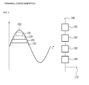
- FIG. 1 is a view illustrating a concept of a multilevel converter for converting power by switching a plurality of power converters.
- the multilevel converter converts Direct Current (DC) into Alternating Current (AC), and alternating current into direct current using the plurality of power converters.
- the multi-level converter may include a plurality of power converters 181, 182, 183, and 184 connected in series with each other as illustrated in FIG. 1 .
- the multilevel converter may include a plurality of phase legs, and each of the phase legs may include the plurality of power converters 181 to 184.
- the phase leg may be arranged between a DC terminal 160 and an AC terminal 170 to convert direct current into alternating current, or alternating current into direct current.
- an output of the phase leg may be the sum of outputs of the respective power converters 181 to 184.
- each of the power converters 181 to 184 may simply produce direct current.
- the output of the phase leg which is the sum of the outputs of the respective power converters 181 to 184, may have the form of alternating current through precisely controlling the switching time points of the respective power converters 181 to 184.
- a waveform 110 of alternating current illustrated in FIG. 1 may be obtained by approximating the output of the phase leg.
- the output 110 of the phase leg is configured by the sum of an output 150 of a first power converter, an output 140 of a second power converter, an output 130 of a third power converter, and an output 120 of a fourth power converter.
- the respective power converters 181 to 184 When the power converters 181 to 184 are switched from a deactivated state to an activated state, the respective power converters 181 to 184 produce the outputs. Accordingly, in order to configure the waveform 110 of alternating current by synthesizing the outputs of the respective power converters 181 to 184, the switching time points of the respective power converters 181 to 184 have to be precisely controlled.
- FIG. 2 is a circuit diagram illustrating a structure of a power converting apparatus according to an exemplary embodiment of the present invention.
- the power converting apparatus includes a plurality of phase legs, each of which includes a plurality of power converters. Furthermore, in order to control switching time points of the power converters 211 to 214 and 231 to 234, the power converting apparatus further includes a central controller 260 and sub-units 261 to 268 corresponding to the respective power converters 211 to 214 and 231 to 234.
- the central controller 260 generates a reference AC voltage.
- the central controller 260 transmits the generated reference AC voltage to the sub-units 261 to 268.
- the central controller 260 may allocate phase angles to the respective sub-units 261 to 268.
- the central controller 260 transmits the allocated phase angles to the respective sub-units 261 to 268.
- the sub-units 261 to 268 may individually create local switching carriers based on the received phase angles. According to an aspect, the respective sub-units 261 to 268 may create the local switching carriers having the same frequency. That is, the local switching carriers created by the respective sub-units 261 to 268 are sinusoidal waves having the same frequency and the phase angles determined under the control of the central controller 260.
- the respective sub-units 261 to 268 may control the power converters 211 to 214 and 231 to 234 such that the power converters 211 to 214 and 231 to 234 corresponding to the respective sub-units 261 to 268 are switched at intersection time points of the created local switching carriers and the reference AC voltage.
- the respective local switching carries have the same frequency, the phase angles thereof may be different from each other. Accordingly, the intersection time points of the respective local switching carriers and the reference AC voltage may be different from each other depending on the respective sub-units 261 to 268. Thus, switching time points of the power converters 211 to 214 and 231 to 234 corresponding to the respective sub-units 261 to 268 are determined to be different from each other.
- the switching time points of the respective power converters 211 to 214 and 231 to 234 may be determined such that the sum of outputs of the power converters 211 to 214 and 231 to 234 approximates to the AC waveform as illustrated in FIG. 1 .
- each of the power converters 211 to 214 and 231 to 234 may include a plurality of power electronic switches 270 connected in series with each other.
- the respective power converters 211 to 214 and 231 to 234 may include capacitors 221 to 224 and 241 to 244 connected in parallel with the power electronic switches 270 which are connected in series with each other.
- the central controller 260 allocates the phase angles to the respective sub-units 261 to 268 and generates the reference AC voltage, and the local switching carriers are created by the individual sub-units 261 to 268 having received the phase angles.
- the creation of the local switching carriers and the comparison of the local switching carriers and the reference AC voltage for the individual sub-units 261 to 268 are carried out by the respective sub-units 261 to 268, thereby reducing a burden of an operation for the central controller. Accordingly, precise control can be made using only the simple control algorithm.
- FIG. 3 is a block diagram illustrating a structure of a power converting apparatus according to an exemplary embodiment of the present invention.
- the power converting apparatus 300 may include a central controller310, sub-units 321 to 323, and power converters 331 to 333.
- the central controller 310 generates a reference AC voltage.
- the central controller 310 transmits the generated reference AC voltage to the sub-units 321 to 323. That is, the reference AC voltage is common in the sub-units 321 to 323.
- the reference AC voltage may be a sinusoidal wave.
- the central controller 310 allocates phase angles to the respective sub-units 321 to 323.
- the central controller 310 may allocate the phase angles to the sub-unit 321 to 323 such that the sum of outputs created by the respective power converters 331 to 333 to be switched by controlling the sub-units 321 to 323 has the AC waveform.
- the sub-units 321 to 323 receive the reference AC voltage and the phase angles.
- the respective sub-units 321 to 323 create local switching carriers using the received phase angles.
- the local switching carriers may be the same frequency of sinusoidal waves having different phases depending on the phase angles allocated by the central controller 310.
- the respective sub-units 321 to 323 compare the reference AC voltage with the created local switching carriers, and control switching of the power converters 331 to 333 corresponding to the respective sub-units 321 to 323 according to the result of the comparison.
- the respective sub-units 321 to 323 may control the power converters 331 to 333 to be switched.
- the plurality of power converters 331 to 333 may configure one phase leg 340.
- the power converters 331 to 333 included in the phase leg 340 may be connected in series with each other.
- the phase leg 340 is arranged between a DC connection terminal and an AC connection terminal of the power converting apparatus.
- the phase leg 340 may include M power converters.
- the central controller 310 may allocate the phase angles to the sub-units 321 to 323 such that differences between the phase angles allocated to the respective sub-units 321 to 323 are multiples of 2 ⁇ /M.
- each of the power converters 331 to 333 may include a plurality of power electronic switches.
- Each of the power electronic switches may be an element in which a transistor and a diode are connected in parallel with each other.
- the power electronic switches included in each of the power converters 331 to 333 may be connected in series with each other.
- each of the power converters 331 to 333 may include a capacitor connected in parallel with the power electronic switches which are connected in series with each other.
- FIG. 4 is a flowchart illustrating a power converting method according to an exemplary embodiment of the present invention.
- a central controller In step 410, a central controller generates a reference AC voltage.
- the central controller transmits the generated reference AC voltage to sub-units. That is, the reference AC voltage is common in the sub-units.
- the reference AC voltage may be a sinusoidal wave.
- the central controller allocates phase angles to the respective sub-units.
- the central controller may allocate the phase angles to the respective sub-units such that the sum of outputs created by the respective power converters to be switched by controlling the sub-units has the AC waveform.
- the respective sub-units receive the reference AC voltage and the phase angles.
- the respective sub-units create local switching carriers using the received phase angles.
- the local switching carriers may be the same frequency of sinusoidal waves having different phases depending on the phase angles allocated by the central controller.
- step 430 the respective sub-units compare the reference AC voltage with the created local switching carriers, and controls switching of the power converters corresponding to the respective sub-units according to the result of the comparison.
- the respective sub-units may control the power converters 331 to 333 to be switched.
- the plurality of power converters may configure one phase leg.
- the power converters included in the phase leg may be connected in series with each other.
- the phase leg is arranged between a DC connection terminal and an AC connection terminal of the power converting apparatus.
- the phase leg may include M power converters.
- the central controller may allocate the phase angles to the sub-units such that differences between the phase angles allocated to the respective sub-units are multiples of 2 ⁇ /M.
- each of the power converters may include a plurality of power electronic switches.
- Each of the power electronic switches may be an element in which a transistor and a diode are connected in parallel with each other.
- the power electronic switches included in each of the power converters may be connected in series with each other.
- each of the power converters may include a capacitor connected in parallel with the power electronic switches which are connected in series with each other.
- the methods according to the embodiments of the present invention may be implemented in the form of a program command which may be executed through various computer means, and may be recorded in a computer readable medium.
- the computer readable medium may include a program command, a data file, a data structure, and the like independently or in combination.
- the program command recorded in the medium may be things specially designed and configured for the present invention, or things that are well known to and can be used by those skilled in the computer software
Landscapes
- Engineering & Computer Science (AREA)
- Power Engineering (AREA)
- Inverter Devices (AREA)
- Rectifiers (AREA)
Abstract
Description
- The present invention relates to a technology for controlling a power converting system, and more particularly, to a technology for controlling the switching of power converters included in a power converting system.
- A multilevel converter may be used to convert direct current into alternating current, or alternating current into direct current. The multilevel converter in which a plurality of power converters are connected in series with each other precisely control operating time points or switching time points of the power converters to convert direct current into alternating current, or alternating current into direct current.
- The switching of the serially connected power converters is controlled depending on an input waveform, and outputs of the respective power converters are summed up according to the switching time points of the power converters to configure an output waveform. Accordingly, the technology for precisely controlling the switching time points of the respective power converters is emerging as a major issue in the commercialization of the multilevel converter.
- With an increase in the number of power converters included in the multilevel converter, a performance improvement such as reduction of high frequency distortion of the output waveform can be made. However, with the increase in the number of power converters, an algorithm for precisely controlling the switching time points of the respective power converters is complicated.
- An aspect of the present invention is to provide an apparatus and a method for converting power which can precisely control switching time points of power converters included in a multilevel converter.
- Another aspect of the present invention is to provide an apparatus and a method for converting power which can control switching time points of power converters included in a multilevel converter only with a small amount of operation.
- In accordance with one aspect of the present invention, an apparatus for converting power is provided. The apparatus includes: a central controller that generates a reference AC voltage; and a plurality of sub-units, wherein the central controller allocates phase angles to the respective sub-units, and the respective sub-units individually create local switching carriers based on the allocated phase angles, and controls switching of power converters corresponding to the respective sub-units according to a result of a comparison of the individually created local switching carriers and the reference AC voltage.
- The power converters may configure at least one phase leg, and, when M power converters are included in the phase leg, the central controller may allocate the phase angles such that differences between the allocated phase angles are multiples of 2π/M.
- The power converters included in the phase leg may be connected in series with each other.
- The phase leg may be arranged between a DC connection terminal and an AC connection terminal.
- The respective sub-units may compare the local switching carriers with the reference AC voltage, and may control the switching of the power converters corresponding to the respective sub-unit according to the result of the comparison.
- The power converters may include a plurality of power electronic switches connected in series with each other, and a capacitor connected in parallel with the power electronic switches.
- In accordance with another aspect of the present invention, a method of converting power is provided. The method includes: allocating phase angles to a plurality of sub-units, respectively, by a central controller; individually creating local switching carriers based on the allocated phase angles, by the respective sub-units; and controlling switching of power converters corresponding to the respective sub-units according to a result of a comparison of the individually created local switching carriers and a reference AC voltage, by the respective sub-units.
- The power converters may configure at least one phase leg, and, when M power converters are included in the phase leg, the central controller may allocate the phase angles such that differences between the allocated phase angles are multiples of 2π/M.
- The power converters included in the phase leg may be connected in series with each other.
- The phase leg may be arranged between a DC connection terminal and an AC connection terminal.
- The controlling of the switching may include comparing the local switching carriers with the reference AC voltage, and controlling the switching of the power converters corresponding to the respective sub-unit according to the result of the comparison.
- The power converters may include a plurality of power electronic switches connected in series with each other, and a capacitor connected in parallel with the power electronic switches.
- As described above, the present invention provides an apparatus and a method for converting power which can precisely control switching time points of power converters included in a multilevel converter.
- Furthermore, according to the embodiments of the present invention, switching time points of power converters included in a multilevel converter can be controlled only with a small amount of operation.
- The above and other objects, features and advantages of the present invention will be more apparent from the following detailed description taken in conjunction with the accompanying drawings, in which:
-
FIG. 1 is a view illustrating a concept of a multilevel converter for converting power by switching a plurality of power converters; -
FIG. 2 is a circuit diagram illustrating a structure of a power converting apparatus according to an exemplary embodiment of the present invention; -
FIG. 3 is a block diagram illustrating a structure of a power converting apparatus according to an exemplary embodiment of the present invention; and -
FIG. 4 is a flowchart illustrating a power converting method according to an exemplary embodiment of the present invention. - Hereinafter, an embodiment of the present invention will be described in detail with reference to the accompanying drawings.
-
FIG. 1 is a view illustrating a concept of a multilevel converter for converting power by switching a plurality of power converters. - The multilevel converter converts Direct Current (DC) into Alternating Current (AC), and alternating current into direct current using the plurality of power converters. According to an aspect, the multi-level converter may include a plurality of
power converters FIG. 1 . - According to an aspect, the multilevel converter may include a plurality of phase legs, and each of the phase legs may include the plurality of
power converters 181 to 184. The phase leg may be arranged between aDC terminal 160 and anAC terminal 170 to convert direct current into alternating current, or alternating current into direct current. In this case, an output of the phase leg may be the sum of outputs of therespective power converters 181 to 184. - According to an aspect, each of the
power converters 181 to 184 may simply produce direct current. However, the output of the phase leg, which is the sum of the outputs of therespective power converters 181 to 184, may have the form of alternating current through precisely controlling the switching time points of therespective power converters 181 to 184. - A
waveform 110 of alternating current illustrated inFIG. 1 may be obtained by approximating the output of the phase leg. Theoutput 110 of the phase leg is configured by the sum of anoutput 150 of a first power converter, an output 140 of a second power converter, anoutput 130 of a third power converter, and anoutput 120 of a fourth power converter. - When the
power converters 181 to 184 are switched from a deactivated state to an activated state, therespective power converters 181 to 184 produce the outputs. Accordingly, in order to configure thewaveform 110 of alternating current by synthesizing the outputs of therespective power converters 181 to 184, the switching time points of therespective power converters 181 to 184 have to be precisely controlled. -
FIG. 2 is a circuit diagram illustrating a structure of a power converting apparatus according to an exemplary embodiment of the present invention. - The power converting apparatus includes a plurality of phase legs, each of which includes a plurality of power converters. Furthermore, in order to control switching time points of the
power converters 211 to 214 and 231 to 234, the power converting apparatus further includes acentral controller 260 andsub-units 261 to 268 corresponding to therespective power converters 211 to 214 and 231 to 234. - According to an aspect, the
central controller 260 generates a reference AC voltage. Thecentral controller 260 transmits the generated reference AC voltage to thesub-units 261 to 268. Furthermore, thecentral controller 260 may allocate phase angles to therespective sub-units 261 to 268. Thecentral controller 260 transmits the allocated phase angles to therespective sub-units 261 to 268. - The
sub-units 261 to 268 may individually create local switching carriers based on the received phase angles. According to an aspect, therespective sub-units 261 to 268 may create the local switching carriers having the same frequency. That is, the local switching carriers created by therespective sub-units 261 to 268 are sinusoidal waves having the same frequency and the phase angles determined under the control of thecentral controller 260. - The
respective sub-units 261 to 268 may control thepower converters 211 to 214 and 231 to 234 such that thepower converters 211 to 214 and 231 to 234 corresponding to therespective sub-units 261 to 268 are switched at intersection time points of the created local switching carriers and the reference AC voltage. - Although the respective local switching carries have the same frequency, the phase angles thereof may be different from each other. Accordingly, the intersection time points of the respective local switching carriers and the reference AC voltage may be different from each other depending on the
respective sub-units 261 to 268. Thus, switching time points of thepower converters 211 to 214 and 231 to 234 corresponding to therespective sub-units 261 to 268 are determined to be different from each other. - According to an aspect, the switching time points of the
respective power converters 211 to 214 and 231 to 234 may be determined such that the sum of outputs of thepower converters 211 to 214 and 231 to 234 approximates to the AC waveform as illustrated inFIG. 1 . - As illustrated in
FIG. 2 , each of thepower converters 211 to 214 and 231 to 234 may include a plurality of powerelectronic switches 270 connected in series with each other. In this case, therespective power converters 211 to 214 and 231 to 234 may includecapacitors 221 to 224 and 241 to 244 connected in parallel with the powerelectronic switches 270 which are connected in series with each other. - According to the embodiment illustrated in
FIG. 2 , thecentral controller 260 allocates the phase angles to therespective sub-units 261 to 268 and generates the reference AC voltage, and the local switching carriers are created by theindividual sub-units 261 to 268 having received the phase angles. - That is, the creation of the local switching carriers and the comparison of the local switching carriers and the reference AC voltage for the
individual sub-units 261 to 268 are carried out by therespective sub-units 261 to 268, thereby reducing a burden of an operation for the central controller. Accordingly, precise control can be made using only the simple control algorithm. -
FIG. 3 is a block diagram illustrating a structure of a power converting apparatus according to an exemplary embodiment of the present invention. - The
power converting apparatus 300 may include a central controller310, sub-units 321 to 323, andpower converters 331 to 333. - The
central controller 310 generates a reference AC voltage. Thecentral controller 310 transmits the generated reference AC voltage to the sub-units 321 to 323. That is, the reference AC voltage is common in the sub-units 321 to 323. According to an aspect, the reference AC voltage may be a sinusoidal wave. - Furthermore, the
central controller 310 allocates phase angles to therespective sub-units 321 to 323. According to an aspect, thecentral controller 310 may allocate the phase angles to the sub-unit 321 to 323 such that the sum of outputs created by therespective power converters 331 to 333 to be switched by controlling the sub-units 321 to 323 has the AC waveform. - The sub-units 321 to 323 receive the reference AC voltage and the phase angles. The
respective sub-units 321 to 323 create local switching carriers using the received phase angles. According to an aspect, the local switching carriers may be the same frequency of sinusoidal waves having different phases depending on the phase angles allocated by thecentral controller 310. - The
respective sub-units 321 to 323 compare the reference AC voltage with the created local switching carriers, and control switching of thepower converters 331 to 333 corresponding to therespective sub-units 321 to 323 according to the result of the comparison. - According to an aspect, every time the local switching carriers intersect with the reference AC voltage, the
respective sub-units 321 to 323 may control thepower converters 331 to 333 to be switched. - According to an aspect, the plurality of
power converters 331 to 333 may configure onephase leg 340. Thepower converters 331 to 333 included in thephase leg 340 may be connected in series with each other. Thephase leg 340 is arranged between a DC connection terminal and an AC connection terminal of the power converting apparatus. - According to an aspect, the
phase leg 340 may include M power converters. In this case, thecentral controller 310 may allocate the phase angles to the sub-units 321 to 323 such that differences between the phase angles allocated to therespective sub-units 321 to 323 are multiples of 2π/M. - According to an aspect, each of the
power converters 331 to 333 may include a plurality of power electronic switches. Each of the power electronic switches may be an element in which a transistor and a diode are connected in parallel with each other. Furthermore, the power electronic switches included in each of thepower converters 331 to 333 may be connected in series with each other. Moreover, each of thepower converters 331 to 333 may include a capacitor connected in parallel with the power electronic switches which are connected in series with each other. -
FIG. 4 is a flowchart illustrating a power converting method according to an exemplary embodiment of the present invention. - In
step 410, a central controller generates a reference AC voltage. The central controller transmits the generated reference AC voltage to sub-units. That is, the reference AC voltage is common in the sub-units. According to an aspect, the reference AC voltage may be a sinusoidal wave. - In
step 410, the central controller allocates phase angles to the respective sub-units. According to an aspect, the central controller may allocate the phase angles to the respective sub-units such that the sum of outputs created by the respective power converters to be switched by controlling the sub-units has the AC waveform. - In
step 420, the respective sub-units receive the reference AC voltage and the phase angles. The respective sub-units create local switching carriers using the received phase angles. According to an aspect, the local switching carriers may be the same frequency of sinusoidal waves having different phases depending on the phase angles allocated by the central controller. - In
step 430, the respective sub-units compare the reference AC voltage with the created local switching carriers, and controls switching of the power converters corresponding to the respective sub-units according to the result of the comparison. - According to an aspect, every time the local switching carriers intersect with the reference AC voltage, the respective sub-units may control the
power converters 331 to 333 to be switched. - According to an aspect, the plurality of power converters may configure one phase leg. The power converters included in the phase leg may be connected in series with each other. The phase leg is arranged between a DC connection terminal and an AC connection terminal of the power converting apparatus.
- According to an aspect, the phase leg may include M power converters. In this case, the central controller may allocate the phase angles to the sub-units such that differences between the phase angles allocated to the respective sub-units are multiples of 2π/M.
- According to an aspect, each of the power converters may include a plurality of power electronic switches. Each of the power electronic switches may be an element in which a transistor and a diode are connected in parallel with each other. Furthermore, the power electronic switches included in each of the power converters may be connected in series with each other. Moreover, each of the power converters may include a capacitor connected in parallel with the power electronic switches which are connected in series with each other.
- The methods according to the embodiments of the present invention may be implemented in the form of a program command which may be executed through various computer means, and may be recorded in a computer readable medium. The computer readable medium may include a program command, a data file, a data structure, and the like independently or in combination. The program command recorded in the medium may be things specially designed and configured for the present invention, or things that are well known to and can be used by those skilled in the computer software
- Although the present invention has been described by the restricted embodiments and the drawings as described above, the present invention is not limited to the aforementioned embodiments, and various modifications and alterations can be made from the descriptions by those skilled in the art to which the present invention pertains.
- Accordingly, the scope of the present invention should not be determined by the above-described embodiments, and should be determined by not only the following claims but also their equivalents.
Claims (13)
- An apparatus for converting power comprising:a central controller that generates a reference AC voltage; anda plurality of sub-units,wherein the central controller allocates phase angles to the respective sub-units, and the respective sub-units individually create local switching carriers based on the allocated phase angles, and controls switching of power converters corresponding to the respective sub-units according to a result of a comparison of the individually created local switching carriers and the reference AC voltage.
- The apparatus of claim 1, wherein the power converters configure at least one phase leg, and, when M power converters are included in the phase leg, the central controller allocates the phase angles such that differences between the allocated phase angles are multiples of 2π/M.
- The apparatus of claim 2, wherein the power converters included in the phase leg are connected in series with each other.
- The apparatus of claim 2, wherein the phase leg is arranged between a DC connection terminal and an AC connection terminal.
- The apparatus of claim 1, wherein the respective sub-units control the switching of the power converters corresponding to the respective sub-unit when the local switching carriers intersect with the reference AC voltage.
- The apparatus of claim 1, wherein the power converters comprise a plurality of power electronic switches connected in series with each other, and a capacitor connected in parallel with the power electronic switches.
- A method of converting power comprises:allocating phase angles to a plurality of sub-units, respectively, by a central controller;individually creating local switching carriers based on the allocated phase angles, by the respective sub-units; andcontrolling switching of power converters corresponding to the respective sub-units according to a result of a comparison of the individually created local switching carriers and a reference AC voltage, by the respective sub-units.
- The method of claim 7, wherein the power converters configure at least one phase leg, and, when M power converters are included in the phase leg, the central controller allocates the phase angles such that differences between the allocated phase angles are multiples of 2π/M.
- The method of claim 8, wherein the power converters included in the phase leg are connected in series with each other.
- The method of claim 8, wherein the phase leg is arranged between a DC connection terminal and an AC connection terminal.
- The method of claim 7, wherein the controlling of the switching comprises:controlling the switching of the power converters corresponding to the respective sub-unit when the local switching carriers intersect with the reference AC voltage.
- The method of claim 7, wherein the power converters comprise a plurality of power electronic switches connected in series with each other, and a capacitor connected in parallel with the power electronic switches.
- A computer readable recording medium in which a program for executing the method of any one of claims 7 to 12 is recorded.
Applications Claiming Priority (2)
| Application Number | Priority Date | Filing Date | Title |
|---|---|---|---|
| KR1020110133006A KR101251166B1 (en) | 2011-12-12 | 2011-12-12 | Unit and method for controlling module switching of power transform system |
| PCT/KR2012/010786 WO2013089425A1 (en) | 2011-12-12 | 2012-12-12 | Device and method for controlling module switching of power conversion system |
Publications (2)
| Publication Number | Publication Date |
|---|---|
| EP2793383A1 true EP2793383A1 (en) | 2014-10-22 |
| EP2793383A4 EP2793383A4 (en) | 2016-03-23 |
Family
ID=48442437
Family Applications (1)
| Application Number | Title | Priority Date | Filing Date |
|---|---|---|---|
| EP12856846.6A Withdrawn EP2793383A4 (en) | 2011-12-12 | 2012-12-12 | DEVICE AND METHOD FOR CONTROLLING THE SWITCHING OF MODULES OF AN ENERGY CONVERSION SYSTEM |
Country Status (4)
| Country | Link |
|---|---|
| US (1) | US9438098B2 (en) |
| EP (1) | EP2793383A4 (en) |
| KR (1) | KR101251166B1 (en) |
| WO (1) | WO2013089425A1 (en) |
Cited By (1)
| Publication number | Priority date | Publication date | Assignee | Title |
|---|---|---|---|---|
| EP4010976A1 (en) * | 2019-08-07 | 2022-06-15 | Abb Schweiz Ag | Control of an icbt converter |
Families Citing this family (3)
| Publication number | Priority date | Publication date | Assignee | Title |
|---|---|---|---|---|
| US9941813B2 (en) | 2013-03-14 | 2018-04-10 | Solaredge Technologies Ltd. | High frequency multi-level inverter |
| US9318974B2 (en) | 2014-03-26 | 2016-04-19 | Solaredge Technologies Ltd. | Multi-level inverter with flying capacitor topology |
| EP3694098B1 (en) | 2017-10-04 | 2021-06-09 | Mitsubishi Electric Corporation | Power conversion apparatus |
Family Cites Families (6)
| Publication number | Priority date | Publication date | Assignee | Title |
|---|---|---|---|---|
| EP0977348B1 (en) * | 1998-07-30 | 2009-03-11 | Koninklijke Philips Electronics N.V. | Power amplifier with soft switching and multilevel switching cells |
| RU2388133C2 (en) * | 2005-09-09 | 2010-04-27 | Сименс Энерджи Энд Отомейшн, Инк. | System and method for reduction of harmonics effect at system of energy delivery |
| KR100716310B1 (en) | 2006-03-06 | 2007-05-09 | 문채주 | Multilevel Inverter Using Phase Shifting Technique and Its Control Method |
| US8385097B2 (en) * | 2008-01-08 | 2013-02-26 | Abb Technology Ag | Method for controlling a voltage source converter and a voltage converting apparatus |
| DE102008014898B4 (en) * | 2008-03-19 | 2018-09-27 | Siemens Aktiengesellschaft | Method for controlling a multiphase power converter with distributed energy stores at low output frequencies |
| EP2369725B1 (en) * | 2010-03-25 | 2012-09-26 | ABB Schweiz AG | Short circuiting unit |
-
2011
- 2011-12-12 KR KR1020110133006A patent/KR101251166B1/en active Active
-
2012
- 2012-12-12 WO PCT/KR2012/010786 patent/WO2013089425A1/en not_active Ceased
- 2012-12-12 EP EP12856846.6A patent/EP2793383A4/en not_active Withdrawn
- 2012-12-12 US US14/364,494 patent/US9438098B2/en active Active
Cited By (1)
| Publication number | Priority date | Publication date | Assignee | Title |
|---|---|---|---|---|
| EP4010976A1 (en) * | 2019-08-07 | 2022-06-15 | Abb Schweiz Ag | Control of an icbt converter |
Also Published As
| Publication number | Publication date |
|---|---|
| EP2793383A4 (en) | 2016-03-23 |
| US9438098B2 (en) | 2016-09-06 |
| WO2013089425A1 (en) | 2013-06-20 |
| US20140376288A1 (en) | 2014-12-25 |
| KR101251166B1 (en) | 2013-04-04 |
Similar Documents
| Publication | Publication Date | Title |
|---|---|---|
| US10560037B2 (en) | Apparatus and method for control of multi-inverter power converter | |
| EP2894780B1 (en) | Multilevel converter systems and methods with reduced common mode voltage | |
| CN202160117U (en) | Power conversion system | |
| EP2214301B1 (en) | Power conversion systems and methods for controlling harmonic distortion | |
| US11018598B2 (en) | System and method for controlling switching network of a power regulation circuit | |
| US9071166B2 (en) | Power converter with surge voltage suppression | |
| KR101711947B1 (en) | Modular multilevel converter | |
| US10644609B2 (en) | Nestable single cell structure for use in a power conversion system | |
| CN107425758B (en) | Method and system for controlling a motor control device | |
| EP3682538B1 (en) | Pulse width modulation control for a multilevel converter | |
| EP2533412A2 (en) | Solar power conversion apparatus | |
| JPWO2013080465A1 (en) | INVERTER DEVICE CONTROL METHOD AND INVERTER DEVICE | |
| US9438098B2 (en) | Apparatus and method for controlling module switching of power converting system | |
| US20180175627A1 (en) | Space vector modulation in aerospace applications | |
| JP5072097B2 (en) | Three-phase voltage type inverter system | |
| JP2019106825A (en) | Power conversion device | |
| JP5494618B2 (en) | Power converter | |
| CN102263518A (en) | Power supply circuit | |
| JP2016178760A (en) | Multiplexable single cell structure for use in power conversion system | |
| JP6518693B2 (en) | POWER CONVERTER AND CONTROL METHOD OF POWER CONVERTER | |
| JP6303908B2 (en) | Neutral point potential control method for single-phase NPC inverter | |
| Ramos et al. | Enhanced implementation of a state machine-based decoder for optimal modulation of multilevel converters | |
| KR102269005B1 (en) | Generator system | |
| EP4611246A1 (en) | Inverter, inverter control method, and program | |
| JP6552388B2 (en) | Control apparatus and control method of current source power converter |
Legal Events
| Date | Code | Title | Description |
|---|---|---|---|
| PUAI | Public reference made under article 153(3) epc to a published international application that has entered the european phase |
Free format text: ORIGINAL CODE: 0009012 |
|
| 17P | Request for examination filed |
Effective date: 20140709 |
|
| AK | Designated contracting states |
Kind code of ref document: A1 Designated state(s): AL AT BE BG CH CY CZ DE DK EE ES FI FR GB GR HR HU IE IS IT LI LT LU LV MC MK MT NL NO PL PT RO RS SE SI SK SM TR |
|
| DAX | Request for extension of the european patent (deleted) | ||
| RA4 | Supplementary search report drawn up and despatched (corrected) |
Effective date: 20160224 |
|
| RIC1 | Information provided on ipc code assigned before grant |
Ipc: H02M 7/483 20070101ALI20160218BHEP Ipc: H02M 1/08 20060101AFI20160218BHEP Ipc: H02M 7/23 20060101ALI20160218BHEP |
|
| STAA | Information on the status of an ep patent application or granted ep patent |
Free format text: STATUS: EXAMINATION IS IN PROGRESS |
|
| 17Q | First examination report despatched |
Effective date: 20170518 |
|
| RAP1 | Party data changed (applicant data changed or rights of an application transferred) |
Owner name: HYOSUNG HEAVY INDUSTRIES CORPORATION |
|
| STAA | Information on the status of an ep patent application or granted ep patent |
Free format text: STATUS: THE APPLICATION IS DEEMED TO BE WITHDRAWN |
|
| 18D | Application deemed to be withdrawn |
Effective date: 20191203 |