EP2793289A2 - Battery module - Google Patents
Battery module Download PDFInfo
- Publication number
- EP2793289A2 EP2793289A2 EP20140160193 EP14160193A EP2793289A2 EP 2793289 A2 EP2793289 A2 EP 2793289A2 EP 20140160193 EP20140160193 EP 20140160193 EP 14160193 A EP14160193 A EP 14160193A EP 2793289 A2 EP2793289 A2 EP 2793289A2
- Authority
- EP
- European Patent Office
- Prior art keywords
- housing
- bottom plate
- bending portion
- battery
- side plate
- Prior art date
- Legal status (The legal status is an assumption and is not a legal conclusion. Google has not performed a legal analysis and makes no representation as to the accuracy of the status listed.)
- Granted
Links
Images



Classifications
-
- H—ELECTRICITY
- H01—ELECTRIC ELEMENTS
- H01M—PROCESSES OR MEANS, e.g. BATTERIES, FOR THE DIRECT CONVERSION OF CHEMICAL ENERGY INTO ELECTRICAL ENERGY
- H01M50/00—Constructional details or processes of manufacture of the non-active parts of electrochemical cells other than fuel cells, e.g. hybrid cells
- H01M50/20—Mountings; Secondary casings or frames; Racks, modules or packs; Suspension devices; Shock absorbers; Transport or carrying devices; Holders
-
- H—ELECTRICITY
- H01—ELECTRIC ELEMENTS
- H01M—PROCESSES OR MEANS, e.g. BATTERIES, FOR THE DIRECT CONVERSION OF CHEMICAL ENERGY INTO ELECTRICAL ENERGY
- H01M50/00—Constructional details or processes of manufacture of the non-active parts of electrochemical cells other than fuel cells, e.g. hybrid cells
- H01M50/20—Mountings; Secondary casings or frames; Racks, modules or packs; Suspension devices; Shock absorbers; Transport or carrying devices; Holders
- H01M50/204—Racks, modules or packs for multiple batteries or multiple cells
- H01M50/207—Racks, modules or packs for multiple batteries or multiple cells characterised by their shape
- H01M50/209—Racks, modules or packs for multiple batteries or multiple cells characterised by their shape adapted for prismatic or rectangular cells
-
- H—ELECTRICITY
- H01—ELECTRIC ELEMENTS
- H01M—PROCESSES OR MEANS, e.g. BATTERIES, FOR THE DIRECT CONVERSION OF CHEMICAL ENERGY INTO ELECTRICAL ENERGY
- H01M50/00—Constructional details or processes of manufacture of the non-active parts of electrochemical cells other than fuel cells, e.g. hybrid cells
- H01M50/20—Mountings; Secondary casings or frames; Racks, modules or packs; Suspension devices; Shock absorbers; Transport or carrying devices; Holders
- H01M50/262—Mountings; Secondary casings or frames; Racks, modules or packs; Suspension devices; Shock absorbers; Transport or carrying devices; Holders with fastening means, e.g. locks
-
- H—ELECTRICITY
- H01—ELECTRIC ELEMENTS
- H01M—PROCESSES OR MEANS, e.g. BATTERIES, FOR THE DIRECT CONVERSION OF CHEMICAL ENERGY INTO ELECTRICAL ENERGY
- H01M50/00—Constructional details or processes of manufacture of the non-active parts of electrochemical cells other than fuel cells, e.g. hybrid cells
- H01M50/50—Current conducting connections for cells or batteries
-
- B—PERFORMING OPERATIONS; TRANSPORTING
- B65—CONVEYING; PACKING; STORING; HANDLING THIN OR FILAMENTARY MATERIAL
- B65D—CONTAINERS FOR STORAGE OR TRANSPORT OF ARTICLES OR MATERIALS, e.g. BAGS, BARRELS, BOTTLES, BOXES, CANS, CARTONS, CRATES, DRUMS, JARS, TANKS, HOPPERS, FORWARDING CONTAINERS; ACCESSORIES, CLOSURES, OR FITTINGS THEREFOR; PACKAGING ELEMENTS; PACKAGES
- B65D2585/00—Containers, packaging elements or packages specially adapted for particular articles or materials
- B65D2585/68—Containers, packaging elements or packages specially adapted for particular articles or materials for machines, engines, or vehicles in assembled or dismantled form
- B65D2585/86—Containers, packaging elements or packages specially adapted for particular articles or materials for machines, engines, or vehicles in assembled or dismantled form for electrical components
-
- H—ELECTRICITY
- H01—ELECTRIC ELEMENTS
- H01M—PROCESSES OR MEANS, e.g. BATTERIES, FOR THE DIRECT CONVERSION OF CHEMICAL ENERGY INTO ELECTRICAL ENERGY
- H01M50/00—Constructional details or processes of manufacture of the non-active parts of electrochemical cells other than fuel cells, e.g. hybrid cells
- H01M50/20—Mountings; Secondary casings or frames; Racks, modules or packs; Suspension devices; Shock absorbers; Transport or carrying devices; Holders
- H01M50/271—Lids or covers for the racks or secondary casings
-
- H—ELECTRICITY
- H01—ELECTRIC ELEMENTS
- H01M—PROCESSES OR MEANS, e.g. BATTERIES, FOR THE DIRECT CONVERSION OF CHEMICAL ENERGY INTO ELECTRICAL ENERGY
- H01M50/00—Constructional details or processes of manufacture of the non-active parts of electrochemical cells other than fuel cells, e.g. hybrid cells
- H01M50/20—Mountings; Secondary casings or frames; Racks, modules or packs; Suspension devices; Shock absorbers; Transport or carrying devices; Holders
- H01M50/289—Mountings; Secondary casings or frames; Racks, modules or packs; Suspension devices; Shock absorbers; Transport or carrying devices; Holders characterised by spacing elements or positioning means within frames, racks or packs
-
- Y—GENERAL TAGGING OF NEW TECHNOLOGICAL DEVELOPMENTS; GENERAL TAGGING OF CROSS-SECTIONAL TECHNOLOGIES SPANNING OVER SEVERAL SECTIONS OF THE IPC; TECHNICAL SUBJECTS COVERED BY FORMER USPC CROSS-REFERENCE ART COLLECTIONS [XRACs] AND DIGESTS
- Y02—TECHNOLOGIES OR APPLICATIONS FOR MITIGATION OR ADAPTATION AGAINST CLIMATE CHANGE
- Y02E—REDUCTION OF GREENHOUSE GAS [GHG] EMISSIONS, RELATED TO ENERGY GENERATION, TRANSMISSION OR DISTRIBUTION
- Y02E60/00—Enabling technologies; Technologies with a potential or indirect contribution to GHG emissions mitigation
- Y02E60/10—Energy storage using batteries
Definitions
- An aspect of the present invention relates to a battery module for absorbing a width tolerance.
- the high-power battery module is configured as a large-capacity battery module manufactured by connecting a plurality of battery cells in series so as to be used for driving devices, e.g., motors of electric vehicles and the like, which require high power.
- the battery module includes a plurality of battery cells in consideration of output voltage and current.
- the battery module also includes a frame for firmly fixing the battery cells. In a case where there occurs a tolerance with which the width of the battery cells is greater or smaller than that of the frame, the battery cells cannot be firmly fixed by the frame.
- Embodiments provide a housing for closely adhering to battery cells and a battery module in which a frame is adhered closely to battery cells even when there occurs a tolerance with which the width of the battery cells is greater or smaller than that of the frame, so that the battery cells can be firmly fixed by the frame.
- a battery module comprising: a plurality of battery cells and a housing for accommodating a plurality of battery cells.
- the housing comprises a pair of side plates, a bottom plate and at least one bending portion between a respective one of the side plates and the bottom plate wherein the at least one bending portion is configured to bias the side plate toward an interval between the pair of side plates.
- the battery module comprises the plurality of battery cells and a housing accommodating the battery cells.
- the housing of the battery module comprises a side plate, a bottom plate, and a bending portion between the side plate and the bottom plate, wherein the bending portion protrudes outwardly at least from the side plate.
- the at least one bending portion may have a round shape.
- the round shape When the length of the battery cell in the width direction is smaller than the interval between the pair of side plates, the round shape may be changed by a force applied in the side direction of the battery cell from the outside, and the side plate may be horizontally moved in the side direction of the battery cell.
- the round shape When the length of the battery cell in the width direction is greater than the interval between the pair of side plates, the round shape may be changed by a force applied in the opposite direction to the side of the battery cell from the outside, and the side plate may be horizontally moved in the opposite direction to the side of the battery cell.
- the bending portion may include a first extending portion extended from the bottom plate, and a second extending portion extended diagonally with respect to the side direction of the battery cell from the first extending portion.
- the angle formed between the first and second extending portions may be decreased by the force applied in the side direction of the battery cell from the outside, and the side plate may be horizontally moved in the side direction of the battery cell.
- the angle formed between the first and second extending portions may be increased by the force applied in the side direction of the battery cell from the outside, and the side plate may be horizontally moved in the opposite direction to the side of the battery cell.
- the side plate may be formed to extend in the direction parallel with the side of the battery cell from the second extending portion.
- the bending portion may further include a cut-away groove formed between the first and second extending portions.
- the battery module may further include a pair of end plates respectively coming in surface contact with the outermost battery cells among the battery cells, and a top cover covering tops of the battery cells.
- One end of the side plate may be fastened to one end of the end plate through laser welding.
- the side plate may include at least one first fastening portion fastened to the top cover, and the bottom plate may include at least one first fastening portion fastened to the end plate.
- the top cover may include at least one first fastening portion fastened to the side plate, and at least one second fastening portion fastened to the end plate.
- the end plate may include at least one first fastening portion fastened to the top cover, and at least one second fastening portion fastened to the bottom plate.
- the first fastening portion of the side plate and the first fastening portion of the top cover, the second fastening portion of the top cover and the first fastening portion of the end plate, or the second fastening portion of the end plate and the first fastening portion of the bottom plate may be fastened to each other by the medium of a fastening member or through laser welding.
- the fastening member may be a bolt-nut or stud.
- the side plate may have at least one opening formed therein.
- a frame can come in surface contact with battery cells, regardless of the size of the battery cells in the width direction, thereby firmly fixing the battery cells. Further advantageous embodiments are specified in the claims. Further advantageous embodiments are specified in the dependent claims.
- FIG. 1 is a perspective view schematically showing a battery module according to an embodiment of the present invention.
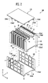
- FIG. 2 is an exploded perspective view of FIG. 1 .
- the battery module 100 includes a plurality of battery cells 10 arranged in one direction and each having electrode terminals 11 and 12.
- the battery cells 10 are arranged so that wide surfaces of adjacent battery cells 10 face each other.
- Each of the battery cells 10 constituting the battery module 100 may be manufactured by accommodating an electrode assembly and an electrolyte in a battery case and then sealing the battery case in which the electrode assembly is accommodated, using a cap plate 14.
- the electrode assembly includes a positive electrode plate and a negative electrode plate and a separator interposed between these electrode plates.
- the cap plate 14 may be provided with electrode terminals protruded to the outside thereof.
- the electrode terminals may be positive and negative electrode terminals 11 and 12 respectively connected to the positive and negative electrode plates.
- the positive and negative electrode plates may generate electrochemical energy by reacting with the electrolyte. In this case, the generated energy is transferred to the outside of the battery cell 10 through the positive and negative electrode terminals 11 and 12.
- a vent is provided in the cap plate 14 between the positive and negative electrode terminals 11 and 12, so as to serve as a passage through which gas is exhausted to the outside of the battery cell 10.
- the battery cell 10 is a prismatic secondary battery
- the present invention is not limited thereto and may be applied to various types of batteries including a lithium polymer battery, a cylindrical battery, and the like.
- a housing member 110 includes a pair of end plates 112 respectively coming in surface contact with the outermost battery cells 10 among the plurality of battery cells 10, a pair of side plates 113 disposed between the pair of end plates 112, and coming in surface contact with surfaces of the battery cells 10, and a bottom plate 114 facing bottoms of the battery cells 10.
- the bottom plate 114 may be extended in the vertical direction from the pair of side plates 113 so as to be integrally formed with the side plates 113.
- the side plate 113 has at least one first fastening portion 113a1 fastened to a top cover 115, and a first fastening hole 113a2 is formed in the first fastening portion 113a of the side plate 113.
- the bottom plate 114 has at least one fastening portion 114a1 fastened to the end plate 112, and a fastening hole 114a2 is formed in the fastening portion 114a1 of the bottom plate 114.
- the top cover 115 has at least one first fastening portion 115a1 fastened to the side plate 113 and at least one second fastening portion 115b1 fastened to the end plate 112.
- First and second fastening holes 115a2 and 115b2 are respectively formed in the first and second fastening portions 115a1 and 115b1 of the top cover 115.
- the end plate 112 has at least one first fastening portion 112a1 fastened to the top cover 115 and at least one second fastening portion 112c1 fastened to the bottom plate 114.
- First and second fastening holes 112a2 and 112c2 are respectively formed in the first and second fastening portions 112a1 and 112c1 of the end plate 112.
- the first and second end plates 112 are disposed to come in surface contact with the respective outermost battery cells 10, thereby pressurizing the plurality of battery cells 10 to the inside thereof.
- the side plate 113 connects the first and second end plates 112 to each other. One end of the side plate 113 is fastened to the first end plate 112, and the other end of the side plate 113 is fastened to the second end plate 112. In this case, the first and second end plates 112 may be fasted to the side plate 113 through laser welding.
- the side plates 113 provide a space in which the plurality of battery cells 10 can be aligned by connecting the first and second end plates 112 to each other, and simultaneously support both sides of the battery cells 10. Referring to FIG. 2 , it has been described in this embodiment that the side plates 113 support both the sides of the battery cells 10 and have openings O for a coolant flow path, which are formed therein. However, the shape and the like of the side plate 113 may be freely modified according to the design of the battery module 100.
- the battery cells 10 are fixed in the space defined by the first and second end plates 112 and the side plates 113 so as not to be easily moved by an external impact.
- a barrier 30 may be interposed between adjacent battery cells 10.
- a spacer (not shown) is provided in each barrier 30, so as to space apart the plurality of adjacent battery cells 10 from each other and to form a space between the battery cells 10. Accordingly, it is possible to provide the flow path of a coolant for cooling the battery cells 10.
- the battery module 100 may further include a bus-bar 20 connecting the positive and negative electrodes 11 and 12 of the adjacent battery cells 10, and a shielding wall 21 surrounding adjacent bus-bars 20.
- the shielding wall 21 may be provided to partition a plurality of bus-bars 20 electrically connecting the electrode terminals 11 and 12 of the adjacent battery cells 10. Thus, it is possible to prevent a short circuit between adjacent bus-bars 20 and to prevent a short circuit caused by an electric conductor made of metal such as a bolt-nut, which is a material used in the battery module 100.
- the fastening portion 113a1, 114a1, 115a1, 115b1, 112a1 or 112c1 and the fastening hole 113a2, 114a2, 115a2, 115b2, 112a2 or 112c2 may be fastened to each other by a fastening member such as a bolt-nut or stud.
- a fastening member such as a bolt-nut or stud.
- the fastening portion and the fastening hole may be fastened to each other through welding.
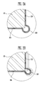
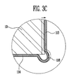
- FIGS. 3A to 3C are enlarged sectional views showing region A of FIG. 1 .
- a bending portion 116 is formed in a region where the side plate 113 and the bottom plate 114 are connected to each other.
- the bending portion 116 has a sectional shape protruded outward so that the side plate 113 can be moved in a side direction of the battery cell 10 or in the opposite direction thereto.
- the sectional shape of the bending portion 116 may be a round shape.
- the side plate 113 may be horizontally moved in a side direction of the battery cell 10 through a change in the bending portion 116 as shown in FIG. 3B . That is, the side plate 113 is moved in the side direction of the battery cell 10 by a force applied from the outside, thereby coming in surface contact with the side of the battery cell 10.
- the side plate 113 may be moved in the opposite direction to the side direction of the battery cell 10 through a change in the bending portion 116 as shown in FIG. 3C . That is, the battery cell 10 is inserted into a space formed between the side plate 113 and the bottom plate 114 through the horizontal movement of the side plate 113, thereby assembling the battery pack. When the battery cell 10 is inserted into the space formed between the side plate 113 and the bottom plate 114, the side plate 113 comes in surface contact with the side of the battery cell 10.
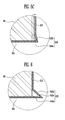
- FIGS. 4A and 4B are partial enlarged sectional views showing a front lower portion of the battery module when no bending portion is formed.
- a side plate 413 may be formed to protrude in the vertical direction from a bottom plate 414.
- the bending portion 116 is formed in the region where the side plate 113 and the bottom plate 114 are connected to each other as described in FIG. 3 , so that the side of the battery cell 10 can come in surface contact with the side plate 113 even when the width direction of the battery cell 10 is not constant.
- FIGS. 5A to 5C are partial enlarged sectional views showing a front lower portion of a battery module according to another embodiment of the present invention.
- a bending portion 516 having a sectional shape convex to the outside of the battery module is formed in the region where a side plate 513 and a bottom plate 514 are connected to each other.
- the bending portion 516 may include a first extending portion 516a extended from the bottom plate 514, and a second extending portion 516b extended diagonally with respect to the side direction of the battery cell 10 from the first extending portion 516a.
- the side plates 513 may be formed to extend in the direction parallel with the side of the battery cell 10 from the second extending portion 516b.
- the first extending portion 516a is formed to extend in the direction parallel with the bottom plate 514, the first extending portion 516a may be formed to extend while having an inclination of 90 degrees or less.
- the angle formed between the first and second extending portions 516a and 516b may be decreased through a force applied in the side direction of the battery cell 10 from the outside as shown in FIG. 5B . Accordingly, the side plate 513 is horizontally moved in the side direction of the battery cell 10, so that the side plate 513 can come in surface contact with the side of the battery cell 10.
- the angle formed between the first and second extending portions 516a and 516b can be increased through a force applied in the opposite direction to the side of the battery cell 10 from the outside as shown in 5C.
- the side plate 513 is horizontally moved in the opposite direction to the side of the battery cell 10.
- FIG. 6 is a partial enlarged sectional view showing a front lower portion of a battery module according to still another embodiment of the present invention.
- components in this embodiment except a bending portion 516 are identical to those in the embodiment shown in FIG. 5 . Therefore, like components are designated by like reference numerals, and their detailed descriptions will be omitted.
- the bending portion 516 may include a first extending portion 516a extended from the bottom plate 514, a second extending portion 516b extended diagonally with respect to the side direction of the battery cell 10 from the first extending portion 516a, and a cut-away groove 516c formed between the first and second extending portions 516a and 516b.
- the cut-away groove 516c may perform a function of facilitating a change in the second extending portion 516b in the lateral direction.
- the bending portion 116 or 516 enabling the side plate 113 or 513 to be moved is formed in the region where the side plate 113 or 513 and the bottom plate 114 or 514 are connected to each other, so that the side plate 113 or 513 can come in surface contact with the side of the battery cell 10 even when there occurs a tolerance between the length of the battery cell 10 in the width direction and the interval between the pair of side plates 113 or 513. That is, a frame can come in surface contact with the battery cell, regardless of the length of the battery cell in the width direction, so that the battery cells can be firmly fixed by the frame.
Landscapes
- Chemical & Material Sciences (AREA)
- Chemical Kinetics & Catalysis (AREA)
- Electrochemistry (AREA)
- General Chemical & Material Sciences (AREA)
- Battery Mounting, Suspending (AREA)
Abstract
Description
- An aspect of the present invention relates to a battery module for absorbing a width tolerance.
- A high-power battery module using a non-aqueous electrolyte with high energy density has recently been developed. The high-power battery module is configured as a large-capacity battery module manufactured by connecting a plurality of battery cells in series so as to be used for driving devices, e.g., motors of electric vehicles and the like, which require high power.
- The battery module includes a plurality of battery cells in consideration of output voltage and current. The battery module also includes a frame for firmly fixing the battery cells. In a case where there occurs a tolerance with which the width of the battery cells is greater or smaller than that of the frame, the battery cells cannot be firmly fixed by the frame.
- Embodiments provide a housing for closely adhering to battery cells and a battery module in which a frame is adhered closely to battery cells even when there occurs a tolerance with which the width of the battery cells is greater or smaller than that of the frame, so that the battery cells can be firmly fixed by the frame.
- According to the present invention, there is provided a battery module comprising: a plurality of battery cells and a housing for accommodating a plurality of battery cells. The housing comprises a pair of side plates, a bottom plate and at least one bending portion between a respective one of the side plates and the bottom plate wherein the at least one bending portion is configured to bias the side plate toward an interval between the pair of side plates. The battery module comprises the plurality of battery cells and a housing accommodating the battery cells. The housing of the battery module comprises a side plate, a bottom plate, and a bending portion between the side plate and the bottom plate, wherein the bending portion protrudes outwardly at least from the side plate.
- The at least one bending portion may have a round shape.
- When the length of the battery cell in the width direction is smaller than the interval between the pair of side plates, the round shape may be changed by a force applied in the side direction of the battery cell from the outside, and the side plate may be horizontally moved in the side direction of the battery cell.
- When the length of the battery cell in the width direction is greater than the interval between the pair of side plates, the round shape may be changed by a force applied in the opposite direction to the side of the battery cell from the outside, and the side plate may be horizontally moved in the opposite direction to the side of the battery cell.
- The bending portion may include a first extending portion extended from the bottom plate, and a second extending portion extended diagonally with respect to the side direction of the battery cell from the first extending portion.
- When the length of the battery cell in the width direction is smaller than the interval between the pair of side plates, the angle formed between the first and second extending portions may be decreased by the force applied in the side direction of the battery cell from the outside, and the side plate may be horizontally moved in the side direction of the battery cell.
- When the length of the battery cell in the width direction is greater than the interval between the pair of side plates, the angle formed between the first and second extending portions may be increased by the force applied in the side direction of the battery cell from the outside, and the side plate may be horizontally moved in the opposite direction to the side of the battery cell.
- The side plate may be formed to extend in the direction parallel with the side of the battery cell from the second extending portion.
- The bending portion may further include a cut-away groove formed between the first and second extending portions.
- The battery module may further include a pair of end plates respectively coming in surface contact with the outermost battery cells among the battery cells, and a top cover covering tops of the battery cells.
- One end of the side plate may be fastened to one end of the end plate through laser welding.
- The side plate may include at least one first fastening portion fastened to the top cover, and the bottom plate may include at least one first fastening portion fastened to the end plate.
- The top cover may include at least one first fastening portion fastened to the side plate, and at least one second fastening portion fastened to the end plate.
- The end plate may include at least one first fastening portion fastened to the top cover, and at least one second fastening portion fastened to the bottom plate.
- The first fastening portion of the side plate and the first fastening portion of the top cover, the second fastening portion of the top cover and the first fastening portion of the end plate, or the second fastening portion of the end plate and the first fastening portion of the bottom plate may be fastened to each other by the medium of a fastening member or through laser welding.
- The fastening member may be a bolt-nut or stud.
- The side plate may have at least one opening formed therein.
- According to the present invention it is possible to a battery module capable of absorbing a width tolerance.
- Accordingly, a frame can come in surface contact with battery cells, regardless of the size of the battery cells in the width direction, thereby firmly fixing the battery cells. Further advantageous embodiments are specified in the claims. Further advantageous embodiments are specified in the dependent claims.
- The accompanying drawings, together with the specification, illustrate exemplary embodiments of the present invention, and, together with the description, serve to explain the principles of the present invention.
-
FIG. 1 is a perspective view schematically showing a battery module according to an embodiment of the present invention. -
FIG. 2 is an exploded perspective view ofFIG. 1 . -
FIGS. 3A to 3C are enlarged sectional views showing region A ofFIG. 1 . -
FIGS. 4A and 4B are partial enlarged sectional views showing a front lower portion of the battery module when no bending portion is formed. -
FIGS. 5A to 5C are partial enlarged sectional views showing a front lower portion of a battery module according to another embodiment of the present invention. -
FIG. 6 is a partial enlarged sectional view showing a front lower portion of a battery module according to still another embodiment of the present invention. - In the following detailed description, only certain exemplary embodiments of the present invention have been shown and described, simply by way of illustration. As those skilled in the art would realize, the described embodiments may be modified in various different ways, all without departing from the spirit or scope of the present invention. Accordingly, the drawings and description are to be regarded as illustrative in nature and not restrictive. In addition, when an element is referred to as being "on" another element, it can be directly on the another element or be indirectly on the another element with one or more intervening elements interposed therebetween. Also, when an element is referred to as being "connected to" another element, it can be directly connected to the another element or be indirectly connected to the another element with one or more intervening elements interposed therebetween. Hereinafter, like reference numerals refer to like elements.
-
FIG. 1 is a perspective view schematically showing a battery module according to an embodiment of the present invention.FIG. 2 is an exploded perspective view ofFIG. 1 . - The
battery module 100 according to this embodiment includes a plurality ofbattery cells 10 arranged in one direction and each havingelectrode terminals 11 and 12. In this case, thebattery cells 10 are arranged so that wide surfaces ofadjacent battery cells 10 face each other. - Each of the
battery cells 10 constituting thebattery module 100 may be manufactured by accommodating an electrode assembly and an electrolyte in a battery case and then sealing the battery case in which the electrode assembly is accommodated, using acap plate 14. Here, the electrode assembly includes a positive electrode plate and a negative electrode plate and a separator interposed between these electrode plates. Thecap plate 14 may be provided with electrode terminals protruded to the outside thereof. Here, the electrode terminals may be positive andnegative electrode terminals 11 and 12 respectively connected to the positive and negative electrode plates. The positive and negative electrode plates may generate electrochemical energy by reacting with the electrolyte. In this case, the generated energy is transferred to the outside of thebattery cell 10 through the positive andnegative electrode terminals 11 and 12. A vent is provided in thecap plate 14 between the positive andnegative electrode terminals 11 and 12, so as to serve as a passage through which gas is exhausted to the outside of thebattery cell 10. - In this embodiment, a case where the
battery cell 10 is a prismatic secondary battery will be described as an example. However, the present invention is not limited thereto and may be applied to various types of batteries including a lithium polymer battery, a cylindrical battery, and the like. - A
housing member 110 according to this embodiment includes a pair ofend plates 112 respectively coming in surface contact with theoutermost battery cells 10 among the plurality ofbattery cells 10, a pair ofside plates 113 disposed between the pair ofend plates 112, and coming in surface contact with surfaces of thebattery cells 10, and abottom plate 114 facing bottoms of thebattery cells 10. In this case, thebottom plate 114 may be extended in the vertical direction from the pair ofside plates 113 so as to be integrally formed with theside plates 113. - The
side plate 113 has at least one first fastening portion 113a1 fastened to atop cover 115, and a first fastening hole 113a2 is formed in the first fastening portion 113a of theside plate 113. - The
bottom plate 114 has at least one fastening portion 114a1 fastened to theend plate 112, and a fastening hole 114a2 is formed in the fastening portion 114a1 of thebottom plate 114. - The
top cover 115 has at least one first fastening portion 115a1 fastened to theside plate 113 and at least one second fastening portion 115b1 fastened to theend plate 112. First and second fastening holes 115a2 and 115b2 are respectively formed in the first and second fastening portions 115a1 and 115b1 of thetop cover 115. - The
end plate 112 has at least one first fastening portion 112a1 fastened to thetop cover 115 and at least one second fastening portion 112c1 fastened to thebottom plate 114. First and second fastening holes 112a2 and 112c2 are respectively formed in the first and second fastening portions 112a1 and 112c1 of theend plate 112. - The first and
second end plates 112 are disposed to come in surface contact with the respectiveoutermost battery cells 10, thereby pressurizing the plurality ofbattery cells 10 to the inside thereof. Theside plate 113 connects the first andsecond end plates 112 to each other. One end of theside plate 113 is fastened to thefirst end plate 112, and the other end of theside plate 113 is fastened to thesecond end plate 112. In this case, the first andsecond end plates 112 may be fasted to theside plate 113 through laser welding. - The
side plates 113 provide a space in which the plurality ofbattery cells 10 can be aligned by connecting the first andsecond end plates 112 to each other, and simultaneously support both sides of thebattery cells 10. Referring toFIG. 2 , it has been described in this embodiment that theside plates 113 support both the sides of thebattery cells 10 and have openings O for a coolant flow path, which are formed therein. However, the shape and the like of theside plate 113 may be freely modified according to the design of thebattery module 100. Thebattery cells 10 are fixed in the space defined by the first andsecond end plates 112 and theside plates 113 so as not to be easily moved by an external impact. - A
barrier 30 may be interposed betweenadjacent battery cells 10. A spacer (not shown) is provided in eachbarrier 30, so as to space apart the plurality ofadjacent battery cells 10 from each other and to form a space between thebattery cells 10. Accordingly, it is possible to provide the flow path of a coolant for cooling thebattery cells 10. - The
battery module 100 may further include a bus-bar 20 connecting the positive andnegative electrodes 11 and 12 of theadjacent battery cells 10, and a shielding wall 21 surrounding adjacent bus-bars 20. - The shielding wall 21 may be provided to partition a plurality of bus-
bars 20 electrically connecting theelectrode terminals 11 and 12 of theadjacent battery cells 10. Thus, it is possible to prevent a short circuit between adjacent bus-bars 20 and to prevent a short circuit caused by an electric conductor made of metal such as a bolt-nut, which is a material used in thebattery module 100. - In this embodiment, the fastening portion 113a1, 114a1, 115a1, 115b1, 112a1 or 112c1 and the fastening hole 113a2, 114a2, 115a2, 115b2, 112a2 or 112c2 may be fastened to each other by a fastening member such as a bolt-nut or stud. When necessary, the fastening portion and the fastening hole may be fastened to each other through welding.
-
FIGS. 3A to 3C are enlarged sectional views showing region A ofFIG. 1 . - Referring to
FIGS. 3A to 3C , a bendingportion 116 is formed in a region where theside plate 113 and thebottom plate 114 are connected to each other. The bendingportion 116 has a sectional shape protruded outward so that theside plate 113 can be moved in a side direction of thebattery cell 10 or in the opposite direction thereto. - According to one embodiment, the sectional shape of the bending
portion 116 may be a round shape. - For example, in a case where the length of the
battery cell 10 in the width direction is smaller than the interval between the pair ofside plates 113, theside plate 113 may be horizontally moved in a side direction of thebattery cell 10 through a change in the bendingportion 116 as shown inFIG. 3B . That is, theside plate 113 is moved in the side direction of thebattery cell 10 by a force applied from the outside, thereby coming in surface contact with the side of thebattery cell 10. - In a case where the length of the
battery cell 10 in the width direction is greater than the interval between the pair ofside plates 113, theside plate 113 may be moved in the opposite direction to the side direction of thebattery cell 10 through a change in the bendingportion 116 as shown inFIG. 3C . That is, thebattery cell 10 is inserted into a space formed between theside plate 113 and thebottom plate 114 through the horizontal movement of theside plate 113, thereby assembling the battery pack. When thebattery cell 10 is inserted into the space formed between theside plate 113 and thebottom plate 114, theside plate 113 comes in surface contact with the side of thebattery cell 10. -
FIGS. 4A and 4B are partial enlarged sectional views showing a front lower portion of the battery module when no bending portion is formed. - In a case where no bending portion is formed, a
side plate 413 may be formed to protrude in the vertical direction from abottom plate 414. - In a case where the length of the
battery cell 10 in the width direction is smaller than the interval between the pair ofside plates 413, a void occurs between theside plate 413 and a side of thebattery cell 10 as shown inFIG. 4A . Although theside plate 413 is moved in the side direction of thebattery cell 10, there occurs a problem in that theside plate 413 cannot come in surface contact with the side of thebattery cell 10. - In a case where the length of the
battery cell 10 in the width direction is greater then the interval between the pair ofside plates 413, there occurs a problem in that thebattery cell 10 cannot be assembled in a space formed between theside plate 413 and thebottom plate 414 as shown inFIG. 4B . - To solve such problems, in the battery module according to this embodiment, the bending
portion 116 is formed in the region where theside plate 113 and thebottom plate 114 are connected to each other as described inFIG. 3 , so that the side of thebattery cell 10 can come in surface contact with theside plate 113 even when the width direction of thebattery cell 10 is not constant. -
FIGS. 5A to 5C are partial enlarged sectional views showing a front lower portion of a battery module according to another embodiment of the present invention. - Referring to
FIG. 5A , a bendingportion 516 having a sectional shape convex to the outside of the battery module is formed in the region where aside plate 513 and abottom plate 514 are connected to each other. - The bending
portion 516 may include a first extendingportion 516a extended from thebottom plate 514, and a second extendingportion 516b extended diagonally with respect to the side direction of thebattery cell 10 from the first extendingportion 516a. - In this case, the
side plates 513 may be formed to extend in the direction parallel with the side of thebattery cell 10 from the second extendingportion 516b. - Although it has been illustrated in
FIG. 5A that the first extendingportion 516a is formed to extend in the direction parallel with thebottom plate 514, the first extendingportion 516a may be formed to extend while having an inclination of 90 degrees or less. - For example, in a case where the length of the
battery cell 10 in the width direction is smaller than the interval between the pair ofside plates 513, the angle formed between the first and second extendingportions battery cell 10 from the outside as shown inFIG. 5B . Accordingly, theside plate 513 is horizontally moved in the side direction of thebattery cell 10, so that theside plate 513 can come in surface contact with the side of thebattery cell 10. - In a case where the length of the
battery cell 10 in the width direction is greater than the interval between the pair ofside plates 513, the angle formed between the first and second extendingportions battery cell 10 from the outside as shown in 5C. In this case, theside plate 513 is horizontally moved in the opposite direction to the side of thebattery cell 10. Thus, in a case where the length of thebattery cell 10 in the width direction is greater than the interval between the pair ofside plates 513, thebattery cell 10 can be inserted into a space formed between theside plate 513 and thebottom plate 514, and theside plate 513 can come in surface contact with the side of thebattery cell 10 in the insertion of thebattery cell 10. -
FIG. 6 is a partial enlarged sectional view showing a front lower portion of a battery module according to still another embodiment of the present invention. - Referring to
FIG. 6 , components in this embodiment except a bendingportion 516 are identical to those in the embodiment shown inFIG. 5 . Therefore, like components are designated by like reference numerals, and their detailed descriptions will be omitted. - As shown in
FIG. 6 , the bendingportion 516 may include a first extendingportion 516a extended from thebottom plate 514, a second extendingportion 516b extended diagonally with respect to the side direction of thebattery cell 10 from the first extendingportion 516a, and a cut-awaygroove 516c formed between the first and second extendingportions - Here, the cut-away
groove 516c may perform a function of facilitating a change in the second extendingportion 516b in the lateral direction. - As described above, the bending
portion side plate side plate bottom plate side plate battery cell 10 even when there occurs a tolerance between the length of thebattery cell 10 in the width direction and the interval between the pair ofside plates - While the present invention has been described in connection with certain exemplary embodiments, it is to be understood that the invention is not limited to the disclosed embodiments, but, on the contrary, is intended to cover various modifications and equivalent arrangements included within the scope of the appended claims, and equivalents thereof.
Claims (13)
- A housing (110) for accommodating a plurality of battery cells (10), the housing (110) comprising a pair of side plates (113, 513), a bottom plate (114, 514), and at least one bending portion (116, 516) between a respective one of the side plates (113, 513) and the bottom plate (114, 514), wherein the at least one bending portion (116, 516) is configured to bias the respective side plate (113, 513) toward an interval between the pair of side plates (113, 513).
- A battery module (100) comprising:a plurality of battery cells (10); anda housing (110) accommodating the battery cells, the housing comprising a side plate (113), a bottom plate (114), and a bending portion (116) between the side plate and the bottom plate, wherein the bending portion (116) protrudes outwardly at least from the side plate (113).
- The battery module (100) of claim 2 or the housing (110) of claim 1, wherein the bending portion (116) is rounded.
- The battery module (100) of claim 2 or 3 or housing (110) of claim 1 or 3, wherein the bending portion (116) protrudes outwardly from both the side plate (113) and the bottom plate (114).
- The battery module (100) of claim 2 or housing (110) of claim 1, wherein a part of the bending portion (516) protrudes outwardly from the side plate (513).
- The battery module (100) of claim 2 or housing (110) of claim 1, wherein the bending portion (516) comprises a first extending portion (516a) extending the bottom plate (514) and a second extending portion (516b) protruding from the side plate (513) at an angle with respect to the side plate (513), the angle being different from 90 degree and different from 0 degree.
- The battery module (100) or housing (110) of claim 5, wherein the bending portion further includes a groove (516c) between the first extending portion (516a) and the second extending portion (516b).
- The housing (110) of one of claims 1 and 3 to 7, wherein the bending portion (116, 516) is flexible and configured to change shape depending on a force applied to the side plates (113, 513).
- The housing (110) of one of claims 1 and 3 to 8, further comprising a top cover (115), wherein the top cover (115) has first fastening portions (115a1) having first fastening openings (115a2), wherein the side plates have corresponding first fastening portions (113a1) having first fastening openings (113a2) such that the top cover (115) can be fastened to each of the side plates (113).
- The housing (110) of claim 9, further comprising a pair of end plates (112) each of the end plates being configured for being coupled to at least one of the bottom plate (114) and the top cover (115), wherein the bottom plate has a fastening portion (114a1) having a fastening opening (114a2) and wherein the bottom plate is coupled to each of the end plates (112).
- The housing (110) of one of claims 1 and 3 to 10, wherein the side plate (113, 513), the bottom plate (114, 514), and the bending portion (116, 516) are integral as a single component.
- The housing (110) of one of claims 1 and 3 to 1l, wherein the bending portion (116, 516) extends along an entire length of the respective side plate (113, 513).
- The housing (110) of one of claims 1 and 3 to 12, wherein the side plates (113, 513) extend parallel to each other.
Applications Claiming Priority (2)
| Application Number | Priority Date | Filing Date | Title |
|---|---|---|---|
| US201361806745P | 2013-03-29 | 2013-03-29 | |
| US14/183,483 US20140295235A1 (en) | 2013-03-29 | 2014-02-18 | Battery module |
Publications (3)
| Publication Number | Publication Date |
|---|---|
| EP2793289A2 true EP2793289A2 (en) | 2014-10-22 |
| EP2793289A3 EP2793289A3 (en) | 2014-12-31 |
| EP2793289B1 EP2793289B1 (en) | 2016-03-16 |
Family
ID=50277128
Family Applications (1)
| Application Number | Title | Priority Date | Filing Date |
|---|---|---|---|
| EP14160193.0A Not-in-force EP2793289B1 (en) | 2013-03-29 | 2014-03-17 | Battery module |
Country Status (5)
| Country | Link |
|---|---|
| US (1) | US20140295235A1 (en) |
| EP (1) | EP2793289B1 (en) |
| JP (1) | JP2014199813A (en) |
| KR (1) | KR20140118734A (en) |
| CN (1) | CN104078628A (en) |
Cited By (4)
| Publication number | Priority date | Publication date | Assignee | Title |
|---|---|---|---|---|
| DE102019208570A1 (en) * | 2019-06-13 | 2020-12-17 | Volkswagen Aktiengesellschaft | Battery arrangement, vehicle or stationary system with such as well as a method for producing said battery arrangement |
| EP3989347A1 (en) * | 2020-10-20 | 2022-04-27 | Prime Planet Energy & Solutions, Inc. | Power storage device |
| EP4207465A4 (en) * | 2021-03-04 | 2024-07-31 | LG Energy Solution, Ltd. | BATTERY MODULE WITH IMPROVED FIRE PREVENTION PERFORMANCE |
| EP4199229A4 (en) * | 2021-03-04 | 2024-07-31 | LG Energy Solution, Ltd. | BATTERY MODULE WITH IMPROVED FIRE PREVENTION PERFORMANCE |
Families Citing this family (34)
| Publication number | Priority date | Publication date | Assignee | Title |
|---|---|---|---|---|
| CN105789505A (en) * | 2014-12-25 | 2016-07-20 | 宁德时代新能源科技股份有限公司 | Power battery pack grouping structure |
| JP6582570B2 (en) * | 2015-06-04 | 2019-10-02 | 株式会社豊田自動織機 | Battery module |
| KR101805650B1 (en) * | 2015-08-28 | 2017-12-06 | 삼성에스디아이 주식회사 | Rechargeable battery pack |
| WO2017068705A1 (en) * | 2015-10-22 | 2017-04-27 | 日産自動車株式会社 | Method for assembling assembled battery, and assembled battery |
| KR102047481B1 (en) * | 2015-10-30 | 2019-11-21 | 주식회사 엘지화학 | Battery module and battery pack including the same |
| KR102047480B1 (en) * | 2015-10-30 | 2019-11-21 | 주식회사 엘지화학 | Battery module and battery pack including the same |
| KR102047482B1 (en) * | 2015-10-30 | 2019-12-02 | 주식회사 엘지화학 | Battery module and battery pack including the same |
| DE102016103013A1 (en) | 2016-02-22 | 2017-08-24 | Dr. Ing. H.C. F. Porsche Aktiengesellschaft | Battery module for a high-voltage energy storage of an electric vehicle or hybrid vehicle and high-voltage energy storage |
| KR102065098B1 (en) * | 2016-08-12 | 2020-01-10 | 주식회사 엘지화학 | Secondary battery module improved in frame structure and frame assembly for the same |
| KR102063938B1 (en) * | 2016-08-12 | 2020-01-08 | 주식회사 엘지화학 | Secondary battery module having strap type frame and frame assembly for the same |
| KR102079780B1 (en) * | 2016-09-02 | 2020-02-20 | 주식회사 엘지화학 | Strap for Battery Module, Battery Module including the same and Jig for compressing Strap |
| KR102073853B1 (en) * | 2016-09-28 | 2020-02-05 | 주식회사 엘지화학 | Secondary battery module improved in cooling passage and frame assembly for the same |
| KR102130818B1 (en) * | 2016-09-28 | 2020-07-06 | 주식회사 엘지화학 | Secondary battery module having cooling passage, fabrication method and frame assembly for the same |
| CN106410069B (en) * | 2016-11-11 | 2019-04-16 | 欣旺达电子股份有限公司 | Removable lithium battery group |
| CN110235274A (en) * | 2016-12-05 | 2019-09-13 | 三星Sdi株式会社 | Removable battery component carrier, the battery system including removable battery component carrier and including the vehicle of battery system |
| US11247572B2 (en) | 2016-12-05 | 2022-02-15 | Samsung Sdi Co., Ltd. | Removable battery component carrier, battery system including removable battery component carrier, and vehicle including battery system |
| DE102017204531A1 (en) * | 2017-03-17 | 2018-09-20 | Volkswagen Aktiengesellschaft | Arrangement for fixing a battery cell and / or a cell pack and battery housing with at least one such arrangement |
| KR102267606B1 (en) | 2017-11-30 | 2021-06-21 | 주식회사 엘지에너지솔루션 | Battery module an initial pressing force reinforcing structure for a battery cell assembly and Method for manufacturing the same |
| CN207818701U (en) * | 2018-01-31 | 2018-09-04 | 宁德时代新能源科技股份有限公司 | battery module |
| KR101881990B1 (en) * | 2018-07-02 | 2018-07-25 | 주식회사 티엔디 | For lithium-ion batteries type Cooling Plate Manufacturing Method and System, thats goods |
| KR102315847B1 (en) * | 2018-10-05 | 2021-10-21 | 주식회사 엘지에너지솔루션 | Battery Pack Comprising Battery Pack Frame Capable of Preventing Welding Defect and Pressing Jig for Preparing the Same |
| CN209401684U (en) * | 2018-12-29 | 2019-09-17 | 宁德时代新能源科技股份有限公司 | battery pack |
| KR102465864B1 (en) | 2019-06-12 | 2022-11-09 | 주식회사 엘지에너지솔루션 | Battery module and battery pack including the same |
| KR102473335B1 (en) | 2019-06-12 | 2022-12-01 | 주식회사 엘지에너지솔루션 | Battery module and battery pack including the same |
| JP7267129B2 (en) * | 2019-07-10 | 2023-05-01 | 本田技研工業株式会社 | storage module |
| KR102750892B1 (en) | 2019-11-18 | 2025-01-06 | 주식회사 엘지에너지솔루션 | Apparatus and method of manufacturing battery module |
| KR102852014B1 (en) | 2020-01-03 | 2025-08-27 | 주식회사 엘지에너지솔루션 | Battery pack having improved coupling structure and automobile including same |
| KR102530450B1 (en) * | 2021-02-17 | 2023-05-09 | 대주코레스 주식회사 | Car battery cooling system |
| KR102958979B1 (en) | 2021-02-24 | 2026-04-28 | 주식회사 엘지에너지솔루션 | Battery module and battery pack including the same |
| JP7638748B2 (en) * | 2021-03-24 | 2025-03-04 | 豊田鉄工株式会社 | Battery module and method for manufacturing the battery module |
| US20230307778A1 (en) * | 2022-03-23 | 2023-09-28 | Ford Global Technologies, Llc | Traction battery pack assembling method |
| KR20230165033A (en) * | 2022-05-26 | 2023-12-05 | 주식회사 엘지에너지솔루션 | Battery module |
| CN119213612A (en) * | 2022-05-27 | 2024-12-27 | 株式会社Lg新能源 | Battery module housing and battery module including the same |
| WO2025198296A1 (en) * | 2024-03-20 | 2025-09-25 | 주식회사 엘지에너지솔루션 | Battery assembly and battery pack comprising same |
Family Cites Families (11)
| Publication number | Priority date | Publication date | Assignee | Title |
|---|---|---|---|---|
| JP2003157817A (en) * | 2001-11-22 | 2003-05-30 | Japan Storage Battery Co Ltd | Unit case and battery storage box |
| JP4448111B2 (en) * | 2006-07-31 | 2010-04-07 | 日立ビークルエナジー株式会社 | Power system |
| DE102007007986A1 (en) * | 2007-02-17 | 2008-09-04 | Temic Automotive Electric Motors Gmbh | Attachment of energy storage cells in a housing |
| CN201090933Y (en) * | 2007-09-10 | 2008-07-23 | 上海时尔迪塑胶有限公司 | Section groove cover plate |
| CN201285771Y (en) * | 2008-03-21 | 2009-08-05 | 东莞新能源科技有限公司 | Battery pack |
| US8361644B2 (en) * | 2009-02-26 | 2013-01-29 | Magna Electronics Inc. | Battery module composed of flexible battery cells and cell interconnect structure therefor |
| CN201532974U (en) * | 2009-09-01 | 2010-07-21 | 长春锂源新能源科技有限公司 | Lithium ion power battery box |
| US9083029B2 (en) * | 2009-12-23 | 2015-07-14 | Samsung Sdi Co., Ltd. | Battery pack |
| US9263713B2 (en) * | 2010-05-26 | 2016-02-16 | Samsung Sdi Co., Ltd. | Battery pack |
| KR101146675B1 (en) * | 2010-08-09 | 2012-05-23 | 삼성에스디아이 주식회사 | Battery pack |
| CN202695586U (en) * | 2012-08-17 | 2013-01-23 | 南京普斯迪尔电子科技有限公司 | Battery box body |
-
2014
- 2014-02-18 US US14/183,483 patent/US20140295235A1/en not_active Abandoned
- 2014-02-24 KR KR20140021227A patent/KR20140118734A/en not_active Withdrawn
- 2014-03-17 EP EP14160193.0A patent/EP2793289B1/en not_active Not-in-force
- 2014-03-26 JP JP2014063661A patent/JP2014199813A/en active Pending
- 2014-03-28 CN CN201410123560.6A patent/CN104078628A/en active Pending
Non-Patent Citations (1)
| Title |
|---|
| None |
Cited By (5)
| Publication number | Priority date | Publication date | Assignee | Title |
|---|---|---|---|---|
| DE102019208570A1 (en) * | 2019-06-13 | 2020-12-17 | Volkswagen Aktiengesellschaft | Battery arrangement, vehicle or stationary system with such as well as a method for producing said battery arrangement |
| EP3989347A1 (en) * | 2020-10-20 | 2022-04-27 | Prime Planet Energy & Solutions, Inc. | Power storage device |
| US12244028B2 (en) | 2020-10-20 | 2025-03-04 | Prime Planet Energy & Solutions, Inc. | Power storage device |
| EP4207465A4 (en) * | 2021-03-04 | 2024-07-31 | LG Energy Solution, Ltd. | BATTERY MODULE WITH IMPROVED FIRE PREVENTION PERFORMANCE |
| EP4199229A4 (en) * | 2021-03-04 | 2024-07-31 | LG Energy Solution, Ltd. | BATTERY MODULE WITH IMPROVED FIRE PREVENTION PERFORMANCE |
Also Published As
| Publication number | Publication date |
|---|---|
| CN104078628A (en) | 2014-10-01 |
| JP2014199813A (en) | 2014-10-23 |
| KR20140118734A (en) | 2014-10-08 |
| EP2793289B1 (en) | 2016-03-16 |
| EP2793289A3 (en) | 2014-12-31 |
| US20140295235A1 (en) | 2014-10-02 |
Similar Documents
| Publication | Publication Date | Title |
|---|---|---|
| EP2793289B1 (en) | Battery module | |
| US8932749B2 (en) | Battery module | |
| US9203065B2 (en) | Battery module | |
| US9136555B2 (en) | Rechargeable battery | |
| US10115954B2 (en) | Battery module | |
| EP2648243B1 (en) | Battery module | |
| US9070939B2 (en) | Battery module | |
| EP2421069B1 (en) | Battery module | |
| US20140356664A1 (en) | Battery module | |
| CN107851767B (en) | Power supply device and bus bar for battery unit | |
| EP2562842B1 (en) | Battery module | |
| KR102394688B1 (en) | Battery module | |
| EP2575191B1 (en) | Battery module | |
| KR20190064887A (en) | Battery Module Having Heat Dissipation Plate | |
| EP2521204A1 (en) | Battery module | |
| US20090305116A1 (en) | Middle or Large-Sized Battery Module | |
| JP2019511809A (en) | Battery pack | |
| US20150064523A1 (en) | Battery module | |
| US12183952B2 (en) | Battery pack with enhanced structure for preventing short circuit and shock | |
| JP6629140B2 (en) | Power storage module | |
| EP2843731A2 (en) | Battery module | |
| KR20240077246A (en) | Battery pack | |
| KR101957403B1 (en) | Cell Lead Connecting Apparatus and Battery module including the same | |
| KR20220151560A (en) | Busbar assembly, battery pack and vehicle comprising the busbar assembly | |
| KR20220085598A (en) | Battery module |
Legal Events
| Date | Code | Title | Description |
|---|---|---|---|
| PUAI | Public reference made under article 153(3) epc to a published international application that has entered the european phase |
Free format text: ORIGINAL CODE: 0009012 |
|
| 17P | Request for examination filed |
Effective date: 20140317 |
|
| AK | Designated contracting states |
Kind code of ref document: A2 Designated state(s): AL AT BE BG CH CY CZ DE DK EE ES FI FR GB GR HR HU IE IS IT LI LT LU LV MC MK MT NL NO PL PT RO RS SE SI SK SM TR |
|
| AX | Request for extension of the european patent |
Extension state: BA ME |
|
| PUAL | Search report despatched |
Free format text: ORIGINAL CODE: 0009013 |
|
| AK | Designated contracting states |
Kind code of ref document: A3 Designated state(s): AL AT BE BG CH CY CZ DE DK EE ES FI FR GB GR HR HU IE IS IT LI LT LU LV MC MK MT NL NO PL PT RO RS SE SI SK SM TR |
|
| AX | Request for extension of the european patent |
Extension state: BA ME |
|
| RIC1 | Information provided on ipc code assigned before grant |
Ipc: H01M 2/10 20060101AFI20141127BHEP |
|
| R17P | Request for examination filed (corrected) |
Effective date: 20150630 |
|
| RBV | Designated contracting states (corrected) |
Designated state(s): AL AT BE BG CH CY CZ DE DK EE ES FI FR GB GR HR HU IE IS IT LI LT LU LV MC MK MT NL NO PL PT RO RS SE SI SK SM TR |
|
| GRAP | Despatch of communication of intention to grant a patent |
Free format text: ORIGINAL CODE: EPIDOSNIGR1 |
|
| INTG | Intention to grant announced |
Effective date: 20150916 |
|
| GRAS | Grant fee paid |
Free format text: ORIGINAL CODE: EPIDOSNIGR3 |
|
| GRAA | (expected) grant |
Free format text: ORIGINAL CODE: 0009210 |
|
| AK | Designated contracting states |
Kind code of ref document: B1 Designated state(s): AL AT BE BG CH CY CZ DE DK EE ES FI FR GB GR HR HU IE IS IT LI LT LU LV MC MK MT NL NO PL PT RO RS SE SI SK SM TR |
|
| REG | Reference to a national code |
Ref country code: GB Ref legal event code: FG4D |
|
| REG | Reference to a national code |
Ref country code: CH Ref legal event code: EP Ref country code: FR Ref legal event code: PLFP Year of fee payment: 3 Ref country code: FR Ref legal event code: PLFP Year of fee payment: 4 |
|
| REG | Reference to a national code |
Ref country code: IE Ref legal event code: FG4D |
|
| REG | Reference to a national code |
Ref country code: AT Ref legal event code: REF Ref document number: 781916 Country of ref document: AT Kind code of ref document: T Effective date: 20160415 |
|
| REG | Reference to a national code |
Ref country code: DE Ref legal event code: R096 Ref document number: 602014001067 Country of ref document: DE |
|
| PGFP | Annual fee paid to national office [announced via postgrant information from national office to epo] |
Ref country code: FR Payment date: 20160331 Year of fee payment: 4 |
|
| REG | Reference to a national code |
Ref country code: NL Ref legal event code: MP Effective date: 20160316 |
|
| REG | Reference to a national code |
Ref country code: LT Ref legal event code: MG4D |
|
| PG25 | Lapsed in a contracting state [announced via postgrant information from national office to epo] |
Ref country code: FI Free format text: LAPSE BECAUSE OF FAILURE TO SUBMIT A TRANSLATION OF THE DESCRIPTION OR TO PAY THE FEE WITHIN THE PRESCRIBED TIME-LIMIT Effective date: 20160316 Ref country code: GR Free format text: LAPSE BECAUSE OF FAILURE TO SUBMIT A TRANSLATION OF THE DESCRIPTION OR TO PAY THE FEE WITHIN THE PRESCRIBED TIME-LIMIT Effective date: 20160617 Ref country code: NO Free format text: LAPSE BECAUSE OF FAILURE TO SUBMIT A TRANSLATION OF THE DESCRIPTION OR TO PAY THE FEE WITHIN THE PRESCRIBED TIME-LIMIT Effective date: 20160616 Ref country code: HR Free format text: LAPSE BECAUSE OF FAILURE TO SUBMIT A TRANSLATION OF THE DESCRIPTION OR TO PAY THE FEE WITHIN THE PRESCRIBED TIME-LIMIT Effective date: 20160316 |
|
| PGFP | Annual fee paid to national office [announced via postgrant information from national office to epo] |
Ref country code: DE Payment date: 20160330 Year of fee payment: 3 |
|
| REG | Reference to a national code |
Ref country code: AT Ref legal event code: MK05 Ref document number: 781916 Country of ref document: AT Kind code of ref document: T Effective date: 20160316 |
|
| PG25 | Lapsed in a contracting state [announced via postgrant information from national office to epo] |
Ref country code: LV Free format text: LAPSE BECAUSE OF FAILURE TO SUBMIT A TRANSLATION OF THE DESCRIPTION OR TO PAY THE FEE WITHIN THE PRESCRIBED TIME-LIMIT Effective date: 20160316 Ref country code: RS Free format text: LAPSE BECAUSE OF FAILURE TO SUBMIT A TRANSLATION OF THE DESCRIPTION OR TO PAY THE FEE WITHIN THE PRESCRIBED TIME-LIMIT Effective date: 20160316 Ref country code: NL Free format text: LAPSE BECAUSE OF FAILURE TO SUBMIT A TRANSLATION OF THE DESCRIPTION OR TO PAY THE FEE WITHIN THE PRESCRIBED TIME-LIMIT Effective date: 20160316 Ref country code: LT Free format text: LAPSE BECAUSE OF FAILURE TO SUBMIT A TRANSLATION OF THE DESCRIPTION OR TO PAY THE FEE WITHIN THE PRESCRIBED TIME-LIMIT Effective date: 20160316 Ref country code: BE Free format text: LAPSE BECAUSE OF NON-PAYMENT OF DUE FEES Effective date: 20160331 Ref country code: SE Free format text: LAPSE BECAUSE OF FAILURE TO SUBMIT A TRANSLATION OF THE DESCRIPTION OR TO PAY THE FEE WITHIN THE PRESCRIBED TIME-LIMIT Effective date: 20160316 |
|
| PG25 | Lapsed in a contracting state [announced via postgrant information from national office to epo] |
Ref country code: EE Free format text: LAPSE BECAUSE OF FAILURE TO SUBMIT A TRANSLATION OF THE DESCRIPTION OR TO PAY THE FEE WITHIN THE PRESCRIBED TIME-LIMIT Effective date: 20160316 Ref country code: IS Free format text: LAPSE BECAUSE OF FAILURE TO SUBMIT A TRANSLATION OF THE DESCRIPTION OR TO PAY THE FEE WITHIN THE PRESCRIBED TIME-LIMIT Effective date: 20160716 Ref country code: PL Free format text: LAPSE BECAUSE OF FAILURE TO SUBMIT A TRANSLATION OF THE DESCRIPTION OR TO PAY THE FEE WITHIN THE PRESCRIBED TIME-LIMIT Effective date: 20160316 |
|
| PG25 | Lapsed in a contracting state [announced via postgrant information from national office to epo] |
Ref country code: SM Free format text: LAPSE BECAUSE OF FAILURE TO SUBMIT A TRANSLATION OF THE DESCRIPTION OR TO PAY THE FEE WITHIN THE PRESCRIBED TIME-LIMIT Effective date: 20160316 Ref country code: ES Free format text: LAPSE BECAUSE OF FAILURE TO SUBMIT A TRANSLATION OF THE DESCRIPTION OR TO PAY THE FEE WITHIN THE PRESCRIBED TIME-LIMIT Effective date: 20160316 Ref country code: AT Free format text: LAPSE BECAUSE OF FAILURE TO SUBMIT A TRANSLATION OF THE DESCRIPTION OR TO PAY THE FEE WITHIN THE PRESCRIBED TIME-LIMIT Effective date: 20160316 Ref country code: SK Free format text: LAPSE BECAUSE OF FAILURE TO SUBMIT A TRANSLATION OF THE DESCRIPTION OR TO PAY THE FEE WITHIN THE PRESCRIBED TIME-LIMIT Effective date: 20160316 Ref country code: RO Free format text: LAPSE BECAUSE OF FAILURE TO SUBMIT A TRANSLATION OF THE DESCRIPTION OR TO PAY THE FEE WITHIN THE PRESCRIBED TIME-LIMIT Effective date: 20160316 Ref country code: PT Free format text: LAPSE BECAUSE OF FAILURE TO SUBMIT A TRANSLATION OF THE DESCRIPTION OR TO PAY THE FEE WITHIN THE PRESCRIBED TIME-LIMIT Effective date: 20160718 Ref country code: CZ Free format text: LAPSE BECAUSE OF FAILURE TO SUBMIT A TRANSLATION OF THE DESCRIPTION OR TO PAY THE FEE WITHIN THE PRESCRIBED TIME-LIMIT Effective date: 20160316 |
|
| REG | Reference to a national code |
Ref country code: DE Ref legal event code: R097 Ref document number: 602014001067 Country of ref document: DE |
|
| REG | Reference to a national code |
Ref country code: IE Ref legal event code: MM4A |
|
| PG25 | Lapsed in a contracting state [announced via postgrant information from national office to epo] |
Ref country code: BE Free format text: LAPSE BECAUSE OF FAILURE TO SUBMIT A TRANSLATION OF THE DESCRIPTION OR TO PAY THE FEE WITHIN THE PRESCRIBED TIME-LIMIT Effective date: 20160316 Ref country code: IT Free format text: LAPSE BECAUSE OF FAILURE TO SUBMIT A TRANSLATION OF THE DESCRIPTION OR TO PAY THE FEE WITHIN THE PRESCRIBED TIME-LIMIT Effective date: 20160316 |
|
| PLBE | No opposition filed within time limit |
Free format text: ORIGINAL CODE: 0009261 |
|
| STAA | Information on the status of an ep patent application or granted ep patent |
Free format text: STATUS: NO OPPOSITION FILED WITHIN TIME LIMIT |
|
| PG25 | Lapsed in a contracting state [announced via postgrant information from national office to epo] |
Ref country code: IE Free format text: LAPSE BECAUSE OF NON-PAYMENT OF DUE FEES Effective date: 20160317 Ref country code: DK Free format text: LAPSE BECAUSE OF FAILURE TO SUBMIT A TRANSLATION OF THE DESCRIPTION OR TO PAY THE FEE WITHIN THE PRESCRIBED TIME-LIMIT Effective date: 20160316 |
|
| 26N | No opposition filed |
Effective date: 20161219 |
|
| PG25 | Lapsed in a contracting state [announced via postgrant information from national office to epo] |
Ref country code: BG Free format text: LAPSE BECAUSE OF FAILURE TO SUBMIT A TRANSLATION OF THE DESCRIPTION OR TO PAY THE FEE WITHIN THE PRESCRIBED TIME-LIMIT Effective date: 20160616 |
|
| PG25 | Lapsed in a contracting state [announced via postgrant information from national office to epo] |
Ref country code: SI Free format text: LAPSE BECAUSE OF FAILURE TO SUBMIT A TRANSLATION OF THE DESCRIPTION OR TO PAY THE FEE WITHIN THE PRESCRIBED TIME-LIMIT Effective date: 20160316 |
|
| PG25 | Lapsed in a contracting state [announced via postgrant information from national office to epo] |
Ref country code: MT Free format text: LAPSE BECAUSE OF FAILURE TO SUBMIT A TRANSLATION OF THE DESCRIPTION OR TO PAY THE FEE WITHIN THE PRESCRIBED TIME-LIMIT Effective date: 20160316 |
|
| REG | Reference to a national code |
Ref country code: DE Ref legal event code: R119 Ref document number: 602014001067 Country of ref document: DE |
|
| REG | Reference to a national code |
Ref country code: CH Ref legal event code: PL |
|
| REG | Reference to a national code |
Ref country code: FR Ref legal event code: ST Effective date: 20171130 |
|
| PG25 | Lapsed in a contracting state [announced via postgrant information from national office to epo] |
Ref country code: DE Free format text: LAPSE BECAUSE OF NON-PAYMENT OF DUE FEES Effective date: 20171003 Ref country code: FR Free format text: LAPSE BECAUSE OF NON-PAYMENT OF DUE FEES Effective date: 20170331 |
|
| PG25 | Lapsed in a contracting state [announced via postgrant information from national office to epo] |
Ref country code: CH Free format text: LAPSE BECAUSE OF NON-PAYMENT OF DUE FEES Effective date: 20170331 Ref country code: LI Free format text: LAPSE BECAUSE OF NON-PAYMENT OF DUE FEES Effective date: 20170331 |
|
| PG25 | Lapsed in a contracting state [announced via postgrant information from national office to epo] |
Ref country code: HU Free format text: LAPSE BECAUSE OF FAILURE TO SUBMIT A TRANSLATION OF THE DESCRIPTION OR TO PAY THE FEE WITHIN THE PRESCRIBED TIME-LIMIT; INVALID AB INITIO Effective date: 20140317 |
|
| PG25 | Lapsed in a contracting state [announced via postgrant information from national office to epo] |
Ref country code: LU Free format text: LAPSE BECAUSE OF NON-PAYMENT OF DUE FEES Effective date: 20160317 Ref country code: MK Free format text: LAPSE BECAUSE OF FAILURE TO SUBMIT A TRANSLATION OF THE DESCRIPTION OR TO PAY THE FEE WITHIN THE PRESCRIBED TIME-LIMIT Effective date: 20160316 Ref country code: MC Free format text: LAPSE BECAUSE OF FAILURE TO SUBMIT A TRANSLATION OF THE DESCRIPTION OR TO PAY THE FEE WITHIN THE PRESCRIBED TIME-LIMIT Effective date: 20160316 Ref country code: CY Free format text: LAPSE BECAUSE OF FAILURE TO SUBMIT A TRANSLATION OF THE DESCRIPTION OR TO PAY THE FEE WITHIN THE PRESCRIBED TIME-LIMIT Effective date: 20160316 Ref country code: MT Free format text: LAPSE BECAUSE OF FAILURE TO SUBMIT A TRANSLATION OF THE DESCRIPTION OR TO PAY THE FEE WITHIN THE PRESCRIBED TIME-LIMIT Effective date: 20160331 |
|
| PG25 | Lapsed in a contracting state [announced via postgrant information from national office to epo] |
Ref country code: AL Free format text: LAPSE BECAUSE OF FAILURE TO SUBMIT A TRANSLATION OF THE DESCRIPTION OR TO PAY THE FEE WITHIN THE PRESCRIBED TIME-LIMIT Effective date: 20160316 Ref country code: TR Free format text: LAPSE BECAUSE OF FAILURE TO SUBMIT A TRANSLATION OF THE DESCRIPTION OR TO PAY THE FEE WITHIN THE PRESCRIBED TIME-LIMIT Effective date: 20160316 |
|
| GBPC | Gb: european patent ceased through non-payment of renewal fee |
Effective date: 20180317 |
|
| PG25 | Lapsed in a contracting state [announced via postgrant information from national office to epo] |
Ref country code: GB Free format text: LAPSE BECAUSE OF NON-PAYMENT OF DUE FEES Effective date: 20180317 |