EP2792718A1 - Luminescent resin composition, film-shaped molding of same, and polymer free-standing film - Google Patents
Luminescent resin composition, film-shaped molding of same, and polymer free-standing film Download PDFInfo
- Publication number
- EP2792718A1 EP2792718A1 EP20120856825 EP12856825A EP2792718A1 EP 2792718 A1 EP2792718 A1 EP 2792718A1 EP 20120856825 EP20120856825 EP 20120856825 EP 12856825 A EP12856825 A EP 12856825A EP 2792718 A1 EP2792718 A1 EP 2792718A1
- Authority
- EP
- European Patent Office
- Prior art keywords
- resin composition
- polymer
- iridium complex
- composition according
- phosphorescence luminescent
- Prior art date
- Legal status (The legal status is an assumption and is not a legal conclusion. Google has not performed a legal analysis and makes no representation as to the accuracy of the status listed.)
- Granted
Links
Images





Classifications
-
- C—CHEMISTRY; METALLURGY
- C09—DYES; PAINTS; POLISHES; NATURAL RESINS; ADHESIVES; COMPOSITIONS NOT OTHERWISE PROVIDED FOR; APPLICATIONS OF MATERIALS NOT OTHERWISE PROVIDED FOR
- C09K—MATERIALS FOR MISCELLANEOUS APPLICATIONS, NOT PROVIDED FOR ELSEWHERE
- C09K11/00—Luminescent materials, e.g. electroluminescent or chemiluminescent
- C09K11/02—Use of particular materials as binders, particle coatings or suspension media therefor
- C09K11/025—Use of particular materials as binders, particle coatings or suspension media therefor non-luminescent particle coatings or suspension media
-
- C—CHEMISTRY; METALLURGY
- C08—ORGANIC MACROMOLECULAR COMPOUNDS; THEIR PREPARATION OR CHEMICAL WORKING-UP; COMPOSITIONS BASED THEREON
- C08J—WORKING-UP; GENERAL PROCESSES OF COMPOUNDING; AFTER-TREATMENT NOT COVERED BY SUBCLASSES C08B, C08C, C08F, C08G or C08H
- C08J5/00—Manufacture of articles or shaped materials containing macromolecular substances
- C08J5/18—Manufacture of films or sheets
-
- C—CHEMISTRY; METALLURGY
- C08—ORGANIC MACROMOLECULAR COMPOUNDS; THEIR PREPARATION OR CHEMICAL WORKING-UP; COMPOSITIONS BASED THEREON
- C08K—Use of inorganic or non-macromolecular organic substances as compounding ingredients
- C08K9/00—Use of pretreated ingredients
- C08K9/04—Ingredients treated with organic substances
-
- C—CHEMISTRY; METALLURGY
- C09—DYES; PAINTS; POLISHES; NATURAL RESINS; ADHESIVES; COMPOSITIONS NOT OTHERWISE PROVIDED FOR; APPLICATIONS OF MATERIALS NOT OTHERWISE PROVIDED FOR
- C09B—ORGANIC DYES OR CLOSELY-RELATED COMPOUNDS FOR PRODUCING DYES, e.g. PIGMENTS; MORDANTS; LAKES
- C09B57/00—Other synthetic dyes of known constitution
- C09B57/10—Metal complexes of organic compounds not being dyes in uncomplexed form
-
- C—CHEMISTRY; METALLURGY
- C09—DYES; PAINTS; POLISHES; NATURAL RESINS; ADHESIVES; COMPOSITIONS NOT OTHERWISE PROVIDED FOR; APPLICATIONS OF MATERIALS NOT OTHERWISE PROVIDED FOR
- C09D—COATING COMPOSITIONS, e.g. PAINTS, VARNISHES OR LACQUERS; FILLING PASTES; CHEMICAL PAINT OR INK REMOVERS; INKS; CORRECTING FLUIDS; WOODSTAINS; PASTES OR SOLIDS FOR COLOURING OR PRINTING; USE OF MATERIALS THEREFOR
- C09D11/00—Inks
- C09D11/50—Sympathetic, colour changing or similar inks
-
- C—CHEMISTRY; METALLURGY
- C09—DYES; PAINTS; POLISHES; NATURAL RESINS; ADHESIVES; COMPOSITIONS NOT OTHERWISE PROVIDED FOR; APPLICATIONS OF MATERIALS NOT OTHERWISE PROVIDED FOR
- C09K—MATERIALS FOR MISCELLANEOUS APPLICATIONS, NOT PROVIDED FOR ELSEWHERE
- C09K11/00—Luminescent materials, e.g. electroluminescent or chemiluminescent
- C09K11/06—Luminescent materials, e.g. electroluminescent or chemiluminescent containing organic luminescent materials
-
- H—ELECTRICITY
- H05—ELECTRIC TECHNIQUES NOT OTHERWISE PROVIDED FOR
- H05B—ELECTRIC HEATING; ELECTRIC LIGHT SOURCES NOT OTHERWISE PROVIDED FOR; CIRCUIT ARRANGEMENTS FOR ELECTRIC LIGHT SOURCES, IN GENERAL
- H05B33/00—Electroluminescent light sources
- H05B33/12—Light sources with substantially two-dimensional [2D] radiating surfaces
- H05B33/14—Light sources with substantially two-dimensional [2D] radiating surfaces characterised by the chemical or physical composition or the arrangement of the electroluminescent material, or by the simultaneous addition of the electroluminescent material in or onto the light source
-
- H—ELECTRICITY
- H10—SEMICONDUCTOR DEVICES; ELECTRIC SOLID-STATE DEVICES NOT OTHERWISE PROVIDED FOR
- H10K—ORGANIC ELECTRIC SOLID-STATE DEVICES
- H10K50/00—Organic light-emitting devices
- H10K50/10—OLEDs or polymer light-emitting diodes [PLED]
- H10K50/11—OLEDs or polymer light-emitting diodes [PLED] characterised by the electroluminescent [EL] layers
-
- H—ELECTRICITY
- H10—SEMICONDUCTOR DEVICES; ELECTRIC SOLID-STATE DEVICES NOT OTHERWISE PROVIDED FOR
- H10K—ORGANIC ELECTRIC SOLID-STATE DEVICES
- H10K85/00—Organic materials used in the body or electrodes of devices covered by this subclass
- H10K85/30—Coordination compounds
- H10K85/341—Transition metal complexes, e.g. Ru(II)polypyridine complexes
- H10K85/342—Transition metal complexes, e.g. Ru(II)polypyridine complexes comprising iridium
-
- C—CHEMISTRY; METALLURGY
- C08—ORGANIC MACROMOLECULAR COMPOUNDS; THEIR PREPARATION OR CHEMICAL WORKING-UP; COMPOSITIONS BASED THEREON
- C08K—Use of inorganic or non-macromolecular organic substances as compounding ingredients
- C08K5/00—Use of organic ingredients
- C08K5/0091—Complexes with metal-heteroatom-bonds
-
- C—CHEMISTRY; METALLURGY
- C09—DYES; PAINTS; POLISHES; NATURAL RESINS; ADHESIVES; COMPOSITIONS NOT OTHERWISE PROVIDED FOR; APPLICATIONS OF MATERIALS NOT OTHERWISE PROVIDED FOR
- C09K—MATERIALS FOR MISCELLANEOUS APPLICATIONS, NOT PROVIDED FOR ELSEWHERE
- C09K2211/00—Chemical nature of organic luminescent or tenebrescent compounds
- C09K2211/10—Non-macromolecular compounds
- C09K2211/1003—Carbocyclic compounds
- C09K2211/1007—Non-condensed systems
-
- C—CHEMISTRY; METALLURGY
- C09—DYES; PAINTS; POLISHES; NATURAL RESINS; ADHESIVES; COMPOSITIONS NOT OTHERWISE PROVIDED FOR; APPLICATIONS OF MATERIALS NOT OTHERWISE PROVIDED FOR
- C09K—MATERIALS FOR MISCELLANEOUS APPLICATIONS, NOT PROVIDED FOR ELSEWHERE
- C09K2211/00—Chemical nature of organic luminescent or tenebrescent compounds
- C09K2211/10—Non-macromolecular compounds
- C09K2211/1018—Heterocyclic compounds
- C09K2211/1025—Heterocyclic compounds characterised by ligands
- C09K2211/1029—Heterocyclic compounds characterised by ligands containing one nitrogen atom as the heteroatom
-
- C—CHEMISTRY; METALLURGY
- C09—DYES; PAINTS; POLISHES; NATURAL RESINS; ADHESIVES; COMPOSITIONS NOT OTHERWISE PROVIDED FOR; APPLICATIONS OF MATERIALS NOT OTHERWISE PROVIDED FOR
- C09K—MATERIALS FOR MISCELLANEOUS APPLICATIONS, NOT PROVIDED FOR ELSEWHERE
- C09K2211/00—Chemical nature of organic luminescent or tenebrescent compounds
- C09K2211/10—Non-macromolecular compounds
- C09K2211/1018—Heterocyclic compounds
- C09K2211/1025—Heterocyclic compounds characterised by ligands
- C09K2211/1044—Heterocyclic compounds characterised by ligands containing two nitrogen atoms as heteroatoms
-
- C—CHEMISTRY; METALLURGY
- C09—DYES; PAINTS; POLISHES; NATURAL RESINS; ADHESIVES; COMPOSITIONS NOT OTHERWISE PROVIDED FOR; APPLICATIONS OF MATERIALS NOT OTHERWISE PROVIDED FOR
- C09K—MATERIALS FOR MISCELLANEOUS APPLICATIONS, NOT PROVIDED FOR ELSEWHERE
- C09K2211/00—Chemical nature of organic luminescent or tenebrescent compounds
- C09K2211/18—Metal complexes
- C09K2211/185—Metal complexes of the platinum group, i.e. Os, Ir, Pt, Ru, Rh or Pd
-
- H—ELECTRICITY
- H10—SEMICONDUCTOR DEVICES; ELECTRIC SOLID-STATE DEVICES NOT OTHERWISE PROVIDED FOR
- H10K—ORGANIC ELECTRIC SOLID-STATE DEVICES
- H10K2101/00—Properties of the organic materials covered by group H10K85/00
- H10K2101/10—Triplet emission
Definitions
- the present invention relates to a resin composition containing an iridium complex-layered silicate intercalated compound which can be used in an organic light emitting element (OLED) or the like, a film-shaped molding product of the same, and a polymer self-standing film.
- OLED organic light emitting element
- Non-patent Document 2 An iridium metal complex has characteristics of being extinguished by oxygen, and an example of application of a composite body with a polymer to an oxygen sensor by using such characteristics is disclosed (Non-patent Document 2).
- a layered silicate is a material abundant in a natural world, and is inexpensive.
- a clay-polymer nanocomposite film which improves a gas barrier property dramatically while securing transparency of the film itself, is used not only for a food packaging material but also for a fuel tank of an automobile.
- Application of the clay-polymer nanocomposite film, which exhibits a high gas barrier property, to an oxygen barrier film of a light emitting element or the like can be expected (Non-patent Document 3). Further, it is obvious that a light emission lifetime of an iridium complex absorbed by a clay surface under an oxygen atmosphere is longer than that of a free iridium complex (Non-patent Document 4).
- a material having a certain level of flexibility and exhibiting stable emission characteristics is demanded. It is an object of the present invention to provide a light emitting material in which an intercalated compound in which a cationic metal complex is intercalated to a layered silicate is fine-dispersed in a polymer matrix, and a molding product of the same.
- a phosphorescence luminescent resin composition having: an intercalated compound in which a cationic iridium complex indicated by a general formula below is intercalated between layers of a layered silicate; and a polymer in which the intercalated compound is dispersed, wherein the intercalated compound and the polymer are compounded.
- R 1 , R 2 each indicate an alkyl group
- L indicates a cyclometalated ligand.
- that cyclometalated ligand emits light as a result that N (nitrogen) and C (carbon) of the cyclometalated ligand is coordinated to Ir in the above-described general formula.
- At least one of R 1 and R 2 in the cationic iridium complex can have a carbon number of 9 or more.
- L (cyclometalated ligand) in the cationic iridium complex can be indicated by a following formula.
- L (cyclometalated ligand) in the cationic iridium complex can be indicated by a following formula.
- L (cyclometalated ligand) in the cationic iridium complex can be indicated by a following formula.
- L (cyclometalated ligand) in the cationic iridium complex can be indicated by a following formula.
- L (cyclometalated ligand) in the cationic iridium complex can be indicated by a following formula.
- the cationic iridium complex indicated by the chemical formula 1 can emit light of a green region efficiently in a triplet-state MLCT (Metal To Charge Transfer). Further, as a result of having L (cyclometalated ligand) indicated by the chemical formula 3, the cationic iridium complex indicated by the chemical formula 1 can emit light of a blue region efficiently in the triplet-state MLCT (Metal To Charge Transfer). Further, as a result of having L (cyclometalated ligand) indicated by the chemical formula 4, the cationic iridium complex indicated by the chemical formula 1 can emit light of a red region efficiently in the triplet-state MLCT (Metal To Charge Transfer).
- the cationic iridium complex indicated by the chemical formula 1 can emit light of a green region efficiently in a triplet-state MLCT (Metal To Charge Transfer).
- the cationic iridium complex indicated by the chemical formula 1 can emit light of a green region efficiently in a triplet-state MLCT (Metal To Charge Transfer).
- the layered silicate can be a smectite.
- the polymer can be a thermoplastic polymer.
- the polymer can be a thermosetting polymer.
- the polymer can be an energy ray curable polymer.
- a ratio of the intercalated compound in relation to the polymer can be 0.1 to 10 mass%. This is for the reason of enhancing dispersibility of the intercalated compound and stabilizing light emission characteristics and flexibility.
- a film-shaped molding product made by applying and drying any one of the above phosphorescence luminescent resin composition on a supporting body.
- a polymer self-standing film of 5 to 200 ⁇ m in thickness constituted by any one of the above phosphorescence luminescent resin compositions.
- the present invention it is possible to provide a material which has stable emission characteristics and flexibility and is excellent in molding workability. Thereby, it is possible to produce a plastic film which is transparent when not excited and emits light by excitation, for example.
- a phosphorescence luminescent resin composition of the present invention has an intercalated compound in which a cationic iridium complex is intercalated between layers of a layered silicate and a polymer as essential constituents.
- the cationic iridium complex will be described.
- the cationic iridium complex is required to be indicated by a chemical formula 1, and is preferable to be a cationic amphiphile iridium (III) complex.
- R 1 and R 2 each indicate an alkyl group
- L indicates a cyclometalated ligand.
- the cyclometalated ligand emits light as a result that N (nitrogen) and C (carbon) of the cyclometalated ligand are coordinated to Ir in the above-described general formula.
- at least one of R 1 and R 2 in the cationic iridium complex can have a carbon number of 9 or more.
- a cationic iridium complex has an amphiphile
- that cationic iridium complex exhibits both properties of hydrophobic property and hydrophilic property.
- the cationic iridium complex exhibits the hydrophobic property
- an affinity of the intercalated compound, in which the cationic iridium complex is intercalated, to the polymer of is increased.
- the cationic iridium complex exhibits the hydrophilic property
- an interaction (ion-exchange) with the layered silicate is improved, and an interaction of the cationic iridium complex with the layered silicate is increased. Therefore, it is possible to obtain an effect of the aforementioned intercalation sufficiently.
- the cationic amphiphile iridium (III) complex has three ligands in an iridium metal.
- Fig. 1a is a general formula indicating a structure of a hydrophobic ligand
- Fig. 1b and Fig. 1c are structural formulas showing examples relating to the hydrophobic ligand.
- Both R 1 and R 2 shown in Fig. 1a are alkyl groups, and at least one thereof has 9 or more carbons. By using bpy fulfilling such a condition, the hydrophobic ligand is given.
- R 1 and R 2 can be the same, or can be different.
- Fig. 1b is the structural formula of dC9bpy (4,4'-dinonyl-2,2'-bipyridine)
- Fig. 1c is the structural formula of dC19bpy (4,4'-dinonadecyl-2,2'-bipyridine).
- Fig. 2a to Fig. 2e are structural formulas of ligands for light emission, that is, of the cyclometalated ligands (L).
- Fig. 2a is the structural formula of ppy: 2-phenylpyridine
- Fig. 2b is the structural formula of dfppy: 2-(2',4'-difluorophenyl)pyridine
- Fig. 2c is the structural formula of piq: 1-phenyisoquinoline
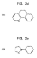
- Fig. 2d is the structural formula of bzq: benzo[h]quinoline
- Fig. 2e is the structural formula of ppz: phenylpyrazole.
- the iridium complexes having such ligands emit phosphorescence from a triplet-state MLCT (Metal To Charge Transfer).
- MLCT Metal To Charge Transfer
- the cationic iridium complex indicated by the chemical formula 1 can emit light of a green region efficiently in a state of the triplet-state MLCT (Metal To Charge Transfer).
- the cationic iridium complex indicated by the chemical formula 1 can emit light of a blue region efficiently in the state of triplet-state MLCT (Metal To Charge Transfer).
- the cationic iridium complex indicated by the chemical formula 1 can emit light of a red region efficiently in the state of triplet-state MLCT (Metal To Charge Transfer).
- the cationic iridium complex indicated by the chemical formula 1 can emit light of a green region efficiently in the state of triplet-state MLCT (Metal To Charge Transfer).
- L cyclometalated ligand
- the cationic iridium complex indicated by the chemical formula 1 can emit light of a green region efficiently in the state of triplet-state MLCT (Metal To Charge Transfer).
- cyclometalated ligand in the general formula 1 is not limited to the above, but any one already known in a field of a light emitting element using a metal complex can be used.
- Fig. 3 is a diagram showing the method for fabricating the iridium complex.
- Fig. 3 is an example in which ppy is added as a ligand for light emission.
- ppyH and IrCl 3 Into a solvent of 2-ethoxyethanol and water are dissolved ppyH and IrCl 3 , and a reaction at 110°C for the thus obtained solution is carried out for 24 hours. Thereby, dimmer-[lr(ppy) 2 Cl] 2 is generated.
- glycerol being a solvent are dissolved dimer-[lr(ppy) 2 Cl] 2 and a hydrophobic ligand L', and a reaction at 180°C for the thus obtained solution is carried out for 6 hours or more.
- X indicates a negative ion such as PF 6 . Since dfppy ppy, and piq are electrically neutral, by providing one dC9bpy or the like, the iridium complex becomes a positive ion.
- Fig. 4a to Fig.4c are structural formulas showing examples of the respective iridium complexes.
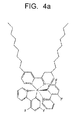
- Fig. 4a is the structural formula of the iridium complex having two dfppy and one dC9bpy as the ligands.
- Fig. 4b is the structural formula of the iridium complex having two bzq and one dC9bpy as the ligands.
- Fig. 4c is the structural formula of the iridium complex having two piq and one dC19bpy as the ligands.
- Fig. 4a to Frig. 4c it is suitable to provide one hydrophobic ligand and two luminescent ligands in one iridium complex.
- a light emitting performance is improved, but if all the ligands are luminescent ligands, the interaction between the cationic iridium complex and the layered silicate results in being small when the cationic iridium complex is intercalated to the layered silicate, so that the effect of the above-described intercalation sometimes results in being insufficient.
- Fig. 5 is a schematic diagram showing an example of a crystal structure of the smectite.
- a composite layer 50 called 2: 1 type which has a structure in which (Si, Al)O 4 tetrahedral sheets 54 sandwich an MO 6 octahedral sheet (M: Mg, Fe, A1 or the like) 56.
- the octahedral sheet 56 has 3 sites which the positive ions enter and bivalent positive ions such as Mg 2+ and Fe 2+ occupy all the three sites, but trivalent positive ions such as Al 3+ occupy only two of three sites.
- the former is classified as three-octahedral type and the latter is classified as two-octahedral type.
- the smectite is a two-octahedral type or three-octahedral type 2: 1 layered silicate, and has a structure in which the composite layer 50 and a water molecule layer 52 are laminated.
- the water molecule layer 52 is constituted by water molecules 58 and an exchangeable positive ion 60 surrounded by the water molecules 58.
- the layered silicate according to the present invention is not limited in particular, and there can be cited, concretely, a smectite represented by a montmorillonite, a beidellite, a nontronite, a saponite, a hectorite, and a stevensite, a mica such as a muscovite, a phlogopite, a taeniolite, a biotite, a margarite, a clintonite, and a four silicon mica, vermiculites such as a two-octahedral type vermiculite and a three-octahedral type vermiculite being altered minerals of mica, a mica clay mineral such as an illite, a sericite, a glauconite, and a celadonite, and so on.
- a smectite represented by a montmorillonite, a beidellite, a
- Such a layered silicate can also be a natural mineral, or can also be a synthetic compound by hydrothermal synthesis, scorification, solid phase synthesis, or the like. Further, in the present invention, one kind of the above-described layered silicates can be used independently, or two or more kinds thereof can be used combinedly. Particularly, a smectite swelling in a water system solvent and a expandable mica are suitable in intercalating a cationic iridium complex.
- an intercalated compound can be easily prepared by carrying out an ion exchange treatment in a positive charge organic compound solution having a comparatively low concentration of a one-fold to five-fold equivalent weight of a cation exchange capacity (CEC).
- a method such as a column infiltration method (see Non-patent Document 5) and a methylene blue adsorption method (see Non-patent Document 6) can be exemplified.
- a non-expandable layered silicate having a potassium ion or the like between layers it is necessary to carry out the ion exchange treatment under a high temperature condition of 60°C or more in a positive charge organic compound solution having a high concentration of a five-fold to twenty-fold equivalent weight of the cation amount between the layers, and adjustment of a reaction condition is necessary depending on the combination of raw materials.
- the cation amount between the layers in such a case is estimated based on an analysis of a chemical composition. Concretely, an inductively coupled plasma (ICP) spectroscopy, an X-ray fluorescence analysis (XRF), an electron probe X-ray microanalyzer (EPMA), or the like is used.
- ICP inductively coupled plasma
- XRF X-ray fluorescence analysis
- EPMA electron probe X-ray microanalyzer
- a method for fabricating an intercalated compound in which a cationic iridium complex is intercalated to a layered silicate will be described.
- a layered silicate such as a smectite is fed into water to have a concentration of 1 to 3 mass% and is stirred. In a case of the smectite, exfoliation occurs and the layered silicate becomes a layered silicate sheet 10 as thin as about 1 nm.
- the cationic iridium complex is dissolved in a water/alcohol mixed solvent, but since the solubility of the cationic iridium complex depends on the molecular structure thereof, the cationic iridium complex can be dissolved by properly changing the proportion of water/alcohol, the kind of alcohol, dissolving temperature, or the like.
- a cationic iridium complex solution is slowly dropped into a suspension of the layered silicate, and is stirred out for several hours. After stirring, filtration is performed and cleaning in a mixed solvent of water/ethanol (1: 1) is carried out. The above is repeated for several times so that an unreacted cationic iridium complex is removed, and thereafter, drying is carried out to prepare an intercalated compound.
- thermoplastic polymer a thermosetting polymer, an energy ray curable polymer, and so on, which are transparent in a desired range of a light wavelength
- thermosetting polymer a thermosetting polymer
- energy ray curable polymer an energy ray curable polymer, and so on, which are transparent in a desired range of a light wavelength
- the suitable polymer can be amorphous or partially crystalline, and can include a homopolymer, a copolymer, or a mixture thereof.
- polystyrene resin such as ionomer resin, poly(carbonate) (PC), syndiotactic or isotactic poly(styrene) (PS), C1 to C8 alkylstyrene, alkyl containing poly(methylmethacrylate) (PMMA) and PMMA copolymer, aromatic series and aliphatic series ring (meth)acrylate, ethoxylated or propoxylated (meth)acrylate, polyfunctional (meth)acrylate, polyether acrylate, epoxy acrylate, urethane
- a term (meth)acrylate is defined as either one of corresponding methacrylate and acrylate compound.
- These polymers can be used in a form of optical isotropy. These can be independent, or can be a polymer alloy of the combination thereof.
- a solvent method of mixing the above polymer and the intercalated compound in a solvent a method of directly mixing the polymer and the intercalated compound, or the like.
- a method of melting and kneading it is possible to use a method of melting and kneading.
- the compound can be made by using a known melting and kneading method such as using a Banbury mixer, a Brabender, a kneader, a roll, a single-axis or multi-axis extruder, and a Ko-kneader.
- a known melting and kneading method such as using a Banbury mixer, a Brabender, a kneader, a roll, a single-axis or multi-axis extruder, and a Ko-kneader.
- the mixing and compounding for the raw materials of the polymer and the intercalated compound can be carried out by a known method such as a stirring reactor, a stirring type homogenizer, an ultrasonic homogenizer, a mortar, a microwave, a three-roll mill, and a bead mill.
- solvents such as water, methanol, ethanol, isopropyl alcohol, butanol, benzyl alcohol, ethylmethylketone, methylisobutylketone, cyclohexanon, ethyl acetoacetate, ⁇ -butyrolactone, butyl acetate, cellosolv series, carbitol, N,N-dimethylformamide, N,N-dimethylacetamide, N,N-dimethylformamide, N-methyl-2-pyrrolidone, dimethylsulfoxide, phenol, a cresol, toluene, xylene, hexamethylbenzene, tetralin, decalin, and dipentene.
- solvents such as water, methanol, ethanol, isopropyl alcohol, butanol, benzyl alcohol, ethylmethylketone, methylisobutylketone, cyclohexanon, ethyl
- the phosphorescence luminescent resin composition of the present invention When the phosphorescence luminescent resin composition of the present invention is to be applied onto a supporting body, it is possible to use an ink state composition prepared by the solvent method or the like. By applying and drying the phosphorescence luminescent resin composition of the present invention on the supporting body as above, a film-shaped molding product, for example, can be obtained.
- the viscosity of the phosphorescence luminescent resin composition containing the solvent is adjusted to be 500 cP to 500,000 cP [measured at 25°C by a Brookfield viscometer].
- the viscosity is more preferably 1,000 cP to 500,000 cP.
- a used amount of the solvent is preferable to be 0.1 to 2 folds by mass of a solid content other than the solvent, in consideration of simplicity in a drying process step. If the used amount exceeds two folds by mass, a solid content concentration becomes low and a sufficient film thickness cannot be obtained by one printing when used as a printing ink, there being a possibility that multiple times of printing are required.
- roller coating, spin coating, screen coating, and curtain coating are possible, and screen printing, ink jet printing, and so on are exemplified.
- the supporting body is not limited in particular, and can be, for example, a polymer film made of polyester resin such as polyethylene terephthalate and aliphatic series polyester or polyolefin resin such as polypropylene and low-density polyethylene, and electrically conductive glass such as glass, ITO, and tin oxide.
- the polymer film is preferable in view of flexibility.
- the molding method is not limited in particular, and any of injection molding, extrusion molding, blow molding, inflation molding, contour extrusion molding, injection blow molding, vacuum pressure molding, fiber forming, electric field fiber forming, and so on can be used suitably.
- the form, the thickness or the like of the molding product of the present invention is not limited in particular, either, and the molding product can be formed in any shape of an injection molded product, an extrusion molded product, a compression molded product, a blow molded product, a sheet shaped product, a film shaped product, a fiber shaped product, a fabric shaped product, and so on.
- a polymer self-standing film can be formed by forming the molding product tin the film shape, or a polymer self-standing film can be formed by coating on a supporting body and then removing the supporting body. Thereby, it is possible to give a polymer self-standing film of 5 to 200 ⁇ m in thickness, for example. It is a matter of course that one thinner or thicker than the above can be fabricated, if necessary.
- ⁇ Ir(bzq) 2 dC9bpy> With glycerol (150g) being a solvent, 0.32 g of dimer-[Ir(bzq) 2 Cl] 2 (FW1246, FURUYA METAL Co., Ltd.) and 0.24 g of 4,4'-dinoryl-2,2' bipyridine dC9bpy (FW409, TOKYO CHEMICAL INDUSTRY CO., LTD.) were dissolved, and stirring at 180°C was carried out for 6 hours while bubbling with N 2 was being performed.
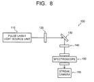
- Fig. 8 is a configuration diagram 100 of the light emission lifetime measurement apparatus used in the present example.
- An arrow indicates light (excitation light or light emission).
- the present example has a configuration constituted by a pulse laser light source unit 110, a light-reducing (neutral density) filter 120, a measurement sample unit 130, a lens 140, a spectroscope 150, and a streak camera 160.
- a sample to be measured is fixed on a quartz glass plate. Then, light emission lifetime measurement in a center wavelength of a light emission spectrum of each sample is carried out. A light emission lifetime ⁇ is calculated from an obtained luminescence decay curve.
- a layered silicate 1.5 g of synthetic saponite (Smecton, KUNIMINE INDUSTRIES CO., LTD.) was added to 200 mL of distilled water, then stirred and dispersed, so that the corresponding suspension was prepared. Further, 0.5 g of the cationic iridium complex [Ir(dfppy) 2 dC9bpy] (ClO 4 ) obtained in the test example 1 was dissolved in water/methanol mixed solvent and thereafter fed into the saponite suspension. Then, the thus obtained solution was stirred and mixed for about 3 hours, and the thus obtained reactant was repeatedly filtered and cleaned. After the drying the reactant, a powdered sample was obtained.
- polymethyl methacrylate PMMA (Mw: 120000, Sigma-Aldrich Co., LLC.) was used and 3 g of PMMA was dissolved into 100 mL of dimethylformamide, and further, 1 phr of [Ir(dfppy) 2 dC9bpy]-Sap in relation to the polymer was added, then stirred and mixed at about 80°C for 3 hours. Thereafter, the thus obtained mixture was fed into a methanol/water mixed solvent, precipitated and dried to obtain a resin composition. The dried resin composition was subjected to thermal press at 260°C and 100 MPa to form a film of 20 ⁇ m. The center wavelength of the light emission spectrum of the film was about 500 nm.
- a sample was prepared completely similarly to in the example 1 except that the cationic iridium complex described in the example 1 was replaced by [Ir(bzq) 2 dC9bpy] (ClO 4 ) obtained in the test example 2.
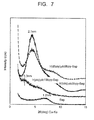
- the bottom face interval of the thus obtained [Ir(bzq) 2 dC9bpy]-Sap was enlarged to 2.1 nm ( Fig. 7 ).
- a luminescent film having a center wavelength of about 550 nm was prepared.
- the polymer and the [Ir(piq) 2 dC19bpy]-Sap were blended at the same compounding ratio as that in the example 1, and with a Labo plastomill (TOYO SEIKI SEISAKU-SHO, LTD.) being equipped with a mixer unit, a melt mixing treatment for the thus obtained blended compound was carried out at 260°C.
- the thus obtained mixture was processed to form a film of 20 ⁇ m in thickness by using thermal pressing.
- a luminescent film having a center wavelength of 600 nm was prepared.
- a sample was prepared completely similarly to in the example 1 except that the synthetic saponite described in the example 1 was replaced by synthetic hectorite HT (SWN, Co-op Chemical Co., Ltd).
- the bottom face interval of [Ir(dfppy) 2 dC9bpy]-HT was enlarged to about 2.0 nm.
- To 100 phr of PMMA was added lphr of [Ir(dfppy) 2 dC9bpy]-HT and a film of 20 ⁇ m in thickness was prepared by a solvent method using dimethylformamide.
- a luminescent film having a center wavelength of about 490 nm was prepared.
- a sample was prepared completely similarly to in the example 2 except that [Ir(bzq) 2 dC9bpy] (ClO 4 ) was used instead of the intercalated compound [Ir(bzq) 2 dC9bpy]-Sap used in the example 2.
- a luminescent film having a center wavelength of about 490 nm was prepared.
- the light emission lifetimes of two components are observed, which are ⁇ 1 : 1.32 ⁇ s and ⁇ 2 : 6.75 ⁇ s, respectively.
Landscapes
- Chemical & Material Sciences (AREA)
- Engineering & Computer Science (AREA)
- Organic Chemistry (AREA)
- Materials Engineering (AREA)
- Medicinal Chemistry (AREA)
- Polymers & Plastics (AREA)
- Manufacturing & Machinery (AREA)
- Health & Medical Sciences (AREA)
- Chemical Kinetics & Catalysis (AREA)
- Wood Science & Technology (AREA)
- Life Sciences & Earth Sciences (AREA)
- Crystallography & Structural Chemistry (AREA)
- Inorganic Chemistry (AREA)
- Physics & Mathematics (AREA)
- Optics & Photonics (AREA)
- Electroluminescent Light Sources (AREA)
- Manufacture Of Macromolecular Shaped Articles (AREA)
- Compositions Of Macromolecular Compounds (AREA)
Abstract
Description
- The present invention relates to a resin composition containing an iridium complex-layered silicate intercalated compound which can be used in an organic light emitting element (OLED) or the like, a film-shaped molding product of the same, and a polymer self-standing film.
- In recent years, in order to enlarge application of an OLED, material development in which a phosphorescence luminescent compound having a high light emission efficiency is being actively carried out. M. A. Baldo et al. obtain an external quantum efficiency of 7.5% by using an iridium complex which emits phosphorescent light from an excited triplet state, which is equivalent to an internal quantum efficiency of 37.5% when an external extraction efficiency is assumed to be 20%, and indicates that it is possible to exceed a value of 25% being an upper limit value of a case where a fluorescent dye is used (Non-patent Document 1).
- An iridium metal complex has characteristics of being extinguished by oxygen, and an example of application of a composite body with a polymer to an oxygen sensor by using such characteristics is disclosed (Non-patent Document 2).
- On the other hand, a layered silicate is a material abundant in a natural world, and is inexpensive. A clay-polymer nanocomposite film, which improves a gas barrier property dramatically while securing transparency of the film itself, is used not only for a food packaging material but also for a fuel tank of an automobile. Application of the clay-polymer nanocomposite film, which exhibits a high gas barrier property, to an oxygen barrier film of a light emitting element or the like can be expected (Non-patent Document 3). Further, it is obvious that a light emission lifetime of an iridium complex absorbed by a clay surface under an oxygen atmosphere is longer than that of a free iridium complex (Non-patent Document 4).
-
- Non-patent Document 1: Applied Physical Letter, 1999, 75, 4.
- Non-patent Document 2: Chemistry of Materials, 2009,21,2173.
- Non-patent Document 3: Chemistry of Materials, 2001, 13, 2217.
- Non-patent Document 4: New Journal of Chemistry, 2010, 34, 617.
- Non-patent Document 5: "Clay Handbook" second edition, by The Clay Science Society of Japan, page 576 to page 577, published by Gihodo
- Non-patent Document 6: Japan Bentonite Manufacturers Association Standard, JBAS-107-91
- Non-patent Document 7: Chem. Mater., 1999, 11, 3342.
- Non-patent Document 8: Transition Met. Chem., 1986, 11, 443. J. Chem. Soc., Dalton Trans. 2001, 2641.
- Non-patent Document 9: Bioorganic & Medical Chem. Lett. 1995. 5, 2989.
- A material having a certain level of flexibility and exhibiting stable emission characteristics is demanded. It is an object of the present invention to provide a light emitting material in which an intercalated compound in which a cationic metal complex is intercalated to a layered silicate is fine-dispersed in a polymer matrix, and a molding product of the same.
- According to an aspect of the present invention, there is given a phosphorescence luminescent resin composition having: an intercalated compound in which a cationic iridium complex indicated by a general formula below is intercalated between layers of a layered silicate; and a polymer in which the intercalated compound is dispersed, wherein the intercalated compound and the polymer are compounded.


- In the formula, R1, R2 each indicate an alkyl group, and L indicates a cyclometalated ligand. As is exemplified below, that cyclometalated ligand emits light as a result that N (nitrogen) and C (carbon) of the cyclometalated ligand is coordinated to Ir in the above-described general formula.
- Here, at least one of R1 and R2 in the cationic iridium complex can have a carbon number of 9 or more.
- Further, L (cyclometalated ligand) in the cationic iridium complex can be indicated by a following formula.

- Further, L (cyclometalated ligand) in the cationic iridium complex can be indicated by a following formula.


- Further, L (cyclometalated ligand) in the cationic iridium complex can be indicated by a following formula.

- Further, L (cyclometalated ligand) in the cationic iridium complex can be indicated by a following formula.

- Further, L (cyclometalated ligand) in the cationic iridium complex can be indicated by a following formula.


- As a result of having L (cyclometalated ligand) indicated by the
chemical formula 2, the cationic iridium complex indicated by the chemical formula 1 can emit light of a green region efficiently in a triplet-state MLCT (Metal To Charge Transfer). Further, as a result of having L (cyclometalated ligand) indicated by the chemical formula 3, the cationic iridium complex indicated by the chemical formula 1 can emit light of a blue region efficiently in the triplet-state MLCT (Metal To Charge Transfer). Further, as a result of having L (cyclometalated ligand) indicated by the chemical formula 4, the cationic iridium complex indicated by the chemical formula 1 can emit light of a red region efficiently in the triplet-state MLCT (Metal To Charge Transfer). - Similarly, as a result of having L (cyclometalated ligand) indicated by the
chemical formula 5, the cationic iridium complex indicated by the chemical formula 1 can emit light of a green region efficiently in a triplet-state MLCT (Metal To Charge Transfer). Further, as a result of having L (cyclometalated ligand) indicated by the chemical formula 6, the cationic iridium complex indicated by the chemical formula 1 can emit light of a green region efficiently in a triplet-state MLCT (Metal To Charge Transfer). - Further, the layered silicate can be a smectite.
- Further, the polymer can be a thermoplastic polymer.
- Further, the polymer can be a thermosetting polymer.
- Further, the polymer can be an energy ray curable polymer.
- Further, a ratio of the intercalated compound in relation to the polymer can be 0.1 to 10 mass%. This is for the reason of enhancing dispersibility of the intercalated compound and stabilizing light emission characteristics and flexibility.
- According to another aspect of the present invention, there is given a film-shaped molding product made by applying and drying any one of the above phosphorescence luminescent resin composition on a supporting body.
- According to still another aspect of the present invention, there is given a polymer self-standing film of 5 to 200µm in thickness constituted by any one of the above phosphorescence luminescent resin compositions.
- According to the present invention, it is possible to provide a material which has stable emission characteristics and flexibility and is excellent in molding workability. Thereby, it is possible to produce a plastic film which is transparent when not excited and emits light by excitation, for example.
-
- [
Fig. 1a] Fig. 1a is a general formula indicating a structure of a hydrophobic ligand and a structural formula indicating an example; - [
Fig. 1b] Fig. 1b is a general formula indicating a structure of a hydrophobic ligand and a structural formula indicating an example; - [
Fig. 1c] Fig. 1c is a general formula indicating a structure of a hydrophobic ligand and a structural formula indicating an example; - [
Fig. 2a] Fig. 2a is a structural formula of a ligand (cyclometalated ligand) for light emission; - [
Fig. 2b] Fig. 2b is a structural formula of a ligand (cyclometalated ligand) for light emission; - [
Fig. 2c] Fig. 2c is a structural formula of a ligand (cyclometalated ligand) for light emission; - [
Fig. 2d ]Fig. 2c is a structural formula of a ligand (cyclometalated ligand) for light emission; - [
Fig. 2e] Fig. 2e is a structural formula of a ligand (cyclometalated ligand) for light emission; - [
Fig. 3] Fig. 3 is a diagram showing a method for fabricating an iridium complex; - [
Fig. 4a] Fig. 4a is a structural formula indicating an example of an iridium complex; - [
Fig. 4b] Fig. 4b is a structural formula indicating an example of an iridium complex; - [
Fig. 4c] Fig. 4c is a structural formula indicating an example of an iridium complex; - [
Fig. 5] Fig. 5 is a schematic diagram showing an example of a crystal structure of a layered silicate represented by a smectite; - [
Fig. 6] Fig. 6 is a graph showing a light emission spectrum of an iridium complex; - [
Fig. 7] Fig. 7 is a measurement result of an X ray diffraction of a saponite (SAP) and a saponite-iridium complex intercalated compound; and - [
Fig. 8] Fig. 8 is a configuration diagram of a light emission lifetime measurement apparatus. - A phosphorescence luminescent resin composition of the present invention has an intercalated compound in which a cationic iridium complex is intercalated between layers of a layered silicate and a polymer as essential constituents.
- The cationic iridium complex will be described. The cationic iridium complex is required to be indicated by a chemical formula 1, and is preferable to be a cationic amphiphile iridium (III) complex.

- In the formula, R1 and R2 each indicate an alkyl group, and L indicates a cyclometalated ligand. As will be exemplified below, the cyclometalated ligand emits light as a result that N (nitrogen) and C (carbon) of the cyclometalated ligand are coordinated to Ir in the above-described general formula. Here, at least one of R1 and R2 in the cationic iridium complex can have a carbon number of 9 or more.
- As a result that a cationic iridium complex has an amphiphile, that cationic iridium complex exhibits both properties of hydrophobic property and hydrophilic property. As a result that the cationic iridium complex exhibits the hydrophobic property, an affinity of the intercalated compound, in which the cationic iridium complex is intercalated, to the polymer of is increased. Thereby, it is possible to make the bond between the intercalated compound and the polymer stronger. Further, as a result that the cationic iridium complex exhibits the hydrophilic property, an interaction (ion-exchange) with the layered silicate is improved, and an interaction of the cationic iridium complex with the layered silicate is increased. Therefore, it is possible to obtain an effect of the aforementioned intercalation sufficiently.
- The cationic amphiphile iridium (III) complex has three ligands in an iridium metal.
Fig. 1a is a general formula indicating a structure of a hydrophobic ligand, andFig. 1b and Fig. 1c are structural formulas showing examples relating to the hydrophobic ligand. Both R1 and R2 shown inFig. 1a are alkyl groups, and at least one thereof has 9 or more carbons. By using bpy fulfilling such a condition, the hydrophobic ligand is given. R1 and R2 can be the same, or can be different. -
Fig. 1b is the structural formula of dC9bpy (4,4'-dinonyl-2,2'-bipyridine), andFig. 1c is the structural formula of dC19bpy (4,4'-dinonadecyl-2,2'-bipyridine). -
Fig. 2a to Fig. 2e are structural formulas of ligands for light emission, that is, of the cyclometalated ligands (L).Fig. 2a is the structural formula of ppy: 2-phenylpyridine,Fig. 2b is the structural formula of dfppy: 2-(2',4'-difluorophenyl)pyridine,Fig. 2c is the structural formula of piq: 1-phenyisoquinoline,Fig. 2d is the structural formula of bzq: benzo[h]quinoline, andFig. 2e is the structural formula of ppz: phenylpyrazole. The iridium complexes having such ligands emit phosphorescence from a triplet-state MLCT (Metal To Charge Transfer). - As a result of having the cyclometalated ligand (L) shown in
Fig. 2a , the cationic iridium complex indicated by the chemical formula 1 can emit light of a green region efficiently in a state of the triplet-state MLCT (Metal To Charge Transfer). Further, as a result of having the cyclometalated ligand (L) shown inFig. 2b , the cationic iridium complex indicated by the chemical formula 1 can emit light of a blue region efficiently in the state of triplet-state MLCT (Metal To Charge Transfer). Further, as a result of having the cyclometalated ligand (L) shown inFig. 2c , the cationic iridium complex indicated by the chemical formula 1 can emit light of a red region efficiently in the state of triplet-state MLCT (Metal To Charge Transfer). - Similarly, as a result of having the cyclometalated ligand (L) shown in
Fig. 2d , the cationic iridium complex indicated by the chemical formula 1 can emit light of a green region efficiently in the state of triplet-state MLCT (Metal To Charge Transfer). Further, as a result of having L (cyclometalated ligand) shown inFig. 2e , the cationic iridium complex indicated by the chemical formula 1 can emit light of a green region efficiently in the state of triplet-state MLCT (Metal To Charge Transfer). - Note that the cyclometalated ligand in the general formula 1 is not limited to the above, but any one already known in a field of a light emitting element using a metal complex can be used.
- A method for fabricating an iridium complex will be described.
Fig. 3 is a diagram showing the method for fabricating the iridium complex.Fig. 3 is an example in which ppy is added as a ligand for light emission. Into a solvent of 2-ethoxyethanol and water are dissolved ppyH and IrCl3, and a reaction at 110°C for the thus obtained solution is carried out for 24 hours. Thereby, dimmer-[lr(ppy)2Cl]2 is generated. Further, into with glycerol being a solvent are dissolved dimer-[lr(ppy)2Cl]2 and a hydrophobic ligand L', and a reaction at 180°C for the thus obtained solution is carried out for 6 hours or more. Thereby, [lr(ppy)2L']X is generated. Here, X indicates a negative ion such as PF6. Since dfppy ppy, and piq are electrically neutral, by providing one dC9bpy or the like, the iridium complex becomes a positive ion. -
Fig. 4a to Fig.4c are structural formulas showing examples of the respective iridium complexes.Fig. 4a is the structural formula of the iridium complex having two dfppy and one dC9bpy as the ligands.Fig. 4b is the structural formula of the iridium complex having two bzq and one dC9bpy as the ligands.Fig. 4c is the structural formula of the iridium complex having two piq and one dC19bpy as the ligands. - In
Fig. 4a to Frig. 4c, it is suitable to provide one hydrophobic ligand and two luminescent ligands in one iridium complex. As the number of the luminescent ligands increases, a light emitting performance is improved, but if all the ligands are luminescent ligands, the interaction between the cationic iridium complex and the layered silicate results in being small when the cationic iridium complex is intercalated to the layered silicate, so that the effect of the above-described intercalation sometimes results in being insufficient. - Next, the layered silicate will be described by using a smectite as an example.
Fig. 5 is a schematic diagram showing an example of a crystal structure of the smectite. There is formed acomposite layer 50 called 2: 1 type which has a structure in which (Si, Al)O4tetrahedral sheets 54 sandwich an MO6 octahedral sheet (M: Mg, Fe, A1 or the like) 56. Theoctahedral sheet 56 has 3 sites which the positive ions enter and bivalent positive ions such as Mg2+ and Fe2+ occupy all the three sites, but trivalent positive ions such as Al3+ occupy only two of three sites. The former is classified as three-octahedral type and the latter is classified as two-octahedral type. The smectite is a two-octahedral type or three-octahedral type 2: 1 layered silicate, and has a structure in which thecomposite layer 50 and awater molecule layer 52 are laminated. Thewater molecule layer 52 is constituted bywater molecules 58 and an exchangeablepositive ion 60 surrounded by thewater molecules 58. - The layered silicate according to the present invention is not limited in particular, and there can be cited, concretely, a smectite represented by a montmorillonite, a beidellite, a nontronite, a saponite, a hectorite, and a stevensite, a mica such as a muscovite, a phlogopite, a taeniolite, a biotite, a margarite, a clintonite, and a four silicon mica, vermiculites such as a two-octahedral type vermiculite and a three-octahedral type vermiculite being altered minerals of mica, a mica clay mineral such as an illite, a sericite, a glauconite, and a celadonite, and so on. Such a layered silicate can also be a natural mineral, or can also be a synthetic compound by hydrothermal synthesis, scorification, solid phase synthesis, or the like. Further, in the present invention, one kind of the above-described layered silicates can be used independently, or two or more kinds thereof can be used combinedly. Particularly, a smectite swelling in a water system solvent and a expandable mica are suitable in intercalating a cationic iridium complex.
- In a case of an easily ion exchangeable or expandable layered silicate such as a smectite or a expandable mica, an intercalated compound can be easily prepared by carrying out an ion exchange treatment in a positive charge organic compound solution having a comparatively low concentration of a one-fold to five-fold equivalent weight of a cation exchange capacity (CEC). As a measuring method of the CEC, a method such as a column infiltration method (see Non-patent Document 5) and a methylene blue adsorption method (see Non-patent Document 6) can be exemplified. However, in a case of a non-expandable layered silicate having a potassium ion or the like between layers, it is necessary to carry out the ion exchange treatment under a high temperature condition of 60°C or more in a positive charge organic compound solution having a high concentration of a five-fold to twenty-fold equivalent weight of the cation amount between the layers, and adjustment of a reaction condition is necessary depending on the combination of raw materials. The cation amount between the layers in such a case is estimated based on an analysis of a chemical composition. Concretely, an inductively coupled plasma (ICP) spectroscopy, an X-ray fluorescence analysis (XRF), an electron probe X-ray microanalyzer (EPMA), or the like is used.
- A method for fabricating an intercalated compound in which a cationic iridium complex is intercalated to a layered silicate will be described. A layered silicate such as a smectite is fed into water to have a concentration of 1 to 3 mass% and is stirred. In a case of the smectite, exfoliation occurs and the layered silicate becomes a
layered silicate sheet 10 as thin as about 1 nm. The cationic iridium complex is dissolved in a water/alcohol mixed solvent, but since the solubility of the cationic iridium complex depends on the molecular structure thereof, the cationic iridium complex can be dissolved by properly changing the proportion of water/alcohol, the kind of alcohol, dissolving temperature, or the like. A cationic iridium complex solution is slowly dropped into a suspension of the layered silicate, and is stirred out for several hours. After stirring, filtration is performed and cleaning in a mixed solvent of water/ethanol (1: 1) is carried out. The above is repeated for several times so that an unreacted cationic iridium complex is removed, and thereafter, drying is carried out to prepare an intercalated compound. - As a polymer constituting the phosphorescence luminescent resin composition of the present invention, there can be cited a thermoplastic polymer, a thermosetting polymer, an energy ray curable polymer, and so on, which are transparent in a desired range of a light wavelength, but any polymer can be used and there is no limitation in particular. The suitable polymer can be amorphous or partially crystalline, and can include a homopolymer, a copolymer, or a mixture thereof.
- As examples of the polymer, there can be cited high-density polyethylene (HDPE), low-density polyethylene (LDPE), linear low-density polyethylene (LLDPE), polypropylene (PP), ethylene-propylene copolymer, ethylene-butene copolymer, ethylene-hexene copolymer, ethylene vinyl acetate copolymer, ethylene methacrylate copolymer, polyolefin resin such as ionomer resin, poly(carbonate) (PC), syndiotactic or isotactic poly(styrene) (PS), C1 to C8 alkylstyrene, alkyl containing poly(methylmethacrylate) (PMMA) and PMMA copolymer, aromatic series and aliphatic series ring (meth)acrylate, ethoxylated or propoxylated (meth)acrylate, polyfunctional (meth)acrylate, polyether acrylate, epoxy acrylate, urethane acrylate, polybutadiene acrylate, silicone acrylate, melamine acrylate, acrylated epoxy, phenol resin, silicone resin, epoxy resin and other ethylenically unsaturated materials, cyclic olefin and cyclic olefin copolymer, polyvinyl carbazole, acrylonitrile butadiene styrene (ABS), styrene-acrylonitrile copolymer (SAN), poly(vinylcyclohexane), PMMA/poly(vinyl fluoride) blend, styrene-based block copolymer, polyimide, halogen containing resin such as polysulfone, polyvinyl chloride, polyvinylidene chloride and polyvinylidene fluoride, poly(dimethylsiloxane) (PDMS), polyurethane, saturated polyester, poly(alkane terephthalate) such as, for example, poly(ethylene terephthalate) (PET), poly(alkane naphthalate) such as, for example, poly(ethylene naphthalate) (PEN), polyamide resin such as polyamide 6, polyamide 66, polyamide 11, polyamide 12, aromatic series polyamide, and polymethacrylimide, and copolymer thereof, ionomer, vinyl acetate/ polyethylene copolymer, cellulose acetate, cellulose acetate butyrate, fluoropolymer, poly(styrene)-poly(ethylene) copolymer, polyolefin based PET and PET containing PEN and PEN copolymer, and poly(carbonate)/aliphatic PET blend, but the polymer is not limited to the above.
- Note that a term (meth)acrylate is defined as either one of corresponding methacrylate and acrylate compound. These polymers can be used in a form of optical isotropy. These can be independent, or can be a polymer alloy of the combination thereof.
- As a method for compounding the aforementioned polymer and the intercalated compound made of the cationic iridium complex and the layered silicate, there is used a solvent method of mixing the above polymer and the intercalated compound in a solvent, a method of directly mixing the polymer and the intercalated compound, or the like. In a case of the polymer which is solid at a room temperature, it is possible to use a method of melting and kneading. For example, the compound can be made by using a known melting and kneading method such as using a Banbury mixer, a Brabender, a kneader, a roll, a single-axis or multi-axis extruder, and a Ko-kneader.
- In a case of the solvent method, the mixing and compounding for the raw materials of the polymer and the intercalated compound can be carried out by a known method such as a stirring reactor, a stirring type homogenizer, an ultrasonic homogenizer, a mortar, a microwave, a three-roll mill, and a bead mill. As concrete examples of the solvent to be used, the solvent being not limited in particular as long as the polymer is dissolved, there can be cited solvents such as water, methanol, ethanol, isopropyl alcohol, butanol, benzyl alcohol, ethylmethylketone, methylisobutylketone, cyclohexanon, ethyl acetoacetate, γ-butyrolactone, butyl acetate, cellosolv series, carbitol, N,N-dimethylformamide, N,N-dimethylacetamide, N,N-dimethylformamide, N-methyl-2-pyrrolidone, dimethylsulfoxide, phenol, a cresol, toluene, xylene, hexamethylbenzene, tetralin, decalin, and dipentene. The above can be used independently, and can be used as a mixture of a combination of two kinds or more thereof.
- When the phosphorescence luminescent resin composition of the present invention is to be applied onto a supporting body, it is possible to use an ink state composition prepared by the solvent method or the like. By applying and drying the phosphorescence luminescent resin composition of the present invention on the supporting body as above, a film-shaped molding product, for example, can be obtained.
- It is preferable that the viscosity of the phosphorescence luminescent resin composition containing the solvent is adjusted to be 500 cP to 500,000 cP [measured at 25°C by a Brookfield viscometer]. The viscosity is more preferably 1,000 cP to 500,000 cP. A used amount of the solvent is preferable to be 0.1 to 2 folds by mass of a solid content other than the solvent, in consideration of simplicity in a drying process step. If the used amount exceeds two folds by mass, a solid content concentration becomes low and a sufficient film thickness cannot be obtained by one printing when used as a printing ink, there being a possibility that multiple times of printing are required.
- As a concrete usage, roller coating, spin coating, screen coating, and curtain coating are possible, and screen printing, ink jet printing, and so on are exemplified.
- The supporting body is not limited in particular, and can be, for example, a polymer film made of polyester resin such as polyethylene terephthalate and aliphatic series polyester or polyolefin resin such as polypropylene and low-density polyethylene, and electrically conductive glass such as glass, ITO, and tin oxide. The polymer film is preferable in view of flexibility.
- Further, in manufacturing a molding product from a material compounded by a method such as melt-mixing, the molding method is not limited in particular, and any of injection molding, extrusion molding, blow molding, inflation molding, contour extrusion molding, injection blow molding, vacuum pressure molding, fiber forming, electric field fiber forming, and so on can be used suitably. The form, the thickness or the like of the molding product of the present invention is not limited in particular, either, and the molding product can be formed in any shape of an injection molded product, an extrusion molded product, a compression molded product, a blow molded product, a sheet shaped product, a film shaped product, a fiber shaped product, a fabric shaped product, and so on. For example, a polymer self-standing film can be formed by forming the molding product tin the film shape, or a polymer self-standing film can be formed by coating on a supporting body and then removing the supporting body. Thereby, it is possible to give a polymer self-standing film of 5 to 200 µm in thickness, for example. It is a matter of course that one thinner or thicker than the above can be fabricated, if necessary.
- Hereinafter, the present invention will be described in more detail by examples.
- As a cationic iridium complex, there are synthesized <Ir(dfppy)2dC9bpy>, <Ir(piq)2dC19bpy>, and <Ir(bzq)2dC19bpy> below.
- <Ir(dfppy)2dC9bpy>: With glycerol (150g) being a solvent, 0.32 g of dimer-[Ir(dfppy)2Cl]2 (FW1246, FURUYA METAL Co., Ltd.) and 0.24 g of 4,4'-dinoryl-2,2' bipyridine dC9bpy (FW409, TOKYO CHEMICAL INDUSTRY CO., LTD.) were dissolved, and stirring at 180°C was carried out for 6 hours while bubbling with N2 was being performed. After the reaction was finished, water and sodium perchlorate were added. Then, the thus obtained reactant was separated and the thus obtained high-purity component was extracted by chloroform. As a result, the sample of [Ir(dfppy)2dC9bpy] (ClO4) was obtained. The light emission spectrum of the sample was measured by a fluorescence spectrophotometer (FP-6500, JASCO Corporation). The obtained light emission spectrum is shown in a graph a in
Fig. 6 . A peak wavelength is about 500 nm. - <Ir(bzq)2dC9bpy>: With glycerol (150g) being a solvent, 0.32 g of dimer-[Ir(bzq)2Cl]2 (FW1246, FURUYA METAL Co., Ltd.) and 0.24 g of 4,4'-dinoryl-2,2' bipyridine dC9bpy (FW409, TOKYO CHEMICAL INDUSTRY CO., LTD.) were dissolved, and stirring at 180°C was carried out for 6 hours while bubbling with N2 was being performed. After the reaction was finished, water and sodium perchlorate were added, and thereafter, the thus obtained high-purity component was extracted by chloroform, and the sample of [Ir(bzq)2dC9bpy] (ClO4) was obtained. A light emission spectrum of the obtained sample is shown in a graph b in
Fig. 6 . A peak wavelength is about 560 nm. - <Ir(piq)2dC19bpy>: According to Non-patent Documents 7 to 9, 4,4'- dinonadecyl-2,2' bipyridine(dC19bpy) was prepared. With glycerol (130g) being a solvent, 0.326 g of dimer-[Ir(piq)2Cl]2 (FW1271, FURUYA METAL Co., Ltd.) and 0.39 g of dC19bpy (FW689) were dissolved, and stirring at 180°C was carried out for 6 hours while bubbling with N2 was being performed. After the reaction was finished, water and sodium perchlorate were added. Then, the thus obtained reactant was separated and the thus obtained high-purity component was extracted by chloroform. As a result the sample of [Ir(piq)2dC19bpy] (ClO4) was obtained. A light emission spectrum of the obtained sample is shown in a graph c in
Fig. 6 . A peak wavelength is about 600 nm. - First, a light emission lifetime measurement apparatus used in the present example will be described.
Fig. 8 is a configuration diagram 100 of the light emission lifetime measurement apparatus used in the present example. An arrow indicates light (excitation light or light emission). - In
Fig. 8 , the present example has a configuration constituted by a pulse laserlight source unit 110, a light-reducing (neutral density)filter 120, ameasurement sample unit 130, alens 140, aspectroscope 150, and astreak camera 160. A sample to be measured is fixed on a quartz glass plate. Then, light emission lifetime measurement in a center wavelength of a light emission spectrum of each sample is carried out. A light emission lifetime τ is calculated from an obtained luminescence decay curve. - As a layered silicate, 1.5 g of synthetic saponite (Smecton, KUNIMINE INDUSTRIES CO., LTD.) was added to 200 mL of distilled water, then stirred and dispersed, so that the corresponding suspension was prepared. Further, 0.5 g of the cationic iridium complex [Ir(dfppy)2dC9bpy] (ClO4) obtained in the test example 1 was dissolved in water/methanol mixed solvent and thereafter fed into the saponite suspension. Then, the thus obtained solution was stirred and mixed for about 3 hours, and the thus obtained reactant was repeatedly filtered and cleaned. After the drying the reactant, a powdered sample was obtained. For evaluation of the obtained sample, change of bottom face reflection of the layered silicate was investigated by an X-ray diffraction instrument (Cu-Kα radiation). While the bottom face interval of untreated saponite was 1.2 nm, the bottom face interval of the sample after reaction was about 2.0 nm (
Fig. 7 ). In other words, [Ir(dfppy)2dC9bpy]-Sap in which the corresponding Ir(dfppy)2dC9bpy molecule was intercalated between clay layers was prepared. - As the polymer, polymethyl methacrylate PMMA (Mw: 120000, Sigma-Aldrich Co., LLC.) was used and 3 g of PMMA was dissolved into 100 mL of dimethylformamide, and further, 1 phr of [Ir(dfppy)2dC9bpy]-Sap in relation to the polymer was added, then stirred and mixed at about 80°C for 3 hours. Thereafter, the thus obtained mixture was fed into a methanol/water mixed solvent, precipitated and dried to obtain a resin composition. The dried resin composition was subjected to thermal press at 260°C and 100 MPa to form a film of 20 µm. The center wavelength of the light emission spectrum of the film was about 500 nm. As a result of light emission lifetime measurement (Table 1), the light emission lifetimes of two components are observed, which are τ1: 1.48 µs and τ2: 4.82 µs, respectively, which shows that the component having the longer light emission lifetimes is detected in comparison with the [Ir(dfppy)2dC9bpy] (ClO4) and the [Ir(dfppy)2dC9bpy]-Sap as the raw materials.
- A sample was prepared completely similarly to in the example 1 except that the cationic iridium complex described in the example 1 was replaced by [Ir(bzq)2dC9bpy] (ClO4) obtained in the test example 2. The bottom face interval of the thus obtained [Ir(bzq)2dC9bpy]-Sap was enlarged to 2.1 nm (
Fig. 7 ). As the light emission spectrum investigation, a luminescent film having a center wavelength of about 550 nm was prepared. As a result of the light emission lifetime measurement (Table 1), the light emission lifetimes of two components are observed, which are τ1: 1.54 µs and τ2: 10.65 µs, respectively, which shows that the component having the longer light emission lifetimes is detected in comparison with the [Ir(bzq)2dC9bpy] (ClO4) and the [Ir(bzq)2dC9bpy]-Sap as the raw materials. - With the cationic iridium complex described in the example 1 being replaced by[Ir(piq)2dC19bpy] (ClO4) obtained in the test example 3, [Ir(piq)2dC19bpy]-Sap was prepared by a procedure of the example 1. A result of X-ray diffraction measurement indicates that the bottom face interval was enlarged to about 3.3 nm (
Fig. 7 ). The polymer and the [Ir(piq)2dC19bpy]-Sap were blended at the same compounding ratio as that in the example 1, and with a Labo plastomill (TOYO SEIKI SEISAKU-SHO, LTD.) being equipped with a mixer unit, a melt mixing treatment for the thus obtained blended compound was carried out at 260°C. The thus obtained mixture was processed to form a film of 20 µm in thickness by using thermal pressing. As a result of the light emission spectrum investigation, a luminescent film having a center wavelength of 600 nm was prepared. As a result of the light emission lifetime measurement (Table 1), light emission lifetimes of two components were observed, which are τ1: 2.61 µs and τ2: 6.17 µs, respectively, which shows that the component having the longer light emission lifetimes is detected in comparison with the [Ir(bzq)2dC9bpy] (ClO4) and the [Ir(bzq)2dC9bpy]-Sap as the raw materials.TABLE. 1 τ 1[µs] τ 2[µs] EXAMPLE 1 1.48 4.82 EXAMPLE 2 1.54 10.65 EXAMPLE 3 2.61 6.17 EXAMPLE 4 1.36 5.37 COMPARATIVE EXAMPLE 1 1.32 6.75 COMPARATIVE EXAMPLE 2 2.54 5.63 [Ir(dfppy)2(dC9bpy)](ClO4) 0.61 2.49 [Ir(bzq)2(dC9bpy)](ClO4) 0.20 0.59 [Ir(piq)2(dC19bpy)](ClO4) 0.50 0.58 [Ir(dfppy)2(dC9bpy)]-Sap 0.33 0.67 [Ir(bzq)2(dC9bpy)]-Sap 0.60 1.18 [Ir(piq)2(dC19bpy)]-Sap 0.78 3.68 - A sample was prepared completely similarly to in the example 1 except that the synthetic saponite described in the example 1 was replaced by synthetic hectorite HT (SWN, Co-op Chemical Co., Ltd). The bottom face interval of [Ir(dfppy)2dC9bpy]-HT was enlarged to about 2.0 nm. To 100 phr of PMMA was added lphr of [Ir(dfppy)2dC9bpy]-HT and a film of 20 µm in thickness was prepared by a solvent method using dimethylformamide. As the light emission spectrum investigation, a luminescent film having a center wavelength of about 490 nm was prepared. As a result of the light emission lifetime measurement (Table 1), the light emission lifetimes of two components are observed, which are τ1: 1.36 µs and τ2: 5.37 µs, respectively, which shows that the component having the longer light emission lifetimes is detected in comparison with the [Ir(bzq)2dC9bpy] (ClO4).
- A sample was prepared completely similarly to in the example 2 except that [Ir(bzq)2dC9bpy] (ClO4) was used instead of the intercalated compound [Ir(bzq)2dC9bpy]-Sap used in the example 2. As the light emission spectrum investigation, a luminescent film having a center wavelength of about 490 nm was prepared. As a result of the light emission lifetime measurement (Table 1), the light emission lifetimes of two components are observed, which are τ1: 1.32 µs and τ2: 6.75 µs, respectively.
- A sample was prepared completely similarly to in the example3 except that [Ir(piq)2dC19bpy] (ClO4) was used instead of the intercalated compound [Ir(piq)2dC19bpy]-Sap used in the example 3. As the light emission spectrum investigation, a luminescent film having a center wavelength of about 490 nm was prepared. As a result of the light emission lifetime measurement (Table 1), the light emission lifetimes of two components are observed, which are τ1: 2.54 µs and τ2: 5.63 µs, respectively.
- Hereinabove, preferred examples of the invention are described in detail, but the present invention is not limited to the specific examples and can be changed or modified in various ways in a scope of the gist of the present invention described in what is claimed.
Claims (14)
- A phosphorescence luminescent resin composition comprising:an intercalated compound in which a cationic iridium complex indicated by a general formula below is intercalated between layers of a layered silicate; anda polymer in which said intercalated compound is dispersed,wherein said intercalated compound and said polymer are compounded. [Chemical Formula 1]
 (In the formula, R1, R2 each indicates an alkyl group, and L indicates a cyclometalated ligand.)
 - The phosphorescence luminescent composition according to claim 1, wherein at least one of R1 and R2 in the cationic iridium complex has a carbon number of 9 or more.
- The phosphorescence luminescent resin composition according to claim 1 or 2,
wherein L in the cationic iridium complex is indicated by a following formula.
- The phosphorescence luminescent resin composition according to claim 1 or 2, wherein L in the cationic iridium complex is indicated by a following formula.


- The phosphorescence luminescent resin composition according to claim 1 or 2, wherein L in the cationic iridium complex is indicated by a following formula.

- The phosphorescence luminescent resin composition according to claim 1 or 2, wherein L in the cationic iridium complex is indicated by a following formula.

- The phosphorescence luminescent resin composition according to claim 1 or 2, wherein L in the cationic iridium complex is indicated by a following formula.


- The phosphorescence luminescent resin composition according to any one of claims 1 to 6,
wherein the layered silicate is smectite. - The phosphorescence luminescent resin composition according to any one of claims 1 to 7,
wherein said polymer is a thermoplastic polymer. - The phosphorescence luminescent resin composition according to any one of claims 1 to 7,
wherein said polymer is a thermosetting polymer. - The phosphorescence luminescent resin composition according to any one of claims 1 to 7,
wherein said polymer is an energy ray curable polymer. - The phosphorescence luminescent resin composition according to any one of claims 1 to 10,
wherein a ratio of said intercalated compound in relation to said polymer is 0.1 to 10 mass%. - A film-shaped molding product made by applying and drying the phosphorescence luminescent resin composition according to any one of claims 1 to 12 on a supporting body.
- A polymer self-standing film of 5 to 200 µm in thickness made of the phosphorescence luminescent resin composition according to any one of claims 1 to 12.
Applications Claiming Priority (2)
| Application Number | Priority Date | Filing Date | Title |
|---|---|---|---|
| JP2011273797A JP5817497B2 (en) | 2011-12-14 | 2011-12-14 | Luminescent resin composition, film-like molded body thereof, and polymer self-supporting film |
| PCT/JP2012/007960 WO2013088720A1 (en) | 2011-12-14 | 2012-12-13 | Luminescent resin composition, film-shaped molding of same, and polymer free-standing film |
Publications (3)
| Publication Number | Publication Date |
|---|---|
| EP2792718A1 true EP2792718A1 (en) | 2014-10-22 |
| EP2792718A4 EP2792718A4 (en) | 2015-08-26 |
| EP2792718B1 EP2792718B1 (en) | 2017-02-08 |
Family
ID=48612193
Family Applications (1)
| Application Number | Title | Priority Date | Filing Date |
|---|---|---|---|
| EP12856825.0A Not-in-force EP2792718B1 (en) | 2011-12-14 | 2012-12-13 | Luminescent resin composition, film-shaped molding of same, and polymer self-standing film |
Country Status (4)
| Country | Link |
|---|---|
| US (1) | US20140335340A1 (en) |
| EP (1) | EP2792718B1 (en) |
| JP (1) | JP5817497B2 (en) |
| WO (1) | WO2013088720A1 (en) |
Families Citing this family (3)
| Publication number | Priority date | Publication date | Assignee | Title |
|---|---|---|---|---|
| JP6621291B2 (en) * | 2015-10-05 | 2019-12-18 | 国立研究開発法人物質・材料研究機構 | Method for producing water-swellable layered silicate |
| JP2019183045A (en) * | 2018-04-13 | 2019-10-24 | 公立大学法人首都大学東京 | Light emission adjustment method of luminescent composition and sensor using the same |
| CN109467983B (en) * | 2018-12-14 | 2021-02-05 | 中国科学院长春应用化学研究所 | Organic small-molecule luminescent material ink and preparation method thereof |
Family Cites Families (11)
| Publication number | Priority date | Publication date | Assignee | Title |
|---|---|---|---|---|
| JPH02103033A (en) * | 1988-10-12 | 1990-04-16 | Shimadzu Corp | location recording material |
| JP2900447B2 (en) * | 1989-11-21 | 1999-06-02 | 株式会社島津製作所 | Hologram recording material |
| US6828370B2 (en) * | 2000-05-30 | 2004-12-07 | Amcol International Corporation | Intercalates and exfoliates thereof having an improved level of extractable material |
| JP2004107541A (en) * | 2002-09-19 | 2004-04-08 | Fuji Photo Film Co Ltd | POLYMER COMPOSITION, FILM, GAS BARRIER FILM CONTAINING ORGANIC MODIFIED LAYER SILATE, AND SUBSTRATE AND IMAGE DISPLAY DEVICE USING THEM |
| JP2005128140A (en) * | 2003-10-22 | 2005-05-19 | Dainippon Ink & Chem Inc | Optical sheet and backlight unit using the same |
| JP2006265383A (en) * | 2005-03-24 | 2006-10-05 | Fuji Photo Film Co Ltd | Resin composition, film using the same, and image display device |
| JP2007311615A (en) * | 2006-05-19 | 2007-11-29 | Asahi Kasei Corp | Organic electroluminescence device |
| JP5253063B2 (en) * | 2008-09-17 | 2013-07-31 | 協立化学産業株式会社 | Sealant composition for liquid crystal display device |
| WO2010037667A1 (en) * | 2008-10-02 | 2010-04-08 | Basf Se | Complex salts |
| US8372977B2 (en) * | 2009-07-14 | 2013-02-12 | The University Of Hong Kong | Luminescent gold(III) compounds containing bidentate ligand for organic light-emitting devices and their preparation |
| JP5681036B2 (en) * | 2011-04-25 | 2015-03-04 | 国立大学法人愛媛大学 | Hybrid membrane and gas sensor |
-
2011
- 2011-12-14 JP JP2011273797A patent/JP5817497B2/en not_active Expired - Fee Related
-
2012
- 2012-12-13 US US14/363,904 patent/US20140335340A1/en not_active Abandoned
- 2012-12-13 EP EP12856825.0A patent/EP2792718B1/en not_active Not-in-force
- 2012-12-13 WO PCT/JP2012/007960 patent/WO2013088720A1/en not_active Ceased
Also Published As
| Publication number | Publication date |
|---|---|
| US20140335340A1 (en) | 2014-11-13 |
| JP2013124303A (en) | 2013-06-24 |
| EP2792718B1 (en) | 2017-02-08 |
| JP5817497B2 (en) | 2015-11-18 |
| WO2013088720A1 (en) | 2013-06-20 |
| EP2792718A4 (en) | 2015-08-26 |
Similar Documents
| Publication | Publication Date | Title |
|---|---|---|
| Hu et al. | Stable and bright pyridine manganese halides for efficient white light‐emitting diodes | |
| Tai et al. | Ultrastable, deformable, and stretchable luminescent organic–inorganic perovskite nanocrystal–polymer composites for 3D printing and white light-emitting diodes | |
| DE112013002566B4 (en) | Light-emitting element, light-emitting device, display device, electronic device and lighting device | |
| EP2595997B1 (en) | Copper(i) complexes for optoelectronic devices | |
| WO2010031485A1 (en) | Materials for organic electroluminescence devices | |
| JP6744217B2 (en) | Luminescent hybrid nanomaterials for aggregation-induced luminescence | |
| EP2792718B1 (en) | Luminescent resin composition, film-shaped molding of same, and polymer self-standing film | |
| WO2011032626A1 (en) | Metal complexes | |
| TWI761353B (en) | Composition and compound | |
| WO2015039723A1 (en) | Polycyclic phenylpyridine iridium complexes and derivatives thereof for oleds | |
| Fresta et al. | Deciphering the Electroluminescence Behavior of Silver (I)‐Complexes in Light‐Emitting Electrochemical Cells: Limitations and Solutions toward Highly Stable Devices | |
| KR20200062664A (en) | Perovskite Quantum dot nanocomposite ink capable of inkjet patterning | |
| JP2018002712A (en) | Compound, dispersion composition, resin composition, film, laminate structure and light-emitting device | |
| KR20140015306A (en) | Phosphorescent material, process for producing phosphorescent material, and phosphorescent element | |
| Solodov et al. | High-throughput, low-cost and “green” production method for highly stable polypropylene/perovskite composites, applicable in 3D printing | |
| Xing et al. | Dye encapsulation engineering in a tetraphenylethylene-based MOF for tunable white-light emission | |
| Somjit et al. | Encapsulation of aggregation-caused quenching dye in metal-organic framework as emissive layer of organic light-emitting diodes | |
| Liang et al. | An AIE-active acridine functionalized spiro [fluorene-9, 9′-xanthene] luminophore with mechanoresponsive luminescence for anti-counterfeiting, information encryption and blue OLEDs | |
| Yoshida et al. | Effects of the surface charge density of clay minerals on surface-fixation induced emission of acridinium derivatives | |
| Li et al. | Low toxicity antisolvent synthesis of composition-tunable luminescent all-inorganic perovskite nanocrystals | |
| JP6902539B2 (en) | Compounds, dispersion compositions and resin compositions | |
| EP3037853A1 (en) | Colour filter, colour filter array and organic light-emitting display device using the same | |
| Takahira et al. | Design, synthesis, and properties of a series of charged iridium (III) complexes with a neutral bidentate ligand for deep-blue phosphorescent emitter | |
| Yoo et al. | Drying stability enhancement of red-perovskite colloidal ink via ligand-derived coating for inkjet printing | |
| DE102013200085B4 (en) | Highly efficient phosphorescent materials |
Legal Events
| Date | Code | Title | Description |
|---|---|---|---|
| PUAI | Public reference made under article 153(3) epc to a published international application that has entered the european phase |
Free format text: ORIGINAL CODE: 0009012 |
|
| 17P | Request for examination filed |
Effective date: 20140610 |
|
| AK | Designated contracting states |
Kind code of ref document: A1 Designated state(s): AL AT BE BG CH CY CZ DE DK EE ES FI FR GB GR HR HU IE IS IT LI LT LU LV MC MK MT NL NO PL PT RO RS SE SI SK SM TR |
|
| DAX | Request for extension of the european patent (deleted) | ||
| RA4 | Supplementary search report drawn up and despatched (corrected) |
Effective date: 20150729 |
|
| RIC1 | Information provided on ipc code assigned before grant |
Ipc: C08K 9/04 20060101ALI20150721BHEP Ipc: C08L 101/00 20060101AFI20150721BHEP Ipc: C08K 5/3445 20060101ALI20150721BHEP Ipc: C08J 7/04 20060101ALI20150721BHEP Ipc: H05B 33/14 20060101ALI20150721BHEP Ipc: C08K 5/00 20060101ALI20150721BHEP Ipc: C08K 5/3432 20060101ALI20150721BHEP Ipc: H01L 51/50 20060101ALI20150721BHEP Ipc: C09D 11/328 20140101ALI20150721BHEP Ipc: C08K 5/56 20060101ALI20150721BHEP Ipc: C09K 11/06 20060101ALI20150721BHEP Ipc: C09D 11/50 20140101ALI20150721BHEP Ipc: C08K 3/34 20060101ALI20150721BHEP Ipc: C09D 11/322 20140101ALI20150721BHEP Ipc: H01L 51/00 20060101ALI20150721BHEP Ipc: C09D 11/037 20140101ALI20150721BHEP Ipc: C08J 5/18 20060101ALI20150721BHEP |
|
| GRAP | Despatch of communication of intention to grant a patent |
Free format text: ORIGINAL CODE: EPIDOSNIGR1 |
|
| RIC1 | Information provided on ipc code assigned before grant |
Ipc: C08J 5/18 20060101ALI20160324BHEP Ipc: C09K 11/06 20060101ALI20160324BHEP Ipc: C08K 9/04 20060101ALI20160324BHEP Ipc: C08K 3/34 20060101ALI20160324BHEP Ipc: H01L 51/50 20060101ALI20160324BHEP Ipc: C08K 5/3432 20060101ALI20160324BHEP Ipc: C08J 7/04 20060101ALI20160324BHEP Ipc: C09D 11/037 20140101ALI20160324BHEP Ipc: C09D 11/322 20140101ALI20160324BHEP Ipc: H05B 33/14 20060101ALI20160324BHEP Ipc: C08L 101/00 20060101AFI20160324BHEP Ipc: C09D 11/328 20140101ALI20160324BHEP Ipc: H01L 51/00 20060101ALI20160324BHEP Ipc: C08K 5/3445 20060101ALI20160324BHEP Ipc: C08K 5/00 20060101ALI20160324BHEP Ipc: C08K 5/56 20060101ALI20160324BHEP Ipc: C09D 11/50 20140101ALI20160324BHEP |
|
| INTG | Intention to grant announced |
Effective date: 20160428 |
|
| GRAJ | Information related to disapproval of communication of intention to grant by the applicant or resumption of examination proceedings by the epo deleted |
Free format text: ORIGINAL CODE: EPIDOSDIGR1 |
|
| INTC | Intention to grant announced (deleted) | ||
| GRAP | Despatch of communication of intention to grant a patent |
Free format text: ORIGINAL CODE: EPIDOSNIGR1 |
|
| INTG | Intention to grant announced |
Effective date: 20160907 |
|
| GRAS | Grant fee paid |
Free format text: ORIGINAL CODE: EPIDOSNIGR3 |
|
| GRAA | (expected) grant |
Free format text: ORIGINAL CODE: 0009210 |
|
| AK | Designated contracting states |
Kind code of ref document: B1 Designated state(s): AL AT BE BG CH CY CZ DE DK EE ES FI FR GB GR HR HU IE IS IT LI LT LU LV MC MK MT NL NO PL PT RO RS SE SI SK SM TR |
|
| REG | Reference to a national code |
Ref country code: GB Ref legal event code: FG4D |
|
| REG | Reference to a national code |
Ref country code: CH Ref legal event code: EP Ref country code: AT Ref legal event code: REF Ref document number: 866864 Country of ref document: AT Kind code of ref document: T Effective date: 20170215 |
|
| REG | Reference to a national code |
Ref country code: IE Ref legal event code: FG4D |
|
| REG | Reference to a national code |
Ref country code: DE Ref legal event code: R096 Ref document number: 602012028621 Country of ref document: DE |
|
| REG | Reference to a national code |
Ref country code: LT Ref legal event code: MG4D |
|
| REG | Reference to a national code |
Ref country code: NL Ref legal event code: MP Effective date: 20170208 |
|
| REG | Reference to a national code |
Ref country code: AT Ref legal event code: MK05 Ref document number: 866864 Country of ref document: AT Kind code of ref document: T Effective date: 20170208 |
|
| PG25 | Lapsed in a contracting state [announced via postgrant information from national office to epo] |
Ref country code: FI Free format text: LAPSE BECAUSE OF FAILURE TO SUBMIT A TRANSLATION OF THE DESCRIPTION OR TO PAY THE FEE WITHIN THE PRESCRIBED TIME-LIMIT Effective date: 20170208 Ref country code: HR Free format text: LAPSE BECAUSE OF FAILURE TO SUBMIT A TRANSLATION OF THE DESCRIPTION OR TO PAY THE FEE WITHIN THE PRESCRIBED TIME-LIMIT Effective date: 20170208 Ref country code: NO Free format text: LAPSE BECAUSE OF FAILURE TO SUBMIT A TRANSLATION OF THE DESCRIPTION OR TO PAY THE FEE WITHIN THE PRESCRIBED TIME-LIMIT Effective date: 20170508 Ref country code: GR Free format text: LAPSE BECAUSE OF FAILURE TO SUBMIT A TRANSLATION OF THE DESCRIPTION OR TO PAY THE FEE WITHIN THE PRESCRIBED TIME-LIMIT Effective date: 20170509 Ref country code: LT Free format text: LAPSE BECAUSE OF FAILURE TO SUBMIT A TRANSLATION OF THE DESCRIPTION OR TO PAY THE FEE WITHIN THE PRESCRIBED TIME-LIMIT Effective date: 20170208 |
|
| PG25 | Lapsed in a contracting state [announced via postgrant information from national office to epo] |
Ref country code: BG Free format text: LAPSE BECAUSE OF FAILURE TO SUBMIT A TRANSLATION OF THE DESCRIPTION OR TO PAY THE FEE WITHIN THE PRESCRIBED TIME-LIMIT Effective date: 20170508 Ref country code: NL Free format text: LAPSE BECAUSE OF NON-PAYMENT OF DUE FEES Effective date: 20170208 Ref country code: ES Free format text: LAPSE BECAUSE OF FAILURE TO SUBMIT A TRANSLATION OF THE DESCRIPTION OR TO PAY THE FEE WITHIN THE PRESCRIBED TIME-LIMIT Effective date: 20170208 Ref country code: RS Free format text: LAPSE BECAUSE OF FAILURE TO SUBMIT A TRANSLATION OF THE DESCRIPTION OR TO PAY THE FEE WITHIN THE PRESCRIBED TIME-LIMIT Effective date: 20170208 Ref country code: PT Free format text: LAPSE BECAUSE OF FAILURE TO SUBMIT A TRANSLATION OF THE DESCRIPTION OR TO PAY THE FEE WITHIN THE PRESCRIBED TIME-LIMIT Effective date: 20170608 Ref country code: SE Free format text: LAPSE BECAUSE OF FAILURE TO SUBMIT A TRANSLATION OF THE DESCRIPTION OR TO PAY THE FEE WITHIN THE PRESCRIBED TIME-LIMIT Effective date: 20170208 Ref country code: LV Free format text: LAPSE BECAUSE OF FAILURE TO SUBMIT A TRANSLATION OF THE DESCRIPTION OR TO PAY THE FEE WITHIN THE PRESCRIBED TIME-LIMIT Effective date: 20170208 Ref country code: AT Free format text: LAPSE BECAUSE OF FAILURE TO SUBMIT A TRANSLATION OF THE DESCRIPTION OR TO PAY THE FEE WITHIN THE PRESCRIBED TIME-LIMIT Effective date: 20170208 |
|
| PG25 | Lapsed in a contracting state [announced via postgrant information from national office to epo] |
Ref country code: SK Free format text: LAPSE BECAUSE OF FAILURE TO SUBMIT A TRANSLATION OF THE DESCRIPTION OR TO PAY THE FEE WITHIN THE PRESCRIBED TIME-LIMIT Effective date: 20170208 Ref country code: CZ Free format text: LAPSE BECAUSE OF FAILURE TO SUBMIT A TRANSLATION OF THE DESCRIPTION OR TO PAY THE FEE WITHIN THE PRESCRIBED TIME-LIMIT Effective date: 20170208 Ref country code: IT Free format text: LAPSE BECAUSE OF FAILURE TO SUBMIT A TRANSLATION OF THE DESCRIPTION OR TO PAY THE FEE WITHIN THE PRESCRIBED TIME-LIMIT Effective date: 20170208 Ref country code: EE Free format text: LAPSE BECAUSE OF FAILURE TO SUBMIT A TRANSLATION OF THE DESCRIPTION OR TO PAY THE FEE WITHIN THE PRESCRIBED TIME-LIMIT Effective date: 20170208 Ref country code: RO Free format text: LAPSE BECAUSE OF FAILURE TO SUBMIT A TRANSLATION OF THE DESCRIPTION OR TO PAY THE FEE WITHIN THE PRESCRIBED TIME-LIMIT Effective date: 20170208 |
|
| REG | Reference to a national code |
Ref country code: DE Ref legal event code: R097 Ref document number: 602012028621 Country of ref document: DE |
|
| PG25 | Lapsed in a contracting state [announced via postgrant information from national office to epo] |
Ref country code: DK Free format text: LAPSE BECAUSE OF FAILURE TO SUBMIT A TRANSLATION OF THE DESCRIPTION OR TO PAY THE FEE WITHIN THE PRESCRIBED TIME-LIMIT Effective date: 20170208 Ref country code: SM Free format text: LAPSE BECAUSE OF FAILURE TO SUBMIT A TRANSLATION OF THE DESCRIPTION OR TO PAY THE FEE WITHIN THE PRESCRIBED TIME-LIMIT Effective date: 20170208 Ref country code: PL Free format text: LAPSE BECAUSE OF FAILURE TO SUBMIT A TRANSLATION OF THE DESCRIPTION OR TO PAY THE FEE WITHIN THE PRESCRIBED TIME-LIMIT Effective date: 20170208 |
|
| PLBE | No opposition filed within time limit |
Free format text: ORIGINAL CODE: 0009261 |
|
| STAA | Information on the status of an ep patent application or granted ep patent |
Free format text: STATUS: NO OPPOSITION FILED WITHIN TIME LIMIT |
|
| REG | Reference to a national code |
Ref country code: FR Ref legal event code: PLFP Year of fee payment: 6 |
|
| 26N | No opposition filed |
Effective date: 20171109 |
|
| PG25 | Lapsed in a contracting state [announced via postgrant information from national office to epo] |
Ref country code: SI Free format text: LAPSE BECAUSE OF FAILURE TO SUBMIT A TRANSLATION OF THE DESCRIPTION OR TO PAY THE FEE WITHIN THE PRESCRIBED TIME-LIMIT Effective date: 20170208 |
|
| REG | Reference to a national code |
Ref country code: CH Ref legal event code: PL |
|
| GBPC | Gb: european patent ceased through non-payment of renewal fee |
Effective date: 20171213 |
|
| REG | Reference to a national code |
Ref country code: IE Ref legal event code: MM4A |
|
| PG25 | Lapsed in a contracting state [announced via postgrant information from national office to epo] |
Ref country code: MT Free format text: LAPSE BECAUSE OF NON-PAYMENT OF DUE FEES Effective date: 20171213 Ref country code: LU Free format text: LAPSE BECAUSE OF NON-PAYMENT OF DUE FEES Effective date: 20171213 |
|
| REG | Reference to a national code |
Ref country code: BE Ref legal event code: MM Effective date: 20171231 |
|
| PG25 | Lapsed in a contracting state [announced via postgrant information from national office to epo] |
Ref country code: IE Free format text: LAPSE BECAUSE OF NON-PAYMENT OF DUE FEES Effective date: 20171213 |
|
| PG25 | Lapsed in a contracting state [announced via postgrant information from national office to epo] |
Ref country code: BE Free format text: LAPSE BECAUSE OF NON-PAYMENT OF DUE FEES Effective date: 20171231 Ref country code: GB Free format text: LAPSE BECAUSE OF NON-PAYMENT OF DUE FEES Effective date: 20171213 Ref country code: CH Free format text: LAPSE BECAUSE OF NON-PAYMENT OF DUE FEES Effective date: 20171231 Ref country code: LI Free format text: LAPSE BECAUSE OF NON-PAYMENT OF DUE FEES Effective date: 20171231 |
|
| PG25 | Lapsed in a contracting state [announced via postgrant information from national office to epo] |
Ref country code: HU Free format text: LAPSE BECAUSE OF FAILURE TO SUBMIT A TRANSLATION OF THE DESCRIPTION OR TO PAY THE FEE WITHIN THE PRESCRIBED TIME-LIMIT; INVALID AB INITIO Effective date: 20121213 Ref country code: MC Free format text: LAPSE BECAUSE OF FAILURE TO SUBMIT A TRANSLATION OF THE DESCRIPTION OR TO PAY THE FEE WITHIN THE PRESCRIBED TIME-LIMIT Effective date: 20170208 |
|
| PG25 | Lapsed in a contracting state [announced via postgrant information from national office to epo] |
Ref country code: CY Free format text: LAPSE BECAUSE OF FAILURE TO SUBMIT A TRANSLATION OF THE DESCRIPTION OR TO PAY THE FEE WITHIN THE PRESCRIBED TIME-LIMIT Effective date: 20170208 |
|
| PG25 | Lapsed in a contracting state [announced via postgrant information from national office to epo] |
Ref country code: MK Free format text: LAPSE BECAUSE OF FAILURE TO SUBMIT A TRANSLATION OF THE DESCRIPTION OR TO PAY THE FEE WITHIN THE PRESCRIBED TIME-LIMIT Effective date: 20170208 |
|
| PGFP | Annual fee paid to national office [announced via postgrant information from national office to epo] |
Ref country code: FR Payment date: 20191219 Year of fee payment: 8 |
|
| PG25 | Lapsed in a contracting state [announced via postgrant information from national office to epo] |
Ref country code: TR Free format text: LAPSE BECAUSE OF FAILURE TO SUBMIT A TRANSLATION OF THE DESCRIPTION OR TO PAY THE FEE WITHIN THE PRESCRIBED TIME-LIMIT Effective date: 20170208 |
|
| PGFP | Annual fee paid to national office [announced via postgrant information from national office to epo] |
Ref country code: DE Payment date: 20191218 Year of fee payment: 8 |
|
| PG25 | Lapsed in a contracting state [announced via postgrant information from national office to epo] |
Ref country code: AL Free format text: LAPSE BECAUSE OF FAILURE TO SUBMIT A TRANSLATION OF THE DESCRIPTION OR TO PAY THE FEE WITHIN THE PRESCRIBED TIME-LIMIT Effective date: 20170208 Ref country code: IS Free format text: LAPSE BECAUSE OF FAILURE TO SUBMIT A TRANSLATION OF THE DESCRIPTION OR TO PAY THE FEE WITHIN THE PRESCRIBED TIME-LIMIT Effective date: 20170608 |
|
| REG | Reference to a national code |
Ref country code: DE Ref legal event code: R119 Ref document number: 602012028621 Country of ref document: DE |
|
| PG25 | Lapsed in a contracting state [announced via postgrant information from national office to epo] |
Ref country code: FR Free format text: LAPSE BECAUSE OF NON-PAYMENT OF DUE FEES Effective date: 20201231 |
|
| PG25 | Lapsed in a contracting state [announced via postgrant information from national office to epo] |
Ref country code: DE Free format text: LAPSE BECAUSE OF NON-PAYMENT OF DUE FEES Effective date: 20210701 |