EP2792612A1 - Cap for a liquid treatment cartridge and method of placing it on the liquid treatment cartridge - Google Patents
Cap for a liquid treatment cartridge and method of placing it on the liquid treatment cartridge Download PDFInfo
- Publication number
- EP2792612A1 EP2792612A1 EP13164294.4A EP13164294A EP2792612A1 EP 2792612 A1 EP2792612 A1 EP 2792612A1 EP 13164294 A EP13164294 A EP 13164294A EP 2792612 A1 EP2792612 A1 EP 2792612A1
- Authority
- EP
- European Patent Office
- Prior art keywords
- cap
- cartridge
- head part
- liquid treatment
- liquid
- Prior art date
- Legal status (The legal status is an assumption and is not a legal conclusion. Google has not performed a legal analysis and makes no representation as to the accuracy of the status listed.)
- Withdrawn
Links
- 239000007788 liquid Substances 0.000 title claims abstract description 131
- 238000000034 method Methods 0.000 title claims description 15
- 238000003780 insertion Methods 0.000 claims abstract description 7
- 230000037431 insertion Effects 0.000 claims abstract description 7
- 230000001681 protective effect Effects 0.000 description 32
- XLYOFNOQVPJJNP-UHFFFAOYSA-N water Substances O XLYOFNOQVPJJNP-UHFFFAOYSA-N 0.000 description 16
- 238000004519 manufacturing process Methods 0.000 description 14
- 238000007789 sealing Methods 0.000 description 8
- NWUYHJFMYQTDRP-UHFFFAOYSA-N 1,2-bis(ethenyl)benzene;1-ethenyl-2-ethylbenzene;styrene Chemical compound C=CC1=CC=CC=C1.CCC1=CC=CC=C1C=C.C=CC1=CC=CC=C1C=C NWUYHJFMYQTDRP-UHFFFAOYSA-N 0.000 description 7
- 239000003729 cation exchange resin Substances 0.000 description 6
- 230000000694 effects Effects 0.000 description 4
- 230000002427 irreversible effect Effects 0.000 description 4
- 230000000717 retained effect Effects 0.000 description 4
- BVKZGUZCCUSVTD-UHFFFAOYSA-L Carbonate Chemical compound [O-]C([O-])=O BVKZGUZCCUSVTD-UHFFFAOYSA-L 0.000 description 3
- 239000011324 bead Substances 0.000 description 3
- 235000013361 beverage Nutrition 0.000 description 3
- 125000004435 hydrogen atom Chemical group [H]* 0.000 description 3
- 239000000463 material Substances 0.000 description 3
- OKTJSMMVPCPJKN-UHFFFAOYSA-N Carbon Chemical compound [C] OKTJSMMVPCPJKN-UHFFFAOYSA-N 0.000 description 2
- 239000000853 adhesive Substances 0.000 description 2
- 230000001070 adhesive effect Effects 0.000 description 2
- 235000016213 coffee Nutrition 0.000 description 2
- 235000013353 coffee beverage Nutrition 0.000 description 2
- 230000002452 interceptive effect Effects 0.000 description 2
- 238000000465 moulding Methods 0.000 description 2
- 238000004064 recycling Methods 0.000 description 2
- 238000001179 sorption measurement Methods 0.000 description 2
- 239000012815 thermoplastic material Substances 0.000 description 2
- 238000003466 welding Methods 0.000 description 2
- ZLMJMSJWJFRBEC-UHFFFAOYSA-N Potassium Chemical compound [K] ZLMJMSJWJFRBEC-UHFFFAOYSA-N 0.000 description 1
- 230000002378 acidificating effect Effects 0.000 description 1
- 230000006978 adaptation Effects 0.000 description 1
- 238000004026 adhesive bonding Methods 0.000 description 1
- 235000020965 cold beverage Nutrition 0.000 description 1
- 239000002131 composite material Substances 0.000 description 1
- 238000011109 contamination Methods 0.000 description 1
- 239000003651 drinking water Substances 0.000 description 1
- 235000020188 drinking water Nutrition 0.000 description 1
- 230000005489 elastic deformation Effects 0.000 description 1
- 235000015114 espresso Nutrition 0.000 description 1
- 239000011888 foil Substances 0.000 description 1
- 235000013305 food Nutrition 0.000 description 1
- 235000012171 hot beverage Nutrition 0.000 description 1
- 229910052500 inorganic mineral Inorganic materials 0.000 description 1
- 238000007689 inspection Methods 0.000 description 1
- 238000009434 installation Methods 0.000 description 1
- 239000003456 ion exchange resin Substances 0.000 description 1
- 229920003303 ion-exchange polymer Polymers 0.000 description 1
- 239000011707 mineral Substances 0.000 description 1
- 239000000203 mixture Substances 0.000 description 1
- 230000003287 optical effect Effects 0.000 description 1
- 239000011591 potassium Substances 0.000 description 1
- 229910052700 potassium Inorganic materials 0.000 description 1
- 230000002829 reductive effect Effects 0.000 description 1
- 230000007704 transition Effects 0.000 description 1
Images




Classifications
-
- B—PERFORMING OPERATIONS; TRANSPORTING
- B65—CONVEYING; PACKING; STORING; HANDLING THIN OR FILAMENTARY MATERIAL
- B65D—CONTAINERS FOR STORAGE OR TRANSPORT OF ARTICLES OR MATERIALS, e.g. BAGS, BARRELS, BOTTLES, BOXES, CANS, CARTONS, CRATES, DRUMS, JARS, TANKS, HOPPERS, FORWARDING CONTAINERS; ACCESSORIES, CLOSURES, OR FITTINGS THEREFOR; PACKAGING ELEMENTS; PACKAGES
- B65D55/00—Accessories for container closures not otherwise provided for
- B65D55/02—Locking devices; Means for discouraging or indicating unauthorised opening or removal of closure
- B65D55/024—Closures in which a part has to be ruptured to gain access to the contents
-
- B—PERFORMING OPERATIONS; TRANSPORTING
- B01—PHYSICAL OR CHEMICAL PROCESSES OR APPARATUS IN GENERAL
- B01D—SEPARATION
- B01D2201/00—Details relating to filtering apparatus
- B01D2201/30—Filter housing constructions
- B01D2201/301—Details of removable closures, lids, caps, filter heads
-
- B—PERFORMING OPERATIONS; TRANSPORTING
- B65—CONVEYING; PACKING; STORING; HANDLING THIN OR FILAMENTARY MATERIAL
- B65D—CONTAINERS FOR STORAGE OR TRANSPORT OF ARTICLES OR MATERIALS, e.g. BAGS, BARRELS, BOTTLES, BOXES, CANS, CARTONS, CRATES, DRUMS, JARS, TANKS, HOPPERS, FORWARDING CONTAINERS; ACCESSORIES, CLOSURES, OR FITTINGS THEREFOR; PACKAGING ELEMENTS; PACKAGES
- B65D2401/00—Tamper-indicating means
- B65D2401/15—Tearable part of the closure
Definitions
- the invention relates to a cap for placement on a cartridge head part of a liquid treatment cartridge, wherein the cartridge head part includes at least one of a liquid inlet port and a liquid outlet port, and wherein the cartridge head part is configured for insertion into a head part of a liquid treatment system to establish a liquid-tight connection between at least one of an inlet port and an outlet port of the head part and a corresponding one of the ports of the cartridge head part, wherein the cap is configured to cover at least one of the ports of the cartridge head part when placed on the cartridge head part with the cartridge head part inserted through an aperture of the cap in an axial direction.
- the invention also relates to a method of placing such a cap on a cartridge head part of a liquid treatment cartridge.
- the invention also relates to a liquid treatment cartridge, including:
- the liquid treatment system of which the cartridge is a part is a water filter system for use in food and beverage environments.
- the system includes a filter head for permanent connection to a pressurised supply of water, e.g. the mains water supply, and to a conduit for supplying treated water to appliances such as coffee and espresso machines, hot and cold drink vending machines, as well as combi ovens and conventional steam ovens.
- the filter cartridges of the system reduce the carbonate hardness in drinking water, thus preventing limescale deposits in the downstream terminal equipment. They are designed to be locked into the filter head.
- a cartridge must be replaced once the stated capacity has been reached or no later than twelve months after commissioning, whichever occurs first.
- new cartridges are delivered to the premises of the user by service providers who take back used cartridges for recycling.
- the cartridges are provided with a protective cap that fits over the inlet and outlet ports of the cartridge through which water to be treated enters the cartridge and treated water leaves the cartridge, in use.
- the cap prevents moisture from entering an as yet unused cartridge, prevents damage to the seals surrounding the ports and prevents contamination of the cartridge contents.
- the cap placed on the cartridge and a section of the cartridge below the cap are shrink-wrapped with foil before the cartridge leaves the factory.
- shrink-wrapping adds complexity to the manufacturing process. It is difficult to set the shrink-wrapping equipment correctly, and re-setting is required when an assembly line is switched to manufacturing cartridges of a different size. Incorrectly set equipment will result in holes in the wrapping, with incorrectly wrapped cartridges being treated as rejects.
- the cap according to the invention which is characterised in that the cap is provided with a part having at least one frangible connection to a remainder of the cap and including a section configured to engage the liquid treatment cartridge in a manner enabling it to provide an axial force opposing a force pulling the cap in the axial direction only if the at least one frangible connection is intact.
- the cap is configured to cover such as to close at least one of the ports of the cartridge head part when placed on the cartridge head part, it is suitable for use both on used and as yet unused cartridges, in order to prevent liquid from spilling out of used cartridges. Because the cap is provided with a part having at least one frangible connection to the cap, it is possible to distinguish used from as yet unused cartridges. The or each frangible connection is irreversible, so that a broken connection will indicate a used cartridge. Because the part having the frangible connection includes a section for engaging the liquid treatment cartridge, the cap of a new cartridge can be fixed to the cartridge at the final manufacturing stage.
- the section is able to provide an axial force opposing a force pulling the cap in the axial direction, but only if the frangible connection is intact.
- the section's engaging the cartridge it is not possible to move the cap in axial direction relative to the cartridge without rupturing the frangible connection. This removes the need to shrink-wrap the section of the cartridge at the end on which the cap is placed. It is possible to manufacture a range of cartridges of different capacity with which the same cap can be used.
- the section of the part having the frangible connection engages is or are at the same location relative to the cartridge head part, equipment for combining the cap and the cartridge such that at least the part with the engaging section engages the cartridge need not be adjusted when an assembly line is switched from manufacturing cartridges with one capacity to cartridges with another capacity.
- equipment for combining the cap and the cartridge such that at least the part with the engaging section engages the cartridge need not be adjusted when an assembly line is switched from manufacturing cartridges with one capacity to cartridges with another capacity.
- checking the integrity of shrink-wrapping checking the connection between the separable part and the cap and checking that the cap engages the cartridge is relatively simple. Such connections are relatively easy to locate by an assembly line worker or by optical inspection equipment.
- the cap and frangibly connected part make it possible to manufacture cartridges in a range of sizes on one assembly line with relatively few rejects.
- the cap includes at least one further feature for engaging the liquid treatment cartridge, for example a feature for engaging the liquid treatment cartridge, to exert an axial force opposing a force pulling the cap in the axial direction even if the frangible connection is broken.
- the further feature may include one or more latching elements, for example.
- the further feature or features allow the cap to be replaced on the cartridge head part after use of the liquid treatment cartridge without much risk of the cap's falling off accidentally.
- the cap is configured for use with a liquid treatment cartridge having a central axis aligned with the axial direction
- the cap has an end wall for at least partially covering an axial end of the cartridge head part and at least one side wall depending from the end wall for at least partially covering the cartridge head part laterally, wherein the separable part is connected to only one of the end wall and the at least one side wall and at least one of the other of the end wall and the side wall(s) is configured to cover at least one of the inlet and outlet ports in a liquid-tight-manner.
- an effect is that at least the part having the frangible connection can remain attached to the cartridge head via an attachment section with little risk of interfering with the head part of the liquid treatment system.
- the attachment section will be connected to a surface of the cartridge head facing in a different direction to the inlet and outlet ports.
- the wall in the plane of which the frangible connection lies may be weakened by the breaking of the frangible connection without affecting the sealing mechanism
- the cap is configured for use with a liquid treatment cartridge having a central axis aligned with the axial direction
- the cap has an end wall for at least partially covering an axial end of the cartridge head part and at least one side wall depending from the end wall for at least partially covering the cartridge head part laterally, and at least part of the separable part is integral to the end wall and connected to a remainder thereof along a line of connection.
- the part having the frangible connection can includes an attachment section that can remain attached to the cartridge head with little risk of interfering with the head part of the liquid treatment system, in particular the mechanism providing a releasable connection between the head part and the cartridge head.
- the connection mechanism are generally not provided on the end wall, since they must prevent axial movement of the cartridge out of the head part of the liquid treatment system.
- liquid treatment cartridge is provided with a base via which it can be supported on a surface
- fixing the engaging section of the cap to the cartridge becomes relatively easy. Any pressure needed to establish the connection will be exerted in a generally axial direction. This applies in particular where the connection is provided by upsetting an end of a pin inserted through a hole in the section.
- the part is separable from the remainder of the cap and the section is an attachment section configured for retainment of at the attachment section to the liquid treatment cartridge.
- This type of tamper-evident cap is also more suitable to use with a liquid treatment cartridge having a cartridge head part for insertion into a head part of a liquid treatment system.
- a liquid treatment cartridge having a cartridge head part for insertion into a head part of a liquid treatment system.
- this variant does not require such a ridge or bead, since the attachment section is separable and retained to the liquid treatment cartridge, thus connected directly thereto.
- the lack of a surrounding ridge or bead means relatively little or no adaptation of the cartridge head part through the addition of features that could interfere with the head part of the liquid treatment system is required.
- the separable part includes an end section for providing purchase on the separable part and a section extending along a path and provided with frangible connections on either side along the path.
- the end section for providing purchase may protrude from the cap to make it easier to grab hold of it, e.g. with one's bare hands or with a tool such as pliers.
- the end section may form a gripping section. It may widen as seen in a direction away from a transition between the section extending along a path and the end section.
- the attachment section is separable from the section extending along the path at a frangible connection.
- the attachment section can be relatively small. It need not, for example, extend around the cartridge head part in the manner of the types of caps commonly found on fizzy drinks bottle. This would for many configurations of existing liquid treatment systems be undesirable, because the cartridge head part would have to be lengthened to make sure that the parts retained on the cartridge do not interfere with the head part into which the cartridge head part is to be inserted.
- a smaller attachment section allows it to be placed at a location in which there is less likelihood of interference with the inside of the head part of the liquid treatment system. Furthermore, where there is a section provided for gripping the separable part, this can be larger, since it is pulled off anyway. This increases the ease of use of the cap.
- a further frangible connection is provided at the end of the path.
- the force required to pull off the separable part can remain small even as the location of detachment reaches the end of the path during the act of pulling off the separable part.
- the lateral extent (width) of the section extending along the path, i.e. its extent between the frangible connections on either side of the path will generally be quite small, so that that the length of the further frangible connection provided at the end of the path will also be quite small.
- a relatively low pulling force exerted in a direction transverse to the line of connection at the end of the path will suffice to detach the separable part completely.
- the section extending along a path is arranged to surround the attachment section.
- connection between the attachment section and the rest of the separable part does not become the weakest link in the chain of connections holding the cap to the cartridge when it leaves the factory.
- relatively long path provided by a loop around the attachment section means that a relatively large force is required to break the frangible connections instantaneously by pulling off the cap instead of pulling on the section extending along the spiral path by a kind of "peeling" movement.
- the attachment section is configured for being fixed, for example irreversibly fixed, to the liquid treatment cartridge.
- connection between the attachment section and the cartridge is a shape-lock, obtainable by deforming at least one of engaging parts of the cartridge and the attachment section.
- connection may be a positive material joint, e.g. an adhesive bond, a welded joint or the like.
- the attachment section includes a hole for fixing the attachment section to the liquid treatment cartridge by upsetting a pin inserted through the hole.
- This variant contributes to simplifying the cartridge production process. There is no need to use adhesives. Welding would also be more complicated, since it is not possible to provide a tool such as an anvil or sonotrode underneath the cap.
- the process of upsetting the pin leads to at least a shape-lock between the pin and the attachment section.
- a positive material joint may be formed as well.
- At least part of the separable part is integral to a wall of the cap and connected to a remainder thereof along a line of connection, and
- the attachment section is set back relative to at least an adjacent section of an outward-facing surface of the remainder of the wall.
- the attachment section may be set back to a level beyond an inward-facing surface of at least an adjacent section of the remainder of the wall.
- attachment section to be connected to the cartridge, in particular the cartridge head, within a recess in the cartridge head.
- the attachment section can remain connected to the cartridge and a remainder of the separable part be removed, and there will then be no projecting parts of the original separable part projecting from a surface of the cartridge head. This further helps avoid interference between the separable part and the head of the liquid treatment system.
- the method of placing a cap according to the invention on a cartridge head part of a liquid treatment cartridge involves the use of a cap of which the part having the frangible connection is separable from the remainder of the cap and the section is an attachment section configured for retainment of at least the attachment section to the liquid treatment cartridge, wherein the method further includes connecting the attachment section to the liquid treatment cartridge.
- the attachment section is irreversibly fixed to the liquid treatment cartridge.
- the separable part can be removed by exerting a force on one end, the fixed connection to the liquid treatment cartridge providing the counteracting force to ensure that the frangible connection or connections is or are broken.
- the separable part onto the liquid treatment cartridge protruding ridges or the like on the cartridge head part are avoided.
- the attachment section is fixed to the liquid treatment cartridge by upsetting an end of a pin inserted through a hole in the attachment section.
- the attachment section is in effect riveted to the cartridge. Compared to snap-fit connections this is a relatively sure way of providing an irreversible connection between the attachment section and the cartridge. It is therefore practically impossible to pull the cap off without breaking at least one frangible connection. Moreover, it is relatively easy to remove at least a section of the separable part by pulling, since the connection between the attachment section and the cartridge provides a counteracting retaining force in practically any direction. This is of particular use where the attachment section is also to be separated from a remainder of the separable part by breaking a frangible connection between the two. By, in effect, riveting that attachment section to the cartridge, fewer or at least less complicated tools are required than would be the case if the attachment section were, for example, welded or adhesively bonded to the cartridge.
- the pin is a pin moulded on the liquid treatment cartridge.
- the pin will generally be a moulded part of the cartridge head.
- the cartridge head comprises attachment features that can generally only be provided by moulding the cartridge head, moulding a pin does not add significantly to the complexity of the production process of the cartridge housing.
- the cartridge head will generally be made of a thermoplastic material to enable it to be moulded. Thus, upsetting the end of the pin can be done with e.g. a heated tool or a sonotrode in a relatively uncomplicated manner.
- the liquid treatment cartridge according to the invention is characterised in that the cap is provided with a frangible connection between parts of the cap and engages the liquid treatment cartridge such as to allow removal of the cap only by breaking the frangible connection.
- the cap is a cap according to the invention.
- a liquid treatment system 1 as shown in the drawings includes a head part 2 and a liquid treatment cartridge 3.
- the liquid to be treated is water.
- the liquid treatment cartridge 3 includes a housing containing one or more liquid treatment media.
- the liquid treatment media include media for the treatment of liquid by sorption.
- the liquid treatment media include at least one ion exchange resin, more particularly a cation exchange resin.
- the cation exchange resin may be a weakly acidic cation exchange resin at least partly in the hydrogen form, optionally with added cation exchange resin loaded at least initially with potassium to regulate the acidity level of the treated water.
- the cation exchange resin in the hydrogen form is arranged to remove carbonate or temporary hardness from water passed through it. A fraction of the water passing through the liquid treatment system 1 bypasses the cation exchange resin in the hydrogen form. It is, however, led through the liquid treatment cartridge 3 and treated by a liquid treatment medium for the treatment of liquid by sorption, this medium including activated carbon.
- the liquid treatment system 1 is alternatively or additionally configured to add components to the liquid, e.g. certain minerals.
- the head part 2 includes an inlet connector 4 for connection to a supply conduit 5.
- the latter is connected to a source of pressurised water, e.g. the mains water supply.
- the head part 2 also includes an outlet connector 6 for connection to a delivery conduit 7.
- the delivery conduit 7 is arranged to supply treated liquid to an appliance at a point of use.
- This appliance may be an appliance for preparing a beverage, e.g. a coffee maker, carbonator, post-mix beverage appliance, water cooler or the like. It may also be a steamer or a dishwasher, for example.
- the liquid treatment system 1 is configured to allow the head part 2 to remain connected whilst the liquid treatment cartridge 3 is replaced.
- the liquid treatment cartridge 3 includes a cartridge head 8 ( Fig. 2 ) at one end, for insertion into a recess of the head part 2.
- the cartridge head 8 and head part 2 are provided with co-operating parts (locking features 9 in the case of the liquid treatment cartridge 3 and a latch (not shown) in the case of the head part 2) of a locking mechanism for locking the liquid treatment cartridge 3 in place.
- the locking mechanism is operated by turning locking handles 10a,b ( Fig. 1 ).
- the cartridge head 8 is provided at one axial end of the liquid treatment cartridge 3.
- a base on which the liquid treatment cartridge 3 shown by way of example can stand is provided at the opposite axial end.
- the cartridge head 8 is inserted into the head part 2 with a generally axially directed movement.
- the cartridge head 8 is an integrally moulded part of a cap 11, for example made of a thermoplastic material.
- the cap 11 is combined with a beaker-shaped cartridge housing part 12 after the liquid treatment medium and flow guides (not shown) have been inserted into the beaker-shaped cartridge housing part 12.
- the two parts 11,12 are welded together.
- the cartridge head 8 shown here by way of example includes an outlet port 13 ( Fig. 3 ) and two inlet ports 14,15 ( Fig. 4 ) through which liquid leaves and enters the liquid treatment cartridge 3, respectively, when a liquid-tight connection between these ports 13-15 and respective ports (not shown) of the head part 2 has been established.
- the liquid to be treated is divided into two flows in the head part 2, one entering the liquid treatment cartridge 3 through a main inlet port 14 and the other entering through a bypass inlet port 15.
- the liquid entering through the bypass inlet port 15 bypasses the liquid treatment medium for removing carbonate hardness.
- the flows are combined within the liquid treatment cartridge 3, so that there is only one outlet port 13. Sealing elements 16-18 are provided to seal the ports 13-15.
- the outlet port 13 faces in a direction transverse to the central body axis and the inlet ports 14,15 face in an opposite direction transverse to the central body axis.
- the locking features 9 are provided laterally on yet another side of the cartridge head 8.
- the ports 13-15 and the locking features 9 are each provided at axial locations short of the axial end of the cartridge head 8 that coincides with the axial end of the liquid treatment cartridge 3. Because none of the ports 13-15 is provided in an axial end face 19 of the cartridge head 8, the locking mechanism locking the liquid treatment cartridge 3 does not have to withstand the pressure of the liquid.
- the axial end face 19 includes a recessed part, within which an integrally moulded pin 20 is arranged.
- Figs. 2-4 show the liquid treatment cartridge 3 at an intermediate stage in its production process, in which the pin 20 has an essentially circle-cylindrical shape and may protrude slightly with respect to the axial end face 19.
- the liquid treatment cartridge 3 Before it leaves the factory, the liquid treatment cartridge 3 is provided with a protective cap 21, as shown in outline in Fig. 5 and in detail in Figs. 10 and 11 .
- Figs. 6-9 show the protective cap 21 before it is placed on the cartridge head 8.
- the protective cap 21 has a shape complimentary to that of the cartridge head 8. It includes an end wall 22 and side walls depending therefrom. Integral to the end wall 22 is a separable part including a gripping tab 23, a loop-shaped section 24 and an attachment section 25. The separable part is frangibly connected to the protective cap 21 such as to be separable from the protective cap 21.
- All frangible connections of the example are provided by lines of weakness shown as dashed lines in Fig. 9 .
- the lines of weakness are in the shape of a pattern of reduced thickness in an injection-moulded part comprised of the protective cap 21 and the separable part. In alternative embodiments, one or more of these connections may be pre-scored or stamped into the composite part comprised of the protective cap 21 and the separable part.
- the gripping tab 23 is configured for providing purchase on the separable part to a user grabbing hold of it.
- the gripping tab 23 protrudes from the protective cap 21.
- it protrudes laterally from the end wall 22 of the protective cap 21, to which it is connected via the loop-shaped section 24. It also projects with respect to a first side wall 26 depending from the end wall 22. It has a generally planar configuration with its major surface being enlarged due to the fact that it widens where it is joined to the loop-shaped section 24.
- raised features are provided on at least one of its major surfaces, in this case in the form of ridges.
- the loop-shaped section 24 is also separated from the attachment section 25 in the process, because it extends along a path surrounding the attachment section 25, and is provided with frangible connections on either side of the path. Moreover, a frangible connection interrupting the loop is provided.
- the attachment section 25 is retained to the cartridge 3, in this example to the cartridge head 8, since it is irreversible fixed to the latter.
- the attachment section 25 is riveted to the cartridge head 8.
- the protective cap 21 is placed over the cartridge head 8, such that the pin 20 passes through a hole 27 in the attachment section 25 and protrudes slightly from an exposed surface thereof.
- the protruding end of the pin 20 is then upset, e.g. using a heated tool, such as to rivet the attachment section to the cartridge head 8.
- a sonotrode can be used instead of a heated tool.
- the attachment section 25 is set back with respect to at least an adjacent section of the outward-facing surface of the end wall 22 of the cap 21 (cf. Fig. 7 ). Indeed, it is set back by a distance bringing the outward-facing surface of the attachment section 25 to an axial location beyond that of an inward-facing surface of the end wall 22 of the protective cap 21. This also places it in the recess of the cartridge head 8 in which the pin 20 is provided, when the protective cap 21 is placed over the cartridge head 8.
- the protective cap 21 is connected to the liquid treatment cartridge 3 in the state in which the latter leaves the factory for installation in the liquid treatment system 1 ( Figs. 5 , 10,11 ).
- the connection is such that the protective cap 21 can only be removed from the liquid treatment cartridge 3 by first separating the separable part from the protective cap 21.
- the inlet ports 14,15 are closed by protruding features 28,29 provided on an inward-facing surface of a second side wall 30 depending from the end wall 22 of the protective cap 21.
- the outlet port 13 is closed by a protruding feature 31 provided on an inward-facing surface of a third side wall 32 depending from the end wall 22 of the protective cap 21.
- the inward-facing surfaces of the second and third side walls 30,32 face each other.
- the protective cap 21 it is possible to configure the protective cap 21 to fit the cartridge head 8 such that it is deformed elastically to a slight extent as it is slid onto the cartridge head 8.
- the elastic force acts to urge the second and third side walls 30,32 towards each other. Combined with the elastic deformation of the sealing elements 16-18 with which the ports 13-15 are provided, this allows the protective cap 21 to close the ports 13-15 when replaced over the cartridge head 8 of a used liquid treatment cartridge 3. The water remaining therein will thus not spill out during transport of the used liquid treatment cartridge 3 to a recycling facility.
- the side walls 30,32 with protruding features 28,29,31 serve as latching elements for removably holding the protective cap 21 to the cartridge head 8, since they will protrude into at least the respective apertures of the sealing elements 16-18, thus preventing accidental loss of the protective cap 21 en route.
- the used liquid treatment cartridge 3 with the protective cap 21 on it is easily distinguished from a new liquid treatment cartridge 3 due to the absence of the gripping tab 23 and the loop-shaped section 24 of the separable part.
- the protective cap 21 may be provided with a different type of latching mechanism for removably holding the protective cap 21 to the liquid treatment cartridge 3 when the separable part has been separated from the protective cap 21.
- the attachment section 25 may be irreversibly fixed to the liquid treatment cartridge 3 in a different way, e.g. by welding or adhesive bonding. Also, it is possible to configure the separable part such that the action of pulling off the protective cap 21 separates the separable part from the protective cap 21, in which case, the separable part can consist essentially of the attachment section, for example. Where an inlet or outlet port is provided in an axial end face of the cartridge head, the separable part could be provided at an axial location short of the axial end wall of the protective cap. It is also possible to provide a snap-fit connection retaining the separable part to the liquid treatment cartridge, in particular the cartridge head part.
Landscapes
- Engineering & Computer Science (AREA)
- Mechanical Engineering (AREA)
- Closures For Containers (AREA)
Abstract
A cap is configured for placement on a cartridge head part (8) of a liquid treatment cartridge (3). The cartridge head part (8) includes at least one of a liquid inlet port (14,15) and a liquid outlet port (13). The cartridge head part (8) is configured for insertion into a head part (2) of a liquid treatment system (1) to establish a liquid-tight connection between at least one of an inlet port and an outlet port of the head part (8) and a corresponding one of the ports (14,15,13) of the cartridge head part (8). The cap is configured to cover at least one of the ports (14,15) of the cartridge head part (8) when placed on the cartridge head part (8) with the cartridge head part inserted through an aperture of the cap in an axial direction. The cap is provided with a part (23-25) having at least one frangible connection to a remainder of the cap and including a section (25) configured to engage the liquid treatment cartridge (3) in a manner enabling it to exert an axial force opposing a force pulling the cap in the axial direction only if the at least one frangible connection is intact.
Description
- Cap for a liquid treatment cartridge and method of placing it on the liquid treatment cartridge.
- The invention relates to a cap for placement on a cartridge head part of a liquid treatment cartridge,
wherein the cartridge head part includes at least one of a liquid inlet port and a liquid outlet port, and
wherein the cartridge head part is configured for insertion into a head part of a liquid treatment system to establish a liquid-tight connection between at least one of an inlet port and an outlet port of the head part and a corresponding one of the ports of the cartridge head part,
wherein the cap is configured to cover at least one of the ports of the cartridge head part when placed on the cartridge head part with the cartridge head part inserted through an aperture of the cap in an axial direction. - The invention also relates to a method of placing such a cap on a cartridge head part of a liquid treatment cartridge.
- The invention also relates to a liquid treatment cartridge, including:
- a cartridge head part,
- wherein the cartridge head part includes at least one of a liquid inlet port and a liquid outlet port, and
- wherein the cartridge head part is configured for insertion into a head part of a liquid treatment system to establish a liquid-tight connection between at least one of an inlet port and an outlet port of the head part and a corresponding one of the ports of the cartridge head part; and
- a cap, placed over the cartridge head part so as to cover at least one the ports of the cartridge head part.
- An example of such a liquid treatment cartridge with such a cap is sold under the name Purity C by the applicant and by Mavea LLC in the United States of America. The liquid treatment system of which the cartridge is a part is a water filter system for use in food and beverage environments. The system includes a filter head for permanent connection to a pressurised supply of water, e.g. the mains water supply, and to a conduit for supplying treated water to appliances such as coffee and espresso machines, hot and cold drink vending machines, as well as combi ovens and conventional steam ovens. The filter cartridges of the system reduce the carbonate hardness in drinking water, thus preventing limescale deposits in the downstream terminal equipment. They are designed to be locked into the filter head. A cartridge must be replaced once the stated capacity has been reached or no later than twelve months after commissioning, whichever occurs first. Typically, new cartridges are delivered to the premises of the user by service providers who take back used cartridges for recycling. The cartridges are provided with a protective cap that fits over the inlet and outlet ports of the cartridge through which water to be treated enters the cartridge and treated water leaves the cartridge, in use. The cap prevents moisture from entering an as yet unused cartridge, prevents damage to the seals surrounding the ports and prevents contamination of the cartridge contents. The cap placed on the cartridge and a section of the cartridge below the cap are shrink-wrapped with foil before the cartridge leaves the factory.
- A problem for the cartridge supplier is that shrink-wrapping adds complexity to the manufacturing process. It is difficult to set the shrink-wrapping equipment correctly, and re-setting is required when an assembly line is switched to manufacturing cartridges of a different size. Incorrectly set equipment will result in holes in the wrapping, with incorrectly wrapped cartridges being treated as rejects.
- It is an object of the invention to provide a cap, method and liquid treatment cartridge of the types mentioned above in the opening paragraphs that make the manufacturing process relatively flexible without making the work of the service provider more difficult.
- This object is achieved according to a first aspect by the cap according to the invention, which is characterised in that the cap is provided with a part having at least one frangible connection to a remainder of the cap and including a section configured to engage the liquid treatment cartridge in a manner enabling it to provide an axial force opposing a force pulling the cap in the axial direction only if the at least one frangible connection is intact.
- Because the cap is configured to cover such as to close at least one of the ports of the cartridge head part when placed on the cartridge head part, it is suitable for use both on used and as yet unused cartridges, in order to prevent liquid from spilling out of used cartridges. Because the cap is provided with a part having at least one frangible connection to the cap, it is possible to distinguish used from as yet unused cartridges. The or each frangible connection is irreversible, so that a broken connection will indicate a used cartridge. Because the part having the frangible connection includes a section for engaging the liquid treatment cartridge, the cap of a new cartridge can be fixed to the cartridge at the final manufacturing stage. The section is able to provide an axial force opposing a force pulling the cap in the axial direction, but only if the frangible connection is intact. Thus, upon at least the section's engaging the cartridge, it is not possible to move the cap in axial direction relative to the cartridge without rupturing the frangible connection. This removes the need to shrink-wrap the section of the cartridge at the end on which the cap is placed. It is possible to manufacture a range of cartridges of different capacity with which the same cap can be used. Provided the feature or features that the section of the part having the frangible connection engages is or are at the same location relative to the cartridge head part, equipment for combining the cap and the cartridge such that at least the part with the engaging section engages the cartridge need not be adjusted when an assembly line is switched from manufacturing cartridges with one capacity to cartridges with another capacity. This makes the manufacturing process more flexible. Moreover, compared to checking the integrity of shrink-wrapping, checking the connection between the separable part and the cap and checking that the cap engages the cartridge is relatively simple. Such connections are relatively easy to locate by an assembly line worker or by optical inspection equipment. Thus, compared to the previously prevailing practice of shrink-wrapping the upper part of cartridges, the cap and frangibly connected part make it possible to manufacture cartridges in a range of sizes on one assembly line with relatively few rejects.
- In an embodiment, the cap includes at least one further feature for engaging the liquid treatment cartridge, for example a feature for engaging the liquid treatment cartridge, to exert an axial force opposing a force pulling the cap in the axial direction even if the frangible connection is broken.
- The further feature may include one or more latching elements, for example.
- The further feature or features allow the cap to be replaced on the cartridge head part after use of the liquid treatment cartridge without much risk of the cap's falling off accidentally.
- In an embodiment, wherein the cap is configured for use with a liquid treatment cartridge having a central axis aligned with the axial direction,
the cap has an end wall for at least partially covering an axial end of the cartridge head part and at least one side wall depending from the end wall for at least partially covering the cartridge head part laterally,
wherein the separable part is connected to only one of the end wall and the at least one side wall and at least one of the other of the end wall and the side wall(s) is configured to cover at least one of the inlet and outlet ports in a liquid-tight-manner. - An effect is that at least the part having the frangible connection can remain attached to the cartridge head via an attachment section with little risk of interfering with the head part of the liquid treatment system. There is in particular a low risk of interference with the sealing mechanism providing liquid-tight seals around the inlet and outlet ports. This is because the attachment section will be connected to a surface of the cartridge head facing in a different direction to the inlet and outlet ports. In other embodiments, the wall in the plane of which the frangible connection lies may be weakened by the breaking of the frangible connection without affecting the sealing mechanism
- In an embodiment, wherein the cap is configured for use with a liquid treatment cartridge having a central axis aligned with the axial direction,
the cap has an end wall for at least partially covering an axial end of the cartridge head part and at least one side wall depending from the end wall for at least partially covering the cartridge head part laterally, and
at least part of the separable part is integral to the end wall and connected to a remainder thereof along a line of connection. - An effect is that the part having the frangible connection can includes an attachment section that can remain attached to the cartridge head with little risk of interfering with the head part of the liquid treatment system, in particular the mechanism providing a releasable connection between the head part and the cartridge head. Features of such a connection mechanism are generally not provided on the end wall, since they must prevent axial movement of the cartridge out of the head part of the liquid treatment system.
- Where the liquid treatment cartridge is provided with a base via which it can be supported on a surface, fixing the engaging section of the cap to the cartridge becomes relatively easy. Any pressure needed to establish the connection will be exerted in a generally axial direction. This applies in particular where the connection is provided by upsetting an end of a pin inserted through a hole in the section.
- In an embodiment, the part is separable from the remainder of the cap and the section is an attachment section configured for retainment of at the attachment section to the liquid treatment cartridge.
- There is thus a clean break between the separable part and the remainder of the cap. Moreover, it is easier to place the cap on the liquid treatment cartridge such that the frangible connection is broken by the mere act of removing the cap, but remains intact before that. This type of tamper-evident cap is also more suitable to use with a liquid treatment cartridge having a cartridge head part for insertion into a head part of a liquid treatment system. Compared to bottle closures including a strip extending around the neck of a bottle at a level below a surrounding ridge or bead, this variant does not require such a ridge or bead, since the attachment section is separable and retained to the liquid treatment cartridge, thus connected directly thereto. The lack of a surrounding ridge or bead means relatively little or no adaptation of the cartridge head part through the addition of features that could interfere with the head part of the liquid treatment system is required.
- In an embodiment, the separable part includes an end section for providing purchase on the separable part and a section extending along a path and provided with frangible connections on either side along the path.
- For many shapes of cartridge head part, it is not possible to provide a cap that is twisted off, because such rotational movement is not possible. Rather, the cap is pulled off by an essentially straight-line movement directed along a longitudinal axis of the cartridge. The separable part must be connected to the cap in such a way that it can withstand relatively high pulling forces on its way from the factory to the end user. On the other hand, it should not require a tremendous amount of effort to remove the cap when installing the cartridge. By pulling on the end section in a direction transverse to the lines of connection running on either side of the path, this section is separated by a kind of peeling motion, so that the pulling force is lower than that which would be required to pull the cap off. The location at which the connection between the separable part and the cap is broken moves along the path as the pulling force is exerted, until the separable part is completely detached from the cap.
- The end section for providing purchase may protrude from the cap to make it easier to grab hold of it, e.g. with one's bare hands or with a tool such as pliers. The end section may form a gripping section. It may widen as seen in a direction away from a transition between the section extending along a path and the end section.
- In a variant, the attachment section is separable from the section extending along the path at a frangible connection.
- As a result, the attachment section can be relatively small. It need not, for example, extend around the cartridge head part in the manner of the types of caps commonly found on fizzy drinks bottle. This would for many configurations of existing liquid treatment systems be undesirable, because the cartridge head part would have to be lengthened to make sure that the parts retained on the cartridge do not interfere with the head part into which the cartridge head part is to be inserted. A smaller attachment section allows it to be placed at a location in which there is less likelihood of interference with the inside of the head part of the liquid treatment system. Furthermore, where there is a section provided for gripping the separable part, this can be larger, since it is pulled off anyway. This increases the ease of use of the cap.
- In a variant, a further frangible connection is provided at the end of the path.
- Thus, a major part of the separable part can be detached from both the cap and the cartridge. Moreover, the force required to pull off the separable part can remain small even as the location of detachment reaches the end of the path during the act of pulling off the separable part. The lateral extent (width) of the section extending along the path, i.e. its extent between the frangible connections on either side of the path will generally be quite small, so that that the length of the further frangible connection provided at the end of the path will also be quite small. A relatively low pulling force exerted in a direction transverse to the line of connection at the end of the path will suffice to detach the separable part completely.
- In a variant, the section extending along a path is arranged to surround the attachment section.
- This ensures that the connection between the attachment section and the rest of the separable part does not become the weakest link in the chain of connections holding the cap to the cartridge when it leaves the factory. Rather, the relatively long path provided by a loop around the attachment section means that a relatively large force is required to break the frangible connections instantaneously by pulling off the cap instead of pulling on the section extending along the spiral path by a kind of "peeling" movement.
- In an embodiment, the attachment section is configured for being fixed, for example irreversibly fixed, to the liquid treatment cartridge.
- It is thus practically impossible to remove the cap without breaking the connection between the cap and the separable part, such as might be the case if the attachment section were to be retained to the cartridge by means of a snap-fit connection. Furthermore, movement of the attachment section when a force is exerted on the separable section to detach it from the cap is prevented. This makes handling easier, since it suffices to exert a force on the separable part at one end. Irreversible fixing implies that it is not possible to separate the attachment section without destroying one or the other of the engaging parts of the attachment section and the cartridge. In one variant, the connection between the attachment section and the cartridge is a shape-lock, obtainable by deforming at least one of engaging parts of the cartridge and the attachment section. Additionally or alternatively, the connection may be a positive material joint, e.g. an adhesive bond, a welded joint or the like.
- In a particular variant, the attachment section includes a hole for fixing the attachment section to the liquid treatment cartridge by upsetting a pin inserted through the hole.
- This variant contributes to simplifying the cartridge production process. There is no need to use adhesives. Welding would also be more complicated, since it is not possible to provide a tool such as an anvil or sonotrode underneath the cap. The process of upsetting the pin leads to at least a shape-lock between the pin and the attachment section. Depending on the material of the cap and the pin, a positive material joint may be formed as well.
- In an embodiment, at least part of the separable part is integral to a wall of the cap and connected to a remainder thereof along a line of connection, and
- the attachment section is set back relative to at least an adjacent section of an outward-facing surface of the remainder of the wall.
- In particular, the attachment section may be set back to a level beyond an inward-facing surface of at least an adjacent section of the remainder of the wall.
- This allows the attachment section to be connected to the cartridge, in particular the cartridge head, within a recess in the cartridge head. Thus, the attachment section can remain connected to the cartridge and a remainder of the separable part be removed, and there will then be no projecting parts of the original separable part projecting from a surface of the cartridge head. This further helps avoid interference between the separable part and the head of the liquid treatment system.
- According to another aspect, the method of placing a cap according to the invention on a cartridge head part of a liquid treatment cartridge involves the use of a cap of which the part having the frangible connection is separable from the remainder of the cap and the section is an attachment section configured for retainment of at least the attachment section to the liquid treatment cartridge, wherein the method further includes connecting the attachment section to the liquid treatment cartridge.
- In an embodiment, the attachment section is irreversibly fixed to the liquid treatment cartridge.
- It is thus practically impossible to pull the cap off the cartridge head without breaking at least one frangible connection. Furthermore, the separable part can be removed by exerting a force on one end, the fixed connection to the liquid treatment cartridge providing the counteracting force to ensure that the frangible connection or connections is or are broken. Compared to snap-fitting the separable part onto the liquid treatment cartridge, protruding ridges or the like on the cartridge head part are avoided.
- In an embodiment, the attachment section is fixed to the liquid treatment cartridge by upsetting an end of a pin inserted through a hole in the attachment section.
- The attachment section is in effect riveted to the cartridge. Compared to snap-fit connections this is a relatively sure way of providing an irreversible connection between the attachment section and the cartridge. It is therefore practically impossible to pull the cap off without breaking at least one frangible connection. Moreover, it is relatively easy to remove at least a section of the separable part by pulling, since the connection between the attachment section and the cartridge provides a counteracting retaining force in practically any direction. This is of particular use where the attachment section is also to be separated from a remainder of the separable part by breaking a frangible connection between the two. By, in effect, riveting that attachment section to the cartridge, fewer or at least less complicated tools are required than would be the case if the attachment section were, for example, welded or adhesively bonded to the cartridge.
- In a particular variant, the pin is a pin moulded on the liquid treatment cartridge.
- This further simplifies the manufacturing process. The pin will generally be a moulded part of the cartridge head. As the cartridge head comprises attachment features that can generally only be provided by moulding the cartridge head, moulding a pin does not add significantly to the complexity of the production process of the cartridge housing. Moreover, the cartridge head will generally be made of a thermoplastic material to enable it to be moulded. Thus, upsetting the end of the pin can be done with e.g. a heated tool or a sonotrode in a relatively uncomplicated manner.
- According to another aspect, the liquid treatment cartridge according to the invention is characterised in that the cap is provided with a frangible connection between parts of the cap and engages the liquid treatment cartridge such as to allow removal of the cap only by breaking the frangible connection.
- In a particular embodiment, the cap is a cap according to the invention.
- The invention will be explained in further detail with reference to the accompanying drawings, in which:
-
Fig. 1 is a perspective view of a liquid treatment system including a head part and a liquid treatment cartridge; -
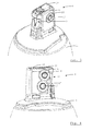
Fig. 2 is a top perspective view of the liquid treatment cartridge at a stage before leaving the factory; -
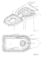
Fig. 3 is a detailed top perspective view of the liquid treatment cartridge at the stage shown inFig. 2 ; -
Fig. 4 is a detailed perspective view from a different direction of the liquid treatment cartridge at the stage shown inFigs. 2 and3 ; -
Fig. 5 is a perspective view of the liquid treatment cartridge with a cap placed on it; -
Fig. 6 is a perspective view of the cap in a state before it is combined with the cartridge; -
Fig. 7 is a detailed top perspective view of the cap in the state in which it is shown inFig. 6 ; -
Fig. 8 is a detailed bottom view of the cap in the state in which it is shown inFigs. 6 and7 ; -
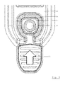
Fig. 9 is a detailed top view of the cap in the state in which it is shown inFigs. 6-8 ; -
Fig. 10 is a top perspective view of the liquid treatment cartridge with the cap placed on it; and -
Fig. 12 is a top perspective view of the cartridge after a cap placed on it has been removed from it. - A
liquid treatment system 1 as shown in the drawings includes ahead part 2 and aliquid treatment cartridge 3. In the example to be described herein, the liquid to be treated is water. Theliquid treatment cartridge 3 includes a housing containing one or more liquid treatment media. - In the example, the liquid treatment media include media for the treatment of liquid by sorption. In particular, the liquid treatment media include at least one ion exchange resin, more particularly a cation exchange resin. The cation exchange resin may be a weakly acidic cation exchange resin at least partly in the hydrogen form, optionally with added cation exchange resin loaded at least initially with potassium to regulate the acidity level of the treated water. The cation exchange resin in the hydrogen form is arranged to remove carbonate or temporary hardness from water passed through it. A fraction of the water passing through the
liquid treatment system 1 bypasses the cation exchange resin in the hydrogen form. It is, however, led through theliquid treatment cartridge 3 and treated by a liquid treatment medium for the treatment of liquid by sorption, this medium including activated carbon. In other examples, theliquid treatment system 1 is alternatively or additionally configured to add components to the liquid, e.g. certain minerals. - The
head part 2 includes aninlet connector 4 for connection to asupply conduit 5. The latter is connected to a source of pressurised water, e.g. the mains water supply. Thehead part 2 also includes anoutlet connector 6 for connection to adelivery conduit 7. Thedelivery conduit 7 is arranged to supply treated liquid to an appliance at a point of use. This appliance may be an appliance for preparing a beverage, e.g. a coffee maker, carbonator, post-mix beverage appliance, water cooler or the like. It may also be a steamer or a dishwasher, for example. Although theinlet connector 4 andoutlet connector 6 allow for disconnection of thehead part 2 from the source of untreated water and the appliance arranged to process the treated water, theliquid treatment system 1 is configured to allow thehead part 2 to remain connected whilst theliquid treatment cartridge 3 is replaced. - To this end, the
liquid treatment cartridge 3 includes a cartridge head 8 (Fig. 2 ) at one end, for insertion into a recess of thehead part 2. Thecartridge head 8 andhead part 2 are provided with co-operating parts (locking features 9 in the case of theliquid treatment cartridge 3 and a latch (not shown) in the case of the head part 2) of a locking mechanism for locking theliquid treatment cartridge 3 in place. The locking mechanism is operated by turninglocking handles 10a,b (Fig. 1 ). - With reference to a central body axis (not shown), the
cartridge head 8 is provided at one axial end of theliquid treatment cartridge 3. A base on which theliquid treatment cartridge 3 shown by way of example can stand is provided at the opposite axial end. Thecartridge head 8 is inserted into thehead part 2 with a generally axially directed movement. - The
cartridge head 8 is an integrally moulded part of acap 11, for example made of a thermoplastic material. In the process of manufacturing theliquid treatment cartridge 3, thecap 11 is combined with a beaker-shapedcartridge housing part 12 after the liquid treatment medium and flow guides (not shown) have been inserted into the beaker-shapedcartridge housing part 12. In particular, the twoparts - The
cartridge head 8 shown here by way of example includes an outlet port 13 (Fig. 3 ) and twoinlet ports 14,15 (Fig. 4 ) through which liquid leaves and enters theliquid treatment cartridge 3, respectively, when a liquid-tight connection between these ports 13-15 and respective ports (not shown) of thehead part 2 has been established. The liquid to be treated is divided into two flows in thehead part 2, one entering theliquid treatment cartridge 3 through amain inlet port 14 and the other entering through abypass inlet port 15. The liquid entering through thebypass inlet port 15 bypasses the liquid treatment medium for removing carbonate hardness. The flows are combined within theliquid treatment cartridge 3, so that there is only oneoutlet port 13. Sealing elements 16-18 are provided to seal the ports 13-15. - It is observed that the
outlet port 13 faces in a direction transverse to the central body axis and theinlet ports cartridge head 8. The ports 13-15 and the locking features 9 are each provided at axial locations short of the axial end of thecartridge head 8 that coincides with the axial end of theliquid treatment cartridge 3. Because none of the ports 13-15 is provided in an axial end face 19 of thecartridge head 8, the locking mechanism locking theliquid treatment cartridge 3 does not have to withstand the pressure of the liquid. - The
axial end face 19 includes a recessed part, within which an integrally mouldedpin 20 is arranged. -
Figs. 2-4 show theliquid treatment cartridge 3 at an intermediate stage in its production process, in which thepin 20 has an essentially circle-cylindrical shape and may protrude slightly with respect to theaxial end face 19. - Before it leaves the factory, the
liquid treatment cartridge 3 is provided with aprotective cap 21, as shown in outline inFig. 5 and in detail inFigs. 10 and 11 .Figs. 6-9 show theprotective cap 21 before it is placed on thecartridge head 8. - The
protective cap 21 has a shape complimentary to that of thecartridge head 8. It includes anend wall 22 and side walls depending therefrom. Integral to theend wall 22 is a separable part including agripping tab 23, a loop-shapedsection 24 and anattachment section 25. The separable part is frangibly connected to theprotective cap 21 such as to be separable from theprotective cap 21. - All frangible connections of the example are provided by lines of weakness shown as dashed lines in
Fig. 9 . The lines of weakness are in the shape of a pattern of reduced thickness in an injection-moulded part comprised of theprotective cap 21 and the separable part. In alternative embodiments, one or more of these connections may be pre-scored or stamped into the composite part comprised of theprotective cap 21 and the separable part. - The gripping
tab 23 is configured for providing purchase on the separable part to a user grabbing hold of it. Several features facilitate this. First, the grippingtab 23 protrudes from theprotective cap 21. In particular, it protrudes laterally from theend wall 22 of theprotective cap 21, to which it is connected via the loop-shapedsection 24. It also projects with respect to afirst side wall 26 depending from theend wall 22. It has a generally planar configuration with its major surface being enlarged due to the fact that it widens where it is joined to the loop-shapedsection 24. Also, raised features are provided on at least one of its major surfaces, in this case in the form of ridges. All this allows a user to exert a pulling force on the separable part, this pulling force being at least partly in a direction transverse to a plane in which the loop-shapedsection 24 lies, and thus also transverse to an outwardly directed face of theend wall 22. As a result, locations at which the frangible connection between the loop-shapedsection 24 and the remainder of theend wall 22 is broken move along the lines of connection indicated inFig. 9 as a pulling force is exerted on the grippingtab 23. The loop-shapedsection 24 is thus separated from theend wall 22. - The loop-shaped
section 24 is also separated from theattachment section 25 in the process, because it extends along a path surrounding theattachment section 25, and is provided with frangible connections on either side of the path. Moreover, a frangible connection interrupting the loop is provided. Theattachment section 25 is retained to thecartridge 3, in this example to thecartridge head 8, since it is irreversible fixed to the latter. - In the illustrated example, the
attachment section 25 is riveted to thecartridge head 8. In the process of manufacturing theliquid treatment cartridge 3, theprotective cap 21 is placed over thecartridge head 8, such that thepin 20 passes through ahole 27 in theattachment section 25 and protrudes slightly from an exposed surface thereof. The protruding end of thepin 20 is then upset, e.g. using a heated tool, such as to rivet the attachment section to thecartridge head 8. A sonotrode can be used instead of a heated tool. - To avoid having the
pin 20 or even theattachment section 25 protrude from the axial end face 19 of thecartridge head 8 when the separable part has been detached from theprotective cap 21, i.e. in the state shown inFig. 12 , theattachment section 25 is set back with respect to at least an adjacent section of the outward-facing surface of theend wall 22 of the cap 21 (cf.Fig. 7 ). Indeed, it is set back by a distance bringing the outward-facing surface of theattachment section 25 to an axial location beyond that of an inward-facing surface of theend wall 22 of theprotective cap 21. This also places it in the recess of thecartridge head 8 in which thepin 20 is provided, when theprotective cap 21 is placed over thecartridge head 8. - It will be clear that the
protective cap 21 is connected to theliquid treatment cartridge 3 in the state in which the latter leaves the factory for installation in the liquid treatment system 1 (Figs. 5 ,10,11 ). The connection is such that theprotective cap 21 can only be removed from theliquid treatment cartridge 3 by first separating the separable part from theprotective cap 21. - Once this has been done, there is an aperture in the
end wall 22, but it remains usable because there are no ports in the axial end face 19 of thecartridge head 8 covered by theend wall 22 of theprotective cap 21. Instead, theinlet ports features second side wall 30 depending from theend wall 22 of theprotective cap 21. Similarly, theoutlet port 13 is closed by a protrudingfeature 31 provided on an inward-facing surface of athird side wall 32 depending from theend wall 22 of theprotective cap 21. The inward-facing surfaces of the second andthird side walls protective cap 21 to fit thecartridge head 8 such that it is deformed elastically to a slight extent as it is slid onto thecartridge head 8. The elastic force acts to urge the second andthird side walls protective cap 21 to close the ports 13-15 when replaced over thecartridge head 8 of a usedliquid treatment cartridge 3. The water remaining therein will thus not spill out during transport of the usedliquid treatment cartridge 3 to a recycling facility. Theside walls protective cap 21 to thecartridge head 8, since they will protrude into at least the respective apertures of the sealing elements 16-18, thus preventing accidental loss of theprotective cap 21 en route. - The used
liquid treatment cartridge 3 with theprotective cap 21 on it is easily distinguished from a newliquid treatment cartridge 3 due to the absence of the grippingtab 23 and the loop-shapedsection 24 of the separable part. - The invention is not limited to the embodiments described above, which may be varied within the scope of the accompanying claims. For example, the
protective cap 21 may be provided with a different type of latching mechanism for removably holding theprotective cap 21 to theliquid treatment cartridge 3 when the separable part has been separated from theprotective cap 21. - The
attachment section 25 may be irreversibly fixed to theliquid treatment cartridge 3 in a different way, e.g. by welding or adhesive bonding. Also, it is possible to configure the separable part such that the action of pulling off theprotective cap 21 separates the separable part from theprotective cap 21, in which case, the separable part can consist essentially of the attachment section, for example. Where an inlet or outlet port is provided in an axial end face of the cartridge head, the separable part could be provided at an axial location short of the axial end wall of the protective cap. It is also possible to provide a snap-fit connection retaining the separable part to the liquid treatment cartridge, in particular the cartridge head part.LIST OF REFERENCE NUMERALS 1 - liquid treatment system 2 - head part 3 - liquid treatment cartridge 4 - inlet connector 5 - supply conduit 6 - outlet connector 7 - delivery conduit 8 - cartridge head 9 - locking features 10a,b - locking handles 11 - cartridge cap 12 - beaker-shaped cartridge housing part 13 - outlet port 14 - main inlet port 15 - bypass inlet port 16 - sealing element for main inlet port 17 - sealing element for bypass inlet port 18 - sealing element for outlet port 19 - axial end face of cartridge head 20 - pin 21 - protective cap 22 - end wall 23 - gripping tab 24 - loop-shaped section 25 - attachment section 26 - 1st side wall 27 - hole 28 - protruding feature 29 - protruding feature 30 - 2nd side wall 31 - protruding feature 32 - 3rd side wall
Claims (15)
- Cap for placement on a cartridge head part (8) of a liquid treatment cartridge (3),
wherein the cartridge head part (8) includes at least one of a liquid inlet port (14,15) and a liquid outlet port (13), and
wherein the cartridge head part (8) is configured for insertion into a head part (2) of a liquid treatment system (1) to establish a liquid-tight connection between at least one of an inlet port and an outlet port of the head part (8) and a corresponding one of the ports (13-15) of the cartridge head part (8),
wherein the cap is configured to cover at least one of the ports (14,15) of the cartridge head part (8) when placed on the cartridge head part (8) with the cartridge head part (8) inserted through an aperture of the cap in an axial direction,
characterised in that
the cap is provided with a part (23-25) having at least one frangible connection to a remainder of the cap and including a section (25) configured to engage the liquid treatment cartridge (3) in a manner enabling it to provide an axial force opposing a force pulling the cap in the axial direction only if the at least one frangible connection is intact. - Cap according to claim 1,
wherein the cap is configured for use with a liquid treatment cartridge having a central axis aligned with the axial direction,
wherein the cap has an end wall (22) for at least partially covering an axial end (19) of the cartridge head part (8) and at least one side wall (26,30,32) depending from the end wall (22) for at least partially covering the cartridge head part (8) laterally,
wherein the part having at least one frangible connection to a remainder of the cap is connected to only one of the end wall (22) and the at least one side wall (26,30,32) and at least one of the other of the end wall (22) and the side wall(s) (26,30,32) is configured to cover at least one of the inlet and outlet ports (13,14,15) in a liquid-tight-manner. - Cap according to claim 1 or 2,
wherein the cap is configured for use with a liquid treatment cartridge (3) having a central axis aligned with the axial direction,
wherein the cap has an end wall (22) for at least partially covering an axial end (19) of the cartridge head part (8) and at least one side wall (26,30,32) depending from the end wall (22) for at least partially covering the cartridge head part (8) laterally, and
wherein at least part of the part having at least one frangible connection to a remainder of the cap is integral to the end wall (22) and connected to a remainder thereof along a line of connection. - Cap according to any one of the preceding claims,
wherein the part (23-25) is separable from the remainder of the cap and the section is an attachment section (25) configured for retainment of at least the attachment section (25) to the liquid treatment cartridge (3). - Cap according to claim 4,
wherein the separable part includes an end section (23) for providing purchase on the separable part; and
a section (24) extending along a path and provided with frangible connections on either side along the path. - Cap according to claim 5,
wherein the attachment section (25) is separable from the section (24) extending along the path at a frangible connection. - Cap according to any one of claims 4-6,
wherein the attachment section (25) is configured for being fixed, for example irreversibly fixed, to the liquid treatment cartridge (3). - Cap according to claim 7,
wherein the attachment section (25) includes a hole (27) for fixing the attachment section (25) to the liquid treatment cartridge (3) by upsetting a pin (20) inserted through the hole (27). - Cap according to any one of claims 4-8,
wherein at least part of the separable part is integral to a wall (22) of the cap and connected to a remainder thereof along a line of connection, and
wherein the attachment section (25) is set back relative to at least an adjacent section of an outward-facing surface of the remainder of the wall (22). - Method of placing a cap (21) according to any one of claims 4-9 on a cartridge head part (8) of a liquid treatment cartridge (3), including connecting the attachment section (25) to the liquid treatment cartridge (3).
- Method according to claim 10,
wherein the attachment section (25) is irreversibly fixed to the liquid treatment cartridge (3) - Method according to claim 11,
wherein the attachment section (25) is fixed to the liquid treatment cartridge (3) by upsetting an end of a pin (20) inserted through a hole (27) in the attachment section (25). - Method according to claim 12,
wherein the pin (20) is a pin (20) moulded on the liquid treatment cartridge (3). - Liquid treatment cartridge, including:a cartridge head part (8),wherein the cartridge head part (8) includes at least one of a liquid inlet port (14,15) and a liquid outlet port (13), andwherein the cartridge head part (8) is configured for insertion into a head part (2) of a liquid treatment system (1) to establish a liquid-tight connection between at least one of an inlet port and an outlet port of the head part (2) and a corresponding one of the ports (13-15) of the cartridge head part (8); anda cap (21), placed over the cartridge head part (8) so as to cover at least one the ports (13-15) of the cartridge head part (8), characterised in thatthe cap (21) is provided with a frangible connection between parts (21,23-25) of the cap (21) and engages the liquid treatment cartridge such as to allow removal of the cap (21) only by breaking the frangible connection.
- Liquid treatment cartridge according to claim 14, wherein the cap (21) is a cap according to any one of claims 1-9.
Priority Applications (1)
| Application Number | Priority Date | Filing Date | Title |
|---|---|---|---|
| EP13164294.4A EP2792612A1 (en) | 2013-04-18 | 2013-04-18 | Cap for a liquid treatment cartridge and method of placing it on the liquid treatment cartridge |
Applications Claiming Priority (1)
| Application Number | Priority Date | Filing Date | Title |
|---|---|---|---|
| EP13164294.4A EP2792612A1 (en) | 2013-04-18 | 2013-04-18 | Cap for a liquid treatment cartridge and method of placing it on the liquid treatment cartridge |
Publications (1)
| Publication Number | Publication Date |
|---|---|
| EP2792612A1 true EP2792612A1 (en) | 2014-10-22 |
Family
ID=48143116
Family Applications (1)
| Application Number | Title | Priority Date | Filing Date |
|---|---|---|---|
| EP13164294.4A Withdrawn EP2792612A1 (en) | 2013-04-18 | 2013-04-18 | Cap for a liquid treatment cartridge and method of placing it on the liquid treatment cartridge |
Country Status (1)
| Country | Link |
|---|---|
| EP (1) | EP2792612A1 (en) |
Citations (3)
| Publication number | Priority date | Publication date | Assignee | Title |
|---|---|---|---|---|
| WO2004056670A1 (en) * | 2002-12-20 | 2004-07-08 | Alto Plastics Limited | Tamper evident closure assemblies |
| WO2008098952A1 (en) * | 2007-02-13 | 2008-08-21 | Brita Gmbh | Device for treating water, particularly a filtration device, and cartridge |
| US20090321340A1 (en) * | 2008-06-25 | 2009-12-31 | Envirogard Products Limited | Filter cartridge for use with a filter head assembly |
-
2013
- 2013-04-18 EP EP13164294.4A patent/EP2792612A1/en not_active Withdrawn
Patent Citations (3)
| Publication number | Priority date | Publication date | Assignee | Title |
|---|---|---|---|---|
| WO2004056670A1 (en) * | 2002-12-20 | 2004-07-08 | Alto Plastics Limited | Tamper evident closure assemblies |
| WO2008098952A1 (en) * | 2007-02-13 | 2008-08-21 | Brita Gmbh | Device for treating water, particularly a filtration device, and cartridge |
| US20090321340A1 (en) * | 2008-06-25 | 2009-12-31 | Envirogard Products Limited | Filter cartridge for use with a filter head assembly |
Similar Documents
| Publication | Publication Date | Title |
|---|---|---|
| US8524078B2 (en) | Water tank and separately formed filter cartridge connection element which can be connected to said water tank | |
| US9132947B2 (en) | Sealing disk for induction sealing a container | |
| US5121778A (en) | Liquid container support and hygienic liquid dispensing system | |
| EP0074184A1 (en) | Handle assembly for a pressurised dispensing container | |
| EP3123905A1 (en) | A lid for a drinking container and the drinking container | |
| US20050236411A1 (en) | Re-sealable can mechanism | |
| CN105263815A (en) | Cap assembly and method for capping same | |
| US20110062106A1 (en) | Closure for a Bottle, and Assembly of Such a Closure and a Bottle | |
| CN105073597B (en) | Method and field installation kit for field installation of a key system | |
| US20060151418A1 (en) | Tamper evident closure assemblies | |
| ES2901782T3 (en) | Closing assembly for a compressible bottle comprising a thermoplastic valve | |
| EP3500518B1 (en) | System for transporting and storing a liquid and for transporting said liquid from the container to a destination outside of the container | |
| EP3181487B1 (en) | Discharge outlet fixing clamp for medium-sized bulk containers | |
| CN117897355A (en) | Tamper-proof dispensing tap by opening the integrated manually-bound security seal | |
| EP1789359B1 (en) | A dispensing line for a dispensing system | |
| US20170045168A1 (en) | Modular fluid connection assembly | |
| EP2822868A1 (en) | Stopper for a container neck | |
| CN101346301A (en) | Locking device and method thereof | |
| CZ300987B6 (en) | Dispensing device and filling method thereof | |
| WO2015004800A1 (en) | Cap assembly and method for assembling same | |
| CN111433137A (en) | Delivery faucet equipped with internal silicone valve including automatic closure with multiple liquid seals and tamper-evident systems | |
| EP1854737B1 (en) | Cartridge for containing and dispensing products in general | |
| KR20100015107A (en) | Apparatus for connecting a house of washer fluid | |
| US10195864B2 (en) | Inkjet printer for the labeling of goods, comprising a filter, and a filter of such an inkjet printer | |
| KR102125279B1 (en) | Coupling device |
Legal Events
| Date | Code | Title | Description |
|---|---|---|---|
| PUAI | Public reference made under article 153(3) epc to a published international application that has entered the european phase |
Free format text: ORIGINAL CODE: 0009012 |
|
| 17P | Request for examination filed |
Effective date: 20130418 |
|
| AK | Designated contracting states |
Kind code of ref document: A1 Designated state(s): AL AT BE BG CH CY CZ DE DK EE ES FI FR GB GR HR HU IE IS IT LI LT LU LV MC MK MT NL NO PL PT RO RS SE SI SK SM TR |
|
| AX | Request for extension of the european patent |
Extension state: BA ME |
|
| RAP1 | Party data changed (applicant data changed or rights of an application transferred) |
Owner name: BRITA GMBH |
|
| STAA | Information on the status of an ep patent application or granted ep patent |
Free format text: STATUS: THE APPLICATION IS DEEMED TO BE WITHDRAWN |
|
| 18D | Application deemed to be withdrawn |
Effective date: 20150423 |