EP2792420B1 - Coating apparatus - Google Patents
Coating apparatus Download PDFInfo
- Publication number
- EP2792420B1 EP2792420B1 EP14158668.5A EP14158668A EP2792420B1 EP 2792420 B1 EP2792420 B1 EP 2792420B1 EP 14158668 A EP14158668 A EP 14158668A EP 2792420 B1 EP2792420 B1 EP 2792420B1
- Authority
- EP
- European Patent Office
- Prior art keywords
- coating
- substrate
- unit
- knife
- pressing
- Prior art date
- Legal status (The legal status is an assumption and is not a legal conclusion. Google has not performed a legal analysis and makes no representation as to the accuracy of the status listed.)
- Active
Links
Images


Classifications
-
- D—TEXTILES; PAPER
- D06—TREATMENT OF TEXTILES OR THE LIKE; LAUNDERING; FLEXIBLE MATERIALS NOT OTHERWISE PROVIDED FOR
- D06B—TREATING TEXTILE MATERIALS USING LIQUIDS, GASES OR VAPOURS
- D06B1/00—Applying liquids, gases or vapours onto textile materials to effect treatment, e.g. washing, dyeing, bleaching, sizing or impregnating
- D06B1/10—Applying liquids, gases or vapours onto textile materials to effect treatment, e.g. washing, dyeing, bleaching, sizing or impregnating by contact with a member carrying the treating material
- D06B1/14—Applying liquids, gases or vapours onto textile materials to effect treatment, e.g. washing, dyeing, bleaching, sizing or impregnating by contact with a member carrying the treating material with a roller
-
- B—PERFORMING OPERATIONS; TRANSPORTING
- B05—SPRAYING OR ATOMISING IN GENERAL; APPLYING FLUENT MATERIALS TO SURFACES, IN GENERAL
- B05C—APPARATUS FOR APPLYING FLUENT MATERIALS TO SURFACES, IN GENERAL
- B05C11/00—Component parts, details or accessories not specifically provided for in groups B05C1/00 - B05C9/00
- B05C11/02—Apparatus for spreading or distributing liquids or other fluent materials already applied to a surface ; Controlling means therefor; Control of the thickness of a coating by spreading or distributing liquids or other fluent materials already applied to the coated surface
- B05C11/04—Apparatus for spreading or distributing liquids or other fluent materials already applied to a surface ; Controlling means therefor; Control of the thickness of a coating by spreading or distributing liquids or other fluent materials already applied to the coated surface with blades
- B05C11/045—Apparatus for spreading or distributing liquids or other fluent materials already applied to a surface ; Controlling means therefor; Control of the thickness of a coating by spreading or distributing liquids or other fluent materials already applied to the coated surface with blades characterised by the blades themselves
-
- B—PERFORMING OPERATIONS; TRANSPORTING
- B05—SPRAYING OR ATOMISING IN GENERAL; APPLYING FLUENT MATERIALS TO SURFACES, IN GENERAL
- B05C—APPARATUS FOR APPLYING FLUENT MATERIALS TO SURFACES, IN GENERAL
- B05C9/00—Apparatus or plant for applying liquid or other fluent material to surfaces by means not covered by any preceding group, or in which the means of applying the liquid or other fluent material is not important
- B05C9/08—Apparatus or plant for applying liquid or other fluent material to surfaces by means not covered by any preceding group, or in which the means of applying the liquid or other fluent material is not important for applying liquid or other fluent material and performing an auxiliary operation
- B05C9/14—Apparatus or plant for applying liquid or other fluent material to surfaces by means not covered by any preceding group, or in which the means of applying the liquid or other fluent material is not important for applying liquid or other fluent material and performing an auxiliary operation the auxiliary operation involving heating or cooling
Definitions
- the present subject matter described herein in general, relates to a coating apparatus and a coating method, and more particularly to a coating apparatus and a method for preparing a coated substrate in a single batch.
- the usual steps involved are coating, drying and finally pressing to improve adhesion of coating. All the stated steps of coating, drying and pressing are generally performed separately. This increases the operation time, makes the process complex with more involvement of manual efforts thereby leading to less reproducibility due to unavoidable manual errors.
- these three steps need to be executed in quick successions to avoid the coating formulation from drying up.
- the coating assembly should also have digital/mechanical control over each of its portion as opposed to the manual control that is most commonly observed in the existing lab coating machines.
- US3507682A describes a coating apparatus for thin film one side coating on a substrate by providing a smoothing roller next to the point where coating solution is applied on the substrate. While the coating is still wet, the smoothing roller rotating in free air in a direction reverse to the movement of the substrate buffs the wet coating so as to form a thin layer of the coating along the length of the substrate.
- the smoothing roller is provided in addition to the application roller, wherein the application roller applies the coating solution on the substrate.
- the smoothing roller rotates in free air and a wiper blade located with respect to the smoothing roller surface removes all but a very thin coating material off the surface of the roller.
- the speed of rotation of the roller, viscosity of the liquid, a speed of the substrate, and extent of tangential contact of the substrate to the roller are coordinated to provide a desired coating on the substrate.
- a point-of-use coating apparatus comprises of the following units, a coating unit, a drying unit, pressing unit and a control unit.
- the coating unit, the drying unit, and the pressing unit are sequentially positioned.
- the coating unit comprises of a coating roller and a knife thereon to apply coating onto a substrate.
- the knife is selected based on the type of coating required i.e. either of knife on air or knife on roll application.
- the knife may have a sharp edge at the bottom and is arranged vertically above the coating roller if the knife on air is selected.
- the knife may have a blunt edge at the bottom, and may be held at 15° with the vertical if the knife on roll is selected.
- a rubber nip roller may be disposed below the coating roller to pull the substrate from an unwind reel.
- the drying unit placed downstream the coating unit comprises of an insulated chamber for drying the coating applied on the substrate.
- the insulate chamber may further comprise a galvanized heater and a thermocouple, configured to maintain a temperature range within 25°C to 200°C.
- the drying unit may comprise of at least one hot air blower for blowing hot air on top and bottom of the substrate and is positioned axially to the drying unit.
- the pressing unit placed downstream with respect to the drying unit comprises a pair of pressing rolls for configured to press the substrate.
- a first pressing roll from the pair of pressing rolls is coated with hard chrome plating and a second pressing roll from the pair of pressing roll is coated with rubber.
- the pair of pressing rolls may be provided with a pressure gauge along with a regulator to maintain a binding pressure on the substrate with the coating.
- the control unit provided with the point-of-use coating apparatus controls operations of the coating, drying and the pressing unit, wherein the control panel is configured to regulate rolling speed of the coating roller and the pair of pressing rolls, and temperatures of the drying unit.
- the coating apparatus comprises of a coating unit, a drying unit and a pressing unit.
- the coating unit further comprises of a knife coater further comprising of knife, wherein said knife is selected based on the type of coating desired on the substrate.
- the drying unit comprises of a dryer with hot air blower, and the pressing unit comprises of a pair of pressing rolls, according to one general embodiment of the present subject matter.
- the presently disclosed subject matter is directed to a probable point-of-use apparatus for production of coated substrate on a laboratory scale, or commercial or industrial or pilot scale.
- substrate may be constructed of plastic, synthetic polymers or fabric, and may be of any size and shape known in the art.
- the substrate treated according to the practice of this invention may vary substantially as to conformation and the flexibility employed.
- the apparatus herein described utilizes a substrate preferably selected from a class of nylons, polyesters, polyamides or aramids.
- coated substrates can be used for protective applications, for example for prevention against lethal chemical warfare agents over an extended period of time and under extremes of environmental attrition not attainable heretofore.
- present coating apparatus can be used for developing a polymeric film on a substrate and also, for preparing a sandwich structured composite (e.g. a composite comprising of a metallized polyester film with substrate).
- a coated substrate is automatically produced in a single batch process at a laboratory scale.
- the coating apparatus engaged for producing such a coated substrate can work efficiently in a laboratory environment without occupying much space with good control over each part of the apparatus.
- the coating apparatus is capable of laying a film-on substrate and even filling the pores of the substrate; drying it at desired temperature for a specified time and eventually pressing the substrate at a suitable pressure to improve the adhesion of coating.
- the coating apparatus as described herein, is capable of monitoring and controlling various coating parameters while preparing the composite, not attainable by known coating apparatuses heretofore.
- the invention contemplates a portable, point-of-use coating apparatus 10 and method of its use as described herein.
- the coating apparatus 10 comprising of a coating unit 20, a drying unit 30 and a pressing unit 40 are arranged sequentially in a single line to accelerate the process of substrate 50 coating.
- the coating unit 20 comprises broadly, of a knife 22 and a coating roller 24.
- the knife 22 is mounted at an adjustable distance above the coating roller 24, wherein the distance between said knife 22 and the coating roller 24 may be adjusted using a dial gauge (not shown in the drawings).
- the coating roller 24 is preferably made of hard-chrome platted mild steel.
- the coating unit 20 is provided with a holding member (not shown in drawings) for holding the mounted knives 22.
- the holding member may be vertical blocks provided with a knife holder to achieve said purpose.
- the vertical blocks with knife holder enable mounting of knife 22 therein and rotating said knife 22 at desired angle while coating the substrate 50.
- the preferred embodiments of the disclosed subject matter involve two kinds of set up for different kind of knife engaged for different application.
- the first set up is for knife 22 (a) that is operable in a coating environment requiring filling the pores of the underlying substrate, henceforth referred to as a knife on air application.
- the alternate set up is for knife 22 (b) that is operable in a coating environment requiring applying a film on the underlying substrate 50, henceforth referred to as a knife on roll application.
- the knives 22(a) and 22(b) involves specific kind of blades for knife on air and knife on roll applications, respectively.
- the blade for knife on air application possesses sharp edge at the bottom.
- the knife 22 (a) should be kept vertical, and preferably away from the coating roller 24.
- the knife 22(a) is held in air so as to fill the pores of the substrate 50 with the coating formulation. This operation does not add to any thickness to the substrate 50, but improves its barrier properties and also, increases the weight of the coated composite.
- Figure 4 shows the layout of the blade used for knife on roll application.
- the blade for knife on roll application has blunt edge which should be kept at 15° with the vertical during the coating application, also shown in Figure 6 .
- the blade is fixed just above the coating roller 24 to prepare a film of coating formulation on the substrate 50. This improves the barrier properties of the substrate 50 and adds to the overall weight and thickness of the coated composite.
- the gap between the knife 22 and coating roller 24 can be smoothly adjusted with the help of dial gauge to control thickness of the coating.
- the maximum width of the substrate 50 is limited by the width of coating roller 24 and the knives 22 (a) and 22(b); and a coated composite up to 300 mm width can be prepared by this kind of coating apparatus 10.
- a pneumatically operated rubber nip roller 54 is attached just below the coating roller 24 to pull the substrate 50 from an unwind reel.
- a sample holder 52 is placed just above the coating roller 24 to keep the coating on the substrate 50.
- the substrate 50 is held tightly by the coating roller 24 at one end and the pressing roller 40 at the other end. Both the rollers can be operated by gearbox and A.C. motor to move the substrate 50 at desired speed in the forward direction to have a uniform coating on the substrate 50.
- the drying unit 30 is shaped like a rectangular box and is directly connected downstream to the coating unit 20.
- Two electric fin type galvanized heaters 32 as shown in Figure 1 , are used to generate temperature within a range preferably varying from 25°C to 200°C inside the dryer.
- the axial blowers (not shown in the drawings), made of stainless steel, are employed to blow hot air through nozzles on top 36(a) and bottom 36(b) of the substrate 50. This facility provides faster drying of the substrate 50 after coating.
- the insulation panel inside the drying unit 30 restricts heat loss and maintains uniform temperature throughout the dryer.
- a "J" type thermocouple (not shown in the diagrams) is inserted into the hot air blower section to maintain desired temperature with the help of a temperature controller, installed inside the control panel.
- the main frame of the pressing unit 40 is made of mild steel and connected with cross supports.
- the pressing unit 40 consists of a pair of pressing rolls, a first pressing roll 42 (a) and a second pressing roll 42(b), wherein a first pressing roll 42(a) is coated with hard chrome plating (diameter 87 mm) and fixed inside the frame of the pressing unit 40. It can be rotated by gearbox and A.C. motor, attached onto the frame.
- the second pressing roll 42(b) is pneumatically operated and is coated with rubber; preferably with diameter 75 mm.
- the second pressing roll 42(b) is installed over the first pressing roll 42(a) is.
- a pressure gauge along with a regulator is used to maintain desired pressure (up to 7 kg-f/cm 2 ) on the coated substrate 50.
- the control panel is fabricated out of M.S. sheet and is coated with powder. It consists of an A.C. variable drive for adjusting the speed of coating roller 24 and the pair of pressing rolls 42(a) and 42(b) with necessary switch gears.
- the temperature controller for the dryer and controller for the blowers are also installed inside the control panel.
- a method for applying coating upon an underlying substrate 50 utilizing the coating apparatus 10 is disclosed.
- the substrate 50 is first cleaned thoroughly before applying coating thereon to remove dirt, grease or any other contaminants on its surface since the untreated substrate 50 may yield poor bonding between the substrate and the coating.
- the pretreated substrate 50 is then made to undergo the coating process on a single coating line.
- the substrate 50 is made to pass through the gap between rubber nip roller 54 and coating roller 24 with knife 22 over its surface, in the coating unit 20.
- the substrate passes between top 36(a) and bottom 36(b) nozzles.
- the pressing unit 40 the substrate is made to pass between hard chrome platted first pressing roll 42(a) and rubber coated second pressing roll 42(b).
- the substrate 50 may be mounted tightly with the coating rollers 24 and the pair of pressing rolls 42(a) and 42(b).
- the angle of the knife 22, and the gap between the knife 22 and coating roller 24 can be variably adjusted using a dial gauge. It may be noted that for knife on air application, the blade should be kept vertical and placed away from the coating roller 24 ( Figure 5 ). The lower edge of the blade must be kept just below the plane of the substrate 50. For knife on roll application, the blade should be kept at 15° with the vertical and it should preferably lie just above the coating roller 24 ( Figure 6 ).
- the pressure on the pair of pressing roll 42(a) and 42(b) should be set depending on the application requirement.
- the speed of the coating roller 24 and the pair of pressing roll 42(a) and 42(b) maybe set after that.
- maintaining the speed of the pair of pressing roll 42(a) and 42(b) higher than that of the coating roller 24 ensures that the substrate 50 is at tension in the coating line throughout the coating operation.
- the drying/curing temperature inside the drying unit 30 can then be fixed with the temperature controller inside the control panel.
- the hot air blower should not be put on at that time.
- the coating apparatus 10 is now ready for coating development on the substrate 50.
- the coating formulation is fed to the substrate sample holder 52 followed by rotation of the rolls in the forward direction.
- the substrate 50 is moved in the forward direction resulting into the formation of coating of desired thickness on the substrate 50.
- the coated composite is then sent inside the drying unit 30 and the hot air blower is switched on.
- the hot air blow from top and bottom of the substrate 50 ensures faster drying of the coated composite.
- the hot composite is pressed using pressing rolls 40. For pasting a metallized film on the substrate 50, the film is passed along with the coated composite through the pair of pressing roll 42(a) and 42(b).
- the embodiments of the present disclosure can be used for preparing uniform coating of pastes, resins, silicones, adhesives, inks, polymers etc. on different types of substrates like textile fabric, cloth, paper etc.
- the instrument is useful in preparing coated composites at laboratory scale or industrial scale.
- the disclosed coating apparatus can produce coated substrate in a single batch process, with sufficient control over each portion of the apparatus.
- the same coating line can be further used for laminating different sheets of material.
- the point-of-use coating apparatus comprises a coating unit, wherein the coating unit further comprises a coating roller and vertical blocks, wherein the vertical blocks form a seat for mounting a knife thereon to apply coating onto a substrate.
- a drying unit is placed downstream of the coating unit, wherein the drying unit further comprises an insulated chamber for drying the coating applied on the substrate.
- the point-of-use coating also comprises a pressing unit, wherein the pressing unit further comprises a pair of pressing rolls, wherein the pair of pressing roll improve binding of the coating with the substrate.
- a control unit for controlling operations of the coating, drying and the pressing unit is included in the point-of-use coating apparatus.
- the control panel may be configured to regulate rolling speed of the coating roller and the pair of pressing rolls, and, temperatures of the drying unit and the hot air blowers.
- the point-of-use apparatus of the present disclosure may have the coating unit, the drying unit, and the pressing unit sequentially positioned.
- the point-of-use coating apparatus may have a rubber nip roller 54 adapted to be disposed below the coating roller to pull the substrate from an unwind reel.
- a sample holder 52 may be arranged to be held above the coating roller to keep the coating on the substrate.
- the coating roller according to present implementation may be made up of hard chrome platted mild steel.
- the knife of the present disclosure may comprise a blade, wherein the knife selected for coating may be based on type of application, the application could either be a knife on air application, or a knife on roll application.
- the blade used for knife on air application may possess a sharp edge at the bottom, and is arranged vertically above the coating roll at an adjustable distance.
- the blade used for knife on roll application possesses may have a blunt edge at the bottom, and is held at 15° with the vertical.
- the insulated chamber of the present disclosure may comprise a galvanized heater and a thermocouple.
- the galvanized heater and the thermocouple may be configured to maintain a temperature range within 25°C to 200°C.
- the drying unit may comprise at least one hot air blower positioned axially to the drying unit for blowing hot air on top and bottom of the substrate.
- a first pressing roll from the pair of pressing roll can be coated with hard chrome plating and a second pressing roll from the pair of pressing roll may be coated with rubber.
- the second pressing roll may be installed over the first pressing roll.
- the pair of pressing rolls may be provided with a pressure gauge along with a regulator to maintain a binding pressure on the substrate with the coating. The pressure could be maintained approximately up to 7 kg-f/cm 2 .
- the knife and the coating roller of the present apparatus may be adjusted using a dial gauge.
Description
- The present subject matter described herein, in general, relates to a coating apparatus and a coating method, and more particularly to a coating apparatus and a method for preparing a coated substrate in a single batch.
- For developing a composite fabric at various locations, such as laboratories, the usual steps involved are coating, drying and finally pressing to improve adhesion of coating. All the stated steps of coating, drying and pressing are generally performed separately. This increases the operation time, makes the process complex with more involvement of manual efforts thereby leading to less reproducibility due to unavoidable manual errors. In addition, for some applications, these three steps need to be executed in quick successions to avoid the coating formulation from drying up. Thus, there is a need to design and fabricate a compact coating unit with all these features arranged sequentially such that the entire assembly can be accommodated in the laboratory settings. The coating assembly should also have digital/mechanical control over each of its portion as opposed to the manual control that is most commonly observed in the existing lab coating machines.
- Various kinds of industrial knife coating machines are mentioned in different literature reports. However, for all the devices mentioned above, the coating processes are complex requiring several units arranged in series, which eventually occupies a lot of space. Such machines are thence not suitable for small/lab scale applications.
-
US3507682A describes a coating apparatus for thin film one side coating on a substrate by providing a smoothing roller next to the point where coating solution is applied on the substrate. While the coating is still wet, the smoothing roller rotating in free air in a direction reverse to the movement of the substrate buffs the wet coating so as to form a thin layer of the coating along the length of the substrate. The smoothing roller is provided in addition to the application roller, wherein the application roller applies the coating solution on the substrate. The smoothing roller rotates in free air and a wiper blade located with respect to the smoothing roller surface removes all but a very thin coating material off the surface of the roller. The speed of rotation of the roller, viscosity of the liquid, a speed of the substrate, and extent of tangential contact of the substrate to the roller are coordinated to provide a desired coating on the substrate. - This summary is provided to introduce aspects related to a coating apparatus that is capable of preparing coated composites in a single process, and the aspects are further described below in the detailed description. While the aspects of the present disclosure contemplates using the coating apparatus, as disclosed herein at the laboratory scale, the apparatus can nevertheless be employed at industrial or commercial scales, as will be apparent to those skilled in the art from the disclosure here-below. This summary is not intended to identify essential features of the claimed subject matter nor is it intended for use in determining or limiting the scope of the claimed subject matter.
- The present invention comprises a coating apparatus as defined in claim 1. In one implementation, a point-of-use coating apparatus is provided that broadly comprises of the following units, a coating unit, a drying unit, pressing unit and a control unit. The coating unit, the drying unit, and the pressing unit are sequentially positioned. The coating unit comprises of a coating roller and a knife thereon to apply coating onto a substrate. The knife is selected based on the type of coating required i.e. either of knife on air or knife on roll application. The knife may have a sharp edge at the bottom and is arranged vertically above the coating roller if the knife on air is selected. The knife may have a blunt edge at the bottom, and may be held at 15° with the vertical if the knife on roll is selected. A rubber nip roller may be disposed below the coating roller to pull the substrate from an unwind reel. The drying unit placed downstream the coating unit comprises of an insulated chamber for drying the coating applied on the substrate. The insulate chamber may further comprise a galvanized heater and a thermocouple, configured to maintain a temperature range within 25°C to 200°C. The drying unit may comprise of at least one hot air blower for blowing hot air on top and bottom of the substrate and is positioned axially to the drying unit. Further, the pressing unit placed downstream with respect to the drying unit comprises a pair of pressing rolls for configured to press the substrate. A first pressing roll from the pair of pressing rolls is coated with hard chrome plating and a second pressing roll from the pair of pressing roll is coated with rubber. The pair of pressing rolls may be provided with a pressure gauge along with a regulator to maintain a binding pressure on the substrate with the coating.
- The control unit provided with the point-of-use coating apparatus controls operations of the coating, drying and the pressing unit, wherein the control panel is configured to regulate rolling speed of the coating roller and the pair of pressing rolls, and temperatures of the drying unit.
- The foregoing summary, as well as the following detailed description of preferred embodiments, is better understood when read in conjunction with the appended drawings. For the purpose of illustrating the invention, there is shown in the drawings example constructions of the invention; however, the invention is not limited to the specific coating apparatus disclosed in the drawings. In the drawings, the left-most digit(s) of a reference number identifies the drawings in which the reference number first appears. The same numbers are used throughout the drawings to refer like features and components.
-
Figure 1 shows a top plan view of the coating apparatus, in accordance with an embodiment of the present subject matter. -
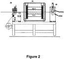
Figure 2 presents a side view of the coating apparatus, in accordance with an embodiment of the present subject matter. -
Figure 3 shows a front view and a side view of blade used for knife on air application, in accordance with an embodiment of the present subject matter. -
Figure 4 shows a front view and a side view of blade used for knife on roll application, in accordance with an embodiment of the present subject matter. -
Figure 5 shows a set-up for knife on air application. -
Figure 6 shows a set-up for knife on roll application. - Some embodiments of this invention, illustrating all its features, will now be discussed in detail. The words "comprising," "having," "containing," and "including," and other forms thereof, are intended to be equivalent in meaning and be open ended in that an item or items following any one of these words is not meant to be an exhaustive listing of such item or items, or meant to be limited to only the listed item or items.
- It must also be noted that as used herein and in the appended claims, the singular forms "a," "an," and "the" include plural references unless the context clearly dictates otherwise. Although any systems and methods similar or equivalent to those described herein can be used in the practice or testing of embodiments of the present invention, the preferred, systems and methods are now described.
- The present invention is not to be limited in scope by the specific embodiments described herein, since such embodiments are intended as but single illustrations of one aspect of the invention and any functionally equivalent embodiments are within the scope of this invention. Thence, the embodiments though mention employing of the coating apparatus at laboratory settings, indeed, various modifications to the apparatus to employ at the progressive industrial level, in addition to those shown and described herein will become apparent to those skilled in the art from the foregoing description.
- Broadly, the coating apparatus, disclosed herein, comprises of a coating unit, a drying unit and a pressing unit. The coating unit further comprises of a knife coater further comprising of knife, wherein said knife is selected based on the type of coating desired on the substrate. The drying unit comprises of a dryer with hot air blower, and the pressing unit comprises of a pair of pressing rolls, according to one general embodiment of the present subject matter.
- In one embodiment, the presently disclosed subject matter is directed to a probable point-of-use apparatus for production of coated substrate on a laboratory scale, or commercial or industrial or pilot scale. The term "substrate" may be constructed of plastic, synthetic polymers or fabric, and may be of any size and shape known in the art. The substrate treated according to the practice of this invention may vary substantially as to conformation and the flexibility employed. Illustratively, the apparatus herein described utilizes a substrate preferably selected from a class of nylons, polyesters, polyamides or aramids.
- The primary advantage of the coated substrates is that they can be used for protective applications, for example for prevention against lethal chemical warfare agents over an extended period of time and under extremes of environmental attrition not attainable heretofore. Furthermore, the present coating apparatus can be used for developing a polymeric film on a substrate and also, for preparing a sandwich structured composite (e.g. a composite comprising of a metallized polyester film with substrate).
- In one embodiment of the present invention, a coated substrate is automatically produced in a single batch process at a laboratory scale. The coating apparatus engaged for producing such a coated substrate can work efficiently in a laboratory environment without occupying much space with good control over each part of the apparatus. The coating apparatus is capable of laying a film-on substrate and even filling the pores of the substrate; drying it at desired temperature for a specified time and eventually pressing the substrate at a suitable pressure to improve the adhesion of coating. In addition, the coating apparatus, as described herein, is capable of monitoring and controlling various coating parameters while preparing the composite, not attainable by known coating apparatuses heretofore.
- Referring now to
Figure 1 &2 , a top view and the side view of thecoating apparatus 10 is illustrated, in accordance with an embodiment of the present subject matter. In one embodiment, the invention contemplates a portable, point-of-use coating apparatus 10 and method of its use as described herein. In the preferred embodiment, thecoating apparatus 10 comprising of acoating unit 20, a dryingunit 30 and apressing unit 40 are arranged sequentially in a single line to accelerate the process ofsubstrate 50 coating. - Re-referring to
Figure 1 &2 , thecoating unit 20, comprises broadly, of aknife 22 and acoating roller 24. In one implementation, theknife 22 is mounted at an adjustable distance above thecoating roller 24, wherein the distance between saidknife 22 and thecoating roller 24 may be adjusted using a dial gauge (not shown in the drawings). Thecoating roller 24 is preferably made of hard-chrome platted mild steel. In an alternate embodiment, thecoating unit 20 is provided with a holding member (not shown in drawings) for holding the mountedknives 22. The holding member, may be vertical blocks provided with a knife holder to achieve said purpose. In one given embodiment, the vertical blocks with knife holder enable mounting ofknife 22 therein and rotating saidknife 22 at desired angle while coating thesubstrate 50. - The preferred embodiments of the disclosed subject matter involve two kinds of set up for different kind of knife engaged for different application. The first set up is for knife 22 (a) that is operable in a coating environment requiring filling the pores of the underlying substrate, henceforth referred to as a knife on air application. The alternate set up is for knife 22 (b) that is operable in a coating environment requiring applying a film on the
underlying substrate 50, henceforth referred to as a knife on roll application. The knives 22(a) and 22(b) involves specific kind of blades for knife on air and knife on roll applications, respectively. - As shown in
Figure 3 , the blade for knife on air application possesses sharp edge at the bottom. During coating application, the knife 22 (a) should be kept vertical, and preferably away from thecoating roller 24. Also shown inFigure 5 , the knife 22(a) is held in air so as to fill the pores of thesubstrate 50 with the coating formulation. This operation does not add to any thickness to thesubstrate 50, but improves its barrier properties and also, increases the weight of the coated composite. - Next,
Figure 4 shows the layout of the blade used for knife on roll application. The blade for knife on roll application has blunt edge which should be kept at 15° with the vertical during the coating application, also shown inFigure 6 . The blade is fixed just above thecoating roller 24 to prepare a film of coating formulation on thesubstrate 50. This improves the barrier properties of thesubstrate 50 and adds to the overall weight and thickness of the coated composite. - Vertical blocks are provided with the knife holder to mount both the knives 22(a) and 22(b) and allow them to rotate at desired angle. The gap between the
knife 22 andcoating roller 24 can be smoothly adjusted with the help of dial gauge to control thickness of the coating. The maximum width of thesubstrate 50 is limited by the width ofcoating roller 24 and the knives 22 (a) and 22(b); and a coated composite up to 300 mm width can be prepared by this kind ofcoating apparatus 10. - As can be seen from
Figure 5 & 6 , a pneumatically operated rubber niproller 54 is attached just below thecoating roller 24 to pull thesubstrate 50 from an unwind reel. A sample holder 52 is placed just above thecoating roller 24 to keep the coating on thesubstrate 50. Thesubstrate 50 is held tightly by thecoating roller 24 at one end and thepressing roller 40 at the other end. Both the rollers can be operated by gearbox and A.C. motor to move thesubstrate 50 at desired speed in the forward direction to have a uniform coating on thesubstrate 50. - The drying
unit 30 is shaped like a rectangular box and is directly connected downstream to thecoating unit 20. Two electric fin type galvanizedheaters 32, as shown inFigure 1 , are used to generate temperature within a range preferably varying from 25°C to 200°C inside the dryer. The axial blowers (not shown in the drawings), made of stainless steel, are employed to blow hot air through nozzles on top 36(a) and bottom 36(b) of thesubstrate 50. This facility provides faster drying of thesubstrate 50 after coating. The insulation panel inside the dryingunit 30 restricts heat loss and maintains uniform temperature throughout the dryer. A "J" type thermocouple (not shown in the diagrams) is inserted into the hot air blower section to
maintain desired temperature with the help of a temperature controller, installed inside the control panel. - The main frame of the
pressing unit 40 is made of mild steel and connected with cross supports. Thepressing unit 40 consists of a pair of pressing rolls, a first pressing roll 42 (a) and a second pressing roll 42(b), wherein a first pressing roll 42(a) is coated with hard chrome plating (diameter 87 mm) and fixed inside the frame of thepressing unit 40. It can be rotated by gearbox and A.C. motor, attached onto the frame. The second pressing roll 42(b) is pneumatically operated and is coated with rubber; preferably with diameter 75 mm. The second pressing roll 42(b) is installed over the first pressing roll 42(a) is. A pressure gauge along with a regulator is used to maintain desired pressure (up to 7 kg-f/cm2) on thecoated substrate 50. - The control panel is fabricated out of M.S. sheet and is coated with powder. It consists of an A.C. variable drive for adjusting the speed of
coating roller 24 and the pair of pressing rolls 42(a) and 42(b) with necessary switch gears. The temperature controller for the dryer and controller for the blowers are also installed inside the control panel. - In one implementation, a method for applying coating upon an
underlying substrate 50 utilizing thecoating apparatus 10 is disclosed. Thesubstrate 50 is first cleaned thoroughly before applying coating thereon to remove dirt, grease or any other contaminants on its surface since theuntreated substrate 50 may yield poor bonding between the substrate and the coating. The pretreatedsubstrate 50 is then made to undergo the coating process on a single coating line. - In one general implementation, the
substrate 50 is made to pass through the gap between rubber niproller 54 andcoating roller 24 withknife 22 over its surface, in thecoating unit 20. Next, in the dryingunit 30 the substrate passes between top 36(a) and bottom 36(b) nozzles. Finally, in thepressing unit 40, the substrate is made to pass between hard chrome platted first pressing roll 42(a) and rubber coated second pressing roll 42(b). - The
substrate 50 may be mounted tightly with thecoating rollers 24 and the pair of pressing rolls 42(a) and 42(b). The angle of theknife 22, and the gap between theknife 22 andcoating roller 24 can be variably adjusted using a dial gauge. It may be noted that for knife on air application, the blade should be kept vertical and placed away from the coating roller 24 (Figure 5 ). The lower edge of the blade must be kept just below the plane of thesubstrate 50. For knife on roll application, the blade should be kept at 15° with the vertical and it should preferably lie just above the coating roller 24 (Figure 6 ). - Next, the pressure on the pair of pressing roll 42(a) and 42(b) should be set depending on the application requirement. The speed of the
coating roller 24 and the pair of pressing roll 42(a) and 42(b) maybe set after that. Preferably, maintaining the speed of the pair of pressing roll 42(a) and 42(b) higher than that of thecoating roller 24 ensures that thesubstrate 50 is at tension in the coating line throughout the coating operation. - The drying/curing temperature inside the drying
unit 30 can then be fixed with the temperature controller inside the control panel. The hot air blower, however, should not be put on at that time. - The
coating apparatus 10 is now ready for coating development on thesubstrate 50. The coating formulation is fed to the substrate sample holder 52 followed by rotation of the rolls in the forward direction. As a result, thesubstrate 50 is moved in the forward direction resulting into the formation of coating of desired thickness on thesubstrate 50. The coated composite is then sent inside the dryingunit 30 and the hot air blower is switched on. The hot air blow from top and bottom of thesubstrate 50 ensures faster drying of the coated composite. Finally, the hot composite is pressed usingpressing rolls 40. For pasting a metallized film on thesubstrate 50, the film is passed along with the coated composite through the pair of pressing roll 42(a) and 42(b). - The embodiments of the present disclosure can be used for preparing uniform coating of pastes, resins, silicones, adhesives, inks, polymers etc. on different types of substrates like textile fabric, cloth, paper etc. Significantly, the instrument is useful in preparing coated composites at laboratory scale or industrial scale. The disclosed coating apparatus can produce coated substrate in a single batch process, with sufficient control over each portion of the apparatus. The same coating line can be further used for laminating different sheets of material.
- In another implementation, the point-of-use coating apparatus comprises a coating unit, wherein the coating unit further comprises a coating roller and vertical blocks, wherein the vertical blocks form a seat for mounting a knife thereon to apply coating onto a substrate. A drying unit is placed downstream of the coating unit, wherein the drying unit further comprises an insulated chamber for drying the coating applied on the substrate. The point-of-use coating also comprises a pressing unit, wherein the pressing unit further comprises a pair of pressing rolls, wherein the pair of pressing roll improve binding of the coating with the substrate. A control unit for controlling operations of the coating, drying and the pressing unit is included in the point-of-use coating apparatus. The control panel may be configured to regulate rolling speed of the coating roller and the pair of pressing rolls, and, temperatures of the drying unit and the hot air blowers.
- The point-of-use apparatus of the present disclosure may have the coating unit, the drying unit, and the pressing unit sequentially positioned. The point-of-use coating apparatus may have a rubber nip
roller 54 adapted to be disposed below the coating roller to pull the substrate from an unwind reel. A sample holder 52 may be arranged to be held above the coating roller to keep the coating on the substrate. The coating roller according to present implementation may be made up of hard chrome platted mild steel. - The knife of the present disclosure may comprise a blade, wherein the knife selected for coating may be based on type of application, the application could either be a knife on air application, or a knife on roll application. The blade used for knife on air application may possess a sharp edge at the bottom, and is arranged vertically above the coating roll at an adjustable distance. In another implementation the blade used for knife on roll application possesses may have a blunt edge at the bottom, and is held at 15° with the vertical.
- The insulated chamber of the present disclosure may comprise a galvanized heater and a thermocouple. The galvanized heater and the thermocouple may be configured to maintain a temperature range within 25°C to 200°C. The drying unit may comprise at least one hot air blower positioned axially to the drying unit for blowing hot air on top and bottom of the substrate.
- A first pressing roll from the pair of pressing roll can be coated with hard chrome plating and a second pressing roll from the pair of pressing roll may be coated with rubber. The second pressing roll may be installed over the first pressing roll. The pair of pressing rolls may be provided with a pressure gauge along with a regulator to maintain a binding pressure on the substrate with the coating. The pressure could be maintained approximately up to 7 kg-f/cm2. The knife and the coating roller of the present apparatus may be adjusted using a dial gauge.
Claims (9)
- A coating apparatus (10) comprising:a coating unit (20), wherein the coating unit (20) comprises a coating roller (24) and a knife (22) thereon, to apply a coating onto a substrate (50), wherein the knife (22) further comprises:a sharp edged blade and a blunt edged blade which are selectable based on the type of coating application, wherein the coating unit is configured to provide:a knife on air (22(a)) coating application wherein the sharp edged blade is used for filling the pores of the substrate (50); anda knife on roll (22(b)) coating application wherein the blunt edged blade is used for applying a film on the surface of the substrate (50);a drying unit (30) placed downstream with respect to the coating unit (20), wherein the drying unit (30) comprises an insulated chamber for drying the coating applied to the substrate (50);a pressing unit (40) placed downstream with respect to the drying unit (30), wherein the pressing unit (40) comprises a pair of pressing rolls (42(a) and 42(b)) configured to press the substrate (50) with the coating, and to apply a binding pressure on the substrate with the coating to obtain adhesion of the coating to the substrate, and wherein the pair of pressing rolls (42(a) and 42(b)) comprise a first pressing roll (42(a)) coated with hard chrome plating and a second pressing roll (42(b)) coated with rubber, and wherein the speed of the pair of pressing rolls (42(a) and 42(b)) is higher than the speed of the coating roller (24) in order to maintain a tension on the substrate and control a moving speed of the substrate to achieve uniformity of the coating; anda control unit for controlling operations of the coating unit (20), the drying unit (30) and the pressing unit (40), wherein the control unit is further configured to regulate a rolling speed of the coating roller (24) and the pair of pressing rolls (42(a) and 42(b)), and a temperature of the drying unit (30).
- The coating apparatus (10) of claim 1, wherein the coating unit (20), the drying unit (30), and the pressing unit (40) are sequentially positioned.
- The coating apparatus (10) of claim 1, wherein a rubber nip roller (54) is disposed below the coating roller (24) to pull the substrate from an unwind reel.
- The coating apparatus (10) of claim 1, wherein the coating roller (24) is made of hard chrome platted mild steel.
- The coating apparatus (10) of claim 1, wherein the knife on air (22(a)) has a sharp edge thereof, and the knife on air is arranged vertically above the coating roller (24) at an adjustable distance.
- The coating apparatus (10) of claim 1, wherein the knife on roll (22(b)) has a blunt edge, and the knife on roll (22(b)) is held at 15° with a vertical.
- The coating apparatus (10) of claim 1, wherein the drying unit (30) maintains a temperature in a range within 25°C to 200°C.
- The coating apparatus (10) of claim 1, wherein the binding pressure is maintained upto 7 kg-f/cm<2>.
- The coating apparatus of claim 1, wherein a gap between the knife and the coating roller is adjusted to control the thickness of the coating.
Applications Claiming Priority (1)
| Application Number | Priority Date | Filing Date | Title |
|---|---|---|---|
| IN1209MU2013 IN2013MU01209A (en) | 2013-03-28 | 2013-03-28 |
Publications (2)
| Publication Number | Publication Date |
|---|---|
| EP2792420A1 EP2792420A1 (en) | 2014-10-22 |
| EP2792420B1 true EP2792420B1 (en) | 2018-05-02 |
Family
ID=50236112
Family Applications (1)
| Application Number | Title | Priority Date | Filing Date |
|---|---|---|---|
| EP14158668.5A Active EP2792420B1 (en) | 2013-03-28 | 2014-03-10 | Coating apparatus |
Country Status (3)
| Country | Link |
|---|---|
| US (1) | US9611575B2 (en) |
| EP (1) | EP2792420B1 (en) |
| IN (1) | IN2013MU01209A (en) |
Families Citing this family (1)
| Publication number | Priority date | Publication date | Assignee | Title |
|---|---|---|---|---|
| DE212020000200U1 (en) * | 2020-09-17 | 2020-10-08 | Suzhou Mochou Culture Technology Co., Ltd. | A device for textile coating processing |
Family Cites Families (17)
| Publication number | Priority date | Publication date | Assignee | Title |
|---|---|---|---|---|
| US2780563A (en) * | 1952-12-08 | 1957-02-05 | Warren S D Co | Method for cast calendering supercalendered coated paper |
| NL297070A (en) * | 1962-08-23 | |||
| US3507682A (en) * | 1967-06-19 | 1970-04-21 | Ncr Co | Process and apparatus for coating thin film substrates |
| DE2843371C2 (en) * | 1978-10-05 | 1985-07-11 | Zanders Feinpapiere AG, 5060 Bergisch Gladbach | Process for coating running webs of paper or cardboard with customary pigment dispersions and a device for adjusting the wet application weight of coatings, in particular for carrying out the process |
| US4354810A (en) * | 1980-11-24 | 1982-10-19 | Polysar Incorporated | Apparatus for distributing a foamed composition on a substrate |
| GB8822049D0 (en) * | 1988-09-20 | 1988-10-19 | Stoddard Sekers Int | Doctor blade apparatus |
| US5447566A (en) * | 1993-12-27 | 1995-09-05 | Autographic Business Forms, Inc. | Paper coating and drying machine |
| US6395335B2 (en) * | 1996-12-10 | 2002-05-28 | Matsushita Electric Industrial Co., Ltd. | Apparatus and method for printing solder paste |
| US6381874B1 (en) * | 2000-10-13 | 2002-05-07 | Continental Girbau, Inc. | Tumbler for clothes dryer |
| US7669547B2 (en) * | 2001-03-14 | 2010-03-02 | 3M Innovative Properties Company | Coating apparatus |
| KR20050063279A (en) | 2003-12-22 | 2005-06-28 | 손상 | Processing method and apparatus for coating of texting |
| JP4344638B2 (en) * | 2004-03-26 | 2009-10-14 | 富士フイルム株式会社 | Antireflection film, manufacturing method thereof, manufacturing apparatus |
| FI20045295A (en) * | 2004-08-13 | 2006-02-14 | Avantone Oy | Embossing device and method for adjusting an embossing device |
| US7625605B2 (en) * | 2004-12-30 | 2009-12-01 | 3M Innovative Properties Company | Method for coating a surface with a pattern of coating fluid |
| US8312834B2 (en) * | 2005-04-14 | 2012-11-20 | Hamilton Sundstrand Corporation | Apparatus for applying thin coating |
| JP2009236355A (en) | 2008-03-26 | 2009-10-15 | Fujifilm Corp | Drying method and device |
| JP5595823B2 (en) | 2010-07-30 | 2014-09-24 | 富士フイルム株式会社 | Image forming method and image forming apparatus |
-
2013
- 2013-03-28 IN IN1209MU2013 patent/IN2013MU01209A/en unknown
-
2014
- 2014-03-10 EP EP14158668.5A patent/EP2792420B1/en active Active
- 2014-03-10 US US14/202,711 patent/US9611575B2/en not_active Expired - Fee Related
Non-Patent Citations (1)
| Title |
|---|
| None * |
Also Published As
| Publication number | Publication date |
|---|---|
| EP2792420A1 (en) | 2014-10-22 |
| US20140290570A1 (en) | 2014-10-02 |
| IN2013MU01209A (en) | 2015-04-10 |
| US9611575B2 (en) | 2017-04-04 |
Similar Documents
| Publication | Publication Date | Title |
|---|---|---|
| US4213930A (en) | Method for increasing the surface tack of prepreg materials | |
| EP2910381B1 (en) | Liquid discharge device and media pretreatment method | |
| CN107428059B (en) | The manufacturing method of micro- porous plastic film | |
| HU191741B (en) | Method and apparatus for applying partial surface layers | |
| CN201404897Y (en) | Multi-purpose dividing and cutting machine with coating function | |
| CN106715114A (en) | Method for adhesively bonding two sheet-like substrates | |
| EP2792420B1 (en) | Coating apparatus | |
| KR20170103407A (en) | High-speed Lamination Apparatus | |
| EP2759484A1 (en) | Vacuum drum, particularly for a roll-fed labelling machine, and vacuum drum pad | |
| US2793677A (en) | Laminating apparatus | |
| US9016232B2 (en) | Paper coating apparatus with multiple hot wax applicators and associated methods | |
| GB2213406A (en) | Coating apparatus | |
| US4238533A (en) | Coating process and apparatus | |
| CN110039869A (en) | A kind of novel three layers of composite coating machine | |
| US10183309B1 (en) | Method and apparatus for impregnating a continuous fiber reinforcement | |
| US7927442B2 (en) | Method and apparatus for producing an insulation support with an adhesive layer for a magnetic resonance gradient coil | |
| CN216511984U (en) | Coating and rubber-coating processing device for silicone rubber coiled material | |
| CN106914387A (en) | Conveyer belt manufacture method | |
| JP2013202455A (en) | Coating method | |
| CN208303152U (en) | A kind of polyester film reagent spray painting device | |
| CN208558710U (en) | A kind of production line of stamp album patch | |
| US5795386A (en) | Apparatus for applying a coating layer to a substrate web | |
| TW416907B (en) | Method and apparatus for manufacturing prepreg | |
| EP4035870A1 (en) | Method and machine for wrapping profiles with a wrapping poil | |
| EP2846930A1 (en) | Method and device for levelling and establishing the thickness of a liquid agent layer spread on a material |
Legal Events
| Date | Code | Title | Description |
|---|---|---|---|
| PUAI | Public reference made under article 153(3) epc to a published international application that has entered the european phase |
Free format text: ORIGINAL CODE: 0009012 |
|
| 17P | Request for examination filed |
Effective date: 20140310 |
|
| AK | Designated contracting states |
Kind code of ref document: A1 Designated state(s): AL AT BE BG CH CY CZ DE DK EE ES FI FR GB GR HR HU IE IS IT LI LT LU LV MC MK MT NL NO PL PT RO RS SE SI SK SM TR |
|
| AX | Request for extension of the european patent |
Extension state: BA ME |
|
| R17P | Request for examination filed (corrected) |
Effective date: 20150422 |
|
| RBV | Designated contracting states (corrected) |
Designated state(s): AL AT BE BG CH CY CZ DE DK EE ES FI FR GB GR HR HU IE IS IT LI LT LU LV MC MK MT NL NO PL PT RO RS SE SI SK SM TR |
|
| STAA | Information on the status of an ep patent application or granted ep patent |
Free format text: STATUS: EXAMINATION IS IN PROGRESS |
|
| 17Q | First examination report despatched |
Effective date: 20170215 |
|
| GRAP | Despatch of communication of intention to grant a patent |
Free format text: ORIGINAL CODE: EPIDOSNIGR1 |
|
| STAA | Information on the status of an ep patent application or granted ep patent |
Free format text: STATUS: GRANT OF PATENT IS INTENDED |
|
| INTG | Intention to grant announced |
Effective date: 20171123 |
|
| GRAS | Grant fee paid |
Free format text: ORIGINAL CODE: EPIDOSNIGR3 |
|
| GRAA | (expected) grant |
Free format text: ORIGINAL CODE: 0009210 |
|
| STAA | Information on the status of an ep patent application or granted ep patent |
Free format text: STATUS: THE PATENT HAS BEEN GRANTED |
|
| AK | Designated contracting states |
Kind code of ref document: B1 Designated state(s): AL AT BE BG CH CY CZ DE DK EE ES FI FR GB GR HR HU IE IS IT LI LT LU LV MC MK MT NL NO PL PT RO RS SE SI SK SM TR |
|
| RAP1 | Party data changed (applicant data changed or rights of an application transferred) |
Owner name: TATA CONSULTANCY SERVICES LIMITED |
|
| REG | Reference to a national code |
Ref country code: GB Ref legal event code: FG4D |
|
| REG | Reference to a national code |
Ref country code: CH Ref legal event code: EP Ref country code: AT Ref legal event code: REF Ref document number: 994642 Country of ref document: AT Kind code of ref document: T Effective date: 20180515 |
|
| RAP2 | Party data changed (patent owner data changed or rights of a patent transferred) |
Owner name: TATA CONSULTANCY SERVICES LIMITED |
|
| REG | Reference to a national code |
Ref country code: DE Ref legal event code: R096 Ref document number: 602014024733 Country of ref document: DE |
|
| REG | Reference to a national code |
Ref country code: IE Ref legal event code: FG4D |
|
| REG | Reference to a national code |
Ref country code: NL Ref legal event code: MP Effective date: 20180502 |
|
| REG | Reference to a national code |
Ref country code: LT Ref legal event code: MG4D |
|
| PG25 | Lapsed in a contracting state [announced via postgrant information from national office to epo] |
Ref country code: ES Free format text: LAPSE BECAUSE OF FAILURE TO SUBMIT A TRANSLATION OF THE DESCRIPTION OR TO PAY THE FEE WITHIN THE PRESCRIBED TIME-LIMIT Effective date: 20180502 Ref country code: NO Free format text: LAPSE BECAUSE OF FAILURE TO SUBMIT A TRANSLATION OF THE DESCRIPTION OR TO PAY THE FEE WITHIN THE PRESCRIBED TIME-LIMIT Effective date: 20180802 Ref country code: SE Free format text: LAPSE BECAUSE OF FAILURE TO SUBMIT A TRANSLATION OF THE DESCRIPTION OR TO PAY THE FEE WITHIN THE PRESCRIBED TIME-LIMIT Effective date: 20180502 Ref country code: BG Free format text: LAPSE BECAUSE OF FAILURE TO SUBMIT A TRANSLATION OF THE DESCRIPTION OR TO PAY THE FEE WITHIN THE PRESCRIBED TIME-LIMIT Effective date: 20180802 Ref country code: FI Free format text: LAPSE BECAUSE OF FAILURE TO SUBMIT A TRANSLATION OF THE DESCRIPTION OR TO PAY THE FEE WITHIN THE PRESCRIBED TIME-LIMIT Effective date: 20180502 Ref country code: LT Free format text: LAPSE BECAUSE OF FAILURE TO SUBMIT A TRANSLATION OF THE DESCRIPTION OR TO PAY THE FEE WITHIN THE PRESCRIBED TIME-LIMIT Effective date: 20180502 |
|
| PG25 | Lapsed in a contracting state [announced via postgrant information from national office to epo] |
Ref country code: GR Free format text: LAPSE BECAUSE OF FAILURE TO SUBMIT A TRANSLATION OF THE DESCRIPTION OR TO PAY THE FEE WITHIN THE PRESCRIBED TIME-LIMIT Effective date: 20180803 Ref country code: NL Free format text: LAPSE BECAUSE OF FAILURE TO SUBMIT A TRANSLATION OF THE DESCRIPTION OR TO PAY THE FEE WITHIN THE PRESCRIBED TIME-LIMIT Effective date: 20180502 Ref country code: LV Free format text: LAPSE BECAUSE OF FAILURE TO SUBMIT A TRANSLATION OF THE DESCRIPTION OR TO PAY THE FEE WITHIN THE PRESCRIBED TIME-LIMIT Effective date: 20180502 Ref country code: HR Free format text: LAPSE BECAUSE OF FAILURE TO SUBMIT A TRANSLATION OF THE DESCRIPTION OR TO PAY THE FEE WITHIN THE PRESCRIBED TIME-LIMIT Effective date: 20180502 Ref country code: RS Free format text: LAPSE BECAUSE OF FAILURE TO SUBMIT A TRANSLATION OF THE DESCRIPTION OR TO PAY THE FEE WITHIN THE PRESCRIBED TIME-LIMIT Effective date: 20180502 |
|
| REG | Reference to a national code |
Ref country code: AT Ref legal event code: MK05 Ref document number: 994642 Country of ref document: AT Kind code of ref document: T Effective date: 20180502 |
|
| PG25 | Lapsed in a contracting state [announced via postgrant information from national office to epo] |
Ref country code: RO Free format text: LAPSE BECAUSE OF FAILURE TO SUBMIT A TRANSLATION OF THE DESCRIPTION OR TO PAY THE FEE WITHIN THE PRESCRIBED TIME-LIMIT Effective date: 20180502 Ref country code: CZ Free format text: LAPSE BECAUSE OF FAILURE TO SUBMIT A TRANSLATION OF THE DESCRIPTION OR TO PAY THE FEE WITHIN THE PRESCRIBED TIME-LIMIT Effective date: 20180502 Ref country code: DK Free format text: LAPSE BECAUSE OF FAILURE TO SUBMIT A TRANSLATION OF THE DESCRIPTION OR TO PAY THE FEE WITHIN THE PRESCRIBED TIME-LIMIT Effective date: 20180502 Ref country code: AT Free format text: LAPSE BECAUSE OF FAILURE TO SUBMIT A TRANSLATION OF THE DESCRIPTION OR TO PAY THE FEE WITHIN THE PRESCRIBED TIME-LIMIT Effective date: 20180502 Ref country code: EE Free format text: LAPSE BECAUSE OF FAILURE TO SUBMIT A TRANSLATION OF THE DESCRIPTION OR TO PAY THE FEE WITHIN THE PRESCRIBED TIME-LIMIT Effective date: 20180502 Ref country code: PL Free format text: LAPSE BECAUSE OF FAILURE TO SUBMIT A TRANSLATION OF THE DESCRIPTION OR TO PAY THE FEE WITHIN THE PRESCRIBED TIME-LIMIT Effective date: 20180502 Ref country code: SK Free format text: LAPSE BECAUSE OF FAILURE TO SUBMIT A TRANSLATION OF THE DESCRIPTION OR TO PAY THE FEE WITHIN THE PRESCRIBED TIME-LIMIT Effective date: 20180502 |
|
| REG | Reference to a national code |
Ref country code: DE Ref legal event code: R097 Ref document number: 602014024733 Country of ref document: DE |
|
| PG25 | Lapsed in a contracting state [announced via postgrant information from national office to epo] |
Ref country code: IT Free format text: LAPSE BECAUSE OF FAILURE TO SUBMIT A TRANSLATION OF THE DESCRIPTION OR TO PAY THE FEE WITHIN THE PRESCRIBED TIME-LIMIT Effective date: 20180502 Ref country code: SM Free format text: LAPSE BECAUSE OF FAILURE TO SUBMIT A TRANSLATION OF THE DESCRIPTION OR TO PAY THE FEE WITHIN THE PRESCRIBED TIME-LIMIT Effective date: 20180502 |
|
| PLBE | No opposition filed within time limit |
Free format text: ORIGINAL CODE: 0009261 |
|
| STAA | Information on the status of an ep patent application or granted ep patent |
Free format text: STATUS: NO OPPOSITION FILED WITHIN TIME LIMIT |
|
| 26N | No opposition filed |
Effective date: 20190205 |
|
| PG25 | Lapsed in a contracting state [announced via postgrant information from national office to epo] |
Ref country code: SI Free format text: LAPSE BECAUSE OF FAILURE TO SUBMIT A TRANSLATION OF THE DESCRIPTION OR TO PAY THE FEE WITHIN THE PRESCRIBED TIME-LIMIT Effective date: 20180502 |
|
| PG25 | Lapsed in a contracting state [announced via postgrant information from national office to epo] |
Ref country code: MC Free format text: LAPSE BECAUSE OF FAILURE TO SUBMIT A TRANSLATION OF THE DESCRIPTION OR TO PAY THE FEE WITHIN THE PRESCRIBED TIME-LIMIT Effective date: 20180502 |
|
| PG25 | Lapsed in a contracting state [announced via postgrant information from national office to epo] |
Ref country code: AL Free format text: LAPSE BECAUSE OF FAILURE TO SUBMIT A TRANSLATION OF THE DESCRIPTION OR TO PAY THE FEE WITHIN THE PRESCRIBED TIME-LIMIT Effective date: 20180502 Ref country code: LU Free format text: LAPSE BECAUSE OF NON-PAYMENT OF DUE FEES Effective date: 20190310 |
|
| REG | Reference to a national code |
Ref country code: BE Ref legal event code: MM Effective date: 20190331 |
|
| PG25 | Lapsed in a contracting state [announced via postgrant information from national office to epo] |
Ref country code: IE Free format text: LAPSE BECAUSE OF NON-PAYMENT OF DUE FEES Effective date: 20190310 |
|
| PG25 | Lapsed in a contracting state [announced via postgrant information from national office to epo] |
Ref country code: BE Free format text: LAPSE BECAUSE OF NON-PAYMENT OF DUE FEES Effective date: 20190331 |
|
| PG25 | Lapsed in a contracting state [announced via postgrant information from national office to epo] |
Ref country code: TR Free format text: LAPSE BECAUSE OF FAILURE TO SUBMIT A TRANSLATION OF THE DESCRIPTION OR TO PAY THE FEE WITHIN THE PRESCRIBED TIME-LIMIT Effective date: 20180502 |
|
| PG25 | Lapsed in a contracting state [announced via postgrant information from national office to epo] |
Ref country code: MT Free format text: LAPSE BECAUSE OF NON-PAYMENT OF DUE FEES Effective date: 20190310 Ref country code: PT Free format text: LAPSE BECAUSE OF FAILURE TO SUBMIT A TRANSLATION OF THE DESCRIPTION OR TO PAY THE FEE WITHIN THE PRESCRIBED TIME-LIMIT Effective date: 20180903 |
|
| PG25 | Lapsed in a contracting state [announced via postgrant information from national office to epo] |
Ref country code: CY Free format text: LAPSE BECAUSE OF FAILURE TO SUBMIT A TRANSLATION OF THE DESCRIPTION OR TO PAY THE FEE WITHIN THE PRESCRIBED TIME-LIMIT Effective date: 20180502 |
|
| PGFP | Annual fee paid to national office [announced via postgrant information from national office to epo] |
Ref country code: GB Payment date: 20210324 Year of fee payment: 8 |
|
| PG25 | Lapsed in a contracting state [announced via postgrant information from national office to epo] |
Ref country code: IS Free format text: LAPSE BECAUSE OF FAILURE TO SUBMIT A TRANSLATION OF THE DESCRIPTION OR TO PAY THE FEE WITHIN THE PRESCRIBED TIME-LIMIT Effective date: 20180902 |
|
| PG25 | Lapsed in a contracting state [announced via postgrant information from national office to epo] |
Ref country code: HU Free format text: LAPSE BECAUSE OF FAILURE TO SUBMIT A TRANSLATION OF THE DESCRIPTION OR TO PAY THE FEE WITHIN THE PRESCRIBED TIME-LIMIT; INVALID AB INITIO Effective date: 20140310 |
|
| PG25 | Lapsed in a contracting state [announced via postgrant information from national office to epo] |
Ref country code: MK Free format text: LAPSE BECAUSE OF FAILURE TO SUBMIT A TRANSLATION OF THE DESCRIPTION OR TO PAY THE FEE WITHIN THE PRESCRIBED TIME-LIMIT Effective date: 20180502 |
|
| GBPC | Gb: european patent ceased through non-payment of renewal fee |
Effective date: 20220310 |
|
| PG25 | Lapsed in a contracting state [announced via postgrant information from national office to epo] |
Ref country code: GB Free format text: LAPSE BECAUSE OF NON-PAYMENT OF DUE FEES Effective date: 20220310 |
|
| PGFP | Annual fee paid to national office [announced via postgrant information from national office to epo] |
Ref country code: FR Payment date: 20230323 Year of fee payment: 10 |
|
| PGFP | Annual fee paid to national office [announced via postgrant information from national office to epo] |
Ref country code: DE Payment date: 20230322 Year of fee payment: 10 |
|
| P01 | Opt-out of the competence of the unified patent court (upc) registered |
Effective date: 20230526 |
|
| PGFP | Annual fee paid to national office [announced via postgrant information from national office to epo] |
Ref country code: CH Payment date: 20230402 Year of fee payment: 10 |