EP2792304B1 - Medical examination-cum-surgery table - Google Patents
Medical examination-cum-surgery table Download PDFInfo
- Publication number
- EP2792304B1 EP2792304B1 EP12858004.0A EP12858004A EP2792304B1 EP 2792304 B1 EP2792304 B1 EP 2792304B1 EP 12858004 A EP12858004 A EP 12858004A EP 2792304 B1 EP2792304 B1 EP 2792304B1
- Authority
- EP
- European Patent Office
- Prior art keywords
- fixing
- releasing
- guide rails
- releasing mechanism
- medical treatment
- Prior art date
- Legal status (The legal status is an assumption and is not a legal conclusion. Google has not performed a legal analysis and makes no representation as to the accuracy of the status listed.)
- Active
Links
- 238000001356 surgical procedure Methods 0.000 title description 2
- 230000007246 mechanism Effects 0.000 claims description 80
- 238000011282 treatment Methods 0.000 claims description 45
- 230000003028 elevating effect Effects 0.000 claims description 10
- 230000036632 reaction speed Effects 0.000 claims description 5
- 239000000463 material Substances 0.000 claims description 3
- XEEYBQQBJWHFJM-UHFFFAOYSA-N Iron Chemical compound [Fe] XEEYBQQBJWHFJM-UHFFFAOYSA-N 0.000 description 8
- 238000010586 diagram Methods 0.000 description 4
- 229910052742 iron Inorganic materials 0.000 description 4
- 238000012276 Endovascular treatment Methods 0.000 description 2
- 230000000712 assembly Effects 0.000 description 2
- 238000000429 assembly Methods 0.000 description 2
- 230000005540 biological transmission Effects 0.000 description 2
- 239000002184 metal Substances 0.000 description 2
- 229910052751 metal Inorganic materials 0.000 description 2
- OKTJSMMVPCPJKN-UHFFFAOYSA-N Carbon Chemical compound [C] OKTJSMMVPCPJKN-UHFFFAOYSA-N 0.000 description 1
- 210000004204 blood vessel Anatomy 0.000 description 1
- 229910052799 carbon Inorganic materials 0.000 description 1
- 230000000694 effects Effects 0.000 description 1
- 238000005516 engineering process Methods 0.000 description 1
- 230000035515 penetration Effects 0.000 description 1
Images

Classifications
-
- A—HUMAN NECESSITIES
- A61—MEDICAL OR VETERINARY SCIENCE; HYGIENE
- A61B—DIAGNOSIS; SURGERY; IDENTIFICATION
- A61B6/00—Apparatus for radiation diagnosis, e.g. combined with radiation therapy equipment
- A61B6/04—Positioning of patients; Tiltable beds or the like
- A61B6/0407—Supports, e.g. tables or beds, for the body or parts of the body
- A61B6/0442—Supports, e.g. tables or beds, for the body or parts of the body made of non-metallic materials
-
- A—HUMAN NECESSITIES
- A61—MEDICAL OR VETERINARY SCIENCE; HYGIENE
- A61B—DIAGNOSIS; SURGERY; IDENTIFICATION
- A61B6/00—Apparatus for radiation diagnosis, e.g. combined with radiation therapy equipment
- A61B6/04—Positioning of patients; Tiltable beds or the like
- A61B6/0407—Supports, e.g. tables or beds, for the body or parts of the body
-
- A—HUMAN NECESSITIES
- A61—MEDICAL OR VETERINARY SCIENCE; HYGIENE
- A61G—TRANSPORT, PERSONAL CONVEYANCES, OR ACCOMMODATION SPECIALLY ADAPTED FOR PATIENTS OR DISABLED PERSONS; OPERATING TABLES OR CHAIRS; CHAIRS FOR DENTISTRY; FUNERAL DEVICES
- A61G13/00—Operating tables; Auxiliary appliances therefor
- A61G13/0018—Physician's examining tables
-
- A—HUMAN NECESSITIES
- A61—MEDICAL OR VETERINARY SCIENCE; HYGIENE
- A61G—TRANSPORT, PERSONAL CONVEYANCES, OR ACCOMMODATION SPECIALLY ADAPTED FOR PATIENTS OR DISABLED PERSONS; OPERATING TABLES OR CHAIRS; CHAIRS FOR DENTISTRY; FUNERAL DEVICES
- A61G13/00—Operating tables; Auxiliary appliances therefor
- A61G13/02—Adjustable operating tables; Controls therefor
- A61G13/04—Adjustable operating tables; Controls therefor tiltable around transverse or longitudinal axis
-
- A—HUMAN NECESSITIES
- A61—MEDICAL OR VETERINARY SCIENCE; HYGIENE
- A61G—TRANSPORT, PERSONAL CONVEYANCES, OR ACCOMMODATION SPECIALLY ADAPTED FOR PATIENTS OR DISABLED PERSONS; OPERATING TABLES OR CHAIRS; CHAIRS FOR DENTISTRY; FUNERAL DEVICES
- A61G13/00—Operating tables; Auxiliary appliances therefor
- A61G13/10—Parts, details or accessories
-
- A—HUMAN NECESSITIES
- A61—MEDICAL OR VETERINARY SCIENCE; HYGIENE
- A61B—DIAGNOSIS; SURGERY; IDENTIFICATION
- A61B6/00—Apparatus for radiation diagnosis, e.g. combined with radiation therapy equipment
- A61B6/04—Positioning of patients; Tiltable beds or the like
- A61B6/0487—Motor-assisted positioning
-
- A—HUMAN NECESSITIES
- A61—MEDICAL OR VETERINARY SCIENCE; HYGIENE
- A61B—DIAGNOSIS; SURGERY; IDENTIFICATION
- A61B6/00—Apparatus for radiation diagnosis, e.g. combined with radiation therapy equipment
- A61B6/10—Application or adaptation of safety means
-
- A—HUMAN NECESSITIES
- A61—MEDICAL OR VETERINARY SCIENCE; HYGIENE
- A61B—DIAGNOSIS; SURGERY; IDENTIFICATION
- A61B6/00—Apparatus for radiation diagnosis, e.g. combined with radiation therapy equipment
- A61B6/44—Constructional features of apparatus for radiation diagnosis
- A61B6/4405—Constructional features of apparatus for radiation diagnosis the apparatus being movable or portable, e.g. handheld or mounted on a trolley
-
- A—HUMAN NECESSITIES
- A61—MEDICAL OR VETERINARY SCIENCE; HYGIENE
- A61G—TRANSPORT, PERSONAL CONVEYANCES, OR ACCOMMODATION SPECIALLY ADAPTED FOR PATIENTS OR DISABLED PERSONS; OPERATING TABLES OR CHAIRS; CHAIRS FOR DENTISTRY; FUNERAL DEVICES
- A61G13/00—Operating tables; Auxiliary appliances therefor
- A61G13/10—Parts, details or accessories
- A61G13/104—Adaptations for table mobility, e.g. arrangement of wheels
-
- A—HUMAN NECESSITIES
- A61—MEDICAL OR VETERINARY SCIENCE; HYGIENE
- A61G—TRANSPORT, PERSONAL CONVEYANCES, OR ACCOMMODATION SPECIALLY ADAPTED FOR PATIENTS OR DISABLED PERSONS; OPERATING TABLES OR CHAIRS; CHAIRS FOR DENTISTRY; FUNERAL DEVICES
- A61G2210/00—Devices for specific treatment or diagnosis
- A61G2210/50—Devices for specific treatment or diagnosis for radiography
Definitions
- the present invention relates to a medical treatment and surgical operation table, and more specifically, to a table commonly usable for medial treatment and surgical operation in which the table is freely movable in a horizontal direction and freely inclinable.
- a known surgical operation table and a known medical treatment table have different functions from each other because of difference in their use.
- a medical treatment table used for an X-ray apparatus as one example to be provided with a function such that a doctor can optionally move a table, in a horizontal direction, on which a patient is laid, for observation of an imaged portion with the X-ray transmitting a specified part of a body of the patient (see Patent Document 1).
- a surgical operation table it is necessary for a surgical operation table to be movable to a position at which a doctor can perform surgical treatment to a specific part of a patient body (i.e., it is necessary to change the position (posture) of the patient, and because of such reason, it is required for the table on which the patient is laid to be provided with a function of being vertically movable or inclinable (see Patent Document 2).
- an object of the present invention is to provide a medical treatment and surgical operation table (medical treatment/ surgical operation table) functioning commonly as medical treatment table and surgical operation table.
- the medical treatment and surgical operation table (2) includes: a table (40) which is formed of a material through which an X-ray transmits and on which a patient lays; an operation unit (10) that supports a lower side of one end portion of the table and operates the table so as to elevate, incline and move in all direction in a horizontal plane; a base (5) that supports the operation unit; and fixing/releasing means (65) that fixes movement of the table or moves the fixed table by magnetic force.
- the table is provided with a function as the medical treatment table and a function as a surgical operation table, so that an emergent surgical operation after the medical treatment can be smoothly undergone.
- the medical treatment and surgical operation table according to claim 2 in that of claim 1 further includes another fixing/ releasing means (75) that fixes movement of the table or moves the fixed table, the another fixing/ releasing means having a fixing force for fixing the movement of the table larger than that of the first mentioned fixing/ releasing means, wherein the movement of the table is fixed by the first mentioned fixing/ releasing means at a time when the table is in a horizontal state, and at a time when the table is in an inclined state, the movement of the table is fixed by the another fixing/releasing means.
- the table since in a state in which the table is largely inclined, the fixing/ releasing means having a large fixing force is operated, the table is superior in safeness.
- the first mentioned fixing/ releasing means has a reaction speed for fixing the movement of the table or moving the fixed table faster than that of the another fixing/releasing means.
- the table fixing operation and the table releasing operation can be promptly performed, thus being convenient for an operator.
- a plurality of fixing/releasing means may be provided, in which in the table being in the horizontal state, the movement of the table is fixed by at least selected one of the plural fixing/ releasing means, and in the table being in the inclined state, the movement of the table is fixed by all the fixing/releasing means.
- the table can be easily controlled with a different fixing force in the table horizontal state and the table inclining state.
- the table of the present invention is provided with the function for operating as medical treatment table and surgical operation table, an operator can be easily handled and is hence available for an emergent surgical operation after the medical treatment.
- a left-right direction is mentioned as an X-direction and a front-back direction of the medical treatment table
- a vertical direction is mentioned as a Z-direction and a vertical direction of the medical treatment table
- a front/depth direction is mentioned as a Y-direction and a left-right direction of the medical treatment table.
- the medical treatment table in the present embodiment is a table that is usable for a doctor in a field of the endovascular treatment using an X-ray apparatus.
- the present embodiment is not limited to such field and the table may be of course usable for a general surgical operation table or a general medical treatment table.
- a medical treatment and surgical operation table 2 of the present embodiment is provided with a base 5, a table operation unit 10 mounted on the base 5, a table 40 mounted on the table operation unit 10.
- Casters 6 may be equipped for lower four corners of the base 5 as occasion demands, and according to the attaching of these casters 6, the medical treatment and surgical operation table 2 is freely movable on a floor.
- a case 3 in which a control device for electrically controlling the medical treatment and surgical operation table 2 and other members or like are accommodated, is mounted to the base 5.
- the case 3 is provided, on its surface, with a cover member 3a to be openable and closable, and a button or other parts, not shown, for electrically controlling the medical treatment and surgical operation table are optionally arranged inside the cover member 3a.
- the table 40 is made of a carbon or like material capable of transmitting an X-ray and composed of one sheet plate-like member having a size by which a patient laying on the table can be supported.
- the table 40 is provided with a frame 42 covering the side portion of a rear end of the table so as to support the table 40 in the horizontal direction.
- the table 40 has a structure, except the rear end portion, not damaged by the transmission of the X-ray in its perpendicular direction. Further, for example, a head portion of a patient is placed on the front portion of the table 40 and a leg portion of the patient is placed on the rear portion thereof.
- the table operation unit 10 is, as shown in Figs. 1 to 4 , disposed on a lower portion of the table frame 42 and is provided with a plurality of operating mechanisms for performing various operations of the table 40.
- the operating mechanisms include an elevating mechanism 15 for vertically elevating the table 40, an inclining mechanism 25 for freely inclining the table 40, and a horizontally movable mechanism 35 for moving the table in the horizontal direction with hands.
- the elevating mechanism 15 is arranged, as shown in Fig. 2 , above the base 5 to be expanded or contracted in the perpendicular direction, and as shown with arrow, to be adjustable in height level of the table in accordance with a height of a doctor.
- the inclining mechanism 25 is positioned above the elevating mechanism 15 and coupled with the table via a laterally turning shaft 26 and a longitudinally turning shaft 27 in a manner such that the table 40 can be laterally turned with the laterally turning shaft 26 being fulcrum while longitudinally turned with the longitudinally turning shaft 27 being fulcrum as shown in Fig. 6 .
- the inclination of the table 40 can be adjusted by a doctor to thereby change a posture of the patient at which the doctor can easily treat the patient.
- the horizontally movable mechanism 35 is positioned, as shown in Figs. 2 , 4 , 7 and 8 , above the inclining mechanism 25 so as to freely slide the table with hands in the longitudinally and laterally horizontal direction to thereby move the position of the patient, i.e., table 40, in the horizontally all directions thereof.
- the elevating mechanism 15 is provided, as shown in Fig. 2 with dotted line, with a rod member 16 including a plurality of rods 16a and 16b combined to be expanded and contracted in the perpendicular direction between the base 5 and the inclining mechanism 25, and a hydraulic cylinder assembly 17 which slides the rod 16b in the vertical direction with respect to the rods 16a.
- the rod member 16 and the hydraulic cylinder assembly 17 are entirely covered by a vertically expandable cover 18.
- the hydraulic cylinder assembly 17 is driven, the rod member 16 combined with the rods 16a and 16b is expanded or contracted to thereby vertically elevate the table 40 to a desired height level.
- the inclining mechanism 25 is arranged, as shown in Figs. 5 and 6 , between the elevating mechanism 15 and the horizontally movable mechanism 35 and provided with a housing 28 by which the laterally turning shaft 26 and the longitudinally turning shaft 27 are held.
- the housing 28 has a box-shaped structure substantially in form of rectangular parallelepiped shape, and is coupled with a bracket 85 upwardly standing from an upper end of the elevating mechanism 15 via the laterally turning shaft 26.
- the longitudinally turning shaft 27 is provided on each side of the horizontally arranged housing 28 perpendicular to the laterally turning shaft 26 so as to project outward in the horizontal direction, and the tip end of the longitudinally turning shafts 27 are coupled with left and right (lateral) downwardly directed brackets 29 projecting perpendicularly from the lower end of the horizontally movable mechanism 35.
- a pin 31 is provided at a perpendicularly upper portion of the laterally turning shaft 26 in a manner held by the housing 28, and a rod is connected to the pin 31 provided with hydraulic cylinder assemblies 32 and 33 in laterally symmetric arrangement with respect to the laterally turning shaft 26.
- the rod pushes the pin 31 to thereby incline the table 40 in the lateral direction with a predetermined inclination with the laterally turning shaft being the fulcrum.
- a hydraulic cylinder assembly 34 is arranged so as to expand or contract a rod 34a in the perpendicular direction between the elevating mechanism 15 and the horizontally movable mechanism 35.
- the hydraulic cylinder assembly 34 is driven, the length of the rod 34a is expanded or contracted so as to incline the front and rear portions of the table 40 at the predetermined inclination with the longitudinally turning shaft 27 being the fulcrum.
- the horizontally movable mechanism 35 is provided with a lower side housing 35a arranged above the inclining mechanism 25 and an upper side housing 35b attached to an upper end portion of the lower side housing to be slidable and coupled with the table 40.
- an upper support member 36, a central support member 37 and a lower support member 38 are provided respectively with the upper end portion of the upper side hosing 35b, a boundary portion between the upper side housing 35b and the lower side housing 35a, and the lower end portion of the lower side housing 35a with predetermined intervals, respectively, in the horizontal direction.
- two vertical guide rails 51 arranged in parallel are attached to the upper support member (bracket) 36 so as to extend in the X-direction on both lateral side end portions within the upper side housing 35b.
- a plurality of guide rail support members 52 supporting the vertical guide rails 51 to be slidable on both lateral sides are mounted with equal interval to the center support member 37.
- the guide rails 51 are freely movable in the X-direction, and according to the movement of the guide rails 51, the upper support member 36 and the table 40 becomes movable in the front-and-rear (longitudinal) direction.
- three horizontal guide rails 54 arranged in parallel with equal interval are attached to the center support member 37 so as to extend in the lateral direction within the lower side housing 35a.
- a plurality of guide rail support members 55 supporting the horizontal guide rails 54 to be slidable on both lateral sides are mounted with equal interval to the lower support member 38.
- the guide rails 54 are freely movable in the Y-direction, and according to the movement of the guide rails 51, the upper support member 36 and the table 40 becomes movable in the lateral direction.
- the horizontally movable mechanism 35 having the structure mentioned above, when an operator manually handles the table 40 in the longitudinal or lateral direction, the vertical guide rails 51 or horizontal guide rails 54 are moved within the respective support members 52, 55 for these guide rails to thereby freely move the table 40 in all the directions in the horizontal plane.
- the medical treatment and surgical operation table 2 is provided with, as shown in Fig. 7(a) , a fixing/releasing mechanism 60 for fixing the table 40 that is movable in the horizontal direction and releasing such fixing of the table for allowing the table to be movable.
- the fixing/releasing mechanism 60 includes a first fixing/releasing mechanism 65 and a second fixing/releasing mechanism 75 having different fixing force for fixing the movement of the table by the operator, in which the first fixing/ releasing mechanism 65 has a fixing force larger than that of the second fixing/releasing mechanism 75 and has a fixing/releasing time (i.e., speed) slower than that of the second fixing/ releasing mechanism.
- the first fixing/releasing mechanism 65 is one for fixing the movement of the table by utilizing magnetic force, and as shown in Fig. 9 , includes an iron plate 66 attached to the upper support member 36 and having a magnetic force, a permanent magnet 68 pushed against a support member 67 attached to the lower support member 38 with a spring force, a coil 69 arranged around the permanent magnet, and a cover member 70 arranged apart from the iron plate so as to cover the permanent magnet 68 and the coil 69.
- the movement of the table 40 is fixed by adsorbing the permanent magnet 68 (cover member 70) arranged apart from the iron plate 66. Further, on the other hand, by applying current to the coil 69, the magnetic force of the permanent magnet 68 is neutralized and the permanent magnet 68 is separated from the iron plate 66 to thereby release the fixing of the table to be movable.
- first fixing/releasing mechanism 65 is merely composed of a permanent magnet and a coil, it may be composed of a mechanism generally called an electromagnet.
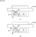
- the second fixing/releasing mechanism 75 includes, as shown in Fig. 10 , a motor 77 including a rotating shaft 76, a cam 78 that is moved by the rotation of the rotating shaft 76, a pin 79 engaging the cam 78, and a push member 80 for pushing at least one side surface of the guide rails 51 and 54 arranged between the cam 78 and the guide rails 51 and 54.
- the rotating shaft 76 of the motor 77 is expanded or contracted to thereby move the cam 78, and hence, the push member 80 pushes the one side surface of the guide rails 51, 54 by the pin 79 engaged with the inclination surface 78a formed to the cam 78, thereby fixing the movement of the guide rails 51 and 54.
- the cam 78 is moved to the original position by reverse rotation of the motor , the push member is separated from the side surfaces of the guide rails 51 and 54, so that the fixing of the guide rails 51 and 54 is released to be movable.
- the table 40 when the table 40 is moved in the horizontal direction, it is required for the table 40 to be promptly fixed and/or for the fixed table to be promptly moved, and when the table 40 is inclined, it is required for the table to have high fixing force so as not to be moved. Therefore, in the present embodiment, it is desirable to use the first fixing/releasing mechanism 65 as fixing/releasing means at the time of moving the table 40 in the horizontal direction, and also use the second fixing/ releasing mechanism 75 as table fixing means at the time of inclining the table 40.
- a hydraulic mechanism or pneumatic mechanism may be used instead of the motor so as to bring the push member 80 into contact with the guide rails 51 and 54.
- the first and second fixing/releasing mechanisms 65 and 75 are controlled by a button (buttons) for releasing, not shown, in which the first fixing/ releasing mechanism 65 is always fixed and released only at a time of operating the button for releasing. Further, the second fixing/releasing mechanism 75 of the present embodiment is controlled so that it is released at a time when the table 40 takes the horizontal position and automatically fixed only at a time when the table 40 is inclined. Moreover, the elevation and/or inclination control of the table 40 is performed by operating a predetermined button for elevation and/or inclination.
- the table 40 In the operation at an initial stage, as shown in Fig. 1 , the table 40 is held to be horizontally. Then, when an operator operates a button for releasing, the table 40 becomes movable in the lateral and longitudinal directions to be moved in all the directions by the movement of the guide rails 51 and 54. On the contrary, when the operation of the button for releasing is stopped, the movement of the guide rails 51 and 54 fixed by the first fixing/releasing mechanism 65 is fixed, and hence, the table 40 becomes immovable.
- the fixing of the table 40 i.e., fixing of the guide rails 51, 54
- the fixing force of the first fixing/releasing mechanism is weak, since the response is prompt, the fixing or releasing of the table 40 can be promptly performed, thus being convenient for the operator in use.
- the elevation or inclination thereof can be done by operating a button for inclination.
- the movement of the guide rails 51 and 54 is fixed for the sake of safety so that the table 40 is not automatically moved by the second fixing/releasing mechanism 75.
- the second fixing/releasing mechanism 75 is controlled so as not to be released even if the button for releasing is operated.
- the second fixing/releasing mechanism 75 has the reaction promptness is slower than that of the first fixing/releasing mechanism 65, since it has the fixing force higher than that of the first one, the table 40 is not moved during the inclining operation, thus being safeness.
- the medical treatment and surgical operation table of the present embodiment is provided with two fixing/releasing mechanisms having different fixing forces and reaction speeds for fixing or releasing the movement of the table 40 in the horizontal direction so as to be operated separately in accordance with requirement for use, and accordingly, the medical treatment and surgical operation table can be conveniently handled for the operator in use.
- the present embodiment is one example and the present invention is not limited thereto.
- the table operation mechanisms of the present embodiment may be replaced with other generally known mechanisms.
- a plurality of fixing/releasing mechanisms having same fixing forces and reaction speeds may be provided, and in this case, only in a time when the table is horizontally moved, selective ones of the plural fixing/releasing mechanisms are operated.
- the fixing force can be controlled in different manners in the horizontal state and inclination state of the table 40.
Description
- The present invention relates to a medical treatment and surgical operation table, and more specifically, to a table commonly usable for medial treatment and surgical operation in which the table is freely movable in a horizontal direction and freely inclinable.
- In a known medical technical field, a known surgical operation table and a known medical treatment table have different functions from each other because of difference in their use. For example, it is required for a medical treatment table used for an X-ray apparatus as one example to be provided with a function such that a doctor can optionally move a table, in a horizontal direction, on which a patient is laid, for observation of an imaged portion with the X-ray transmitting a specified part of a body of the patient (see Patent Document 1).
- On the other hand, it is necessary for a surgical operation table to be movable to a position at which a doctor can perform surgical treatment to a specific part of a patient body (i.e., it is necessary to change the position (posture) of the patient, and because of such reason, it is required for the table on which the patient is laid to be provided with a function of being vertically movable or inclinable (see Patent Document 2).
-
- Patent Document 1: Japanese Patent Laid-open Publication No.
2010-99162 - Patent Document 2: Japanese Patent Laid-open Publication No.
2004-73616 - Further, for example, in an occasion of inserting a catheter in a blood vessel in an endovascular treatment, there may cause a case when an emergent surgical operation is needed as occasion demands while photographing an X-ray image of the inserting state, and in such occasion, it is necessary to change the position of a patient during the operation, and hence, necessary to move the patient from a medial treatment table to a surgical operation table, which causes a time loss, and moreover, excessive loads for a worker and a patient.
- In addition, although a medical treatment and surgical operation table which can be applied to a case of photographing a patient with an X-ray has been required, since a general surgical operation tale is equipped with metal parts such as metal frame, which obstructs the transmission (penetration) of the X-ray, it becomes difficult to merely apply the medical treatment table as a table for undergoing the surgical operation, thus being inconvenient.
- Then, in order to obviate such inconvenience, an object of the present invention is to provide a medical treatment and surgical operation table (medical treatment/ surgical operation table) functioning commonly as medical treatment table and surgical operation table.
- The medical treatment and surgical operation table (2), according to claim 1, provided to achieve the above object includes: a table (40) which is formed of a material through which an X-ray transmits and on which a patient lays; an operation unit (10) that supports a lower side of one end portion of the table and operates the table so as to elevate, incline and move in all direction in a horizontal plane; a base (5) that supports the operation unit; and fixing/releasing means (65) that fixes movement of the table or moves the fixed table by magnetic force.
- According to this medical treatment and surgical operation table, a switching operation from a fixing operation for stopping the movement of the table to a releasing operation for moving the fixed table can be easily performed, and since the fixing operation and the releasing operation can be promptly performed, an operator can be easily handled. In addition, the table is provided with a function as the medical treatment table and a function as a surgical operation table, so that an emergent surgical operation after the medical treatment can be smoothly undergone.
- The medical treatment and surgical operation table according to
claim 2 in that of claim 1 further includes another fixing/ releasing means (75) that fixes movement of the table or moves the fixed table, the another fixing/ releasing means having a fixing force for fixing the movement of the table larger than that of the first mentioned fixing/ releasing means, wherein the movement of the table is fixed by the first mentioned fixing/ releasing means at a time when the table is in a horizontal state, and at a time when the table is in an inclined state, the movement of the table is fixed by the another fixing/releasing means. - According to this medical treatment table and surgical operation table, since in a state in which the table is largely inclined, the fixing/ releasing means having a large fixing force is operated, the table is superior in safeness.
- Furthermore, in the medical treatment and surgical operation table according to
claim 3 in that ofclaim 2, the first mentioned fixing/ releasing means has a reaction speed for fixing the movement of the table or moving the fixed table faster than that of the another fixing/releasing means. - According to this medical treatment table and surgical operation table, the table fixing operation and the table releasing operation can be promptly performed, thus being convenient for an operator.
- Moreover, in the medical treatment and surgical operation table according to claim 4 in that of claim 1, a plurality of fixing/releasing means may be provided, in which in the table being in the horizontal state, the movement of the table is fixed by at least selected one of the plural fixing/ releasing means, and in the table being in the inclined state, the movement of the table is fixed by all the fixing/releasing means.
- According to this medical treatment and surgical operation table, the table can be easily controlled with a different fixing force in the table horizontal state and the table inclining state.
- Since the table of the present invention is provided with the function for operating as medical treatment table and surgical operation table, an operator can be easily handled and is hence available for an emergent surgical operation after the medical treatment.
-
- [
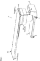
Fig. 1 ] is a perspective view illustrating an outer configuration of one example of a medical treatment and surgical operation table. - [
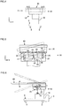
Fig. 2 ] is a diagram explaining an operation example of a table of the medical treatment and operation table in X- and Z-directions. - [
Fig. 3 ] is a diagram explaining an inclination example of the table of the medical treatment and surgical operation table in the X-direction. - [
Fig. 4 ] is a diagram explaining an operation example of the table of the medical treatment and surgical operation table in the Y-direction. - [
Fig. 5 ] is a diagram explaining an inclination example of the table of the medical treatment/ surgical operation table in the Y-direction. - [
Fig. 6 ] is a view showing a structure of an inclining mechanism of the table of the medical treatment and surgical operation table in the X-direction. - [
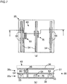
Fig. 7 ] is a structural view illustrating an arrangement example of a moving mechanism of a table in a horizontally moving portion in Y-direction and a table fixing/releasing mechanism, in whichFig. 7(a) is a plan view andFig. 7(b) is a sectional view taken along the line I-I ofFig. 7(a) . - [
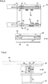
Fig. 8 ] is a structural view illustrating example of arrangement of a moving mechanism for moving the table of the horizontally movable portion in an X-direction of a table fixing/ releasing mechanism, in whichFig. 8(a) is a plan view andFig. 8(b) is a sectional view taken along the line II-II ofFig. 8(a) . - [
Fig. 9 ] is a schematic structural view illustrating a first fixing/ releasing mechanism. - [
Fig. 10 ] is a schematic structural view illustrating a second fixing/releasing mechanism, in whichFig. 10(a) is an illustration showing a released state andFig. 10(b) is an illustration showing a fixed state. Mode for embodying The Invention - Hereunder, an embodiment for carrying out the present invention will be explained with reference to the accompanying drawings. For the sake of convenience, it is to be noted that, with reference to
Fig. 1 , a left-right direction is mentioned as an X-direction and a front-back direction of the medical treatment table, a vertical direction is mentioned as a Z-direction and a vertical direction of the medical treatment table, and a front/depth direction is mentioned as a Y-direction and a left-right direction of the medical treatment table. Further, the medical treatment table in the present embodiment is a table that is usable for a doctor in a field of the endovascular treatment using an X-ray apparatus. However, the present embodiment is not limited to such field and the table may be of course usable for a general surgical operation table or a general medical treatment table. - As shown in
Fig. 1 , a medical treatment and surgical operation table 2 of the present embodiment is provided with abase 5, atable operation unit 10 mounted on thebase 5, a table 40 mounted on thetable operation unit 10.Casters 6 may be equipped for lower four corners of thebase 5 as occasion demands, and according to the attaching of thesecasters 6, the medical treatment and surgical operation table 2 is freely movable on a floor. - A
case 3, in which a control device for electrically controlling the medical treatment and surgical operation table 2 and other members or like are accommodated, is mounted to thebase 5. Thecase 3 is provided, on its surface, with acover member 3a to be openable and closable, and a button or other parts, not shown, for electrically controlling the medical treatment and surgical operation table are optionally arranged inside thecover member 3a. - The table 40 is made of a carbon or like material capable of transmitting an X-ray and composed of one sheet plate-like member having a size by which a patient laying on the table can be supported. The table 40 is provided with a
frame 42 covering the side portion of a rear end of the table so as to support the table 40 in the horizontal direction. The table 40 has a structure, except the rear end portion, not damaged by the transmission of the X-ray in its perpendicular direction. Further, for example, a head portion of a patient is placed on the front portion of the table 40 and a leg portion of the patient is placed on the rear portion thereof. - The
table operation unit 10 is, as shown inFigs. 1 to 4 , disposed on a lower portion of thetable frame 42 and is provided with a plurality of operating mechanisms for performing various operations of the table 40. The operating mechanisms include anelevating mechanism 15 for vertically elevating the table 40, aninclining mechanism 25 for freely inclining the table 40, and a horizontallymovable mechanism 35 for moving the table in the horizontal direction with hands. - The
elevating mechanism 15 is arranged, as shown inFig. 2 , above thebase 5 to be expanded or contracted in the perpendicular direction, and as shown with arrow, to be adjustable in height level of the table in accordance with a height of a doctor. The incliningmechanism 25 is positioned above theelevating mechanism 15 and coupled with the table via a laterally turningshaft 26 and a longitudinally turningshaft 27 in a manner such that the table 40 can be laterally turned with the laterally turningshaft 26 being fulcrum while longitudinally turned with the longitudinally turningshaft 27 being fulcrum as shown inFig. 6 . Thus, the inclination of the table 40 can be adjusted by a doctor to thereby change a posture of the patient at which the doctor can easily treat the patient. Furthermore, the horizontallymovable mechanism 35 is positioned, as shown inFigs. 2 ,4 ,7 and8 , above theinclining mechanism 25 so as to freely slide the table with hands in the longitudinally and laterally horizontal direction to thereby move the position of the patient, i.e., table 40, in the horizontally all directions thereof. - The
elevating mechanism 15 is provided, as shown inFig. 2 with dotted line, with arod member 16 including a plurality ofrods 16a and 16b combined to be expanded and contracted in the perpendicular direction between thebase 5 and theinclining mechanism 25, and ahydraulic cylinder assembly 17 which slides the rod 16b in the vertical direction with respect to therods 16a. Therod member 16 and thehydraulic cylinder assembly 17 are entirely covered by a verticallyexpandable cover 18. When thehydraulic cylinder assembly 17 is driven, therod member 16 combined with therods 16a and 16b is expanded or contracted to thereby vertically elevate the table 40 to a desired height level. - The inclining
mechanism 25 is arranged, as shown inFigs. 5 and 6 , between theelevating mechanism 15 and the horizontallymovable mechanism 35 and provided with ahousing 28 by which the laterally turningshaft 26 and the longitudinally turningshaft 27 are held. Thehousing 28 has a box-shaped structure substantially in form of rectangular parallelepiped shape, and is coupled with abracket 85 upwardly standing from an upper end of the elevatingmechanism 15 via the laterally turningshaft 26. On the other hand, the longitudinally turningshaft 27 is provided on each side of the horizontally arrangedhousing 28 perpendicular to the laterally turningshaft 26 so as to project outward in the horizontal direction, and the tip end of the longitudinally turningshafts 27 are coupled with left and right (lateral) downwardly directedbrackets 29 projecting perpendicularly from the lower end of the horizontallymovable mechanism 35. - Furthermore, a
pin 31 is provided at a perpendicularly upper portion of the laterally turningshaft 26 in a manner held by thehousing 28, and a rod is connected to thepin 31 provided withhydraulic cylinder assemblies shaft 26. When cylinders of the respective cylinder assemblies 32 and 33 are reciprocated in directions reverse to each other, the rod pushes thepin 31 to thereby incline the table 40 in the lateral direction with a predetermined inclination with the laterally turning shaft being the fulcrum. - Further, as shown in
Fig. 6 , in front of thelongitudinally turning shaft 27, ahydraulic cylinder assembly 34 is arranged so as to expand or contract arod 34a in the perpendicular direction between the elevatingmechanism 15 and the horizontallymovable mechanism 35. When thehydraulic cylinder assembly 34 is driven, the length of therod 34a is expanded or contracted so as to incline the front and rear portions of the table 40 at the predetermined inclination with thelongitudinally turning shaft 27 being the fulcrum. - Furthermore, as shown in
Figs. 7 and8 , the horizontallymovable mechanism 35 is provided with alower side housing 35a arranged above theinclining mechanism 25 and anupper side housing 35b attached to an upper end portion of the lower side housing to be slidable and coupled with the table 40. Further, anupper support member 36, acentral support member 37 and alower support member 38 are provided respectively with the upper end portion of the upper side hosing 35b, a boundary portion between theupper side housing 35b and thelower side housing 35a, and the lower end portion of thelower side housing 35a with predetermined intervals, respectively, in the horizontal direction. - As shown in
Fig. 8 , twovertical guide rails 51 arranged in parallel are attached to the upper support member (bracket) 36 so as to extend in the X-direction on both lateral side end portions within theupper side housing 35b. A plurality of guiderail support members 52 supporting thevertical guide rails 51 to be slidable on both lateral sides are mounted with equal interval to thecenter support member 37. The guide rails 51 are freely movable in the X-direction, and according to the movement of the guide rails 51, theupper support member 36 and the table 40 becomes movable in the front-and-rear (longitudinal) direction. - On the other hand, as shown in
Fig. 7 , threehorizontal guide rails 54 arranged in parallel with equal interval are attached to thecenter support member 37 so as to extend in the lateral direction within thelower side housing 35a. A plurality of guiderail support members 55 supporting thehorizontal guide rails 54 to be slidable on both lateral sides are mounted with equal interval to thelower support member 38. The guide rails 54 are freely movable in the Y-direction, and according to the movement of the guide rails 51, theupper support member 36 and the table 40 becomes movable in the lateral direction. - According to the horizontally
movable mechanism 35 having the structure mentioned above, when an operator manually handles the table 40 in the longitudinal or lateral direction, thevertical guide rails 51 orhorizontal guide rails 54 are moved within therespective support members - Furthermore, the medical treatment and surgical operation table 2 according to the present embodiment is provided with, as shown in
Fig. 7(a) , a fixing/releasingmechanism 60 for fixing the table 40 that is movable in the horizontal direction and releasing such fixing of the table for allowing the table to be movable. The fixing/releasingmechanism 60 includes a first fixing/releasingmechanism 65 and a second fixing/releasingmechanism 75 having different fixing force for fixing the movement of the table by the operator, in which the first fixing/ releasingmechanism 65 has a fixing force larger than that of the second fixing/releasingmechanism 75 and has a fixing/releasing time (i.e., speed) slower than that of the second fixing/ releasing mechanism. - More specifically, the first fixing/releasing
mechanism 65 is one for fixing the movement of the table by utilizing magnetic force, and as shown inFig. 9 , includes aniron plate 66 attached to theupper support member 36 and having a magnetic force, apermanent magnet 68 pushed against asupport member 67 attached to thelower support member 38 with a spring force, acoil 69 arranged around the permanent magnet, and acover member 70 arranged apart from the iron plate so as to cover thepermanent magnet 68 and thecoil 69. The movement of the table 40 is fixed by adsorbing the permanent magnet 68 (cover member 70) arranged apart from theiron plate 66. Further, on the other hand, by applying current to thecoil 69, the magnetic force of thepermanent magnet 68 is neutralized and thepermanent magnet 68 is separated from theiron plate 66 to thereby release the fixing of the table to be movable. - Further, although the first fixing/releasing
mechanism 65 is merely composed of a permanent magnet and a coil, it may be composed of a mechanism generally called an electromagnet. - On the other hand, the second fixing/releasing
mechanism 75 includes, as shown inFig. 10 , amotor 77 including arotating shaft 76, acam 78 that is moved by the rotation of therotating shaft 76, apin 79 engaging thecam 78, and apush member 80 for pushing at least one side surface of the guide rails 51 and 54 arranged between thecam 78 and the guide rails 51 and 54. According to such structure, when the motor is driven, the rotatingshaft 76 of themotor 77 is expanded or contracted to thereby move thecam 78, and hence, thepush member 80 pushes the one side surface of the guide rails 51, 54 by thepin 79 engaged with theinclination surface 78a formed to thecam 78, thereby fixing the movement of the guide rails 51 and 54. On the other hand, since thecam 78 is moved to the original position by reverse rotation of the motor , the push member is separated from the side surfaces of the guide rails 51 and 54, so that the fixing of the guide rails 51 and 54 is released to be movable. - Further, when the table 40 is moved in the horizontal direction, it is required for the table 40 to be promptly fixed and/or for the fixed table to be promptly moved, and when the table 40 is inclined, it is required for the table to have high fixing force so as not to be moved. Therefore, in the present embodiment, it is desirable to use the first fixing/releasing
mechanism 65 as fixing/releasing means at the time of moving the table 40 in the horizontal direction, and also use the second fixing/ releasingmechanism 75 as table fixing means at the time of inclining the table 40. - Furthermore, as the second fixing/releasing mechanism, a hydraulic mechanism or pneumatic mechanism may be used instead of the motor so as to bring the
push member 80 into contact with the guide rails 51 and 54. - Next, an example of using the medical treatment and surgical operation table will be explained, and herein, the first and second fixing/releasing
mechanisms mechanism 65 is always fixed and released only at a time of operating the button for releasing. Further, the second fixing/releasingmechanism 75 of the present embodiment is controlled so that it is released at a time when the table 40 takes the horizontal position and automatically fixed only at a time when the table 40 is inclined. Moreover, the elevation and/or inclination control of the table 40 is performed by operating a predetermined button for elevation and/or inclination. - In the operation at an initial stage, as shown in
Fig. 1 , the table 40 is held to be horizontally. Then, when an operator operates a button for releasing, the table 40 becomes movable in the lateral and longitudinal directions to be moved in all the directions by the movement of the guide rails 51 and 54. On the contrary, when the operation of the button for releasing is stopped, the movement of the guide rails 51 and 54 fixed by the first fixing/releasingmechanism 65 is fixed, and hence, the table 40 becomes immovable. - Further, when it is required to further move the table 40, the fixing of the table 40 (i.e., fixing of the guide rails 51, 54) can be released by operating the button for releasing. Although the fixing force of the first fixing/releasing mechanism is weak, since the response is prompt, the fixing or releasing of the table 40 can be promptly performed, thus being convenient for the operator in use.
- Furthermore, in an occasion of using the table as surgical operation table, when the table is elevated or inclined, the elevation or inclination thereof can be done by operating a button for inclination. In the inclining position of the table 40, the movement of the guide rails 51 and 54 is fixed for the sake of safety so that the table 40 is not automatically moved by the second fixing/releasing
mechanism 75. In this time, the second fixing/releasingmechanism 75 is controlled so as not to be released even if the button for releasing is operated. - Although the second fixing/releasing
mechanism 75 has the reaction promptness is slower than that of the first fixing/releasingmechanism 65, since it has the fixing force higher than that of the first one, the table 40 is not moved during the inclining operation, thus being safeness. - As mentioned hereinabove, the medical treatment and surgical operation table of the present embodiment is provided with two fixing/releasing mechanisms having different fixing forces and reaction speeds for fixing or releasing the movement of the table 40 in the horizontal direction so as to be operated separately in accordance with requirement for use, and accordingly, the medical treatment and surgical operation table can be conveniently handled for the operator in use.
- It is further to be noted that the present embodiment is one example and the present invention is not limited thereto. For example, the table operation mechanisms of the present embodiment may be replaced with other generally known mechanisms. Moreover, even for the first fixing/releasing mechanism, it is important to includes with a plurality of fixing/releasing mechanisms having different fixing forces and reaction speeds, and hence, it may be possible to use other electric or mechanical mechanisms in place thereof. Furthermore, a plurality of fixing/releasing mechanisms having same fixing forces and reaction speeds may be provided, and in this case, only in a time when the table is horizontally moved, selective ones of the plural fixing/releasing mechanisms are operated. More specifically, for example, at a time when the horizontal movement of the table is fixed or released, the movement of the table is fixed by one or two fixing/releasing mechanisms of the plural ones, and on the other hand, at a time when the movement of the table in the inclining time is fixed or released, the movement of the table is fixed by all the fixing/releasing mechanisms. According to such operation manner, the fixing force can be controlled in different manners in the horizontal state and inclination state of the table 40.
-
- 2 --- medical treatment and surgical operation table
- 5 --- base
- 10 --- operation unit
- 40 --- table
- 65 --- first fixing/ releasing mechanism (fixing/ releasing means)
- 75 --- second fixing/releasing mechanism (another fixing/releasing means)
Claims (2)
- A medical treatment and surgical operation table (2) comprising:a table (40) which is formed of a material through which an X-ray transmits and on which a patient lays;an operation unit (10) that supports a lower side of one end portion of the table (40) and includes: an elevating mechanism (15) for vertically elevating the table (40), an inclining mechanism (25) for freely inclining the table (40), and a horizontally movable mechanism (35) for moving the table (40) in the horizontal direction, wherein the horizontally movable mechanism (35) comprises vertical guide rails (51) slidably supported by corresponding vertical guide rail support members (52), and horizontal guide rails (54) slidably supported by corresponding horizontal guide rail support members (54);a base (5) that supports the operation unit (10); andfixing/releasing means (60) configured to fix a movement of the table (40) or to release the fixing of the table (40), the fixing/releasing means (60) comprising a first fixing/releasing mechanism (65) and a second fixing/releasing mechanism (75),wherein the first fixing/releasing mechanism (65) comprises a permanent magnet (68) and a coil (69) arranged around the permanent magnet (68), wherein by applying a current to the coil (69), the magnetic force of the permanent magnet (68) is neutralized, thereby releasing the fixing of the table (40) to be movable, wherein the second fixing/releasing mechanism (75) comprises a motor (77) including a rotating shaft (76), a cam (78) movable by a rotation of the rotating shaft (76), a pin (79) engaged with an inclination surface (78a) of the cam (78), and a push member (80) for pushing at least one side surface of the guide rails (51, 54), wherein when the motor (77) is driven, the rotating shaft (76) of the motor (77) is expanded to thereby move the cam (78) and to thereby push the push member (80) against one side surface of the guide rails (51, 54) by the pin (79), thereby fixing the movement of the guide rails (51, 54), and when the cam (78) is moved to the original position by reverse rotation of the motor (77), the push member (80) is separated from the side surface of the guide rails (51, 54), thereby releasing the fixing of the table (40),wherein the second fixing/releasing mechanism (75) has a fixing force for fixing the movement of the table (40) that is larger than that of the first fixing/releasing mechanism (65),wherein when the table (40) is in a horizontal position, the table (40) is held fixed by the first fixing/releasing mechanism (65) and is released only at a time of operating a button for releasing, wherein the second fixing/releasing mechanism (75) is controlled so that it is released at a time when the table (40) takes the horizontal position and is automatically fixed only at a time when the table (40) is inclined.
- The medical treatment and surgical operation table (2) according to claim 1, wherein the first fixing/releasing mechanism (65) has a reaction speed for fixing the movement of the table (40) or releasing the fixing of the table (40) faster than that of the second fixing/releasing mechanism (75).
Applications Claiming Priority (2)
| Application Number | Priority Date | Filing Date | Title |
|---|---|---|---|
| JP2011276378A JP5473084B2 (en) | 2011-12-16 | 2011-12-16 | Medical treatment and operating table |
| PCT/JP2012/082470 WO2013089220A1 (en) | 2011-12-16 | 2012-12-14 | Medical examination-cum-surgery table |
Publications (3)
| Publication Number | Publication Date |
|---|---|
| EP2792304A1 EP2792304A1 (en) | 2014-10-22 |
| EP2792304A4 EP2792304A4 (en) | 2015-08-12 |
| EP2792304B1 true EP2792304B1 (en) | 2020-04-08 |
Family
ID=48612659
Family Applications (1)
| Application Number | Title | Priority Date | Filing Date |
|---|---|---|---|
| EP12858004.0A Active EP2792304B1 (en) | 2011-12-16 | 2012-12-14 | Medical examination-cum-surgery table |
Country Status (5)
| Country | Link |
|---|---|
| US (1) | US20150000038A1 (en) |
| EP (1) | EP2792304B1 (en) |
| JP (1) | JP5473084B2 (en) |
| CN (1) | CN104010576B (en) |
| WO (1) | WO2013089220A1 (en) |
Families Citing this family (20)
| Publication number | Priority date | Publication date | Assignee | Title |
|---|---|---|---|---|
| US9597043B1 (en) * | 2012-05-31 | 2017-03-21 | Dartmouth-Hitchcock Clinic | System and method for supporting a patient for imagery during surgery |
| CN103610557A (en) * | 2013-12-05 | 2014-03-05 | 玉林市科邦技术服务有限公司 | Plane moving device of operating table top |
| CN103610552A (en) * | 2013-12-05 | 2014-03-05 | 玉林市科邦技术服务有限公司 | Diagnosis and treatment operating table for endoscope retrograde cholangiopancreatography |
| US10716521B2 (en) * | 2014-06-26 | 2020-07-21 | Frencken Europe B.V. | Patient support system and levelling system for such a patient support system |
| CN105769497B (en) * | 2016-05-05 | 2017-11-03 | 杨琨 | One kind intervention perspective wheeled litter |
| DE102016113508B4 (en) * | 2016-07-21 | 2019-01-17 | Irina Gewinner | Operating table for angiographic procedures under X-ray control |
| JP6216858B1 (en) | 2016-10-26 | 2017-10-18 | 株式会社メディカロイド | Robotic operating table |
| US11602474B2 (en) | 2016-11-28 | 2023-03-14 | Verb Surgical Inc. | Surgical table base with high stiffness and adjustable support members with force feedback |
| DE102016125800A1 (en) * | 2016-12-28 | 2018-06-28 | MAQUET GmbH | Operating table column with stabilization guide |
| JP6568884B2 (en) | 2017-02-28 | 2019-08-28 | 株式会社メディカロイド | Robot operating table and operation device for robot operating table |
| JP6784610B2 (en) | 2017-02-28 | 2020-11-11 | 株式会社メディカロイド | Operating table operation device and operating table |
| JP6487954B2 (en) | 2017-02-28 | 2019-03-20 | 株式会社メディカロイド | Robot operating table and operation device for robot operating table |
| JP6488033B2 (en) | 2017-02-28 | 2019-03-20 | 株式会社メディカロイド | Robotic operating table |
| JP6599913B2 (en) * | 2017-02-28 | 2019-10-30 | 株式会社メディカロイド | Robot operating table operating device |
| JP6800058B2 (en) | 2017-03-23 | 2020-12-16 | 株式会社メディカロイド | How to move the patient placement table |
| EP3668471A4 (en) * | 2017-08-16 | 2021-05-05 | Covidien LP | Operating table for robotic surgical systems |
| CN108505271B (en) * | 2018-04-10 | 2020-09-08 | 佛山市艾温特智能科技有限公司 | Accomodate convenient portable washing machine |
| US10517554B1 (en) * | 2018-09-07 | 2019-12-31 | Shimadzu Corporation | X-ray fluoroscopic imaging apparatus |
| KR102624013B1 (en) * | 2021-10-05 | 2024-01-12 | (주)씨비에이치 | Carring device equipped with a medical table |
| KR20240036208A (en) * | 2022-09-13 | 2024-03-20 | (주)씨비에이치 | Carring device equipped with a medical table |
Family Cites Families (25)
| Publication number | Priority date | Publication date | Assignee | Title |
|---|---|---|---|---|
| US4761000A (en) * | 1987-04-07 | 1988-08-02 | American Sterilizer Company | Surgical table having horizontally displaceable tabletop |
| JPH0242275Y2 (en) * | 1987-05-18 | 1990-11-09 | ||
| BE1007673A3 (en) * | 1993-10-27 | 1995-09-12 | Philips Electronics Nv | Medical device having a moveable patient table. |
| US5467850A (en) * | 1993-12-16 | 1995-11-21 | Otis Elevator Company | Permanent magnet, magnetodynamic safety brake for elevators and the like |
| JPH1066714A (en) * | 1996-08-28 | 1998-03-10 | Mizuho Ika Kogyo Kk | Operating table |
| EP0923922A3 (en) * | 1997-12-18 | 2000-02-09 | Stille-Beta, Inc. | Improved operating room table |
| DE19955119B4 (en) * | 1999-11-16 | 2009-12-24 | Maquet Gmbh & Co. Kg | Patient support plate for a medical examination table |
| JP4678999B2 (en) * | 2001-07-27 | 2011-04-27 | 株式会社東芝 | X-ray diagnostic equipment |
| EP1297812A1 (en) * | 2001-10-01 | 2003-04-02 | Hoerbiger Micro Fluid GmbH | Adjustable patient-supporting device |
| JP2004073616A (en) | 2002-08-21 | 2004-03-11 | Mizuho Co Ltd | Operation table |
| US7028356B2 (en) * | 2002-11-26 | 2006-04-18 | Ge Medical Systems Global Technology Company, Llc | Multiconfiguration braking system |
| US6986179B2 (en) * | 2002-11-26 | 2006-01-17 | Ge Medical Systems Global Technology Company, Llc | Grouted tilting patient positioning table for vascular applications |
| US7125167B2 (en) * | 2003-03-04 | 2006-10-24 | Ge Medical Systems Global Technology Company, Llc | Method and apparatus for tilting in a patient positioning system |
| JP4434701B2 (en) * | 2003-11-21 | 2010-03-17 | 株式会社東芝 | Bed equipment |
| US7103931B2 (en) * | 2004-08-28 | 2006-09-12 | General Electric Company | Table drive system for medical imaging apparatus |
| US7234179B2 (en) * | 2004-12-29 | 2007-06-26 | Chun-Fa Shaw | Rocking bed |
| US20060260051A1 (en) * | 2005-05-17 | 2006-11-23 | Ohad Paz | Patient support apparatus |
| JP4810182B2 (en) * | 2005-10-17 | 2011-11-09 | キヤノン株式会社 | Radiography equipment |
| DE102005055653A1 (en) * | 2005-11-22 | 2007-05-24 | Siemens Ag | X-ray diagnosing device for examination object, has control device effectively connected with position determining device and braking device that is activated based on position of components relative to stop position by control device |
| DE102007059520B4 (en) * | 2007-12-11 | 2016-06-16 | Siemens Healthcare Gmbh | Medical table for storing patients and related procedures |
| DE102008025941B4 (en) * | 2008-05-30 | 2017-02-02 | Siemens Healthcare Gmbh | braking device |
| JP2010099162A (en) * | 2008-10-22 | 2010-05-06 | Shimadzu Corp | X-ray imaging apparatus |
| JP5623051B2 (en) * | 2009-09-29 | 2014-11-12 | 株式会社東芝 | Bed apparatus and medical image diagnostic apparatus |
| DE102010023033A1 (en) * | 2010-06-08 | 2011-12-08 | Siemens Aktiengesellschaft | Medical table with a couch board |
| KR101361473B1 (en) * | 2012-09-06 | 2014-02-11 | 삼성전자주식회사 | Device for controlling stroke of collision switch and medical diagnosis apparatus employing the same |
-
2011
- 2011-12-16 JP JP2011276378A patent/JP5473084B2/en active Active
-
2012
- 2012-12-14 EP EP12858004.0A patent/EP2792304B1/en active Active
- 2012-12-14 US US14/365,444 patent/US20150000038A1/en not_active Abandoned
- 2012-12-14 WO PCT/JP2012/082470 patent/WO2013089220A1/en active Application Filing
- 2012-12-14 CN CN201280062126.0A patent/CN104010576B/en active Active
Non-Patent Citations (1)
| Title |
|---|
| None * |
Also Published As
| Publication number | Publication date |
|---|---|
| EP2792304A4 (en) | 2015-08-12 |
| CN104010576A (en) | 2014-08-27 |
| JP5473084B2 (en) | 2014-04-16 |
| CN104010576B (en) | 2017-03-22 |
| WO2013089220A1 (en) | 2013-06-20 |
| US20150000038A1 (en) | 2015-01-01 |
| EP2792304A1 (en) | 2014-10-22 |
| JP2013126454A (en) | 2013-06-27 |
Similar Documents
| Publication | Publication Date | Title |
|---|---|---|
| EP2792304B1 (en) | Medical examination-cum-surgery table | |
| US6322251B1 (en) | Operating table system | |
| US6385481B2 (en) | Diagnostic system with a chair and table movable on rails provided on vertical magnets thereof | |
| JP5661603B2 (en) | Cassette holder and medical bed | |
| JP2022517344A (en) | Equipment for transporting biomedical devices | |
| EP3195842B1 (en) | Surgical table | |
| JP5501468B2 (en) | Mobile element or unit | |
| EP3616665A1 (en) | Patient transfer system | |
| WO2019204000A1 (en) | Surgical robotic systems | |
| CN210354688U (en) | Magnetic resonance guiding and positioning device | |
| KR101589598B1 (en) | Patient Transport Apparatus | |
| JP6294146B2 (en) | Medical table | |
| KR20230084728A (en) | Operating Table comprising Floating Function | |
| KR101409715B1 (en) | Ceiling suspended x-ray imaging apparatus | |
| JP2015058117A (en) | Mobile x-ray diagnostic apparatus | |
| JP6362852B2 (en) | Mobile X-ray diagnostic device | |
| JP4709655B2 (en) | X-ray diagnostic equipment | |
| WO2019097594A1 (en) | Radiation photographing device | |
| JP2000354638A (en) | Treatment table of radiotherapy apparatus | |
| KR102511036B1 (en) | Treatment tool control device | |
| JP2009207835A (en) | Radiography apparatus | |
| JP4041754B2 (en) | Magnetic resonance imaging system | |
| JP3148807U (en) | X-ray fluoroscopic equipment | |
| JP2003199743A (en) | X-ray equipment | |
| JP2022173654A (en) | Motor-driven optical base and inspection system |
Legal Events
| Date | Code | Title | Description |
|---|---|---|---|
| PUAI | Public reference made under article 153(3) epc to a published international application that has entered the european phase |
Free format text: ORIGINAL CODE: 0009012 |
|
| 17P | Request for examination filed |
Effective date: 20140613 |
|
| AK | Designated contracting states |
Kind code of ref document: A1 Designated state(s): AL AT BE BG CH CY CZ DE DK EE ES FI FR GB GR HR HU IE IS IT LI LT LU LV MC MK MT NL NO PL PT RO RS SE SI SK SM TR |
|
| DAX | Request for extension of the european patent (deleted) | ||
| RA4 | Supplementary search report drawn up and despatched (corrected) |
Effective date: 20150713 |
|
| RIC1 | Information provided on ipc code assigned before grant |
Ipc: A61G 13/10 20060101ALI20150707BHEP Ipc: A61B 6/04 20060101AFI20150707BHEP |
|
| STAA | Information on the status of an ep patent application or granted ep patent |
Free format text: STATUS: EXAMINATION IS IN PROGRESS |
|
| 17Q | First examination report despatched |
Effective date: 20180724 |
|
| GRAP | Despatch of communication of intention to grant a patent |
Free format text: ORIGINAL CODE: EPIDOSNIGR1 |
|
| STAA | Information on the status of an ep patent application or granted ep patent |
Free format text: STATUS: GRANT OF PATENT IS INTENDED |
|
| INTG | Intention to grant announced |
Effective date: 20190405 |
|
| GRAJ | Information related to disapproval of communication of intention to grant by the applicant or resumption of examination proceedings by the epo deleted |
Free format text: ORIGINAL CODE: EPIDOSDIGR1 |
|
| STAA | Information on the status of an ep patent application or granted ep patent |
Free format text: STATUS: EXAMINATION IS IN PROGRESS |
|
| INTC | Intention to grant announced (deleted) | ||
| GRAP | Despatch of communication of intention to grant a patent |
Free format text: ORIGINAL CODE: EPIDOSNIGR1 |
|
| STAA | Information on the status of an ep patent application or granted ep patent |
Free format text: STATUS: GRANT OF PATENT IS INTENDED |
|
| INTG | Intention to grant announced |
Effective date: 20191122 |
|
| RIN1 | Information on inventor provided before grant (corrected) |
Inventor name: OBI, TAKUYA |
|
| GRAS | Grant fee paid |
Free format text: ORIGINAL CODE: EPIDOSNIGR3 |
|
| GRAA | (expected) grant |
Free format text: ORIGINAL CODE: 0009210 |
|
| STAA | Information on the status of an ep patent application or granted ep patent |
Free format text: STATUS: THE PATENT HAS BEEN GRANTED |
|
| AK | Designated contracting states |
Kind code of ref document: B1 Designated state(s): AL AT BE BG CH CY CZ DE DK EE ES FI FR GB GR HR HU IE IS IT LI LT LU LV MC MK MT NL NO PL PT RO RS SE SI SK SM TR |
|
| REG | Reference to a national code |
Ref country code: GB Ref legal event code: FG4D |
|
| REG | Reference to a national code |
Ref country code: AT Ref legal event code: REF Ref document number: 1253265 Country of ref document: AT Kind code of ref document: T Effective date: 20200415 Ref country code: CH Ref legal event code: EP |
|
| REG | Reference to a national code |
Ref country code: IE Ref legal event code: FG4D |
|
| REG | Reference to a national code |
Ref country code: DE Ref legal event code: R096 Ref document number: 602012069202 Country of ref document: DE |
|
| REG | Reference to a national code |
Ref country code: NL Ref legal event code: MP Effective date: 20200408 |
|
| REG | Reference to a national code |
Ref country code: LT Ref legal event code: MG4D |
|
| PG25 | Lapsed in a contracting state [announced via postgrant information from national office to epo] |
Ref country code: NL Free format text: LAPSE BECAUSE OF FAILURE TO SUBMIT A TRANSLATION OF THE DESCRIPTION OR TO PAY THE FEE WITHIN THE PRESCRIBED TIME-LIMIT Effective date: 20200408 Ref country code: PT Free format text: LAPSE BECAUSE OF FAILURE TO SUBMIT A TRANSLATION OF THE DESCRIPTION OR TO PAY THE FEE WITHIN THE PRESCRIBED TIME-LIMIT Effective date: 20200817 Ref country code: LT Free format text: LAPSE BECAUSE OF FAILURE TO SUBMIT A TRANSLATION OF THE DESCRIPTION OR TO PAY THE FEE WITHIN THE PRESCRIBED TIME-LIMIT Effective date: 20200408 Ref country code: IS Free format text: LAPSE BECAUSE OF FAILURE TO SUBMIT A TRANSLATION OF THE DESCRIPTION OR TO PAY THE FEE WITHIN THE PRESCRIBED TIME-LIMIT Effective date: 20200808 Ref country code: SE Free format text: LAPSE BECAUSE OF FAILURE TO SUBMIT A TRANSLATION OF THE DESCRIPTION OR TO PAY THE FEE WITHIN THE PRESCRIBED TIME-LIMIT Effective date: 20200408 Ref country code: NO Free format text: LAPSE BECAUSE OF FAILURE TO SUBMIT A TRANSLATION OF THE DESCRIPTION OR TO PAY THE FEE WITHIN THE PRESCRIBED TIME-LIMIT Effective date: 20200708 Ref country code: GR Free format text: LAPSE BECAUSE OF FAILURE TO SUBMIT A TRANSLATION OF THE DESCRIPTION OR TO PAY THE FEE WITHIN THE PRESCRIBED TIME-LIMIT Effective date: 20200709 Ref country code: FI Free format text: LAPSE BECAUSE OF FAILURE TO SUBMIT A TRANSLATION OF THE DESCRIPTION OR TO PAY THE FEE WITHIN THE PRESCRIBED TIME-LIMIT Effective date: 20200408 |
|
| REG | Reference to a national code |
Ref country code: AT Ref legal event code: MK05 Ref document number: 1253265 Country of ref document: AT Kind code of ref document: T Effective date: 20200408 |
|
| PG25 | Lapsed in a contracting state [announced via postgrant information from national office to epo] |
Ref country code: HR Free format text: LAPSE BECAUSE OF FAILURE TO SUBMIT A TRANSLATION OF THE DESCRIPTION OR TO PAY THE FEE WITHIN THE PRESCRIBED TIME-LIMIT Effective date: 20200408 Ref country code: LV Free format text: LAPSE BECAUSE OF FAILURE TO SUBMIT A TRANSLATION OF THE DESCRIPTION OR TO PAY THE FEE WITHIN THE PRESCRIBED TIME-LIMIT Effective date: 20200408 Ref country code: RS Free format text: LAPSE BECAUSE OF FAILURE TO SUBMIT A TRANSLATION OF THE DESCRIPTION OR TO PAY THE FEE WITHIN THE PRESCRIBED TIME-LIMIT Effective date: 20200408 Ref country code: BG Free format text: LAPSE BECAUSE OF FAILURE TO SUBMIT A TRANSLATION OF THE DESCRIPTION OR TO PAY THE FEE WITHIN THE PRESCRIBED TIME-LIMIT Effective date: 20200708 |
|
| PG25 | Lapsed in a contracting state [announced via postgrant information from national office to epo] |
Ref country code: AL Free format text: LAPSE BECAUSE OF FAILURE TO SUBMIT A TRANSLATION OF THE DESCRIPTION OR TO PAY THE FEE WITHIN THE PRESCRIBED TIME-LIMIT Effective date: 20200408 |
|
| REG | Reference to a national code |
Ref country code: DE Ref legal event code: R097 Ref document number: 602012069202 Country of ref document: DE |
|
| PG25 | Lapsed in a contracting state [announced via postgrant information from national office to epo] |
Ref country code: ES Free format text: LAPSE BECAUSE OF FAILURE TO SUBMIT A TRANSLATION OF THE DESCRIPTION OR TO PAY THE FEE WITHIN THE PRESCRIBED TIME-LIMIT Effective date: 20200408 Ref country code: CZ Free format text: LAPSE BECAUSE OF FAILURE TO SUBMIT A TRANSLATION OF THE DESCRIPTION OR TO PAY THE FEE WITHIN THE PRESCRIBED TIME-LIMIT Effective date: 20200408 Ref country code: RO Free format text: LAPSE BECAUSE OF FAILURE TO SUBMIT A TRANSLATION OF THE DESCRIPTION OR TO PAY THE FEE WITHIN THE PRESCRIBED TIME-LIMIT Effective date: 20200408 Ref country code: IT Free format text: LAPSE BECAUSE OF FAILURE TO SUBMIT A TRANSLATION OF THE DESCRIPTION OR TO PAY THE FEE WITHIN THE PRESCRIBED TIME-LIMIT Effective date: 20200408 Ref country code: DK Free format text: LAPSE BECAUSE OF FAILURE TO SUBMIT A TRANSLATION OF THE DESCRIPTION OR TO PAY THE FEE WITHIN THE PRESCRIBED TIME-LIMIT Effective date: 20200408 Ref country code: SM Free format text: LAPSE BECAUSE OF FAILURE TO SUBMIT A TRANSLATION OF THE DESCRIPTION OR TO PAY THE FEE WITHIN THE PRESCRIBED TIME-LIMIT Effective date: 20200408 Ref country code: AT Free format text: LAPSE BECAUSE OF FAILURE TO SUBMIT A TRANSLATION OF THE DESCRIPTION OR TO PAY THE FEE WITHIN THE PRESCRIBED TIME-LIMIT Effective date: 20200408 Ref country code: EE Free format text: LAPSE BECAUSE OF FAILURE TO SUBMIT A TRANSLATION OF THE DESCRIPTION OR TO PAY THE FEE WITHIN THE PRESCRIBED TIME-LIMIT Effective date: 20200408 |
|
| PLBE | No opposition filed within time limit |
Free format text: ORIGINAL CODE: 0009261 |
|
| STAA | Information on the status of an ep patent application or granted ep patent |
Free format text: STATUS: NO OPPOSITION FILED WITHIN TIME LIMIT |
|
| PG25 | Lapsed in a contracting state [announced via postgrant information from national office to epo] |
Ref country code: SK Free format text: LAPSE BECAUSE OF FAILURE TO SUBMIT A TRANSLATION OF THE DESCRIPTION OR TO PAY THE FEE WITHIN THE PRESCRIBED TIME-LIMIT Effective date: 20200408 Ref country code: PL Free format text: LAPSE BECAUSE OF FAILURE TO SUBMIT A TRANSLATION OF THE DESCRIPTION OR TO PAY THE FEE WITHIN THE PRESCRIBED TIME-LIMIT Effective date: 20200408 |
|
| 26N | No opposition filed |
Effective date: 20210112 |
|
| PG25 | Lapsed in a contracting state [announced via postgrant information from national office to epo] |
Ref country code: SI Free format text: LAPSE BECAUSE OF FAILURE TO SUBMIT A TRANSLATION OF THE DESCRIPTION OR TO PAY THE FEE WITHIN THE PRESCRIBED TIME-LIMIT Effective date: 20200408 |
|
| REG | Reference to a national code |
Ref country code: CH Ref legal event code: PL |
|
| PG25 | Lapsed in a contracting state [announced via postgrant information from national office to epo] |
Ref country code: MC Free format text: LAPSE BECAUSE OF FAILURE TO SUBMIT A TRANSLATION OF THE DESCRIPTION OR TO PAY THE FEE WITHIN THE PRESCRIBED TIME-LIMIT Effective date: 20200408 |
|
| REG | Reference to a national code |
Ref country code: BE Ref legal event code: MM Effective date: 20201231 |
|
| PG25 | Lapsed in a contracting state [announced via postgrant information from national office to epo] |
Ref country code: LU Free format text: LAPSE BECAUSE OF NON-PAYMENT OF DUE FEES Effective date: 20201214 Ref country code: IE Free format text: LAPSE BECAUSE OF NON-PAYMENT OF DUE FEES Effective date: 20201214 |
|
| PG25 | Lapsed in a contracting state [announced via postgrant information from national office to epo] |
Ref country code: LI Free format text: LAPSE BECAUSE OF NON-PAYMENT OF DUE FEES Effective date: 20201231 Ref country code: CH Free format text: LAPSE BECAUSE OF NON-PAYMENT OF DUE FEES Effective date: 20201231 |
|
| PG25 | Lapsed in a contracting state [announced via postgrant information from national office to epo] |
Ref country code: TR Free format text: LAPSE BECAUSE OF FAILURE TO SUBMIT A TRANSLATION OF THE DESCRIPTION OR TO PAY THE FEE WITHIN THE PRESCRIBED TIME-LIMIT Effective date: 20200408 Ref country code: MT Free format text: LAPSE BECAUSE OF FAILURE TO SUBMIT A TRANSLATION OF THE DESCRIPTION OR TO PAY THE FEE WITHIN THE PRESCRIBED TIME-LIMIT Effective date: 20200408 Ref country code: CY Free format text: LAPSE BECAUSE OF FAILURE TO SUBMIT A TRANSLATION OF THE DESCRIPTION OR TO PAY THE FEE WITHIN THE PRESCRIBED TIME-LIMIT Effective date: 20200408 |
|
| PG25 | Lapsed in a contracting state [announced via postgrant information from national office to epo] |
Ref country code: MK Free format text: LAPSE BECAUSE OF FAILURE TO SUBMIT A TRANSLATION OF THE DESCRIPTION OR TO PAY THE FEE WITHIN THE PRESCRIBED TIME-LIMIT Effective date: 20200408 |
|
| PG25 | Lapsed in a contracting state [announced via postgrant information from national office to epo] |
Ref country code: BE Free format text: LAPSE BECAUSE OF NON-PAYMENT OF DUE FEES Effective date: 20201231 |
|
| PGFP | Annual fee paid to national office [announced via postgrant information from national office to epo] |
Ref country code: GB Payment date: 20231220 Year of fee payment: 12 |
|
| PGFP | Annual fee paid to national office [announced via postgrant information from national office to epo] |
Ref country code: FR Payment date: 20231220 Year of fee payment: 12 Ref country code: DE Payment date: 20231117 Year of fee payment: 12 |