EP2792256A1 - Flavour cartridge and non-heating type flavour inhaler - Google Patents
Flavour cartridge and non-heating type flavour inhaler Download PDFInfo
- Publication number
- EP2792256A1 EP2792256A1 EP12866687.2A EP12866687A EP2792256A1 EP 2792256 A1 EP2792256 A1 EP 2792256A1 EP 12866687 A EP12866687 A EP 12866687A EP 2792256 A1 EP2792256 A1 EP 2792256A1
- Authority
- EP
- European Patent Office
- Prior art keywords
- flavour
- cartridge
- pouch
- casing
- holder
- Prior art date
- Legal status (The legal status is an assumption and is not a legal conclusion. Google has not performed a legal analysis and makes no representation as to the accuracy of the status listed.)
- Granted
Links
Images




Classifications
-
- A—HUMAN NECESSITIES
- A61—MEDICAL OR VETERINARY SCIENCE; HYGIENE
- A61M—DEVICES FOR INTRODUCING MEDIA INTO, OR ONTO, THE BODY; DEVICES FOR TRANSDUCING BODY MEDIA OR FOR TAKING MEDIA FROM THE BODY; DEVICES FOR PRODUCING OR ENDING SLEEP OR STUPOR
- A61M15/00—Inhalators
- A61M15/06—Inhaling appliances shaped like cigars, cigarettes or pipes
-
- A—HUMAN NECESSITIES
- A24—TOBACCO; CIGARS; CIGARETTES; SIMULATED SMOKING DEVICES; SMOKERS' REQUISITES
- A24F—SMOKERS' REQUISITES; MATCH BOXES; SIMULATED SMOKING DEVICES
- A24F42/00—Simulated smoking devices other than electrically operated; Component parts thereof; Manufacture or testing thereof
- A24F42/20—Devices without heating means
-
- A—HUMAN NECESSITIES
- A24—TOBACCO; CIGARS; CIGARETTES; SIMULATED SMOKING DEVICES; SMOKERS' REQUISITES
- A24F—SMOKERS' REQUISITES; MATCH BOXES; SIMULATED SMOKING DEVICES
- A24F42/00—Simulated smoking devices other than electrically operated; Component parts thereof; Manufacture or testing thereof
- A24F42/60—Constructional details
-
- A—HUMAN NECESSITIES
- A61—MEDICAL OR VETERINARY SCIENCE; HYGIENE
- A61M—DEVICES FOR INTRODUCING MEDIA INTO, OR ONTO, THE BODY; DEVICES FOR TRANSDUCING BODY MEDIA OR FOR TAKING MEDIA FROM THE BODY; DEVICES FOR PRODUCING OR ENDING SLEEP OR STUPOR
- A61M15/00—Inhalators
- A61M15/08—Inhaling devices inserted into the nose
-
- A—HUMAN NECESSITIES
- A61—MEDICAL OR VETERINARY SCIENCE; HYGIENE
- A61M—DEVICES FOR INTRODUCING MEDIA INTO, OR ONTO, THE BODY; DEVICES FOR TRANSDUCING BODY MEDIA OR FOR TAKING MEDIA FROM THE BODY; DEVICES FOR PRODUCING OR ENDING SLEEP OR STUPOR
- A61M2202/00—Special media to be introduced, removed or treated
- A61M2202/06—Solids
- A61M2202/064—Powder
-
- A—HUMAN NECESSITIES
- A61—MEDICAL OR VETERINARY SCIENCE; HYGIENE
- A61M—DEVICES FOR INTRODUCING MEDIA INTO, OR ONTO, THE BODY; DEVICES FOR TRANSDUCING BODY MEDIA OR FOR TAKING MEDIA FROM THE BODY; DEVICES FOR PRODUCING OR ENDING SLEEP OR STUPOR
- A61M2205/00—General characteristics of the apparatus
- A61M2205/60—General characteristics of the apparatus with identification means
- A61M2205/6045—General characteristics of the apparatus with identification means having complementary physical shapes for indexing or registration purposes
-
- A—HUMAN NECESSITIES
- A61—MEDICAL OR VETERINARY SCIENCE; HYGIENE
- A61M—DEVICES FOR INTRODUCING MEDIA INTO, OR ONTO, THE BODY; DEVICES FOR TRANSDUCING BODY MEDIA OR FOR TAKING MEDIA FROM THE BODY; DEVICES FOR PRODUCING OR ENDING SLEEP OR STUPOR
- A61M2207/00—Methods of manufacture, assembly or production
Definitions
- the present invention relates to a flavour cartridge and a non-heating type flavour inhaler which provide a flavour component to a user through inhalation without requiring ignition.
- This type of non-heating type flavour inhaler is disclosed in the following Patent Document 1, for example.
- This flavour inhaler in Patent Document 1 is provided with a holder and a flavour cartridge held in the holder.
- the holder includes an air inlet, a mouthpiece, and an air communication path connecting the air inlet and the mouthpiece, while the flavour cartridge is arranged so as to divide the air communication path to an upstream side portion and a downstream side portion in the holder.
- the flavour cartridge includes a rectangular frame and a flavour pouch held in the frame, and the flavour pouch has a granular material emitting a flavour component and a permeable sheet wrapping the granular material, for example.
- flavour inhaler when the user inhales through the mouthpiece, an air flow passing through the flavour pouch and then, going toward the mouthpiece is generated in the air communication path.
- the flavour component emitted from the granular material in the flavour pouch is carried on the above described air flow into the oral cavity of the user and provides the flavour component to the user.
- Patent Document 1 International Publication No. 2010/095660 ( WO 2010/095660 )
- An object of the present invention is to provide a flavour cartridge which can efficiently deliver the flavour component emitted from the granular material and a non-heating type flavour inhaler provided with the flavour cartridge with a simple structure.
- flavour cartridge of the present invention comprises:
- an air flowing into the casing from the ventilation port reaches the internal chamber through the flavour pouch and generates an air flow flowing out from the internal chamber through the connection port.
- Such air flow does not bypass the flavour pouch but reliably passes through the flavour pouch and can efficiently contain the flavour component emitted from the granular material. Therefore, if a user can inhale the air flowing out of the connection port, the user can taste the rich flavour component.
- a space between the first wall and the sealing step is smaller than a thickness of the flavour pouch in a non-load state, and the first wall and the sealing step can maintain the flavour pouch in the compressed state in cooperation with each other.
- the support preferably further includes an abutting element protruding from an inner surface of the second wall and abutting on a surface of the flavour pouch exposed to the internal chamber. More preferably, a top end of the abutting element is substantially positioned in a plane including the sealing step or slightly protrudes from the plane toward the first wall side.
- the abutting element is a rib extending along the longitudinal axis of the casing or includes a plurality of bosses arranged at intervals from each other along the longitudinal axis.
- the above abutting element prevents movement of the granular material in the flavour pouch and maintains density of the granular material uniformly over the whole region of the flavour pouch.
- the flavour pouch is a pillow-packaged product having a traverse seal band at both ends thereof, respectively, the traverse seal bands are preferably folded. Such folding of the traverse seal bands reduces a size of the flavour pouch, and size reduction of the flavour pouch is made possible.
- the granular material can contain tobacco granules emitting a flavour component specific to tobacco.
- the present invention provides a non-heating type flavour inhaler, and the flavour inhaler comprises:
- flavour inhaler when the user inhales through the mouthpiece, an air flow from the outside air inlet chamber to the mouthpiece via the ventilation port, the flavour pouch in the casing, the internal chamber and the connection port is generated.
- the casing further has a joint protruding from an outer surface thereof, and the joint has the connection port at a tip end thereof and can be inserted into the inner end of the mouthpiece in an airtight manner.
- the flavour cartridge is held by the holder and at the same time, connection between the flavour cartridge and the mouthpiece is established.
- the flavour cartridge can further include a prevention mechanism for determining an attitude of the flavour cartridge allowing insertion of the joint into the inner end of the mouthpiece and preventing misattachment of the flavour cartridge to the holder.
- the prevention mechanism can include the joint having an axis shifted from the axis of the casing or the joint having a point asymmetric outer peripheral shape.
- the holder has a pipe shape accommodating the flavour cartridge and further has one end having the mouthpiece, the other end, and a slot which extends from the other end toward the one end and makes partial exposure of the outer surface of the flavour cartridge possible, while the flavour cartridge further includes a protrusion exposed from the slot when accommodated in the holder. Such protrusion facilitates removal of the flavour cartridge from the holder.
- flavour cartridge and the non-heating type flavour inhaler of the present invention with a simple structure that the flavour pouch in the flavour cartridge is just maintained in a compressed state, when the user inhales through the mouthpiece, the user can inhale only the air having passed through the flavour pouch.
- the air inhaled by the user efficiently contains the flavour component emitted from the granular material, and the user can taste the rich flavour component.
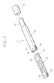
- FIGS. 1 to 3 illustrate a non-heating type flavour inhaler of one embodiment, and this inhaler is provided with a holder 10, a cap 12, and a flavour cartridge 14.
- the holder 10 is integrally molded from a synthetic resin and includes a holder body 16 having a pipe shape and a mouthpiece 18.
- the holder body 16 has an elliptic-shaped outer peripheral surface when seen on a section thereof.
- the mouthpiece 18 extends from one end of the holder body 16 and has an internal passage 20 as illustrated in FIG. 3 . An inner end of this internal passage 20 is connected into the holder body 16.
- the mouthpiece 18 has a connection port 22 providing an inner end thereof, and the connection port 22 protrudes from one end of the holder body 16 into the holder body 16 and opens toward the other end of the holder body 16.
- the connection port 22 has an elliptic inner periphery.
- the cap 12 is also formed of a synthetic resin and can be detachably attached to the mouthpiece 18.
- the flavour cartridge 14 has a thin rectangular stick shape and is detachably accommodated in the holder body 16. That is, the flavour cartridge 14 has a size that can be inserted from the other end of the holder body 16 into the holder body 16. From an inner end of the flavour cartridge 14, a hollow joint 24 is integrally protruded, and the joint 24 provides a connection port at a tip end thereof. When the flavour cartridge 14 is completely inserted into the holder body 16, the joint 24 is inserted into the above described connection port 22, while an outer end of the flavour cartridge 14 is exposed at the other end of the holder body 16.
- the joint 24 has an outer peripheral shape that can conform to an inner peripheral shape of the connection port 22 and thus, only by being inserted into the connection port 22, the joint 24 is connected to the connection port 22 in an airtight manner. That is, the flavour cartridge 14 is held in the holder body 16 by inserting the joint 24 into the connection port 22.
- the holder body 16 has a slot 26 on both side surfaces thereof, respectively. These slots 26 are opened on the other end of the holder body 16 and extend for a predetermined length from the other end toward the one end.
- the flavour cartridge 14 also has a projection 28 on both side surfaces thereof. Each of projections 28 extends from an outer end toward an inner end of the flavour cartridge 14 to the same degree as a length of the slot 26, has a plurality of grooves on an outer surface thereof, and these grooves increase a friction coefficient of the outer surface of the projection 28.
- the above described slot 26 and the projection 28 may be arranged only on one side of the holder body 16 and the flavour cartridge 14.
- the projection 28 is positioned in the slot 26 on the corresponding side and is exposed through the slot 26.
- the user can easily pull out the flavour cartridge 14 from the holder body 16 by pinching the flavour cartridge 14 by fingers at the left and right projections 28.
- the other end of the holder body 16 has a mark 30 drawn on an upper surface thereof, and the mark 30 indicates that the other end of the holder body 16 is a receiving port allowing insertion of the flavour cartridge 14.
- the inner end and the outer end of the flavour cartridge 14 also have marks 32 and 34 drawn on upper surfaces thereof, and the mark 32 indicates an insertion direction of the flavour cartridge 14, while the mark 34 indicates a pulling-out direction of the flavour cartridge 14.
- an outside air inlet chamber 36 is ensured between an inner surface of the holder body 16 and an upper surface of the flavour cartridge 14.
- This outside air inlet chamber 36 extends in a longitudinal direction of the flavour cartridge 14 and is opened as an outside air inlet 38 on the other end of the holder body 16.
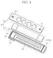
- FIG. 4 illustrates a structure of the above described flavour cartridge 14 in detail.
- the flavour cartridge 14 includes a casing 40 having a longitudinal axis, and the casing 40 accommodates a flavour pouch 42 as a flavour generation source, and the flavour pouch 42 extends along the longitudinal axis.
- the casing 40 has a lower shell 44 and a top plate (first wall) 46, and the lower shell 44 and the top plate 46 are both formed of a synthetic resin.
- the lower shell 44 has an open top, the above described joint 24, and projections 28, and the top plate 46 has the above described marks 32 and 34.
- the lower shell 44 has an upper step 48 on a top thereof, and the upper step 48 extends over the entire periphery of the top.
- the lower shell 44 has a support, that is, a sealing step 50 between its bottom (second wall) and the upper step 48, and the sealing step 50 extends over the entire region of an inner periphery of the lower shell 44.
- the sealing step 50 divides the inside of the lower shell into an upper region and a lower region.
- the above described flavour pouch 42 includes a granular material (not shown) and a permeable sheet 52 wrapping the granular material.
- tobacco granules can be wrapped, for example.
- the tobacco granules are particles obtained by shredding or crushing tobacco leaves and stems or powders obtained by treating the particles and emit a flavour component specific to tobacco.
- the permeable sheet is formed of a nonwoven fabric, for example.
- the granular material can further include particles of flavors such as menthol other than tobacco granules and furthermore can include flavour emitting particles formed from herbs, tea and the like emitting flavour components other than the flavour component specific to tobacco.
- the above described flavour pouch 42 is manufactured by a vertical pillow packaging machine and has traverse seal bands 54 protruded from both ends thereof, respectively, as illustrated in FIG. 5 .
- the traverse seal bands 54 are folded as illustrated in FIG. 6 and overlapped with the flavour pouch 42.
- the flavour pouch 42 is accommodated in the upper region of the lower shell 44, but a substantial height H1 of the upper region, that is, a distance between the sealing step 50 and the upper step 48 is lower than a thickness T (see FIG. 6 ) of the flavour pouch 42 immediately after the flavour pouch 42 is manufactured.
- a communication hole 55 for having the above described joint 24 and the lower region communicate with each other is formed in the lower shell 44.
- the lower region communicates with the mouthpiece 18.
- the lower region provides an internal chamber 56 communicating with the outside air inlet chamber 36 through the upper region.
- a rib 58 as an abutting element is integrally formed at a center thereof.
- This rib 58 extends in the longitudinal direction of the lower shell 44 while leaving both end regions of the internal chamber 56.
- the rib 58 forms the internal chamber 56 annularly.
- a height H2 of the rib 58 from the bottom of the lower shell 44 is equal to a depth of the internal chamber 56 or larger than the depth.
- a top of the rib 58 is positioned on the plane including the sealing step 50 or slightly protrudes from the plane into the upper region.
- the flavour pouch 42 is arranged, and at this time, the two traverse seal bands 54 of the flavour pouch 42 have been already folded, and the outer peripheral portion of the flavour pouch 42 is supported by the sealing step 50 over the whole region, and moreover, the center of the flavour pouch 42 is supported by the rib 58.
- the top plate 46 is fitted with the open top of the lower shell 44 and is supported by the upper step 48 of the lower shell 44.
- a thickness of the top plate 46 is equal to a height from the upper step 48 to the top of the lower shell 44.
- an upper surface and a lower surface of the top plate 46 are positioned flush with the top of the lower shell 44 and the upper step 48, respectively.
- a rectangular inner rim 60 is protruded from the lower surface of the top plate 46, and this inner rim 60 is fitted with an inner peripheral surface of the upper region.
- the outer peripheral surface of the inner rim 60 is in close contact with the inner peripheral surface of the upper region.
- openings 62 are formed on the top plate 46. These openings 62 are juxtaposed at intervals from each other in the longitudinal direction of the flavour cartridge 14 and are positioned above the rib 58.
- top plate 46 An outer peripheral edge of the top plate 46 is firmly bonded to the upper step 48 of the lower shell 44 over the whole region thereof by an ultrasonic deposition or an adhesive. Thus, a space between the outer peripheral edge of the top plate 46 and the upper step 48 is sealed airtightly.
- the height H1 of the upper region is smaller than the thickness T of the flavour pouch 42.
- the top plate 46 presses the flavour pouch 42 on the sealing step 50 and the rib 58 and thus, the flavour pouch 42 is compressed.
- Such compression of the flavour pouch 42 brings the outer peripheral portion of the flavour pouch 42 into close contact with the sealing step 50 and brings the upper surface of the flavour pouch 42 into close contact with the lower surface of the top plate 46.
- a gap between the outer peripheral portion of the flavour pouch 42 and the sealing step 50 is sealed airtightly, and a gap between the lower surface of the top plate 46 and the upper surface of the flavour pouch 42 is also sealed airtightly.
- the air in the outside air inlet chamber 36 of the holder body 16 flows into the flavour pouch 42 through the openings 62 of the top plate 46, passes through the flavour pouch 42 and then, reaches the internal chamber 56. That is, the air in the outside air inlet chamber 36 can reach the internal chamber 56 without bypassing the flavour pouch 42. Therefore, since the air flowing out into the internal chamber 56 passes through the flavour pouch 42 without fail, the flavour component specific to tobacco emitted from the granular material of the flavour pouch 42 is efficiently contained.
- the air containing the flavour component is led into the oral cavity of the user from the internal chamber 56 through the communication hole 55, the joint 24, and the mouthpiece 18 and thus, the user can taste the rich flavour component.
- the lower surface of the flavour pouch 42 is pressed onto the above described rib 58 and thus, such rib 58 prevents movement of the granular material in the flavour pouch 42 and maintains the density of the granular material in the flavour pouch 42 uniform.
- the air passing through the flavour pouch 42 can be effectively brought into contact with the granular material and can contain the flavour component emitted from the granular material more efficiently.
- FIG. 8 illustrates a manufacturing process of the flavour cartridge 14, and this manufacturing process includes, as is obvious from the above described explanation, preparation of the flavour pouch 42, folding of the traverse seal bands 54, preparation of the lower shell 44, accommodation of the flavour pouch 42, and mounting of the top plate 46/compression of the flavour pouch 42.
- the manufacturing process includes a vibration process of vibrating the flavour pouch 42 vertically and/or longitudinally before the flavour pouch 42 is accommodated in the lower shell 44 or before attachment of the top plate 46 after the flavour pouch 42 has been accommodated in the lower shell 44.
- Such vibration process is helpful in making the density of the granular material in the flavour pouch 42 uniform.
- a mechanical vibrator for rotating a cam by a driving source such as an air cylinder or a motor
- an electric vibrator using a piezoelectric element such as an ultrasonic vibrator
- FIG. 2 illustrates a correct insertion attitude of the flavour cartridge 14, but if the flavour cartridge 14 is inserted into the holder body 16 upside down, the flavour cartridge 14 cannot accurately form the outside air inlet 38 or the outside air inlet chamber 36 in cooperation with the holder body 16, and use itself of the flavour inhaler is made impossible.
- FIG. 9 illustrates a state in which the center C is shifted in a width direction of the flavour cartridge 14 from the axis A of the flavour cartridge 14, but the center C may be in a state shifted in a thickness direction of the flavour cartridge 14 from the axis A of the flavour cartridge 14.
- the flavour cartridge 14 is illustrated with a correct insertion attitude, while in a lower side in FIG. 9 , the flavour cartridge 14 is illustrated in a wrong attitude vertically opposite to the correct insertion attitude. If the flavour cartridge 14 is inserted into the holder body 16 in such wrong attitude, the joint 24 is shifted in the width direction of the holder body 16 from a normal position where fitting of the holder body 16 into the connection port 22 is allowed, and fitting of the connection port 22 becomes impossible. Thus, the user notices that the insertion attitude of the flavour cartridge 14 is wrong, and after changing the flavour cartridge 14 into the correct insertion attitude, the user can insert the flavour cartridge 14 into the holder body 16.
- the joint 24 may have a point asymmetric outer peripheral shape.
- the joint 24 illustrated in FIG. 9 has an elliptic outer peripheral surface with different oblatenesses at upper and lower portions thereof. Such joint 24 can also prevent misinsertion of the flavour cartridge 14.
- the present invention is not limited to the above described embodiment but is capable of various variations.
- the lower shell 44 can have a plurality of the ribs 58.
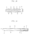
- the lower shell 44 can have a plurality of circular bosses 64. These bosses 64 protrude from the bottom of the lower shell 44 and are juxtaposed in the longitudinal direction of the lower shell 44.
- some of the bosses 64 are preferably positioned at the centers of the openings 62 in the top plate 46, respectively.
- FIGS. 11 and 12 illustrate a flavour inhaler of a variation.
- the flavour inhaler of the variation includes a cover-shaped holder 10a instead of the pipe-shaped holder 10.
- This holder 10a covers an upper half of the flavour cartridge 14 and similarly forms the outside air inlet chamber 36 and the outside air inlet 38 in cooperation with the flavour cartridge 14.
- the above described projection 28 can be arranged on the lower surface of the flavour cartridge 14.
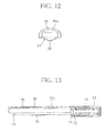
- FIG. 13 illustrates a flavour inhaler of another variation, and this flavour inhaler includes a cover-shaped holder 10b similarly to the holder 10a.
- This holder 10b is different from the holder 10a in a point that the holder 10b forms only the outside air inlet chamber 36 in cooperation with the flavour cartridge 14 and has an opening 66 functioning as the outside air inlet 38 on an upper surface thereof.
- the holder, the cap, the mouthpiece, the casing of the flavour cartridge and the like are not limited to the synthetic resin but it is needless to say that they can be formed of metal, ceramic, lumber and the like.
Landscapes
- Health & Medical Sciences (AREA)
- Engineering & Computer Science (AREA)
- Life Sciences & Earth Sciences (AREA)
- Animal Behavior & Ethology (AREA)
- Anesthesiology (AREA)
- Biomedical Technology (AREA)
- Heart & Thoracic Surgery (AREA)
- Hematology (AREA)
- Bioinformatics & Cheminformatics (AREA)
- Pulmonology (AREA)
- General Health & Medical Sciences (AREA)
- Public Health (AREA)
- Veterinary Medicine (AREA)
- Packages (AREA)
- Containers And Plastic Fillers For Packaging (AREA)
- Packaging Of Annular Or Rod-Shaped Articles, Wearing Apparel, Cassettes, Or The Like (AREA)
Abstract
Description
- The present invention relates to a flavour cartridge and a non-heating type flavour inhaler which provide a flavour component to a user through inhalation without requiring ignition.
- This type of non-heating type flavour inhaler is disclosed in the following Patent Document 1, for example. This flavour inhaler in Patent Document 1 is provided with a holder and a flavour cartridge held in the holder. The holder includes an air inlet, a mouthpiece, and an air communication path connecting the air inlet and the mouthpiece, while the flavour cartridge is arranged so as to divide the air communication path to an upstream side portion and a downstream side portion in the holder.
- In more detail, the flavour cartridge includes a rectangular frame and a flavour pouch held in the frame, and the flavour pouch has a granular material emitting a flavour component and a permeable sheet wrapping the granular material, for example.
- According to the above flavour inhaler, when the user inhales through the mouthpiece, an air flow passing through the flavour pouch and then, going toward the mouthpiece is generated in the air communication path. The flavour component emitted from the granular material in the flavour pouch is carried on the above described air flow into the oral cavity of the user and provides the flavour component to the user.
- Patent Document 1: International Publication No.
2010/095660 (WO 2010/095660 ) - In the case of the flavour inhaler in Patent Document 1, it is not easy to eliminate a gap between an inner surface of the holder and the flavour cartridge or between an inner surface of the frame and the flavour pouch. Thus, such gaps generate a bypass air flow bypassing the flavour pouch as a part of the air flow. Since this bypass flow does not contain the above flavour component, the user cannot effectively taste the flavour component emitted from the granular material.
- In order to solve the above described gaps, high molding accuracy of the holder and the flavour cartridge and moreover, a seal structure for preventing the bypass flow and the like are required, which complicates the structure of the flavour inhaler and incurs an increase in its manufacturing cost.
- An object of the present invention is to provide a flavour cartridge which can efficiently deliver the flavour component emitted from the granular material and a non-heating type flavour inhaler provided with the flavour cartridge with a simple structure.
- The above object is achieved by a flavour cartridge of the present invention, and the flavour cartridge comprises:
- a casing including a longitudinal axis, first and second walls facing each other, and a connection port formed on an outer surface thereof, the first wall having at least one ventilation port;
- a flavour pouch accommodated in a compressed state in the casing and extending along the longitudinal axis, the flavour pouch including a granular material emitting a flavour component and a permeable sheet wrapping the granular material; and
- a support for supporting the flavour pouch in the compressed state in the casing, the support including a sealing step formed over the whole region of an inner periphery of the casing on an inner surface of the casing and sealing the whole periphery of the flavour pouch in close contact with the whole region of an outer periphery of the flavour pouch, and the sealing step ensuring an internal chamber defined between the flavour pouch and the second wall and connected to the connection port.
- According to the above flavour cartridge, an air flowing into the casing from the ventilation port reaches the internal chamber through the flavour pouch and generates an air flow flowing out from the internal chamber through the connection port. Such air flow does not bypass the flavour pouch but reliably passes through the flavour pouch and can efficiently contain the flavour component emitted from the granular material. Therefore, if a user can inhale the air flowing out of the connection port, the user can taste the rich flavour component.
- Specifically, a space between the first wall and the sealing step is smaller than a thickness of the flavour pouch in a non-load state, and the first wall and the sealing step can maintain the flavour pouch in the compressed state in cooperation with each other.
- In this case, the support preferably further includes an abutting element protruding from an inner surface of the second wall and abutting on a surface of the flavour pouch exposed to the internal chamber. More preferably, a top end of the abutting element is substantially positioned in a plane including the sealing step or slightly protrudes from the plane toward the first wall side.
- Specifically, the abutting element is a rib extending along the longitudinal axis of the casing or includes a plurality of bosses arranged at intervals from each other along the longitudinal axis.
- The above abutting element prevents movement of the granular material in the flavour pouch and maintains density of the granular material uniformly over the whole region of the flavour pouch.
- On the other hand, if the flavour pouch is a pillow-packaged product having a traverse seal band at both ends thereof, respectively, the traverse seal bands are preferably folded. Such folding of the traverse seal bands reduces a size of the flavour pouch, and size reduction of the flavour pouch is made possible.
- Moreover, the granular material can contain tobacco granules emitting a flavour component specific to tobacco.
- Moreover, the present invention provides a non-heating type flavour inhaler, and the flavour inhaler comprises:
- the above mentioned flavour cartridge; and
- a holder for detachably holding the flavour cartridge, the holder being provided with a hollow mouthpiece having an inner end allowed to connect to the internal chamber of the flavour cartridge through the connection port, in which
- the first wall of the flavour cartridge held by the holder and the holder ensure an outside air inlet chamber communicating with an outside air in cooperation with each other.
- According to the above described flavour inhaler, when the user inhales through the mouthpiece, an air flow from the outside air inlet chamber to the mouthpiece via the ventilation port, the flavour pouch in the casing, the internal chamber and the connection port is generated.
- Specifically, the casing further has a joint protruding from an outer surface thereof, and the joint has the connection port at a tip end thereof and can be inserted into the inner end of the mouthpiece in an airtight manner. In this case, the flavour cartridge is held by the holder and at the same time, connection between the flavour cartridge and the mouthpiece is established.
- Moreover, the flavour cartridge can further include a prevention mechanism for determining an attitude of the flavour cartridge allowing insertion of the joint into the inner end of the mouthpiece and preventing misattachment of the flavour cartridge to the holder.
- Specifically, if the casing further has an axis extending in the insertion direction of the joint, the prevention mechanism can include the joint having an axis shifted from the axis of the casing or the joint having a point asymmetric outer peripheral shape.
- Moreover, the holder has a pipe shape accommodating the flavour cartridge and further has one end having the mouthpiece, the other end, and a slot which extends from the other end toward the one end and makes partial exposure of the outer surface of the flavour cartridge possible, while the flavour cartridge further includes a protrusion exposed from the slot when accommodated in the holder. Such protrusion facilitates removal of the flavour cartridge from the holder.
- According to the flavour cartridge and the non-heating type flavour inhaler of the present invention, with a simple structure that the flavour pouch in the flavour cartridge is just maintained in a compressed state, when the user inhales through the mouthpiece, the user can inhale only the air having passed through the flavour pouch. Thus, the air inhaled by the user efficiently contains the flavour component emitted from the granular material, and the user can taste the rich flavour component.
-
-
FIG. 1 is a perspective view of a non-heating type flavour inhaler of one embodiment. -
FIG. 2 is an exploded perspective view of the flavour inhaler inFIG. 1 . -
FIG. 3 is a longitudinal sectional view of the flavour inhaler inFIG. 1 . -
FIG. 4 is an exploded perspective view of a flavour cartridge. -
FIG. 5 is a perspective view of a flavour pouch. -
FIG. 6 is a perspective view of the flavour pouch in which traverse seal bands are folded. -
FIG. 7 is a longitudinal sectional view of the flavour cartridge. -
FIG. 8 is a diagram illustrating a manufacturing process of the flavour cartridge. -
FIG. 9 is a view illustrating arrangement of a joint of the flavour cartridge and its shape. -
FIG. 10 is a plan view illustrating a lower shell of a variation of the flavour cartridge. -
FIG. 11 is a longitudinal sectional view illustrating a flavour inhaler of a variation. -
FIG. 12 is an end face view illustrating a distal end of the flavour inhaler inFIG. 11 . -
FIG. 13 is a longitudinal sectional view illustrating a flavour inhaler of another variation. -
FIGS. 1 to 3 illustrate a non-heating type flavour inhaler of one embodiment, and this inhaler is provided with aholder 10, acap 12, and aflavour cartridge 14. Theholder 10 is integrally molded from a synthetic resin and includes aholder body 16 having a pipe shape and amouthpiece 18. Theholder body 16 has an elliptic-shaped outer peripheral surface when seen on a section thereof. Themouthpiece 18 extends from one end of theholder body 16 and has aninternal passage 20 as illustrated inFIG. 3 . An inner end of thisinternal passage 20 is connected into theholder body 16. - In detail, the
mouthpiece 18 has aconnection port 22 providing an inner end thereof, and theconnection port 22 protrudes from one end of theholder body 16 into theholder body 16 and opens toward the other end of theholder body 16. Theconnection port 22 has an elliptic inner periphery. - The
cap 12 is also formed of a synthetic resin and can be detachably attached to themouthpiece 18. - On the other hand, the
flavour cartridge 14 has a thin rectangular stick shape and is detachably accommodated in theholder body 16. That is, theflavour cartridge 14 has a size that can be inserted from the other end of theholder body 16 into theholder body 16. From an inner end of theflavour cartridge 14, a hollow joint 24 is integrally protruded, and the joint 24 provides a connection port at a tip end thereof. When theflavour cartridge 14 is completely inserted into theholder body 16, the joint 24 is inserted into the above describedconnection port 22, while an outer end of theflavour cartridge 14 is exposed at the other end of theholder body 16. - The joint 24 has an outer peripheral shape that can conform to an inner peripheral shape of the
connection port 22 and thus, only by being inserted into theconnection port 22, the joint 24 is connected to theconnection port 22 in an airtight manner. That is, theflavour cartridge 14 is held in theholder body 16 by inserting the joint 24 into theconnection port 22. - Moreover, the
holder body 16 has aslot 26 on both side surfaces thereof, respectively. Theseslots 26 are opened on the other end of theholder body 16 and extend for a predetermined length from the other end toward the one end. On the other hand, theflavour cartridge 14 also has aprojection 28 on both side surfaces thereof. Each ofprojections 28 extends from an outer end toward an inner end of theflavour cartridge 14 to the same degree as a length of theslot 26, has a plurality of grooves on an outer surface thereof, and these grooves increase a friction coefficient of the outer surface of theprojection 28. - The above described
slot 26 and theprojection 28 may be arranged only on one side of theholder body 16 and theflavour cartridge 14. - When the
flavour cartridge 14 is accommodated in theholder body 16, theprojection 28 is positioned in theslot 26 on the corresponding side and is exposed through theslot 26. Thus, when theflavour cartridge 14 is to be removed from theholder body 16, the user can easily pull out theflavour cartridge 14 from theholder body 16 by pinching theflavour cartridge 14 by fingers at the left andright projections 28. - Moreover, the other end of the
holder body 16 has amark 30 drawn on an upper surface thereof, and themark 30 indicates that the other end of theholder body 16 is a receiving port allowing insertion of theflavour cartridge 14. On the other hand, the inner end and the outer end of theflavour cartridge 14 also havemarks mark 32 indicates an insertion direction of theflavour cartridge 14, while themark 34 indicates a pulling-out direction of theflavour cartridge 14. - As is obvious from
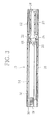
FIG. 3 , when theflavour cartridge 14 is completely accommodated in theholder body 16, an outsideair inlet chamber 36 is ensured between an inner surface of theholder body 16 and an upper surface of theflavour cartridge 14. This outsideair inlet chamber 36 extends in a longitudinal direction of theflavour cartridge 14 and is opened as anoutside air inlet 38 on the other end of theholder body 16. -
FIG. 4 illustrates a structure of the above describedflavour cartridge 14 in detail. - The
flavour cartridge 14 includes acasing 40 having a longitudinal axis, and thecasing 40 accommodates aflavour pouch 42 as a flavour generation source, and theflavour pouch 42 extends along the longitudinal axis. Thecasing 40 has alower shell 44 and a top plate (first wall) 46, and thelower shell 44 and thetop plate 46 are both formed of a synthetic resin. Thelower shell 44 has an open top, the above described joint 24, andprojections 28, and thetop plate 46 has the above describedmarks - In detail, the
lower shell 44 has anupper step 48 on a top thereof, and theupper step 48 extends over the entire periphery of the top. Moreover, thelower shell 44 has a support, that is, a sealingstep 50 between its bottom (second wall) and theupper step 48, and the sealingstep 50 extends over the entire region of an inner periphery of thelower shell 44. The sealingstep 50 divides the inside of the lower shell into an upper region and a lower region. - The above described
flavour pouch 42 includes a granular material (not shown) and apermeable sheet 52 wrapping the granular material. As the granular material, tobacco granules can be wrapped, for example. The tobacco granules are particles obtained by shredding or crushing tobacco leaves and stems or powders obtained by treating the particles and emit a flavour component specific to tobacco. Moreover, the permeable sheet is formed of a nonwoven fabric, for example. - The granular material can further include particles of flavors such as menthol other than tobacco granules and furthermore can include flavour emitting particles formed from herbs, tea and the like emitting flavour components other than the flavour component specific to tobacco.
- The above described
flavour pouch 42 is manufactured by a vertical pillow packaging machine and hastraverse seal bands 54 protruded from both ends thereof, respectively, as illustrated inFIG. 5 . Before theflavour pouch 42 is accommodated in the upper region of thelower shell 44, thetraverse seal bands 54 are folded as illustrated inFIG. 6 and overlapped with theflavour pouch 42. - As illustrated in
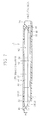
FIG. 7 , theflavour pouch 42 is accommodated in the upper region of thelower shell 44, but a substantial height H1 of the upper region, that is, a distance between the sealingstep 50 and theupper step 48 is lower than a thickness T (seeFIG. 6 ) of theflavour pouch 42 immediately after theflavour pouch 42 is manufactured. - Moreover, as illustrated in
FIG. 7 , acommunication hole 55 for having the above described joint 24 and the lower region communicate with each other is formed in thelower shell 44. Thus, when theflavour cartridge 14 is accommodated in theholder body 16, and the joint 24 of theflavour cartridge 14 is connected to theconnection port 22 of theholder body 16 in an airtight manner, the lower region communicates with themouthpiece 18. Considering a communication path for an air from the above described outsideair inlet chamber 36 through theflavour cartridge 14 to themouthpiece 18, the lower region provides aninternal chamber 56 communicating with the outsideair inlet chamber 36 through the upper region. - Moreover, on the bottom of the
lower shell 44, arib 58 as an abutting element is integrally formed at a center thereof. Thisrib 58 extends in the longitudinal direction of thelower shell 44 while leaving both end regions of theinternal chamber 56. Thus, therib 58 forms theinternal chamber 56 annularly. A height H2 of therib 58 from the bottom of thelower shell 44 is equal to a depth of theinternal chamber 56 or larger than the depth. Thus, a top of therib 58 is positioned on the plane including the sealingstep 50 or slightly protrudes from the plane into the upper region. - In the upper region, the
flavour pouch 42 is arranged, and at this time, the twotraverse seal bands 54 of theflavour pouch 42 have been already folded, and the outer peripheral portion of theflavour pouch 42 is supported by the sealingstep 50 over the whole region, and moreover, the center of theflavour pouch 42 is supported by therib 58. - On the other hand, the
top plate 46 is fitted with the open top of thelower shell 44 and is supported by theupper step 48 of thelower shell 44. A thickness of thetop plate 46 is equal to a height from theupper step 48 to the top of thelower shell 44. Thus, an upper surface and a lower surface of thetop plate 46 are positioned flush with the top of thelower shell 44 and theupper step 48, respectively. - Moreover, a rectangular
inner rim 60 is protruded from the lower surface of thetop plate 46, and thisinner rim 60 is fitted with an inner peripheral surface of the upper region. Thus, the outer peripheral surface of theinner rim 60 is in close contact with the inner peripheral surface of the upper region. - On the
top plate 46, fouropenings 62, for example, are formed. Theseopenings 62 are juxtaposed at intervals from each other in the longitudinal direction of theflavour cartridge 14 and are positioned above therib 58. - An outer peripheral edge of the
top plate 46 is firmly bonded to theupper step 48 of thelower shell 44 over the whole region thereof by an ultrasonic deposition or an adhesive. Thus, a space between the outer peripheral edge of thetop plate 46 and theupper step 48 is sealed airtightly. - As described above, the height H1 of the upper region is smaller than the thickness T of the
flavour pouch 42. Thus, when thetop plate 46 is attached to the open top of thelower shell 44, thetop plate 46 presses theflavour pouch 42 on the sealingstep 50 and therib 58 and thus, theflavour pouch 42 is compressed. Such compression of theflavour pouch 42 brings the outer peripheral portion of theflavour pouch 42 into close contact with the sealingstep 50 and brings the upper surface of theflavour pouch 42 into close contact with the lower surface of thetop plate 46. Thus, a gap between the outer peripheral portion of theflavour pouch 42 and the sealingstep 50 is sealed airtightly, and a gap between the lower surface of thetop plate 46 and the upper surface of theflavour pouch 42 is also sealed airtightly. - When the user inhales through the
mouthpiece 18, as indicated by an arrow inFIG. 7 , the air in the outsideair inlet chamber 36 of theholder body 16 flows into theflavour pouch 42 through theopenings 62 of thetop plate 46, passes through theflavour pouch 42 and then, reaches theinternal chamber 56. That is, the air in the outsideair inlet chamber 36 can reach theinternal chamber 56 without bypassing theflavour pouch 42. Therefore, since the air flowing out into theinternal chamber 56 passes through theflavour pouch 42 without fail, the flavour component specific to tobacco emitted from the granular material of theflavour pouch 42 is efficiently contained. - After that, the air containing the flavour component is led into the oral cavity of the user from the
internal chamber 56 through thecommunication hole 55, the joint 24, and themouthpiece 18 and thus, the user can taste the rich flavour component. - As described above, the lower surface of the
flavour pouch 42 is pressed onto the above describedrib 58 and thus,such rib 58 prevents movement of the granular material in theflavour pouch 42 and maintains the density of the granular material in theflavour pouch 42 uniform. Thus, the air passing through theflavour pouch 42 can be effectively brought into contact with the granular material and can contain the flavour component emitted from the granular material more efficiently. -
FIG. 8 illustrates a manufacturing process of theflavour cartridge 14, and this manufacturing process includes, as is obvious from the above described explanation, preparation of theflavour pouch 42, folding of thetraverse seal bands 54, preparation of thelower shell 44, accommodation of theflavour pouch 42, and mounting of thetop plate 46/compression of theflavour pouch 42. - Preferably, the manufacturing process includes a vibration process of vibrating the
flavour pouch 42 vertically and/or longitudinally before theflavour pouch 42 is accommodated in thelower shell 44 or before attachment of thetop plate 46 after theflavour pouch 42 has been accommodated in thelower shell 44. Such vibration process is helpful in making the density of the granular material in theflavour pouch 42 uniform. - In the vibration process, not only a mechanical vibrator for rotating a cam by a driving source such as an air cylinder or a motor but also an electric vibrator using a piezoelectric element such as an ultrasonic vibrator can be used.
- Moreover, according to the flavour inhaler of this embodiment, when the
flavour cartridge 14 is inserted into theholder body 16, a vertical direction of theflavour cartridge 14 is important. That is,FIG. 2 illustrates a correct insertion attitude of theflavour cartridge 14, but if theflavour cartridge 14 is inserted into theholder body 16 upside down, theflavour cartridge 14 cannot accurately form theoutside air inlet 38 or the outsideair inlet chamber 36 in cooperation with theholder body 16, and use itself of the flavour inhaler is made impossible. - As a mechanism for preventing such misinsertion of the
flavour cartridge 14, as illustrated inFIG. 9 , a center C of the joint 24 of theflavour cartridge 14 is positioned out of an axis A of theflavour cartridge 14.FIG. 9 illustrates a state in which the center C is shifted in a width direction of theflavour cartridge 14 from the axis A of theflavour cartridge 14, but the center C may be in a state shifted in a thickness direction of theflavour cartridge 14 from the axis A of theflavour cartridge 14. - In an upper side in
FIG. 9 , theflavour cartridge 14 is illustrated with a correct insertion attitude, while in a lower side inFIG. 9 , theflavour cartridge 14 is illustrated in a wrong attitude vertically opposite to the correct insertion attitude. If theflavour cartridge 14 is inserted into theholder body 16 in such wrong attitude, the joint 24 is shifted in the width direction of theholder body 16 from a normal position where fitting of theholder body 16 into theconnection port 22 is allowed, and fitting of theconnection port 22 becomes impossible. Thus, the user notices that the insertion attitude of theflavour cartridge 14 is wrong, and after changing theflavour cartridge 14 into the correct insertion attitude, the user can insert theflavour cartridge 14 into theholder body 16. - Instead of shifting the center C of the joint 24 from the axis A of the
flavour cartridge 14, the joint 24 may have a point asymmetric outer peripheral shape. Specifically, the joint 24 illustrated inFIG. 9 has an elliptic outer peripheral surface with different oblatenesses at upper and lower portions thereof. Such joint 24 can also prevent misinsertion of theflavour cartridge 14. - The present invention is not limited to the above described embodiment but is capable of various variations.
- For example, the
lower shell 44 can have a plurality of theribs 58. Moreover, as illustrated inFIG. 10 , instead of therib 58, thelower shell 44 can have a plurality ofcircular bosses 64. Thesebosses 64 protrude from the bottom of thelower shell 44 and are juxtaposed in the longitudinal direction of thelower shell 44. Here, some of thebosses 64 are preferably positioned at the centers of theopenings 62 in thetop plate 46, respectively. -
FIGS. 11 and12 illustrate a flavour inhaler of a variation. - The flavour inhaler of the variation includes a cover-shaped
holder 10a instead of the pipe-shapedholder 10. Thisholder 10a covers an upper half of theflavour cartridge 14 and similarly forms the outsideair inlet chamber 36 and theoutside air inlet 38 in cooperation with theflavour cartridge 14. In the case of the flavour inhaler of the variation, the above describedprojection 28 can be arranged on the lower surface of theflavour cartridge 14. - Moreover,
FIG. 13 illustrates a flavour inhaler of another variation, and this flavour inhaler includes a cover-shapedholder 10b similarly to theholder 10a. Thisholder 10b is different from theholder 10a in a point that theholder 10b forms only the outsideair inlet chamber 36 in cooperation with theflavour cartridge 14 and has anopening 66 functioning as theoutside air inlet 38 on an upper surface thereof. - Moreover, the holder, the cap, the mouthpiece, the casing of the flavour cartridge and the like are not limited to the synthetic resin but it is needless to say that they can be formed of metal, ceramic, lumber and the like.
-
- 10
- holder
- 14
- flavour cartridge
- 16
- holder body
- 18
- mouthpiece
- 22
- connection port
- 24
- joint
- 36
- outside air inlet chamber
- 38
- outside air inlet
- 40
- casing
- 42
- flavour pouch
- 44
- lower shell
- 46
- top plate
- 50
- sealing step
- 55
- communication hole
- 56
- internal chamber
- 58
- rib
- 62
- opening
- 64
- boss
- 66
- opening
Claims (14)
- A flavour cartridge comprising:a casing including a longitudinal axis, first and second walls facing each other, and a connection port formed on outer surfaces thereof, the first wall having at least one ventilation port;a flavour pouch accommodated in a compressed state in said casing and extending along the longitudinal axis, said flavour pouch including a granular material emitting a flavour component and a permeable sheet wrapping the granular material; anda support for supporting said flavour pouch in the compressed state in said casing, said support including a sealing step formed over the whole region of an inner periphery of said casing on an inner surface of said casing and sealing the whole periphery of said flavour pouch in close contact with the whole region of an outer periphery of said flavour pouch, and the sealing step ensuring an internal chamber defined between said flavour pouch and the second wall and connected to the connection port.
- The flavour cartridge according to claim 1,
wherein
a space between the first wall and the sealing step is smaller than a thickness of said flavour pouch in a non-load state, and the first wall and the sealing step maintain said flavour pouch in the compressed state in cooperation with each other. - The flavour cartridge according to claim 2,
wherein
said support further includes an abutting element protruding from an inner surface of the second wall and abutting on a surface of said flavour pouch exposed to the internal chamber. - The flavour cartridge according to claim 3,
wherein
a top end of the abutting element is substantially positioned in a plane including the sealing step or slightly protrudes from the plane toward the first wall side. - The flavour cartridge according to claim 3,
wherein
the abutting element is a rib extending along the longitudinal axis. - The flavour cartridge according to claim 3,
wherein
the abutting element includes a plurality of bosses arranged at intervals from each other along the longitudinal axis. - The flavour cartridge according to claim 2,
wherein
said flavour pouch is a pillow-packaged product having a traverse seal band at both ends thereof, respectively, and the traverse seal bands are folded. - The flavour cartridge according to claim 1,
wherein
the granular material contains tobacco granules emitting a flavour component specific to tobacco. - A non-heating type flavour inhaler comprising:said flavour cartridge according to claim 1; anda holder adapted to detachably hold said flavour cartridge, said holder including a hollow mouthpiece having an inner end allowed to connect to the internal chamber of the flavour cartridge through the connection port, whereinthe first wall of said flavour cartridge held by said holder and said holder ensure an outside air inlet chamber communicating with an outside air in cooperation with each other.
- The non-heating type flavour inhaler according to claim 9, wherein
said casing further has a joint protruding from an outer surface thereof, and the joint has the connection port at a tip end thereof and can be inserted into the inner end of the mouthpiece in an airtight manner. - The non-heating type flavour inhaler according to claim 10, wherein
said flavour cartridge further includes a prevention mechanism adapted to determine an attitude of said flavour cartridge allowing insertion of the joint into the inner end of the mouthpiece and to prevent misattachment of said flavour cartridge to the holder. - The non-heating type flavour inhaler according to claim 11, wherein
said casing further has an axis extending in an insertion direction of the joint; and
said prevention mechanism includes the joint having an axis shifted from the axis of said casing. - The non-heating type flavour inhaler according to claim 11, wherein
the prevention mechanism includes the joint having a point asymmetric outer peripheral shape. - The non-heating type flavour inhaler according to claim 10, wherein
said holder has a pipe shape adapted to accommodate said flavour cartridge, one end having the mouthpiece, the other end, and a slot which extends from the other end toward the one end and makes partial exposure of an outer surface of said flavour cartridge possible; and
said flavour cartridge further includes a protrusion exposed from the slot when accommodated in said holder.
Applications Claiming Priority (1)
| Application Number | Priority Date | Filing Date | Title |
|---|---|---|---|
| PCT/JP2012/051802 WO2013111320A1 (en) | 2012-01-27 | 2012-01-27 | Flavour cartridge and non-heating type flavour inhaler |
Publications (3)
| Publication Number | Publication Date |
|---|---|
| EP2792256A1 true EP2792256A1 (en) | 2014-10-22 |
| EP2792256A4 EP2792256A4 (en) | 2016-03-09 |
| EP2792256B1 EP2792256B1 (en) | 2017-06-14 |
Family
ID=48873086
Family Applications (1)
| Application Number | Title | Priority Date | Filing Date |
|---|---|---|---|
| EP12866687.2A Not-in-force EP2792256B1 (en) | 2012-01-27 | 2012-01-27 | Flavour cartridge and non-heating type flavour inhaler |
Country Status (3)
| Country | Link |
|---|---|
| EP (1) | EP2792256B1 (en) |
| JP (1) | JP5737771B2 (en) |
| WO (1) | WO2013111320A1 (en) |
Cited By (3)
| Publication number | Priority date | Publication date | Assignee | Title |
|---|---|---|---|---|
| US10420372B2 (en) | 2012-10-18 | 2019-09-24 | Japan Tobacco Inc. | Non-burning type flavor inhaler |
| US10653179B2 (en) | 2014-11-10 | 2020-05-19 | Japan Tobacco Inc. | Cartridge and non-burning type flavor inhaler |
| US11504489B2 (en) | 2015-07-17 | 2022-11-22 | Rai Strategic Holdings, Inc. | Contained liquid system for refilling aerosol delivery devices |
Families Citing this family (11)
| Publication number | Priority date | Publication date | Assignee | Title |
|---|---|---|---|---|
| JP5933007B2 (en) * | 2012-08-03 | 2016-06-08 | 日本たばこ産業株式会社 | Non-heated flavor aspirator |
| EP2939553B1 (en) * | 2012-12-28 | 2017-06-28 | Japan Tobacco Inc. | Flavor source for non-combustion inhalation-type tobacco product, and non-combustion inhalation-type tobacco product |
| WO2015049793A1 (en) * | 2013-10-04 | 2015-04-09 | 日本たばこ産業株式会社 | Non-heating type flavor aspirator manufacturing device and manufacturing method |
| PT3166426T (en) * | 2014-07-11 | 2018-12-24 | Philip Morris Products Sa | Aerosol-generating system comprising cartridge detection |
| US10058123B2 (en) | 2014-07-11 | 2018-08-28 | R. J. Reynolds Tobacco Company | Heater for an aerosol delivery device and methods of formation thereof |
| WO2016026756A1 (en) * | 2014-08-21 | 2016-02-25 | Philip Morris Products S.A. | Aerosol-generating device and system |
| WO2016168276A1 (en) | 2015-04-15 | 2016-10-20 | Sansa Corporation (Barbados) Inc. | Flavoring element for an inhalation device |
| US11641874B2 (en) | 2015-09-09 | 2023-05-09 | R.J. Reynolds Tobacco Company | Flavor delivery article |
| MX2019006898A (en) * | 2016-12-19 | 2019-08-22 | Philip Morris Products Sa | Aerosol-generating system having a cartridge with a side aperture. |
| JP6660418B2 (en) * | 2018-04-19 | 2020-03-11 | 日本たばこ産業株式会社 | Cartridge and non-burning type flavor inhaler |
| WO2022024311A1 (en) * | 2020-07-30 | 2022-02-03 | 日本たばこ産業株式会社 | Cartridge for flavor aspirator, and flavor aspirator |
Family Cites Families (5)
| Publication number | Priority date | Publication date | Assignee | Title |
|---|---|---|---|---|
| US3320953A (en) * | 1964-08-06 | 1967-05-23 | Rindner Sheperd | Mouth inhaler simulating smoking device |
| CA1313805C (en) * | 1988-10-19 | 1993-02-23 | Hermann Schwartz | Article for simulation of smoking |
| UA97936C2 (en) * | 2009-02-23 | 2012-03-26 | Джапан Тобакко Инк. | Non-heating type flavor inhaler |
| RU2011138941A (en) * | 2009-02-23 | 2013-11-20 | Джапан Тобакко Инк. | NON-HEATING DEVICE FOR SUCKING TOBACCO FRAGRANCE |
| CA2807635C (en) * | 2010-08-24 | 2015-11-24 | Hirofumi Matsumoto | Non-heating type flavor inhalator and method of manufacturing flavor cartridge |
-
2012
- 2012-01-27 WO PCT/JP2012/051802 patent/WO2013111320A1/en not_active Ceased
- 2012-01-27 EP EP12866687.2A patent/EP2792256B1/en not_active Not-in-force
- 2012-01-27 JP JP2013555078A patent/JP5737771B2/en not_active Expired - Fee Related
Cited By (5)
| Publication number | Priority date | Publication date | Assignee | Title |
|---|---|---|---|---|
| US10420372B2 (en) | 2012-10-18 | 2019-09-24 | Japan Tobacco Inc. | Non-burning type flavor inhaler |
| US10653179B2 (en) | 2014-11-10 | 2020-05-19 | Japan Tobacco Inc. | Cartridge and non-burning type flavor inhaler |
| US11504489B2 (en) | 2015-07-17 | 2022-11-22 | Rai Strategic Holdings, Inc. | Contained liquid system for refilling aerosol delivery devices |
| US11998686B2 (en) | 2015-07-17 | 2024-06-04 | Rai Strategic Holdings, Inc. | Contained liquid system for refilling aerosol delivery devices |
| US12434023B2 (en) | 2015-07-17 | 2025-10-07 | Rai Strategic Holdings, Inc. | Contained liquid system for refilling aerosol delivery devices |
Also Published As
| Publication number | Publication date |
|---|---|
| WO2013111320A1 (en) | 2013-08-01 |
| JPWO2013111320A1 (en) | 2015-05-11 |
| EP2792256A4 (en) | 2016-03-09 |
| EP2792256B1 (en) | 2017-06-14 |
| JP5737771B2 (en) | 2015-06-17 |
Similar Documents
| Publication | Publication Date | Title |
|---|---|---|
| EP2792256B1 (en) | Flavour cartridge and non-heating type flavour inhaler | |
| TWI694780B (en) | Fragrance source unit and fragrance taster | |
| JP5388241B2 (en) | Non-heated flavor aspirator | |
| KR101389143B1 (en) | Non-heating type apparatus for inhaling flavors and method for manufacturing flavor cartridge | |
| AU2020310584B2 (en) | Vapour delivery systems | |
| CN111838772A (en) | Aerosol generating device | |
| EP3995015B1 (en) | Heating assembly and flavor inhaler | |
| JP7742919B2 (en) | Flavor inhaler and insertion guide member | |
| EP3876758B1 (en) | Component for a vapour provision system | |
| JP7256110B2 (en) | Flavor source container and non-combustion type inhaler | |
| TW202241286A (en) | Scent inhaler and manufacturing method thereof | |
| WO2025032304A1 (en) | Aerosolizing system with replaceable capsule | |
| JP7267422B2 (en) | flavor aspirator | |
| JP7267423B2 (en) | flavor aspirator | |
| TW201330787A (en) | Flavor cartridge and non-heated flavor suction apparatus | |
| JP7263518B2 (en) | heating assembly and flavor aspirator | |
| TW202222183A (en) | Flavor inhaler | |
| RU2799807C2 (en) | Component of a vapour providing system | |
| KR20250054063A (en) | Disposable Tank Electronic Cigarette | |
| HK40020717A (en) | Flavor source unit and flavor inhaler | |
| HK1164756B (en) | Non-heating type flavor inhaler |
Legal Events
| Date | Code | Title | Description |
|---|---|---|---|
| PUAI | Public reference made under article 153(3) epc to a published international application that has entered the european phase |
Free format text: ORIGINAL CODE: 0009012 |
|
| 17P | Request for examination filed |
Effective date: 20140711 |
|
| AK | Designated contracting states |
Kind code of ref document: A1 Designated state(s): AL AT BE BG CH CY CZ DE DK EE ES FI FR GB GR HR HU IE IS IT LI LT LU LV MC MK MT NL NO PL PT RO RS SE SI SK SM TR |
|
| DAX | Request for extension of the european patent (deleted) | ||
| RA4 | Supplementary search report drawn up and despatched (corrected) |
Effective date: 20160210 |
|
| RIC1 | Information provided on ipc code assigned before grant |
Ipc: A61M 15/06 20060101ALI20160204BHEP Ipc: A24F 47/00 20060101AFI20160204BHEP |
|
| 17Q | First examination report despatched |
Effective date: 20160913 |
|
| STAA | Information on the status of an ep patent application or granted ep patent |
Free format text: STATUS: EXAMINATION IS IN PROGRESS |
|
| GRAP | Despatch of communication of intention to grant a patent |
Free format text: ORIGINAL CODE: EPIDOSNIGR1 |
|
| STAA | Information on the status of an ep patent application or granted ep patent |
Free format text: STATUS: GRANT OF PATENT IS INTENDED |
|
| INTG | Intention to grant announced |
Effective date: 20170130 |
|
| GRAS | Grant fee paid |
Free format text: ORIGINAL CODE: EPIDOSNIGR3 |
|
| GRAA | (expected) grant |
Free format text: ORIGINAL CODE: 0009210 |
|
| STAA | Information on the status of an ep patent application or granted ep patent |
Free format text: STATUS: THE PATENT HAS BEEN GRANTED |
|
| AK | Designated contracting states |
Kind code of ref document: B1 Designated state(s): AL AT BE BG CH CY CZ DE DK EE ES FI FR GB GR HR HU IE IS IT LI LT LU LV MC MK MT NL NO PL PT RO RS SE SI SK SM TR |
|
| REG | Reference to a national code |
Ref country code: GB Ref legal event code: FG4D |
|
| REG | Reference to a national code |
Ref country code: AT Ref legal event code: REF Ref document number: 900155 Country of ref document: AT Kind code of ref document: T Effective date: 20170615 Ref country code: CH Ref legal event code: EP |
|
| REG | Reference to a national code |
Ref country code: IE Ref legal event code: FG4D |
|
| REG | Reference to a national code |
Ref country code: DE Ref legal event code: R096 Ref document number: 602012033566 Country of ref document: DE |
|
| REG | Reference to a national code |
Ref country code: NL Ref legal event code: MP Effective date: 20170614 |
|
| REG | Reference to a national code |
Ref country code: LT Ref legal event code: MG4D |
|
| PG25 | Lapsed in a contracting state [announced via postgrant information from national office to epo] |
Ref country code: GR Free format text: LAPSE BECAUSE OF FAILURE TO SUBMIT A TRANSLATION OF THE DESCRIPTION OR TO PAY THE FEE WITHIN THE PRESCRIBED TIME-LIMIT Effective date: 20170915 Ref country code: NO Free format text: LAPSE BECAUSE OF FAILURE TO SUBMIT A TRANSLATION OF THE DESCRIPTION OR TO PAY THE FEE WITHIN THE PRESCRIBED TIME-LIMIT Effective date: 20170914 Ref country code: FI Free format text: LAPSE BECAUSE OF FAILURE TO SUBMIT A TRANSLATION OF THE DESCRIPTION OR TO PAY THE FEE WITHIN THE PRESCRIBED TIME-LIMIT Effective date: 20170614 Ref country code: LT Free format text: LAPSE BECAUSE OF FAILURE TO SUBMIT A TRANSLATION OF THE DESCRIPTION OR TO PAY THE FEE WITHIN THE PRESCRIBED TIME-LIMIT Effective date: 20170614 Ref country code: HR Free format text: LAPSE BECAUSE OF FAILURE TO SUBMIT A TRANSLATION OF THE DESCRIPTION OR TO PAY THE FEE WITHIN THE PRESCRIBED TIME-LIMIT Effective date: 20170614 |
|
| REG | Reference to a national code |
Ref country code: AT Ref legal event code: MK05 Ref document number: 900155 Country of ref document: AT Kind code of ref document: T Effective date: 20170614 |
|
| PG25 | Lapsed in a contracting state [announced via postgrant information from national office to epo] |
Ref country code: RS Free format text: LAPSE BECAUSE OF FAILURE TO SUBMIT A TRANSLATION OF THE DESCRIPTION OR TO PAY THE FEE WITHIN THE PRESCRIBED TIME-LIMIT Effective date: 20170614 Ref country code: NL Free format text: LAPSE BECAUSE OF FAILURE TO SUBMIT A TRANSLATION OF THE DESCRIPTION OR TO PAY THE FEE WITHIN THE PRESCRIBED TIME-LIMIT Effective date: 20170614 Ref country code: SE Free format text: LAPSE BECAUSE OF FAILURE TO SUBMIT A TRANSLATION OF THE DESCRIPTION OR TO PAY THE FEE WITHIN THE PRESCRIBED TIME-LIMIT Effective date: 20170614 Ref country code: BG Free format text: LAPSE BECAUSE OF FAILURE TO SUBMIT A TRANSLATION OF THE DESCRIPTION OR TO PAY THE FEE WITHIN THE PRESCRIBED TIME-LIMIT Effective date: 20170914 Ref country code: LV Free format text: LAPSE BECAUSE OF FAILURE TO SUBMIT A TRANSLATION OF THE DESCRIPTION OR TO PAY THE FEE WITHIN THE PRESCRIBED TIME-LIMIT Effective date: 20170614 |
|
| REG | Reference to a national code |
Ref country code: FR Ref legal event code: PLFP Year of fee payment: 7 |
|
| PG25 | Lapsed in a contracting state [announced via postgrant information from national office to epo] |
Ref country code: RO Free format text: LAPSE BECAUSE OF FAILURE TO SUBMIT A TRANSLATION OF THE DESCRIPTION OR TO PAY THE FEE WITHIN THE PRESCRIBED TIME-LIMIT Effective date: 20170614 Ref country code: SK Free format text: LAPSE BECAUSE OF FAILURE TO SUBMIT A TRANSLATION OF THE DESCRIPTION OR TO PAY THE FEE WITHIN THE PRESCRIBED TIME-LIMIT Effective date: 20170614 Ref country code: EE Free format text: LAPSE BECAUSE OF FAILURE TO SUBMIT A TRANSLATION OF THE DESCRIPTION OR TO PAY THE FEE WITHIN THE PRESCRIBED TIME-LIMIT Effective date: 20170614 Ref country code: AT Free format text: LAPSE BECAUSE OF FAILURE TO SUBMIT A TRANSLATION OF THE DESCRIPTION OR TO PAY THE FEE WITHIN THE PRESCRIBED TIME-LIMIT Effective date: 20170614 Ref country code: CZ Free format text: LAPSE BECAUSE OF FAILURE TO SUBMIT A TRANSLATION OF THE DESCRIPTION OR TO PAY THE FEE WITHIN THE PRESCRIBED TIME-LIMIT Effective date: 20170614 |
|
| PG25 | Lapsed in a contracting state [announced via postgrant information from national office to epo] |
Ref country code: ES Free format text: LAPSE BECAUSE OF FAILURE TO SUBMIT A TRANSLATION OF THE DESCRIPTION OR TO PAY THE FEE WITHIN THE PRESCRIBED TIME-LIMIT Effective date: 20170614 Ref country code: SM Free format text: LAPSE BECAUSE OF FAILURE TO SUBMIT A TRANSLATION OF THE DESCRIPTION OR TO PAY THE FEE WITHIN THE PRESCRIBED TIME-LIMIT Effective date: 20170614 Ref country code: PL Free format text: LAPSE BECAUSE OF FAILURE TO SUBMIT A TRANSLATION OF THE DESCRIPTION OR TO PAY THE FEE WITHIN THE PRESCRIBED TIME-LIMIT Effective date: 20170614 Ref country code: IS Free format text: LAPSE BECAUSE OF FAILURE TO SUBMIT A TRANSLATION OF THE DESCRIPTION OR TO PAY THE FEE WITHIN THE PRESCRIBED TIME-LIMIT Effective date: 20171014 |
|
| REG | Reference to a national code |
Ref country code: DE Ref legal event code: R097 Ref document number: 602012033566 Country of ref document: DE |
|
| PLBE | No opposition filed within time limit |
Free format text: ORIGINAL CODE: 0009261 |
|
| STAA | Information on the status of an ep patent application or granted ep patent |
Free format text: STATUS: NO OPPOSITION FILED WITHIN TIME LIMIT |
|
| PG25 | Lapsed in a contracting state [announced via postgrant information from national office to epo] |
Ref country code: DK Free format text: LAPSE BECAUSE OF FAILURE TO SUBMIT A TRANSLATION OF THE DESCRIPTION OR TO PAY THE FEE WITHIN THE PRESCRIBED TIME-LIMIT Effective date: 20170614 |
|
| 26N | No opposition filed |
Effective date: 20180315 |
|
| REG | Reference to a national code |
Ref country code: DE Ref legal event code: R119 Ref document number: 602012033566 Country of ref document: DE |
|
| PG25 | Lapsed in a contracting state [announced via postgrant information from national office to epo] |
Ref country code: SI Free format text: LAPSE BECAUSE OF FAILURE TO SUBMIT A TRANSLATION OF THE DESCRIPTION OR TO PAY THE FEE WITHIN THE PRESCRIBED TIME-LIMIT Effective date: 20170614 |
|
| REG | Reference to a national code |
Ref country code: CH Ref legal event code: PL |
|
| PG25 | Lapsed in a contracting state [announced via postgrant information from national office to epo] |
Ref country code: DE Free format text: LAPSE BECAUSE OF NON-PAYMENT OF DUE FEES Effective date: 20180801 Ref country code: LU Free format text: LAPSE BECAUSE OF NON-PAYMENT OF DUE FEES Effective date: 20180127 |
|
| REG | Reference to a national code |
Ref country code: IE Ref legal event code: MM4A |
|
| REG | Reference to a national code |
Ref country code: BE Ref legal event code: MM Effective date: 20180131 |
|
| PG25 | Lapsed in a contracting state [announced via postgrant information from national office to epo] |
Ref country code: CH Free format text: LAPSE BECAUSE OF NON-PAYMENT OF DUE FEES Effective date: 20180131 Ref country code: BE Free format text: LAPSE BECAUSE OF NON-PAYMENT OF DUE FEES Effective date: 20180131 Ref country code: LI Free format text: LAPSE BECAUSE OF NON-PAYMENT OF DUE FEES Effective date: 20180131 |
|
| PG25 | Lapsed in a contracting state [announced via postgrant information from national office to epo] |
Ref country code: IE Free format text: LAPSE BECAUSE OF NON-PAYMENT OF DUE FEES Effective date: 20180127 |
|
| PG25 | Lapsed in a contracting state [announced via postgrant information from national office to epo] |
Ref country code: MC Free format text: LAPSE BECAUSE OF FAILURE TO SUBMIT A TRANSLATION OF THE DESCRIPTION OR TO PAY THE FEE WITHIN THE PRESCRIBED TIME-LIMIT Effective date: 20170614 |
|
| PG25 | Lapsed in a contracting state [announced via postgrant information from national office to epo] |
Ref country code: MT Free format text: LAPSE BECAUSE OF NON-PAYMENT OF DUE FEES Effective date: 20180127 |
|
| PG25 | Lapsed in a contracting state [announced via postgrant information from national office to epo] |
Ref country code: TR Free format text: LAPSE BECAUSE OF FAILURE TO SUBMIT A TRANSLATION OF THE DESCRIPTION OR TO PAY THE FEE WITHIN THE PRESCRIBED TIME-LIMIT Effective date: 20170614 |
|
| PGFP | Annual fee paid to national office [announced via postgrant information from national office to epo] |
Ref country code: GB Payment date: 20200124 Year of fee payment: 9 Ref country code: IT Payment date: 20200131 Year of fee payment: 9 |
|
| PG25 | Lapsed in a contracting state [announced via postgrant information from national office to epo] |
Ref country code: PT Free format text: LAPSE BECAUSE OF FAILURE TO SUBMIT A TRANSLATION OF THE DESCRIPTION OR TO PAY THE FEE WITHIN THE PRESCRIBED TIME-LIMIT Effective date: 20170614 Ref country code: HU Free format text: LAPSE BECAUSE OF FAILURE TO SUBMIT A TRANSLATION OF THE DESCRIPTION OR TO PAY THE FEE WITHIN THE PRESCRIBED TIME-LIMIT; INVALID AB INITIO Effective date: 20120127 |
|
| PG25 | Lapsed in a contracting state [announced via postgrant information from national office to epo] |
Ref country code: CY Free format text: LAPSE BECAUSE OF FAILURE TO SUBMIT A TRANSLATION OF THE DESCRIPTION OR TO PAY THE FEE WITHIN THE PRESCRIBED TIME-LIMIT Effective date: 20170614 Ref country code: MK Free format text: LAPSE BECAUSE OF NON-PAYMENT OF DUE FEES Effective date: 20170614 |
|
| PGFP | Annual fee paid to national office [announced via postgrant information from national office to epo] |
Ref country code: FR Payment date: 20200121 Year of fee payment: 9 |
|
| PG25 | Lapsed in a contracting state [announced via postgrant information from national office to epo] |
Ref country code: AL Free format text: LAPSE BECAUSE OF FAILURE TO SUBMIT A TRANSLATION OF THE DESCRIPTION OR TO PAY THE FEE WITHIN THE PRESCRIBED TIME-LIMIT Effective date: 20170614 |
|
| GBPC | Gb: european patent ceased through non-payment of renewal fee |
Effective date: 20210127 |
|
| PG25 | Lapsed in a contracting state [announced via postgrant information from national office to epo] |
Ref country code: FR Free format text: LAPSE BECAUSE OF NON-PAYMENT OF DUE FEES Effective date: 20210131 |
|
| PG25 | Lapsed in a contracting state [announced via postgrant information from national office to epo] |
Ref country code: GB Free format text: LAPSE BECAUSE OF NON-PAYMENT OF DUE FEES Effective date: 20210127 |
|
| PG25 | Lapsed in a contracting state [announced via postgrant information from national office to epo] |
Ref country code: IT Free format text: LAPSE BECAUSE OF NON-PAYMENT OF DUE FEES Effective date: 20210127 |