EP2792145B1 - Backwards-compatible delivery of digital cinema content with extended dynamic range - Google Patents
Backwards-compatible delivery of digital cinema content with extended dynamic range Download PDFInfo
- Publication number
- EP2792145B1 EP2792145B1 EP12808596.6A EP12808596A EP2792145B1 EP 2792145 B1 EP2792145 B1 EP 2792145B1 EP 12808596 A EP12808596 A EP 12808596A EP 2792145 B1 EP2792145 B1 EP 2792145B1
- Authority
- EP
- European Patent Office
- Prior art keywords
- video signal
- image
- digital image
- digital cinema
- digital
- Prior art date
- Legal status (The legal status is an assumption and is not a legal conclusion. Google has not performed a legal analysis and makes no representation as to the accuracy of the status listed.)
- Active
Links
- 238000013507 mapping Methods 0.000 claims description 96
- 230000009466 transformation Effects 0.000 claims description 57
- 239000011159 matrix material Substances 0.000 claims description 46
- 238000000034 method Methods 0.000 claims description 44
- 238000007781 pre-processing Methods 0.000 claims description 15
- 230000008569 process Effects 0.000 claims description 4
- 238000012545 processing Methods 0.000 claims description 4
- 239000010410 layer Substances 0.000 description 10
- 230000000007 visual effect Effects 0.000 description 5
- 241000282412 Homo Species 0.000 description 4
- 238000010586 diagram Methods 0.000 description 3
- 238000010606 normalization Methods 0.000 description 3
- 238000012986 modification Methods 0.000 description 2
- 230000004048 modification Effects 0.000 description 2
- 241000887125 Chaptalia nutans Species 0.000 description 1
- 241000023320 Luma <angiosperm> Species 0.000 description 1
- 230000009471 action Effects 0.000 description 1
- 238000013459 approach Methods 0.000 description 1
- 230000008901 benefit Effects 0.000 description 1
- 230000006835 compression Effects 0.000 description 1
- 238000007906 compression Methods 0.000 description 1
- 230000001419 dependent effect Effects 0.000 description 1
- 239000002355 dual-layer Substances 0.000 description 1
- 230000006870 function Effects 0.000 description 1
- 239000004973 liquid crystal related substance Substances 0.000 description 1
- OSWPMRLSEDHDFF-UHFFFAOYSA-N methyl salicylate Chemical compound COC(=O)C1=CC=CC=C1O OSWPMRLSEDHDFF-UHFFFAOYSA-N 0.000 description 1
- 238000009877 rendering Methods 0.000 description 1
- 230000001131 transforming effect Effects 0.000 description 1
Images


Classifications
-
- G—PHYSICS
- G06—COMPUTING; CALCULATING OR COUNTING
- G06T—IMAGE DATA PROCESSING OR GENERATION, IN GENERAL
- G06T5/00—Image enhancement or restoration
- G06T5/90—Dynamic range modification of images or parts thereof
-
- H—ELECTRICITY
- H04—ELECTRIC COMMUNICATION TECHNIQUE
- H04N—PICTORIAL COMMUNICATION, e.g. TELEVISION
- H04N19/00—Methods or arrangements for coding, decoding, compressing or decompressing digital video signals
- H04N19/46—Embedding additional information in the video signal during the compression process
-
- H—ELECTRICITY
- H04—ELECTRIC COMMUNICATION TECHNIQUE
- H04N—PICTORIAL COMMUNICATION, e.g. TELEVISION
- H04N19/00—Methods or arrangements for coding, decoding, compressing or decompressing digital video signals
- H04N19/10—Methods or arrangements for coding, decoding, compressing or decompressing digital video signals using adaptive coding
- H04N19/169—Methods or arrangements for coding, decoding, compressing or decompressing digital video signals using adaptive coding characterised by the coding unit, i.e. the structural portion or semantic portion of the video signal being the object or the subject of the adaptive coding
- H04N19/186—Methods or arrangements for coding, decoding, compressing or decompressing digital video signals using adaptive coding characterised by the coding unit, i.e. the structural portion or semantic portion of the video signal being the object or the subject of the adaptive coding the unit being a colour or a chrominance component
-
- H—ELECTRICITY
- H04—ELECTRIC COMMUNICATION TECHNIQUE
- H04N—PICTORIAL COMMUNICATION, e.g. TELEVISION
- H04N19/00—Methods or arrangements for coding, decoding, compressing or decompressing digital video signals
- H04N19/30—Methods or arrangements for coding, decoding, compressing or decompressing digital video signals using hierarchical techniques, e.g. scalability
-
- H—ELECTRICITY
- H04—ELECTRIC COMMUNICATION TECHNIQUE
- H04N—PICTORIAL COMMUNICATION, e.g. TELEVISION
- H04N19/00—Methods or arrangements for coding, decoding, compressing or decompressing digital video signals
- H04N19/85—Methods or arrangements for coding, decoding, compressing or decompressing digital video signals using pre-processing or post-processing specially adapted for video compression
-
- H—ELECTRICITY
- H04—ELECTRIC COMMUNICATION TECHNIQUE
- H04N—PICTORIAL COMMUNICATION, e.g. TELEVISION
- H04N9/00—Details of colour television systems
- H04N9/64—Circuits for processing colour signals
- H04N9/68—Circuits for processing colour signals for controlling the amplitude of colour signals, e.g. automatic chroma control circuits
-
- H—ELECTRICITY
- H04—ELECTRIC COMMUNICATION TECHNIQUE
- H04N—PICTORIAL COMMUNICATION, e.g. TELEVISION
- H04N9/00—Details of colour television systems
- H04N9/77—Circuits for processing the brightness signal and the chrominance signal relative to each other, e.g. adjusting the phase of the brightness signal relative to the colour signal, correcting differential gain or differential phase
-
- G—PHYSICS
- G06—COMPUTING; CALCULATING OR COUNTING
- G06T—IMAGE DATA PROCESSING OR GENERATION, IN GENERAL
- G06T2200/00—Indexing scheme for image data processing or generation, in general
- G06T2200/16—Indexing scheme for image data processing or generation, in general involving adaptation to the client's capabilities
-
- G—PHYSICS
- G06—COMPUTING; CALCULATING OR COUNTING
- G06T—IMAGE DATA PROCESSING OR GENERATION, IN GENERAL
- G06T2207/00—Indexing scheme for image analysis or image enhancement
- G06T2207/10—Image acquisition modality
- G06T2207/10016—Video; Image sequence
-
- G—PHYSICS
- G06—COMPUTING; CALCULATING OR COUNTING
- G06T—IMAGE DATA PROCESSING OR GENERATION, IN GENERAL
- G06T2207/00—Indexing scheme for image analysis or image enhancement
- G06T2207/10—Image acquisition modality
- G06T2207/10024—Color image
-
- G—PHYSICS
- G06—COMPUTING; CALCULATING OR COUNTING
- G06T—IMAGE DATA PROCESSING OR GENERATION, IN GENERAL
- G06T2207/00—Indexing scheme for image analysis or image enhancement
- G06T2207/20—Special algorithmic details
- G06T2207/20048—Transform domain processing
-
- G—PHYSICS
- G06—COMPUTING; CALCULATING OR COUNTING
- G06T—IMAGE DATA PROCESSING OR GENERATION, IN GENERAL
- G06T2207/00—Indexing scheme for image analysis or image enhancement
- G06T2207/20—Special algorithmic details
- G06T2207/20172—Image enhancement details
- G06T2207/20208—High dynamic range [HDR] image processing
Definitions
- the present disclosure relates to image processing for digital cinema as well as preprocessing and coding of digital image and/or video content. More particularly, an embodiment of the present invention relates to backwards-compatible delivery of digital cinema content with extended range and related preprocessing and coding methods.
- the term 'dynamic range' may relate to a capability of the human visual system (HVS) to perceive a range of intensity (e.g., luminance, luma) in an image, e.g., from darkest darks to brightest brights.
- DR relates to a 'scene-referred' intensity.
- DR may also relate to the ability of a display device to adequately or approximately render an intensity range of a particular breadth. In this sense, DR relates to a 'display-referred' intensity.
- HVS human visual system
- high dynamic range relates to a DR breadth that spans the some 14-15 orders of magnitude of the HVS.
- well adapted humans with essentially normal vision e.g., in one or more of a statistical, biometric or opthamological sense
- an intensity range that spans about 15 orders of magnitude.
- Adapted humans may perceive dim light sources of a few photons.
- these same humans may perceive the near painfully brilliant intensity of the noonday sun in desert, sea or snow (or even glance into the sun, however briefly to prevent damage). This span though is available to 'adapted' humans, e.g., those whose HVS has a time period in which to reset and adjust.
- VDR visual dynamic range'
- HVS HVS
- VDR may relate to a DR that spans 5-6 orders of magnitude.
- future digital cinema systems may be capable of a DR (e.g. VDR) that is higher than the SDR/LDR of conventional digital cinema systems as well as a larger color gamut than the color gamut of conventional digital cinema systems.
- VDR a DR
- the challenge is providing digital cinema content which may be displayed on conventional SDR, small color gamut systems at a standard quality level as well as more advanced VDR, larger color gamut systems at a correspondingly higher quality level.
- US 2011/0194618 A1 discloses a method for compressing visual dynamic range and wide color gamut video.
- a first image stream has a first dynamic range and a first color space.
- the second image stream has a second dynamic range, which is higher than the first dynamic range.
- the first image stream and the second image stream are received in a layered codec.
- the first image stream is in the codec's base layer; the second image stream is in its enhancement layer.
- the first image stream is encoded to obtain an encoded image stream, which is decoded to obtain a decoded image stream.
- the decoded image stream is converted from the first non-linear or linear color space to a second, different color space to obtain a color converted image stream.
- a higher dynamic range image representation of the color converted image stream is generated to obtain a transformed image stream.
- Inverse tone mapping parameters are generated based on the transformed image stream and the second image stream.
- a residual bit stream is generated by subtracting the transformed image stream from the decoded second image stream.
- the second image stream is reconstructed from the inverse tone mapped decoded first image stream by adding the decoded residual data.
- a method of decoding a coded digital cinema bitstream comprising: providing a coded digital cinema bitstream; providing mapping parameters; decoding the coded digital cinema bitstream, the decoding producing a first decoded digital cinema image or video with a first dynamic range and a first color gamut; and expanding the first dynamic range and the first color gamut of the first decoded digital cinema image or video by inverse mapping the first decoded digital cinema image or video with the mapping parameters, thus obtaining a second decoded digital cinema image or video with a second dynamic range higher than the first dynamic range and a second color gamut larger than the first color gamut.
- a method of decoding a coded digital cinema bitstream comprising: providing a coded digital cinema bitstream; providing mapping parameters; decoding the coded digital cinema bitstream, the decoding producing a first decoded digital cinema image or video with a first dynamic range and a first color gamut; and compressing the first dynamic range and the first color gamut of the first decoded digital cinema image or video by forward mapping the first decoded digital cinema image or video with the mapping parameters, thus obtaining a second decoded digital cinema image or video with a second dynamic range lower than the first dynamic range and a second color gamut smaller than the first color gamut.
- a method of pre-processing a digital image or video signal comprising: processing the digital image or video signal by performing color grading to produce a first digital image or video signal having a first dynamic range and a first color gamut, and a second digital image or video signal having a second dynamic range and a second color gamut, the second dynamic range being higher than the first dynamic range and the second color gamut being larger than the first color gamut; producing a first normalized digital image or video signal by pre-processing the first digital image or video signal; producing a second normalized digital image or video signal by pre-processing the second digital image or video signal, wherein the first normalized digital image or video signal is obtainable from the second normalized digital image or video signal through a forward mapping and the second normalized digital image or video signal is obtainable from the first normalized digital image or video signal through an inverse mapping; and producing forward mapping parameters and inverse mapping parameters.
- a method of estimating nonlinear forward mapping parameters for digital image or video signals comprising: providing a first digital image or video signal; providing a second digital image or video signal; providing a matrix; inverting the matrix and applying the inverted matrix to the first digital image or video signal, thus obtaining an intermediate digital image or video signal; and producing nonlinear transformation parameters corresponding to a nonlinear transformation between the second digital image or video signal and the intermediate digital image or video signal.
- a method of estimating matrix forward mapping parameters for digital image or video signals comprising: at the providing a first digital image or video signal; providing a second digital image or video signal; providing a nonlinear transformation; applying the nonlinear transformation to the second digital image or video signal, thus obtaining an intermediate digital image or video signal; and producing matrix transformation parameters corresponding to a matrix transformation between the intermediate digital image or video signal and the first digital image or video signal.
- a method of determining forward mapping parameters for digital image or video signals comprising: (a) setting an input matrix equal to an identity matrix; (b) providing a first digital image or video signal; (c) providing a second digital image or video signal; (d) inverting the input matrix, thus obtaining an inverted matrix and applying the inverted matrix to the first digital image or video signal, thus obtaining an intermediate first digital image or video signal; (e) producing nonlinear transformation parameters corresponding to a nonlinear transformation between the second digital image or video signal and the intermediate first digital image or video signal; (f) applying the nonlinear transformation parameters to the second digital image or video signal, thus obtaining an intermediate second digital image or video signal; (g) producing an estimated matrix corresponding to a matrix transformation between the intermediate second digital image or video signal and the first digital image or video signal; (h) repeating steps (d) through (g), wherein the input matrix of step (d) is set equal to the estimated matrix of step (g); and (i) iterating step (h
- a method of determining forward mapping parameters for digital image or video signals comprising: (a) setting input nonlinear transformation parameters to identity; (b) providing a first digital image or video signal; (c) providing a second digital image or video signal; (d) applying the input nonlinear transformation parameters to the second digital image or video signal, thus obtaining an intermediate second digital image or video signal; (e) producing a matrix corresponding to a matrix transformation between the intermediate second digital image or video signal and the first digital image or video signal; (f) inverting the matrix and applying the inverted matrix to the first digital image or video signal, thus obtaining an intermediate first digital image or video signal; (g) producing estimated nonlinear transformation parameters corresponding to a nonlinear transformation between the second digital image or video signal and the intermediate first digital image or video signal; (h) repeating steps (d) through (g), wherein the input nonlinear transformation parameters of step (d) are set equal to the estimated nonlinear transformation parameters of step (g); and (i) iterating step (
- a system configured to decode a coded digital cinema bitstream, the system comprising: a decoder configured to decode the coded digital cinema bitstream and produce a first decoded digital cinema image or video; and a mapping applicator configured to expand a first dynamic range and a first color gamut of the first decoded digital cinema image or video by inverse mapping the first decoded digital cinema image or video with mapping parameters, thus obtaining a second decoded digital cinema image or video with a second dynamic range higher than the first dynamic range and a second color gamut larger than the first color gamut.
- a system configured to decode a coded digital cinema bitstream, the system comprising: a decoder configured to decode the coded digital cinema bitstream and produce a first decoded digital cinema image or video; and a mapping applicator configured to compress a first dynamic range and a first color gamut of the first decoded digital cinema image or video by forward mapping the first decoded digital cinema image or video with mapping parameters, thus obtaining a second decoded digital cinema image or video with a second dynamic range lower than the first dynamic range and a second color gamut smaller than the first color gamut.
- a system configured to pre-process a digital image or video signal, the system comprising: a color grading module configured to process the digital image or video signal to produce a first digital image or video signal having a first dynamic range and a first color gamut, and a second digital image or video signal having a second dynamic range and a second color gamut, the second dynamic range being higher than the first dynamic range in the second color gamut being larger than the first color gamut; and a preprocessor configured to produce a first normalized digital image or video signal by preprocessing the first digital image or video signal; configured to produce a second normalized digital image or video signal by preprocessing the second digital image or video signal, wherein the first normalized digital image or video signal is obtainable from the second normalized digital image or video signal through a forward mapping and the second normalized digital image or video signal is obtainable from the first normalized digital image or video signal through an inverse mapping; and configured to produce forward mapping parameters and inverse mapping parameters.
- digital cinema refers to the projection of a theatrical motion picture through a digital cinema projection system.
- digital cinema signal refers to a signal representing digital cinema information.
- digital image or video signal refer to digital content which may be, by way of example and not of limitation, live action, rendered CGI (computer-generated imagery), or from any source capable of producing a digital image or video signal.
- FIG. 1A depicts a schematic diagram of a digital cinema decoding architecture in accordance with an embodiment of the present disclosure.
- a coded bitstream (105A) is input to a decoder (110A).
- the bitstream comprises a 12-bit digital cinema signal with a 4:4:4 color representation. Typical input bit rates are in the 125-250 Mbps range.
- the digital cinema signal has a dynamic range, e.g. a 2000:1 dynamic range, and a color gamut, e.g. a P3 color gamut.
- the decoder (110A) can be any decoder able to operate on a digital cinema signal, e.g. a JPEG-2000 decoder.
- the decoder (110A) outputs a first digital cinema image or video (115A) with the same dynamic range and color gamut of the coded input bitstream (105A).
- Inverse mapping is performed on the digital cinema image or video (115A) by a mapping applicator (120A) to expand the dynamic range and color gamut of the image or video.
- a mapping applicator 120A
- the inverse of a nonlinear transformation N followed by a matrix transformation M, i.e. (M ⁇ N) -1 (where the ⁇ indicates the transformation on the right is carried out prior to the transformation on the left) is performed.
- the nonlinear transformation N can be a six segment, cubic spline, while matrix M can be a 3x3 matrix.
- the nonlinear transformation parameters Nj and matrix parameters Mij are sent to the mapping applicator (120A) as mapping metadata (125A).
- the mapping applicator can be implemented as a three-dimensional (3-D) lookup table. While 3-D lookup tables in general are known to those skilled in the art, an embodiment according to the present disclosure may use the 3-D lookup table to produce VDR digital cinema video.
- the mapping applicator (120A) outputs a second 12-bit, 4:4:4 digital cinema image or video (130A) with a higher dynamic range and a larger color gamut than the dynamic range and color gamut of the first digital cinema image or video (115A).
- the second digital cinema image or video (130A) can have a 10000:1 dynamic range, and a color gamut larger than P3.
- the decoding architecture of FIG. 1A provides a dual-layered digital cinema content.
- the output (135A) of the first layer provides a 12-bit, 4:4:4 digital cinema signal (115A) with a first dynamic range and first color gamut
- the output (140A) of the second layer provides a 12-bit, 4:4:4 digital cinema signal (130A) with a second dynamic range higher than the first dynamic range and a second color gamut larger than the first color gamut.
- the architecture of FIG. 1A thus provides a 'single inventory', backwards-compatible, approach for digital cinema content, which can be used both with (a) digital cinema projectors compatible with the first dynamic range and the first color gamut and (b) digital cinema projectors compatible with the second dynamic range and second color gamut.
- Output (135A) will be sent to the first type of projectors, while output (140A) will be sent to the second type of projectors.
- decoder (110A) and mapping applicator (120A) may be located in a projector (150A) and one of the outputs (135A, 140A) can be sent to a screen (160A).
- decoding and mapping architecture of FIG. 1A is a residual-free architecture, where no residual is employed to improve decoding of the digital cinema bitstream (105A).
- the output (135A) represents a conventional/LDR/SDR digital cinema version
- the output (140A) represents a VDR/HDR digital cinema version.
- LDR/SDR or VDR/HDR version will depend on the kind of projector available to theatres.
- FIG. 1B depicts a schematic diagram of a digital cinema decoding architecture in accordance with an alternative embodiment of the present disclosure. Such architecture is similar to the embodiment of FIG. 1A with the following differences.
- Coded bitstream (105B) of FIG. 1B is characterized by a higher dynamic range and a larger color gamut than coded bitstream (105A) of FIG. 1A .
- First digital cinema video (115B) is sent to forward mapping applicator (120B) to produce a second digital cinema video (130B) with a lower dynamic range and a smaller color gamut than the first digital cinema video (115B).
- the output (135B) represents a VDR/HDR digital cinema version
- the output (140B) represents a conventional/LDR/SDR digital cinema version.
- LDR/SDR or VDR/HDR version will depend on the kind of projector available to theatres.
- FIGS. 1A and 1B have been described in terms of conventional/SDR layer vs. VDR/HDR layer, the person skilled in the art will understand that other layered forms and denominations are also possible, such as base layer vs. enhancement layer, first enhancement layer vs. second enhancement layer, and so on.
- FIG. 1A depicts details of a decoding architecture of a digital cinema bitstream.
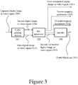
- FIG. 2 depicts instead an example of a pre-processing architecture of a digital cinema image or video prior to coding.
- the pre-processing architecture of FIG. 2 can be used in combination with the decoding architecture of FIG. 1A .
- a captured digital cinema signal (205) is input to a color grading module (210), which outputs a first digital cinema signal (215) with a first dynamic range and color gamut and a second digital cinema signal (220) with a second dynamic range higher than the first dynamic range and a second color gamut larger than the first color gamut.
- signal (215) can be an LDR/SDR signal
- signal (220) can be a VDR/HDR signal.
- the first digital cinema signal (215) and second digital cinema signal (220) are then normalized in a preprocessor (225), thus producing a first normalized digital cinema signal (230) and a second normalized digital cinema signal (235), where the second normalized digital cinema signal (235) is identical to the second digital cinema signal (220).
- the processing through the preprocessor (225) allows the first normalized digital cinema signal (230) and the second normalized digital cinema signal (235) to be related by invertible mapping.
- digital cinema signal (230) can be obtained from digital cinema signal (235) through forward mapping
- digital cinema signal (235) can be obtained from digital cinema signal (230) through inverse mapping.
- the first signal (230) is indicated by SDR* (where * is to indicate a normalized version of input (215)) and the second signal (235) is indicated by VDR* (which is usually equal to the VDR input (220) to numerical precision)
- SDR* (M ⁇ N)VDR*, where M ⁇ N is the forward mapping operator mentioned above.
- the preprocessor (225) also produces inverse and/or forward mapping parameters (240) and/or (245) to be sent, e.g., as metadata.
- Such parameters allow obtaining signal (235) from signal (230) through inverse mapping or signal (230) from signal (235) through forward mapping.
- the mapping parameters obtained and the mapping performed are such that inverse mapping the SDR* signal will exactly reproduce the VDR signal.
- the first normalized digital cinema signal (230) is then encoded in an encoder (250) and sent to a digital cinema system as a coded bitstream (255).
- Encoder (250) can be, for example, an encoder configured to process the first signal (e.g., an SDR* signal (230)) and not the second signal (e.g., a VDR* signal (235)). See, for example, encoder 312 in Fig. 9A of the above mentioned PCT Application PCT/US2011/048861 .
- the second signal e.g., a VDR* signal (335)
- FIG. 3 Such embodiment can be combined with FIG. 1B in a manner similar to the combination of FIGS. 2 and 1A .
- Normalization pre-processing as described in FIGS. 2 and 3 can be used to prepare image or video data for backwards-compatible delivery in distribution systems such as digital cinema systems.
- compatibility between the first and the second digital signals discussed above is obtained at the output of the preprocessor (225/325), where an SDR* signal can be obtained from a VDR* signal and vice versa.
- the embodiments of FIGS. 2-3 allow different realizations (various levels of SDR) of a master image or video (e.g., VDR) to be derived by transforming the master image or video with a transformation that is invertible.
- one such transformation is the M ⁇ N transformation.
- a non-linear transformation N followed by a linear matrix transformation M are performed.
- VDR image or video can be recovered from the SDR image or video:
- SDR and VDR images or videos are often created in separate color grading passes.
- the SDR version typically satisfies Equation (1) approximately, but not necessarily exactly.
- the function of normalization is to determine a modified version of the SDR, i.e. SDR*.
- SDR* and the original VDR satisfy Equation (1) exactly and, furthermore, SDR* and SDR are typically indistinguishable visually.
- SDR and SDR* can be visually indistinguishable approximately 99% of the time, and in cases where there are visible differences, such differences can be visible only when the sequence is halted at a particular frame.
- input bitstream (105A) of FIG. 1A corresponds to the encoded bitstream (255) of FIG. 2
- mapping metadata (125A) of FIG. 1A correspond to inverse mapping parameters (240) of FIG. 2
- the decoding architecture of FIG. 1A can be used in conjunction with the encoding architecture of FIG. 2 .
- the encoding architecture of FIG. 3 can be used with alternative decoding architectures based on that depicted in FIG. 1B .
- Input bitstream (105B) of FIG. 1B corresponds to the encoded bitstream (355) of FIG. 3
- mapping metadata (125B) of FIG. 1B correspond to forward mapping parameters (345) of FIG. 3 .
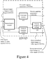
- FIG. 4 depicts a schematic representation of an embodiment of the preprocessor (225/325) of FIGS. 2 and 3 in greater detail.
- First signal (215/315) and second signal (220/320) are sent to a normalization module (410) which determines the forward mapping parameters of nonlinear transformation N j [] and the forward mapping parameters M ij of matrix transformation M. An example of how these parameters are obtained will be later explained in detail.
- Such forward mapping parameters (245/345) are input to a forward mapping module (420) together with the second signal (220/320) in order to obtain the first normalized digital cinema signal (230/330) discussed with reference to FIGS. 2 and 3 , e.g. an SDR* signal.
- Forward mapping parameters (245/345) are also input to an inversion module (430) to obtain inverse mapping parameters (240/340).
- Such inverse mapping parameters (240/340) are input to an inverse mapping module (440) to obtain the second normalized digital cinema signal (235/335) of FIGS. 2 and 3 .
- N and M can be first estimated from the original data.
- N can be modeled as a piecewise polynomial such as a piecewise cubic spline with typically 5-6 segments, while M can be a 3x3 matrix.
- the routine EstimateN[] inverts the matrix M and applies that to the SDR image or video. N is then the transformation between VDR and M -1 •SDR. Similarly, the routine EstimateM[] applies the non-linear transformation to VDR and then M is the transformation between N[VDR] and SDR. Thus, there are two estimation sequences, depending upon whether N or M is first estimated:
- N and M can also be used, such as software optimization packages (e.g. MATLAB).
- software optimization packages e.g. MATLAB
- FIG. 5 depicts a typical non-linearity when clipping occurs at both the low and high limits of intensity.
- the clipping should be softened.
- FIG. 5 depicts varying degrees of softening. The greater the softening the larger the differences between SDR and SDR* for the clipped pixels, so the desire to maintain visual equivalence between SDR and SDR* constrains this softening.
- the methods and systems described in the present disclosure may be implemented in hardware, software, firmware or any combination thereof.
- Features described as blocks, modules or components may be implemented together (e.g., in a logic device such as an integrated logic device) or separately (e.g., as separate connected logic devices).
- the software portion of the methods of the present disclosure may comprise a computer-readable medium which comprises instructions that, when executed, perform, at least in part, the described methods.
- the computer-readable medium may comprise, for example, a random access memory (RAM) and/or a read-only memory (ROM).
- the instructions may be executed by a processor (e.g., a digital signal processor (DSP), an application specific integrated circuit (ASIC), or a field programmable logic array (FPGA)).
- DSP digital signal processor
- ASIC application specific integrated circuit
- FPGA field programmable logic array
Landscapes
- Engineering & Computer Science (AREA)
- Multimedia (AREA)
- Signal Processing (AREA)
- Physics & Mathematics (AREA)
- General Physics & Mathematics (AREA)
- Theoretical Computer Science (AREA)
- Compression Or Coding Systems Of Tv Signals (AREA)
Description
- This application claims the benefit of priority to United States Provisional Patent Application Ser. No.
61/576,141, filed on December 15, 2011 PCT/US2011/048861 , entitled "Extending Image Dynamic Range", filed on August 23, 2011. The present application is also related to PCT ApplicationPCT/US2010/026953 entitled "Layered Compression of High Dynamic Range, Visual Dynamic Range, and Wide Color Gamut Video," filed on March 11, 2010. - The present disclosure relates to image processing for digital cinema as well as preprocessing and coding of digital image and/or video content. More particularly, an embodiment of the present invention relates to backwards-compatible delivery of digital cinema content with extended range and related preprocessing and coding methods.
- As used herein, the term 'dynamic range' (DR) may relate to a capability of the human visual system (HVS) to perceive a range of intensity (e.g., luminance, luma) in an image, e.g., from darkest darks to brightest brights. In this sense, DR relates to a 'scene-referred' intensity. DR may also relate to the ability of a display device to adequately or approximately render an intensity range of a particular breadth. In this sense, DR relates to a 'display-referred' intensity. Unless a particular sense is explicitly specified to have particular significance at any point in the description herein, it should be inferred that the term may be used in either sense, e.g. interchangeably.
- As used herein, the term high dynamic range (HDR) relates to a DR breadth that spans the some 14-15 orders of magnitude of the HVS. For example, well adapted humans with essentially normal vision (e.g., in one or more of a statistical, biometric or opthamological sense) have an intensity range that spans about 15 orders of magnitude. Adapted humans may perceive dim light sources of a few photons. Yet, these same humans may perceive the near painfully brilliant intensity of the noonday sun in desert, sea or snow (or even glance into the sun, however briefly to prevent damage). This span though is available to 'adapted' humans, e.g., those whose HVS has a time period in which to reset and adjust.
- In contrast, the DR over which a human may simultaneously perceive an extensive breadth in intensity range may be somewhat truncated, in relation to HDR. As used herein, the term 'visual dynamic range' (VDR) may relate to the DR that is simultaneously perceivable by a HVS. As used herein, VDR may relate to a DR that spans 5-6 orders of magnitude. Thus while perhaps somewhat narrower in relation to true scene referred HDR, VDR nonetheless represents a wide DR breadth.
- Until fairly recently, displays have had a significantly narrower DR than HDR or VDR. Television (TV) and computer monitor apparatus that use typical cathode ray tube (CRT), liquid crystal display (LCD) with constant fluorescent white back lighting or plasma screen technology may be constrained in their DR rendering capability to approximately three orders of magnitude. Such conventional displays thus typify a low dynamic range (LDR) or standard dynamic range (SDR), in relation to VDR and HDR. Digital cinema systems exhibit some of the same limitations as other display devices.
- Advances in their underlying technology, however, will allow future digital cinema systems to render image and video content with significant improvements in various quality characteristics over the same content, as rendered on today's digital cinema systems. For example, future digital cinema systems may be capable of a DR (e.g. VDR) that is higher than the SDR/LDR of conventional digital cinema systems as well as a larger color gamut than the color gamut of conventional digital cinema systems. The challenge is providing digital cinema content which may be displayed on conventional SDR, small color gamut systems at a standard quality level as well as more advanced VDR, larger color gamut systems at a correspondingly higher quality level.
-
US 2011/0194618 A1 discloses a method for compressing visual dynamic range and wide color gamut video. A first image stream has a first dynamic range and a first color space. The second image stream has a second dynamic range, which is higher than the first dynamic range. The first image stream and the second image stream are received in a layered codec. The first image stream is in the codec's base layer; the second image stream is in its enhancement layer. The first image stream is encoded to obtain an encoded image stream, which is decoded to obtain a decoded image stream. The decoded image stream is converted from the first non-linear or linear color space to a second, different color space to obtain a color converted image stream. A higher dynamic range image representation of the color converted image stream is generated to obtain a transformed image stream. Inverse tone mapping parameters are generated based on the transformed image stream and the second image stream. A residual bit stream is generated by subtracting the transformed image stream from the decoded second image stream. On the decoding end, the second image stream is reconstructed from the inverse tone mapped decoded first image stream by adding the decoded residual data. - The invention is defined by the independent claims. The dependent claims concern optional features of some embodiments of the invention.
-
-
FIGS. 1A and1B depict schematic diagrams of digital cinema decoding architectures in accordance with exemplary embodiments of the present disclosure. -
FIG. 2 is an example of a pre-processing architecture of a digital image or video prior to coding. -
FIG. 3 is an alternative example of a pre-processing architecture of a digital image or video prior to coding. -
FIG. 4 depicts a schematic representation of an embodiment of the preprocessor ofFIGS. 2-3 in greater detail. -
FIG. 5 depicts a typical non-linearity when clipping occurs at both the low and high limits of intensity. - In an example embodiment, a method of decoding a coded digital cinema bitstream is provided, the method comprising: providing a coded digital cinema bitstream; providing mapping parameters; decoding the coded digital cinema bitstream, the decoding producing a first decoded digital cinema image or video with a first dynamic range and a first color gamut; and expanding the first dynamic range and the first color gamut of the first decoded digital cinema image or video by inverse mapping the first decoded digital cinema image or video with the mapping parameters, thus obtaining a second decoded digital cinema image or video with a second dynamic range higher than the first dynamic range and a second color gamut larger than the first color gamut.
- In an example embodiment, a method of decoding a coded digital cinema bitstream is provided, the method comprising: providing a coded digital cinema bitstream; providing mapping parameters; decoding the coded digital cinema bitstream, the decoding producing a first decoded digital cinema image or video with a first dynamic range and a first color gamut; and compressing the first dynamic range and the first color gamut of the first decoded digital cinema image or video by forward mapping the first decoded digital cinema image or video with the mapping parameters, thus obtaining a second decoded digital cinema image or video with a second dynamic range lower than the first dynamic range and a second color gamut smaller than the first color gamut.
- In an example embodiment, a method of pre-processing a digital image or video signal is provided, the method comprising: processing the digital image or video signal by performing color grading to produce a first digital image or video signal having a first dynamic range and a first color gamut, and a second digital image or video signal having a second dynamic range and a second color gamut, the second dynamic range being higher than the first dynamic range and the second color gamut being larger than the first color gamut; producing a first normalized digital image or video signal by pre-processing the first digital image or video signal; producing a second normalized digital image or video signal by pre-processing the second digital image or video signal, wherein the first normalized digital image or video signal is obtainable from the second normalized digital image or video signal through a forward mapping and the second normalized digital image or video signal is obtainable from the first normalized digital image or video signal through an inverse mapping; and producing forward mapping parameters and inverse mapping parameters.
- In an example embodiment, a method of estimating nonlinear forward mapping parameters for digital image or video signals is presented, the method comprising: providing a first digital image or video signal; providing a second digital image or video signal; providing a matrix; inverting the matrix and applying the inverted matrix to the first digital image or video signal, thus obtaining an intermediate digital image or video signal; and producing nonlinear transformation parameters corresponding to a nonlinear transformation between the second digital image or video signal and the intermediate digital image or video signal.
- In an example embodiment, a method of estimating matrix forward mapping parameters for digital image or video signals is presented, the method comprising: at the providing a first digital image or video signal; providing a second digital image or video signal; providing a nonlinear transformation; applying the nonlinear transformation to the second digital image or video signal, thus obtaining an intermediate digital image or video signal; and producing matrix transformation parameters corresponding to a matrix transformation between the intermediate digital image or video signal and the first digital image or video signal.
- In an example embodiment, a method of determining forward mapping parameters for digital image or video signals is presented, the method comprising: (a) setting an input matrix equal to an identity matrix; (b) providing a first digital image or video signal; (c) providing a second digital image or video signal; (d) inverting the input matrix, thus obtaining an inverted matrix and applying the inverted matrix to the first digital image or video signal, thus obtaining an intermediate first digital image or video signal; (e) producing nonlinear transformation parameters corresponding to a nonlinear transformation between the second digital image or video signal and the intermediate first digital image or video signal; (f) applying the nonlinear transformation parameters to the second digital image or video signal, thus obtaining an intermediate second digital image or video signal; (g) producing an estimated matrix corresponding to a matrix transformation between the intermediate second digital image or video signal and the first digital image or video signal; (h) repeating steps (d) through (g), wherein the input matrix of step (d) is set equal to the estimated matrix of step (g); and (i) iterating step (h) until a desired result is obtained.
- In an example embodiment, a method of determining forward mapping parameters for digital image or video signals is presented, the method comprising: (a) setting input nonlinear transformation parameters to identity; (b) providing a first digital image or video signal; (c) providing a second digital image or video signal; (d) applying the input nonlinear transformation parameters to the second digital image or video signal, thus obtaining an intermediate second digital image or video signal; (e) producing a matrix corresponding to a matrix transformation between the intermediate second digital image or video signal and the first digital image or video signal; (f) inverting the matrix and applying the inverted matrix to the first digital image or video signal, thus obtaining an intermediate first digital image or video signal; (g) producing estimated nonlinear transformation parameters corresponding to a nonlinear transformation between the second digital image or video signal and the intermediate first digital image or video signal; (h) repeating steps (d) through (g), wherein the input nonlinear transformation parameters of step (d) are set equal to the estimated nonlinear transformation parameters of step (g); and (i) iterating step (h) until a desired result is obtained.
- In an example embodiment, a system configured to decode a coded digital cinema bitstream is presented, the system comprising: a decoder configured to decode the coded digital cinema bitstream and produce a first decoded digital cinema image or video; and a mapping applicator configured to expand a first dynamic range and a first color gamut of the first decoded digital cinema image or video by inverse mapping the first decoded digital cinema image or video with mapping parameters, thus obtaining a second decoded digital cinema image or video with a second dynamic range higher than the first dynamic range and a second color gamut larger than the first color gamut.
- In an example embodiment, a system configured to decode a coded digital cinema bitstream is provided, the system comprising: a decoder configured to decode the coded digital cinema bitstream and produce a first decoded digital cinema image or video; and a mapping applicator configured to compress a first dynamic range and a first color gamut of the first decoded digital cinema image or video by forward mapping the first decoded digital cinema image or video with mapping parameters, thus obtaining a second decoded digital cinema image or video with a second dynamic range lower than the first dynamic range and a second color gamut smaller than the first color gamut.
- In an example embodiment, a system configured to pre-process a digital image or video signal is provided, the system comprising: a color grading module configured to process the digital image or video signal to produce a first digital image or video signal having a first dynamic range and a first color gamut, and a second digital image or video signal having a second dynamic range and a second color gamut, the second dynamic range being higher than the first dynamic range in the second color gamut being larger than the first color gamut; and a preprocessor configured to produce a first normalized digital image or video signal by preprocessing the first digital image or video signal; configured to produce a second normalized digital image or video signal by preprocessing the second digital image or video signal, wherein the first normalized digital image or video signal is obtainable from the second normalized digital image or video signal through a forward mapping and the second normalized digital image or video signal is obtainable from the first normalized digital image or video signal through an inverse mapping; and configured to produce forward mapping parameters and inverse mapping parameters.
- As used herein, the term digital cinema refers to the projection of a theatrical motion picture through a digital cinema projection system. As used herein, the term digital cinema signal refers to a signal representing digital cinema information.
- As used herein, the terms digital image or video signal refer to digital content which may be, by way of example and not of limitation, live action, rendered CGI (computer-generated imagery), or from any source capable of producing a digital image or video signal.
-
FIG. 1A depicts a schematic diagram of a digital cinema decoding architecture in accordance with an embodiment of the present disclosure. - A coded bitstream (105A) is input to a decoder (110A). In the embodiment of the figure, the bitstream comprises a 12-bit digital cinema signal with a 4:4:4 color representation. Typical input bit rates are in the 125-250 Mbps range. The digital cinema signal has a dynamic range, e.g. a 2000:1 dynamic range, and a color gamut, e.g. a P3 color gamut. The decoder (110A) can be any decoder able to operate on a digital cinema signal, e.g. a JPEG-2000 decoder.
- The decoder (110A) outputs a first digital cinema image or video (115A) with the same dynamic range and color gamut of the coded input bitstream (105A).
- Inverse mapping is performed on the digital cinema image or video (115A) by a mapping applicator (120A) to expand the dynamic range and color gamut of the image or video. In accordance with an embodiment of the disclosure, the inverse of a nonlinear transformation N followed by a matrix transformation M, i.e. (M∘N)-1 (where the ∘ indicates the transformation on the right is carried out prior to the transformation on the left), is performed. By way of example, the nonlinear transformation N can be a six segment, cubic spline, while matrix M can be a 3x3 matrix. The nonlinear transformation parameters Nj and matrix parameters Mij are sent to the mapping applicator (120A) as mapping metadata (125A). In one embodiment, the mapping applicator can be implemented as a three-dimensional (3-D) lookup table. While 3-D lookup tables in general are known to those skilled in the art, an embodiment according to the present disclosure may use the 3-D lookup table to produce VDR digital cinema video.
- The mapping applicator (120A) outputs a second 12-bit, 4:4:4 digital cinema image or video (130A) with a higher dynamic range and a larger color gamut than the dynamic range and color gamut of the first digital cinema image or video (115A). For example, the second digital cinema image or video (130A) can have a 10000:1 dynamic range, and a color gamut larger than P3.
- Therefore, the decoding architecture of
FIG. 1A provides a dual-layered digital cinema content. In particular, the output (135A) of the first layer provides a 12-bit, 4:4:4 digital cinema signal (115A) with a first dynamic range and first color gamut, while the output (140A) of the second layer provides a 12-bit, 4:4:4 digital cinema signal (130A) with a second dynamic range higher than the first dynamic range and a second color gamut larger than the first color gamut. - The architecture of
FIG. 1A thus provides a 'single inventory', backwards-compatible, approach for digital cinema content, which can be used both with (a) digital cinema projectors compatible with the first dynamic range and the first color gamut and (b) digital cinema projectors compatible with the second dynamic range and second color gamut. Output (135A) will be sent to the first type of projectors, while output (140A) will be sent to the second type of projectors. Alternatively, decoder (110A) and mapping applicator (120A) may be located in a projector (150A) and one of the outputs (135A, 140A) can be sent to a screen (160A). - The person skilled in the art will appreciate that the decoding and mapping architecture of
FIG. 1A is a residual-free architecture, where no residual is employed to improve decoding of the digital cinema bitstream (105A). - In one embodiment, the output (135A) represents a conventional/LDR/SDR digital cinema version, while the output (140A) represents a VDR/HDR digital cinema version. As mentioned above, use of the LDR/SDR or VDR/HDR version will depend on the kind of projector available to theatres.
-
FIG. 1B depicts a schematic diagram of a digital cinema decoding architecture in accordance with an alternative embodiment of the present disclosure. Such architecture is similar to the embodiment ofFIG. 1A with the following differences. Coded bitstream (105B) ofFIG. 1B is characterized by a higher dynamic range and a larger color gamut than coded bitstream (105A) ofFIG. 1A . First digital cinema video (115B) is sent to forward mapping applicator (120B) to produce a second digital cinema video (130B) with a lower dynamic range and a smaller color gamut than the first digital cinema video (115B). - In one embodiment, the output (135B) represents a VDR/HDR digital cinema version, while the output (140B) represents a conventional/LDR/SDR digital cinema version. As mentioned above, use of the LDR/SDR or VDR/HDR version will depend on the kind of projector available to theatres.
- While the dual-layer architectures of
FIGS. 1A and1B have been described in terms of conventional/SDR layer vs. VDR/HDR layer, the person skilled in the art will understand that other layered forms and denominations are also possible, such as base layer vs. enhancement layer, first enhancement layer vs. second enhancement layer, and so on. - As noted above,
FIG. 1A depicts details of a decoding architecture of a digital cinema bitstream.FIG. 2 depicts instead an example of a pre-processing architecture of a digital cinema image or video prior to coding. In a particular embodiment of the present disclosure, the pre-processing architecture ofFIG. 2 can be used in combination with the decoding architecture ofFIG. 1A . - As depicted in
FIG. 2 , a captured digital cinema signal (205) is input to a color grading module (210), which outputs a first digital cinema signal (215) with a first dynamic range and color gamut and a second digital cinema signal (220) with a second dynamic range higher than the first dynamic range and a second color gamut larger than the first color gamut. By way of example, signal (215) can be an LDR/SDR signal, while signal (220) can be a VDR/HDR signal. - The first digital cinema signal (215) and second digital cinema signal (220) are then normalized in a preprocessor (225), thus producing a first normalized digital cinema signal (230) and a second normalized digital cinema signal (235), where the second normalized digital cinema signal (235) is identical to the second digital cinema signal (220). The processing through the preprocessor (225) allows the first normalized digital cinema signal (230) and the second normalized digital cinema signal (235) to be related by invertible mapping. In other words, once normalized, digital cinema signal (230) can be obtained from digital cinema signal (235) through forward mapping, while digital cinema signal (235) can be obtained from digital cinema signal (230) through inverse mapping. Assuming, for example, that the first signal (230) is indicated by SDR* (where * is to indicate a normalized version of input (215)) and the second signal (235) is indicated by VDR* (which is usually equal to the VDR input (220) to numerical precision), the following relationship holds true: SDR* = (M∘N)VDR*, where M∘N is the forward mapping operator mentioned above. The preprocessor (225) also produces inverse and/or forward mapping parameters (240) and/or (245) to be sent, e.g., as metadata. Such parameters allow obtaining signal (235) from signal (230) through inverse mapping or signal (230) from signal (235) through forward mapping. The mapping parameters obtained and the mapping performed are such that inverse mapping the SDR* signal will exactly reproduce the VDR signal.
- The first normalized digital cinema signal (230) is then encoded in an encoder (250) and sent to a digital cinema system as a coded bitstream (255). Encoder (250) can be, for example, an encoder configured to process the first signal (e.g., an SDR* signal (230)) and not the second signal (e.g., a VDR* signal (235)). See, for example, encoder 312 in Fig. 9A of the above mentioned PCT Application
PCT/US2011/048861 . In an alternative embodiment, the second signal (e.g., a VDR* signal (335)) may be encoded to allow obtaining an SDR* signal from a VDR* signal. This alternative embodiment is depicted inFIG. 3 . Such embodiment can be combined withFIG. 1B in a manner similar to the combination ofFIGS. 2 and1A . - Normalization pre-processing as described in
FIGS. 2 and3 can be used to prepare image or video data for backwards-compatible delivery in distribution systems such as digital cinema systems. As noted above, compatibility between the first and the second digital signals discussed above is obtained at the output of the preprocessor (225/325), where an SDR* signal can be obtained from a VDR* signal and vice versa. In other words, the embodiments ofFIGS. 2-3 allow different realizations (various levels of SDR) of a master image or video (e.g., VDR) to be derived by transforming the master image or video with a transformation that is invertible. - According to the embodiment described above, one such transformation is the M∘N transformation. In other words, a non-linear transformation N followed by a linear matrix transformation M are performed. Such transformation (where repeated indices imply summation and where the higher and lower dynamic range indicators are depicted as VDR and SDR by way of example) can be seen as follows:

- When the N and M transformation are invertible, the VDR image or video can be recovered from the SDR image or video:

- In practice, SDR and VDR images or videos are often created in separate color grading passes. The SDR version typically satisfies Equation (1) approximately, but not necessarily exactly. The function of normalization is to determine a modified version of the SDR, i.e. SDR*. SDR* and the original VDR satisfy Equation (1) exactly and, furthermore, SDR* and SDR are typically indistinguishable visually. SDR and SDR* can be visually indistinguishable approximately 99% of the time, and in cases where there are visible differences, such differences can be visible only when the sequence is halted at a particular frame.
- In an embodiment of the present disclosure, input bitstream (105A) of
FIG. 1A corresponds to the encoded bitstream (255) ofFIG. 2 , while mapping metadata (125A) ofFIG. 1A correspond to inverse mapping parameters (240) ofFIG. 2 . Therefore, according to such embodiment, the decoding architecture ofFIG. 1A can be used in conjunction with the encoding architecture ofFIG. 2 . In particular, assuming that the inverse mapping ofFIG. 1A is performed by inverse transformation (M∘N)-1, the mapping ofFIG. 2 is performed by transformation M∘N as later explained in greater detail. Similarly, the encoding architecture ofFIG. 3 can be used with alternative decoding architectures based on that depicted inFIG. 1B . Input bitstream (105B) ofFIG. 1B corresponds to the encoded bitstream (355) ofFIG. 3 , while mapping metadata (125B) ofFIG. 1B correspond to forward mapping parameters (345) ofFIG. 3 . - Reference will now be made to
FIG. 4 , which depicts a schematic representation of an embodiment of the preprocessor (225/325) ofFIGS. 2 and3 in greater detail. First signal (215/315) and second signal (220/320) are sent to a normalization module (410) which determines the forward mapping parameters of nonlinear transformation Nj[] and the forward mapping parameters Mij of matrix transformation M. An example of how these parameters are obtained will be later explained in detail. - Such forward mapping parameters (245/345) are input to a forward mapping module (420) together with the second signal (220/320) in order to obtain the first normalized digital cinema signal (230/330) discussed with reference to
FIGS. 2 and3 , e.g. an SDR* signal. Forward mapping parameters (245/345) are also input to an inversion module (430) to obtain inverse mapping parameters (240/340). Such inverse mapping parameters (240/340) are input to an inverse mapping module (440) to obtain the second normalized digital cinema signal (235/335) ofFIGS. 2 and3 . - The parameters for N and M can be first estimated from the original data. By way of example, such parameters can be determined iteratively using two routines "EstimateN" and "EstimateM" that estimate N or M while the other is fixed:


- As mentioned above, N can be modeled as a piecewise polynomial such as a piecewise cubic spline with typically 5-6 segments, while M can be a 3x3 matrix.
- The routine EstimateN[] inverts the matrix M and applies that to the SDR image or video. N is then the transformation between VDR and M-1•SDR. Similarly, the routine EstimateM[] applies the non-linear transformation to VDR and then M is the transformation between N[VDR] and SDR. Thus, there are two estimation sequences, depending upon whether N or M is first estimated:
- Sequence A:


- Sequence B:


- Other methods for determining N and M can also be used, such as software optimization packages (e.g. MATLAB).
- In most cases the parameters for N[] and M determined as described above are sufficient. In some cases, the non-linearity must be slightly modified due to the so-called "clipping" in the SDR signal.
FIG. 5 depicts a typical non-linearity when clipping occurs at both the low and high limits of intensity. In order to make N[] invertible, the clipping should be softened.FIG. 5 depicts varying degrees of softening. The greater the softening the larger the differences between SDR and SDR* for the clipped pixels, so the desire to maintain visual equivalence between SDR and SDR* constrains this softening. - The methods and systems described in the present disclosure may be implemented in hardware, software, firmware or any combination thereof. Features described as blocks, modules or components may be implemented together (e.g., in a logic device such as an integrated logic device) or separately (e.g., as separate connected logic devices). The software portion of the methods of the present disclosure may comprise a computer-readable medium which comprises instructions that, when executed, perform, at least in part, the described methods. The computer-readable medium may comprise, for example, a random access memory (RAM) and/or a read-only memory (ROM). The instructions may be executed by a processor (e.g., a digital signal processor (DSP), an application specific integrated circuit (ASIC), or a field programmable logic array (FPGA)).
- All patents and publications mentioned in the specification may be indicative of the levels of skill of those skilled in the art to which the disclosure pertains.
- It is to be understood that the disclosure is not limited to particular methods or systems, which can, of course, vary. It is also to be understood that the terminology used herein is for the purpose of describing particular embodiments only, and is not intended to be limiting. As used in this specification and the appended claims, the singular forms "a," "an," and "the" include plural referents unless the content clearly dictates otherwise. The term "plurality" includes two or more referents unless the content clearly dictates otherwise. Unless defined otherwise, all technical and scientific terms used herein have the same meaning as commonly understood by one of ordinary skill in the art to which the disclosure pertains.
- The examples set forth above are provided to give those of ordinary skill in the art a complete disclosure and description of how to make and use the embodiments of the backwards-compatible delivery of digital cinema content with extended range and related preprocessing and coding methods of the disclosure, and are not intended to limit the scope of what the inventors regard as their disclosure. Modifications of the above-described modes for carrying out the disclosure may be used by persons of skill in the video art, and are intended to be within the scope of the following claims.
- A number of embodiments of the disclosure have been described. Nevertheless, it will be understood that various modifications may be made without departing from the scope of the present disclosure. Accordingly, other embodiments are within the scope of the following claims.
Claims (13)
- A method of producing normalized digital image or video signals (230, 235, 330, 335) and mapping parameters (240, 245, 340, 345) from a captured digital image or video signal (205, 305), the method comprising:processing the digital image or video signal (205, 305) by performing color grading to produce a first digital image or video signal (215, 315) having a first dynamic range and a first color gamut, and a second digital image or video signal (220, 320) having a second dynamic range and a second color gamut, the second dynamic range being higher than the first dynamic range and the second color gamut being larger than the first color gamut;producing forward mapping parameters (245, 345) for a forward mapping, which is an invertible mapping, and producing inverse mapping parameters (240, 340) for an inverse mapping which is the inverse of the forward mapping;producing a first normalized digital image or video signal (230, 330) by performing the forward mapping on the second digital image or video signal (220, 320);producing a second normalized digital image or video signal (235, 335) by performing the inverse mapping on the first normalized digital image or video signal (230, 330) such that the second normalized digital image or video signal (235, 335) is equal to the second digital image or video signal (220, 320) within numerical precision, and wherein the first normalized digital image or video signal (230, 330) is obtainable from the second normalized digital image or video signal (235, 335) through the forward mapping;wherein the producing of the first normalized digital image or video signal (230, 330) through the forward mapping comprises:performing an invertible non-linear transformation N on the second digital image or video signal (220, 320), andupon the performance of the non-linear transformation, performing an invertible matrix transformation M to obtain the first normalized digital image or video signal (230, 330);wherein the producing of the forward mapping parameters (245, 345) comprises:(a1) setting an input matrix (M0) equal to an identity matrix;(b1) inverting the input matrix (M0) to obtain an inverted matrix and applying the inverted matrix to the first digital image or video signal (215, 315), thus obtaining an intermediate first digital image or video signal;(c1) producing forward mapping parameters by determining estimated nonlinear transformation parameters (N0) corresponding to a nonlinear transformation N between the second digital image or video signal (220, 320) and the intermediate first digital image or video signal;(d1) applying the estimated nonlinear transformation parameters (N1) to the second digital image or video signal (220, 320), thus obtaining an intermediate second digital image or video signal;(e1) producing forward mapping parameters by determining an estimated matrix (M1) corresponding to the matrix transformation M between the intermediate second digital image or video signal and the first digital image or video signal (215, 315);(f1) repeating steps (b1) through (e1), wherein the input matrix of step (b1) is set equal to the estimated matrix of step (el); and(g1) iterating step (f1) until a desired result is obtained;or the producing of the forward mapping parameters (245, 345) comprises:(a2) setting input nonlinear transformation parameters (N0) to identity;(b2) applying the input nonlinear transformation parameters to the second digital image or video signal (220, 320) to obtain an intermediate second digital image or video signal;(c2) producing forward mapping parameters by determining an estimated matrix (M0) corresponding to a matrix transformation M between the intermediate second digital image or video signal and the first digital image or video signal (215, 315);(d2) inverting the matrix M and applying the inverted matrix M -1 to the first digital image or video signal (215, 315), thus obtaining an intermediate first digital image or video signal;(e2) producing forward mapping parameters (245, 345) by determining estimated nonlinear transformation parameters (N1) corresponding to the nonlinear transformation N between the second digital image or video signal (220, 320) and the intermediate first digital image or video signal;(f2) repeating steps (b2) through (e2), wherein the input nonlinear transformation parameters of step (b2) are set equal to the estimated nonlinear transformation parameters of step (e2); and(g2) iterating step (f2) until a desired result is obtained.
- The method of claim 1, wherein performing the forward mapping comprises calculating:
 wherein
 wherein Ni is the i-th component of the non-linear transformation N,wherein Mi,j is the i,j-th element of the linear matrix transformation M, andwherein
- The method of claim 1 or claim 2, wherein performing the inverse mapping comprises calculating:
 wherein
 wherein
 wherein
 wherein
- The method of any of claims 1-3, further comprising:producing a coded digital cinema bitstream (105A, 255), wherein the coded digital cinema bitstream (105A, 255) comprises the first normalized digital cinema image or video signal (115A, 230).
- The method of any of claims 1-3, further comprising:producing a coded digital cinema bitstream (105A, 255), wherein the coded digital cinema bitstream (105A, 255) comprises the second normalized digital cinema image or video signal (115B, 335).
- A method of decoding a coded digital cinema bitstream (105A, 255) with inverse mapping parameters (125A, 240), wherein the coded digital cinema bitstream (105A, 255) comprises the first normalized digital cinema image or video signal (115A, 230), and wherein the first normalized digital cinema image or video signal (115A, 230) and the inverse mapping parameters (125A, 240) are produced according to the method of any of claims 1 to 5, the method comprising:decoding the coded digital cinema bitstream (105A, 255), the decoding producing the first normalized digital cinema image or video signal (115A, 230);expanding the first dynamic range and the first color gamut of the first normalized digital cinema image or video signal (115A, 230) by performing the inverse mapping on the first normalized digital cinema image or video signal (115A, 230) with the inverse mapping parameters (125A, 240) to obtain the second normalized digital cinema image or video signal (130A, 235).
- A method of decoding a coded digital cinema bitstream (105B, 355) with forward mapping parameters (125B, 345), wherein the coded digital cinema bitstream (105B, 355) comprises the second normalized digital cinema image or video signal (115B, 335), and wherein the second normalized digital cinema image or video signal (115B, 335) and the forward mapping parameters (125B, 345) are produced according to the method of any of claims 1 to 5, the method comprising:decoding the coded digital cinema bitstream (105B, 355), the decoding producing the second normalized digital cinema image or video signal (115B, 335);compressing the second dynamic range and the second color gamut of the second normalized digital cinema image or video signal (115B, 335) by performing the forward mapping on the second normalized digital cinema image or video signal (115B, 335) with the forward mapping parameters (125B, 345) to obtain the first normalized digital cinema image or video signal (130B, 330).
- The method of any of claims 1 to 7, wherein the nonlinear transformation N comprises a six segment, cubic spline.
- The method of any one of claims 1 to 8, wherein the matrix transformation uses a 3x3 matrix.
- A system configured to decode a coded digital cinema bitstream (105A, 255) with inverse mapping parameters (125A, 240) by performing the method of claim 6, the system comprising:a decoder (110A) that is configured to decode the coded digital cinema bitstream (105A, 255) and produce the first normalized digital cinema image or video signal (115A, 230); anda mapping applicator (120A) that is configured to expand the first dynamic range and the first color gamut of the first normalized digital cinema image or video signal (115A, 230) by performing the inverse mapping on the first normalized digital cinema image or video signal (115A, 230) with the inverse mapping parameters (125A, 240) to obtain the second normalized digital cinema image or video signal (130A, 235) with the second dynamic range that is higher than the first dynamic range and the second color gamut that is larger than the first color gamut.
- A system configured to decode a coded digital cinema bitstream (105B, 355) with forward mapping parameters by performing the method of claim 7, the system comprising:a decoder (110B) that is configured to decode the coded digital cinema bitstream (105B, 355) and produce the second normalized digital cinema image or video signal (115B, 335); anda mapping applicator (120B) that is configured to compress the second dynamic range and the second color gamut of the second normalized digital cinema image or video signal (115B, 335) by performing the forward mapping on the second normalized digital cinema image or video signal (115B, 335) with the forward mapping parameters (125B, 345) to obtain the first normalized digital cinema image or video signal (130B, 330) with the first dynamic range that is lower than the second dynamic range and the first color gamut that is smaller than the second color gamut.
- A system configured to produce normalized digital image or video signals (230, 235, 330, 335) and mapping parameters (240, 245, 340, 345) from a digital image or video signal (205, 305) by performing the method of any one of claims 1 to 5, the system comprising:a color grading module (210, 310) that is configured to process the digital image or video signal (205, 305) to produce the first digital image or video signal (215, 315) and the second digital image or video signal (220, 320); anda preprocessor (225, 325) that is configured to produce the first normalized digital image or video signal (230, 330) by preprocessing the first digital image or video signal (215, 315); configured to produce the second normalized digital image or video signal (235, 335) by preprocessing the second digital image or video signal (220, 320); and configured to produce the forward mapping parameters (245, 345) and the inverse mapping parameters (240, 340).
- A computer-readable medium containing a set of instructions that causes a computer to perform the method recited in one or more of claims 1 to 9.
Applications Claiming Priority (2)
| Application Number | Priority Date | Filing Date | Title |
|---|---|---|---|
| US201161576141P | 2011-12-15 | 2011-12-15 | |
| PCT/US2012/068275 WO2013090120A1 (en) | 2011-12-15 | 2012-12-06 | Backwards-compatible delivery of digital cinema content with extended dynamic range |
Publications (2)
| Publication Number | Publication Date |
|---|---|
| EP2792145A1 EP2792145A1 (en) | 2014-10-22 |
| EP2792145B1 true EP2792145B1 (en) | 2018-03-21 |
Family
ID=47459142
Family Applications (1)
| Application Number | Title | Priority Date | Filing Date |
|---|---|---|---|
| EP12808596.6A Active EP2792145B1 (en) | 2011-12-15 | 2012-12-06 | Backwards-compatible delivery of digital cinema content with extended dynamic range |
Country Status (3)
| Country | Link |
|---|---|
| US (2) | US8872981B1 (en) |
| EP (1) | EP2792145B1 (en) |
| WO (1) | WO2013090120A1 (en) |
Families Citing this family (18)
| Publication number | Priority date | Publication date | Assignee | Title |
|---|---|---|---|---|
| US8866975B1 (en) | 2013-05-02 | 2014-10-21 | Dolby Laboratories Licensing Corporation | Backwards-compatible delivery of digital cinema content with higher dynamic range and related preprocessing and coding methods |
| TWI630820B (en) | 2013-07-19 | 2018-07-21 | 新力股份有限公司 | File generation device, file generation method, file reproduction device, and file reproduction method |
| TWI630821B (en) | 2013-07-19 | 2018-07-21 | 新力股份有限公司 | File generation device, file generation method, file reproduction device, and file reproduction method |
| TWI632810B (en) * | 2013-07-19 | 2018-08-11 | 新力股份有限公司 | Data generating device, data generating method, data reproducing device, and data reproducing method |
| CN105745914B (en) | 2013-11-22 | 2018-09-07 | 杜比实验室特许公司 | Method and system for inverse tone mapping (ITM) |
| US10542265B2 (en) * | 2014-09-09 | 2020-01-21 | Dolby Laboratories Licensing Corporation | Self-adaptive prediction method for multi-layer codec |
| US9560330B2 (en) * | 2015-01-09 | 2017-01-31 | Vixs Systems, Inc. | Dynamic range converter with reconfigurable architecture and methods for use therewith |
| US9558538B2 (en) * | 2015-01-09 | 2017-01-31 | Vixs Systems, Inc. | Dynamic range converter with frame by frame adaptation and methods for use therewith |
| US9589313B2 (en) * | 2015-01-09 | 2017-03-07 | Vixs Systems, Inc. | Dynamic range converter with pipelined architecture and methods for use therewith |
| US9544560B2 (en) * | 2015-01-09 | 2017-01-10 | Vixs Systems, Inc. | Dynamic range converter with generic architecture and methods for use therewith |
| US9860504B2 (en) | 2015-01-09 | 2018-01-02 | Vixs Systems, Inc. | Color gamut mapper for dynamic range conversion and methods for use therewith |
| RU2710888C2 (en) | 2015-01-30 | 2020-01-14 | ИНТЕРДИДЖИТАЛ ВиСи ХОЛДИНГЗ, ИНК. | Method and device for colour picture encoding and decoding |
| JP6425264B2 (en) * | 2015-02-26 | 2018-11-21 | Necディスプレイソリューションズ株式会社 | Color conversion data generation device, color conversion data generation method, and display device |
| EP3113496A1 (en) | 2015-06-30 | 2017-01-04 | Thomson Licensing | Method and device for encoding both a hdr picture and a sdr picture obtained from said hdr picture using color mapping functions |
| US10609395B2 (en) | 2015-07-28 | 2020-03-31 | Vid Scale, Inc. | High dynamic range video coding architectures with multiple operating modes |
| JP7061073B6 (en) * | 2016-03-18 | 2022-06-03 | コーニンクレッカ フィリップス エヌ ヴェ | HDR video coding and decoding |
| EP3255872A1 (en) | 2016-06-10 | 2017-12-13 | Thomson Licensing | Method of mapping source colors of an image in a chromaticity plane |
| TWI812874B (en) * | 2019-10-01 | 2023-08-21 | 美商杜拜研究特許公司 | Tensor-product b-spline predictor |
Citations (1)
| Publication number | Priority date | Publication date | Assignee | Title |
|---|---|---|---|---|
| WO2012027405A2 (en) * | 2010-08-25 | 2012-03-01 | Dolby Laboratories Licensing Corporation | Extending image dynamic range |
Family Cites Families (24)
| Publication number | Priority date | Publication date | Assignee | Title |
|---|---|---|---|---|
| US5621660A (en) | 1995-04-18 | 1997-04-15 | Sun Microsystems, Inc. | Software-based encoder for a software-implemented end-to-end scalable video delivery system |
| US6920188B1 (en) * | 2000-11-16 | 2005-07-19 | Piradian, Inc. | Method and apparatus for processing a multiple-component wide dynamic range signal |
| US7075460B2 (en) | 2004-02-13 | 2006-07-11 | Hewlett-Packard Development Company, L.P. | Methods for scaling encoded data without requiring knowledge of the encoding scheme |
| US7504968B2 (en) | 2004-02-13 | 2009-03-17 | Hewlett-Packard Development Company, L.P. | Media data decoding device |
| US7797454B2 (en) | 2004-02-13 | 2010-09-14 | Hewlett-Packard Development Company, L.P. | Media data transcoding devices |
| EP1808011A1 (en) | 2004-11-01 | 2007-07-18 | Technicolor, Inc. | Method and system for mastering and distributing enhanced color space content |
| WO2008019169A2 (en) * | 2006-03-03 | 2008-02-14 | Honeywell International, Inc. | Iris encoding system |
| US8880571B2 (en) | 2006-05-05 | 2014-11-04 | Microsoft Corporation | High dynamic range data format conversions for digital media |
| US7854518B2 (en) * | 2006-06-16 | 2010-12-21 | Hewlett-Packard Development Company, L.P. | Mesh for rendering an image frame |
| US7800628B2 (en) * | 2006-06-16 | 2010-09-21 | Hewlett-Packard Development Company, L.P. | System and method for generating scale maps |
| WO2009002321A1 (en) | 2007-06-27 | 2008-12-31 | Thomson Licensing | Enhancing image quality |
| JP4920110B2 (en) | 2007-06-27 | 2012-04-18 | トムソン ライセンシング | Improved image quality |
| EP2324636A1 (en) * | 2008-08-22 | 2011-05-25 | Thomson Licensing | Method and system for content delivery |
| KR101346008B1 (en) * | 2009-03-13 | 2013-12-31 | 돌비 레버러토리즈 라이쎈싱 코오포레이션 | Layered compression of high dynamic range, visual dynamic range, and wide color gamut video |
| WO2010120804A1 (en) | 2009-04-13 | 2010-10-21 | Reald Inc. | Encoding, decoding, and distributing enhanced resolution stereoscopic video |
| JP2011049740A (en) * | 2009-08-26 | 2011-03-10 | Sony Corp | Image processing apparatus and method |
| US8788277B2 (en) * | 2009-09-11 | 2014-07-22 | The Trustees Of Columbia University In The City Of New York | Apparatus and methods for processing a signal using a fixed-point operation |
| US8599932B2 (en) | 2009-12-18 | 2013-12-03 | General Instrument Corporation | Carriage systems encoding or decoding JPEG 2000 video |
| US8606009B2 (en) | 2010-02-04 | 2013-12-10 | Microsoft Corporation | High dynamic range image generation and rendering |
| US8928686B2 (en) * | 2010-06-08 | 2015-01-06 | Dolby Laboratories Licensing Corporation | Tone and gamut mapping methods and apparatus |
| CN103180891B (en) * | 2010-07-22 | 2015-09-02 | 杜比实验室特许公司 | Display management server |
| KR101496755B1 (en) * | 2010-11-23 | 2015-02-27 | 돌비 레버러토리즈 라이쎈싱 코오포레이션 | Content metadata enhancement of high dynamic range images |
| WO2012142285A2 (en) * | 2011-04-12 | 2012-10-18 | Dolby Laboratories Licensing Corporation | Quality assessment for images that have extended dynamic ranges or wide color gamuts |
| US9357197B2 (en) * | 2012-05-24 | 2016-05-31 | Dolby Laboratories Licensing Corporation | Multi-layer backwards-compatible video delivery for enhanced dynamic range and enhanced resolution formats |
-
2012
- 2012-12-06 US US14/363,861 patent/US8872981B1/en active Active
- 2012-12-06 WO PCT/US2012/068275 patent/WO2013090120A1/en active Application Filing
- 2012-12-06 EP EP12808596.6A patent/EP2792145B1/en active Active
-
2014
- 2014-09-03 US US14/476,512 patent/US8922720B1/en active Active
Patent Citations (1)
| Publication number | Priority date | Publication date | Assignee | Title |
|---|---|---|---|---|
| WO2012027405A2 (en) * | 2010-08-25 | 2012-03-01 | Dolby Laboratories Licensing Corporation | Extending image dynamic range |
Also Published As
| Publication number | Publication date |
|---|---|
| US8872981B1 (en) | 2014-10-28 |
| WO2013090120A1 (en) | 2013-06-20 |
| EP2792145A1 (en) | 2014-10-22 |
| US20140327822A1 (en) | 2014-11-06 |
| US20140368732A1 (en) | 2014-12-18 |
| US8922720B1 (en) | 2014-12-30 |
Similar Documents
| Publication | Publication Date | Title |
|---|---|---|
| EP2792145B1 (en) | Backwards-compatible delivery of digital cinema content with extended dynamic range | |
| US10158835B2 (en) | Extending image dynamic range | |
| US8866975B1 (en) | Backwards-compatible delivery of digital cinema content with higher dynamic range and related preprocessing and coding methods | |
| RU2619886C2 (en) | Perceptual-quantized video content coding in vdr multilayered coding | |
| EP2702764B1 (en) | Non-linear vdr residual quantizer | |
| CN106095352B (en) | Improve the device and method based on the nonlinear image data exchange of perceived illumination intensity between different display capabilities | |
| JP6609056B2 (en) | System for reconstruction and encoding of high dynamic range and wide color gamut sequences | |
| US9781417B2 (en) | High dynamic range, backwards-compatible, digital cinema | |
| CN103563372B (en) | Multiple color channel multiple regression predictor | |
| EP3069513B1 (en) | Pre-dithering in high dynamic range video coding | |
| US20180220144A1 (en) | Video Coding and Delivery with Both Spatial and Dynamic Range Scalability | |
| TW201947534A (en) | Signal reshaping for high dynamic range signals | |
| CN113170205A (en) | Interpolation of shaping functions | |
| EP3371975B1 (en) | Piecewise-linear inter-layer predictor for high-dynamic range video coding | |
| EP3659339B1 (en) | Single-channel inverse mapping for image/video processing | |
| Zhang et al. | High dynamic range image & video compression a review | |
| EP3300368A1 (en) | Video encoding and decoding method, and video encoder/decoder | |
| US9374576B2 (en) | Fused region-based VDR prediction | |
| EP3251351B1 (en) | Predictive image encoding and decoding with pixel group based quantization | |
| CN110999300B (en) | Single channel inverse mapping for image/video processing |
Legal Events
| Date | Code | Title | Description |
|---|---|---|---|
| PUAI | Public reference made under article 153(3) epc to a published international application that has entered the european phase |
Free format text: ORIGINAL CODE: 0009012 |
|
| 17P | Request for examination filed |
Effective date: 20140715 |
|
| AK | Designated contracting states |
Kind code of ref document: A1 Designated state(s): AL AT BE BG CH CY CZ DE DK EE ES FI FR GB GR HR HU IE IS IT LI LT LU LV MC MK MT NL NO PL PT RO RS SE SI SK SM TR |
|
| DAX | Request for extension of the european patent (deleted) | ||
| 17Q | First examination report despatched |
Effective date: 20160316 |
|
| RAP1 | Party data changed (applicant data changed or rights of an application transferred) |
Owner name: DOLBY LABORATORIES LICENSING CORPORATION |
|
| REG | Reference to a national code |
Ref country code: DE Ref legal event code: R079 Ref document number: 602012044288 Country of ref document: DE Free format text: PREVIOUS MAIN CLASS: H04N0007260000 Ipc: H04N0019460000 |
|
| GRAP | Despatch of communication of intention to grant a patent |
Free format text: ORIGINAL CODE: EPIDOSNIGR1 |
|
| STAA | Information on the status of an ep patent application or granted ep patent |
Free format text: STATUS: GRANT OF PATENT IS INTENDED |
|
| RIC1 | Information provided on ipc code assigned before grant |
Ipc: H04N 19/46 20140101AFI20170920BHEP Ipc: H04N 19/85 20140101ALI20170920BHEP |
|
| INTG | Intention to grant announced |
Effective date: 20171024 |
|
| RIN1 | Information on inventor provided before grant (corrected) |
Inventor name: VOGT, WALTER C. Inventor name: GISH, WALTER C. |
|
| GRAS | Grant fee paid |
Free format text: ORIGINAL CODE: EPIDOSNIGR3 |
|
| GRAA | (expected) grant |
Free format text: ORIGINAL CODE: 0009210 |
|
| STAA | Information on the status of an ep patent application or granted ep patent |
Free format text: STATUS: THE PATENT HAS BEEN GRANTED |
|
| AK | Designated contracting states |
Kind code of ref document: B1 Designated state(s): AL AT BE BG CH CY CZ DE DK EE ES FI FR GB GR HR HU IE IS IT LI LT LU LV MC MK MT NL NO PL PT RO RS SE SI SK SM TR |
|
| REG | Reference to a national code |
Ref country code: GB Ref legal event code: FG4D |
|
| REG | Reference to a national code |
Ref country code: CH Ref legal event code: EP |
|
| REG | Reference to a national code |
Ref country code: AT Ref legal event code: REF Ref document number: 982351 Country of ref document: AT Kind code of ref document: T Effective date: 20180415 |
|
| REG | Reference to a national code |
Ref country code: IE Ref legal event code: FG4D |
|
| REG | Reference to a national code |
Ref country code: DE Ref legal event code: R096 Ref document number: 602012044288 Country of ref document: DE |
|
| REG | Reference to a national code |
Ref country code: NL Ref legal event code: MP Effective date: 20180321 |
|
| PG25 | Lapsed in a contracting state [announced via postgrant information from national office to epo] |
Ref country code: NO Free format text: LAPSE BECAUSE OF FAILURE TO SUBMIT A TRANSLATION OF THE DESCRIPTION OR TO PAY THE FEE WITHIN THE PRESCRIBED TIME-LIMIT Effective date: 20180621 Ref country code: FI Free format text: LAPSE BECAUSE OF FAILURE TO SUBMIT A TRANSLATION OF THE DESCRIPTION OR TO PAY THE FEE WITHIN THE PRESCRIBED TIME-LIMIT Effective date: 20180321 Ref country code: HR Free format text: LAPSE BECAUSE OF FAILURE TO SUBMIT A TRANSLATION OF THE DESCRIPTION OR TO PAY THE FEE WITHIN THE PRESCRIBED TIME-LIMIT Effective date: 20180321 Ref country code: LT Free format text: LAPSE BECAUSE OF FAILURE TO SUBMIT A TRANSLATION OF THE DESCRIPTION OR TO PAY THE FEE WITHIN THE PRESCRIBED TIME-LIMIT Effective date: 20180321 Ref country code: CY Free format text: LAPSE BECAUSE OF FAILURE TO SUBMIT A TRANSLATION OF THE DESCRIPTION OR TO PAY THE FEE WITHIN THE PRESCRIBED TIME-LIMIT Effective date: 20180321 |
|
| REG | Reference to a national code |
Ref country code: LT Ref legal event code: MG4D |
|
| REG | Reference to a national code |
Ref country code: AT Ref legal event code: MK05 Ref document number: 982351 Country of ref document: AT Kind code of ref document: T Effective date: 20180321 |
|
| PG25 | Lapsed in a contracting state [announced via postgrant information from national office to epo] |
Ref country code: GR Free format text: LAPSE BECAUSE OF FAILURE TO SUBMIT A TRANSLATION OF THE DESCRIPTION OR TO PAY THE FEE WITHIN THE PRESCRIBED TIME-LIMIT Effective date: 20180622 Ref country code: RS Free format text: LAPSE BECAUSE OF FAILURE TO SUBMIT A TRANSLATION OF THE DESCRIPTION OR TO PAY THE FEE WITHIN THE PRESCRIBED TIME-LIMIT Effective date: 20180321 Ref country code: BG Free format text: LAPSE BECAUSE OF FAILURE TO SUBMIT A TRANSLATION OF THE DESCRIPTION OR TO PAY THE FEE WITHIN THE PRESCRIBED TIME-LIMIT Effective date: 20180621 Ref country code: SE Free format text: LAPSE BECAUSE OF FAILURE TO SUBMIT A TRANSLATION OF THE DESCRIPTION OR TO PAY THE FEE WITHIN THE PRESCRIBED TIME-LIMIT Effective date: 20180321 Ref country code: LV Free format text: LAPSE BECAUSE OF FAILURE TO SUBMIT A TRANSLATION OF THE DESCRIPTION OR TO PAY THE FEE WITHIN THE PRESCRIBED TIME-LIMIT Effective date: 20180321 |
|
| PG25 | Lapsed in a contracting state [announced via postgrant information from national office to epo] |
Ref country code: NL Free format text: LAPSE BECAUSE OF FAILURE TO SUBMIT A TRANSLATION OF THE DESCRIPTION OR TO PAY THE FEE WITHIN THE PRESCRIBED TIME-LIMIT Effective date: 20180321 Ref country code: AL Free format text: LAPSE BECAUSE OF FAILURE TO SUBMIT A TRANSLATION OF THE DESCRIPTION OR TO PAY THE FEE WITHIN THE PRESCRIBED TIME-LIMIT Effective date: 20180321 Ref country code: EE Free format text: LAPSE BECAUSE OF FAILURE TO SUBMIT A TRANSLATION OF THE DESCRIPTION OR TO PAY THE FEE WITHIN THE PRESCRIBED TIME-LIMIT Effective date: 20180321 Ref country code: IT Free format text: LAPSE BECAUSE OF FAILURE TO SUBMIT A TRANSLATION OF THE DESCRIPTION OR TO PAY THE FEE WITHIN THE PRESCRIBED TIME-LIMIT Effective date: 20180321 Ref country code: RO Free format text: LAPSE BECAUSE OF FAILURE TO SUBMIT A TRANSLATION OF THE DESCRIPTION OR TO PAY THE FEE WITHIN THE PRESCRIBED TIME-LIMIT Effective date: 20180321 Ref country code: ES Free format text: LAPSE BECAUSE OF FAILURE TO SUBMIT A TRANSLATION OF THE DESCRIPTION OR TO PAY THE FEE WITHIN THE PRESCRIBED TIME-LIMIT Effective date: 20180321 Ref country code: PL Free format text: LAPSE BECAUSE OF FAILURE TO SUBMIT A TRANSLATION OF THE DESCRIPTION OR TO PAY THE FEE WITHIN THE PRESCRIBED TIME-LIMIT Effective date: 20180321 |
|
| PG25 | Lapsed in a contracting state [announced via postgrant information from national office to epo] |
Ref country code: CZ Free format text: LAPSE BECAUSE OF FAILURE TO SUBMIT A TRANSLATION OF THE DESCRIPTION OR TO PAY THE FEE WITHIN THE PRESCRIBED TIME-LIMIT Effective date: 20180321 Ref country code: SK Free format text: LAPSE BECAUSE OF FAILURE TO SUBMIT A TRANSLATION OF THE DESCRIPTION OR TO PAY THE FEE WITHIN THE PRESCRIBED TIME-LIMIT Effective date: 20180321 Ref country code: AT Free format text: LAPSE BECAUSE OF FAILURE TO SUBMIT A TRANSLATION OF THE DESCRIPTION OR TO PAY THE FEE WITHIN THE PRESCRIBED TIME-LIMIT Effective date: 20180321 Ref country code: SM Free format text: LAPSE BECAUSE OF FAILURE TO SUBMIT A TRANSLATION OF THE DESCRIPTION OR TO PAY THE FEE WITHIN THE PRESCRIBED TIME-LIMIT Effective date: 20180321 |
|
| PG25 | Lapsed in a contracting state [announced via postgrant information from national office to epo] |
Ref country code: PT Free format text: LAPSE BECAUSE OF FAILURE TO SUBMIT A TRANSLATION OF THE DESCRIPTION OR TO PAY THE FEE WITHIN THE PRESCRIBED TIME-LIMIT Effective date: 20180723 |
|
| REG | Reference to a national code |
Ref country code: DE Ref legal event code: R097 Ref document number: 602012044288 Country of ref document: DE |
|
| PLBE | No opposition filed within time limit |
Free format text: ORIGINAL CODE: 0009261 |
|
| STAA | Information on the status of an ep patent application or granted ep patent |
Free format text: STATUS: NO OPPOSITION FILED WITHIN TIME LIMIT |
|
| PG25 | Lapsed in a contracting state [announced via postgrant information from national office to epo] |
Ref country code: DK Free format text: LAPSE BECAUSE OF FAILURE TO SUBMIT A TRANSLATION OF THE DESCRIPTION OR TO PAY THE FEE WITHIN THE PRESCRIBED TIME-LIMIT Effective date: 20180321 |
|
| 26N | No opposition filed |
Effective date: 20190102 |
|
| PG25 | Lapsed in a contracting state [announced via postgrant information from national office to epo] |
Ref country code: SI Free format text: LAPSE BECAUSE OF FAILURE TO SUBMIT A TRANSLATION OF THE DESCRIPTION OR TO PAY THE FEE WITHIN THE PRESCRIBED TIME-LIMIT Effective date: 20180321 |
|
| REG | Reference to a national code |
Ref country code: CH Ref legal event code: PL |
|
| GBPC | Gb: european patent ceased through non-payment of renewal fee |
Effective date: 20181206 |
|
| PG25 | Lapsed in a contracting state [announced via postgrant information from national office to epo] |
Ref country code: MC Free format text: LAPSE BECAUSE OF FAILURE TO SUBMIT A TRANSLATION OF THE DESCRIPTION OR TO PAY THE FEE WITHIN THE PRESCRIBED TIME-LIMIT Effective date: 20180321 Ref country code: LU Free format text: LAPSE BECAUSE OF NON-PAYMENT OF DUE FEES Effective date: 20181206 |
|
| REG | Reference to a national code |
Ref country code: IE Ref legal event code: MM4A |
|
| REG | Reference to a national code |
Ref country code: BE Ref legal event code: MM Effective date: 20181231 |
|
| PG25 | Lapsed in a contracting state [announced via postgrant information from national office to epo] |
Ref country code: IE Free format text: LAPSE BECAUSE OF NON-PAYMENT OF DUE FEES Effective date: 20181206 |
|
| PG25 | Lapsed in a contracting state [announced via postgrant information from national office to epo] |
Ref country code: BE Free format text: LAPSE BECAUSE OF NON-PAYMENT OF DUE FEES Effective date: 20181231 |
|
| PG25 | Lapsed in a contracting state [announced via postgrant information from national office to epo] |
Ref country code: GB Free format text: LAPSE BECAUSE OF NON-PAYMENT OF DUE FEES Effective date: 20181206 Ref country code: LI Free format text: LAPSE BECAUSE OF NON-PAYMENT OF DUE FEES Effective date: 20181231 Ref country code: CH Free format text: LAPSE BECAUSE OF NON-PAYMENT OF DUE FEES Effective date: 20181231 |
|
| PG25 | Lapsed in a contracting state [announced via postgrant information from national office to epo] |
Ref country code: MT Free format text: LAPSE BECAUSE OF NON-PAYMENT OF DUE FEES Effective date: 20181206 |
|
| PG25 | Lapsed in a contracting state [announced via postgrant information from national office to epo] |
Ref country code: TR Free format text: LAPSE BECAUSE OF FAILURE TO SUBMIT A TRANSLATION OF THE DESCRIPTION OR TO PAY THE FEE WITHIN THE PRESCRIBED TIME-LIMIT Effective date: 20180321 |
|
| PG25 | Lapsed in a contracting state [announced via postgrant information from national office to epo] |
Ref country code: HU Free format text: LAPSE BECAUSE OF FAILURE TO SUBMIT A TRANSLATION OF THE DESCRIPTION OR TO PAY THE FEE WITHIN THE PRESCRIBED TIME-LIMIT; INVALID AB INITIO Effective date: 20121206 Ref country code: MK Free format text: LAPSE BECAUSE OF NON-PAYMENT OF DUE FEES Effective date: 20180321 |
|
| PG25 | Lapsed in a contracting state [announced via postgrant information from national office to epo] |
Ref country code: IS Free format text: LAPSE BECAUSE OF FAILURE TO SUBMIT A TRANSLATION OF THE DESCRIPTION OR TO PAY THE FEE WITHIN THE PRESCRIBED TIME-LIMIT Effective date: 20180721 |
|
| P01 | Opt-out of the competence of the unified patent court (upc) registered |
Effective date: 20230512 |
|
| PGFP | Annual fee paid to national office [announced via postgrant information from national office to epo] |
Ref country code: FR Payment date: 20231122 Year of fee payment: 12 Ref country code: DE Payment date: 20231121 Year of fee payment: 12 |