EP2791950B1 - Steckvorrichtung zur kontaktlosen induktiven energieübertragung und betriebsverfahren für eine solche steckvorrichtung - Google Patents
Steckvorrichtung zur kontaktlosen induktiven energieübertragung und betriebsverfahren für eine solche steckvorrichtung Download PDFInfo
- Publication number
- EP2791950B1 EP2791950B1 EP12810162.3A EP12810162A EP2791950B1 EP 2791950 B1 EP2791950 B1 EP 2791950B1 EP 12810162 A EP12810162 A EP 12810162A EP 2791950 B1 EP2791950 B1 EP 2791950B1
- Authority
- EP
- European Patent Office
- Prior art keywords
- coil
- primary
- plug device
- ferrite core
- energy transfer
- Prior art date
- Legal status (The legal status is an assumption and is not a legal conclusion. Google has not performed a legal analysis and makes no representation as to the accuracy of the status listed.)
- Active
Links
Images

Classifications
-
- H—ELECTRICITY
- H01—ELECTRIC ELEMENTS
- H01F—MAGNETS; INDUCTANCES; TRANSFORMERS; SELECTION OF MATERIALS FOR THEIR MAGNETIC PROPERTIES
- H01F38/00—Adaptations of transformers or inductances for specific applications or functions
- H01F38/14—Inductive couplings
Definitions
- the invention relates to a plug-in device for contactless energy transfer from a primary part to a secondary part, each having at least one coil, which are inductively coupled to each other.
- the invention further relates to an operating method for safely operating such a plug-in device.
- contactless plug devices Compared with connectors in which an energy transfer via mechanically connected or disconnected contact elements, contactless plug devices have advantages in terms of wear due to a high number of mating cycles or strong vibrations. In addition, contact erosion during insertion or removal under electrical load is prevented. The risk of forming arcs when disconnecting connectors with a high current load is not given in contactless plug devices. Finally, in the contactless transmission of energy is a galvanic isolation between the primary part and the secondary part, which may be required, for example, for use in the medical field. The lack of mechanically consuming interlocking contacts also allows a design of the plug-in device with the smoothest possible surfaces, which predestined the contactless plug-in devices suitable for applications with an increased requirement for cleanliness / hygiene, for example in the food industry.
- US4942352 describes a plug-in device for contactless transmission of electrical energy.
- the housing is not designed for thermal conductivity, and the ferrite core is not operated temperature optimized.
- the electronic parts far away from the ferrite core release heat generated at the bottom plate.
- Heat generated by the coil is dissipated in a heat dissipating heat sink. Coil and ferrite core are thereby cooled.
- Electronic components (capacitors) further away on a circuit board are not involved in heat generation here.
- the publication DE 2 75 27 83 describes a plug-in device for transmitting electrical measuring signals, in particular in the medical field, in which an annular receiving coil is integrated in the plug, which is coupled inductively with a likewise annular transmitting coil in the mating connector in the inserted state via a transmission gap.
- the transmitting coil of the mating connector is subjected to an alternating voltage, which induces a voltage in the receiving coil of the plug, which is used after rectification is to provide a provided in the connector evaluation for the To operate measuring signals.
- the measuring electronics are modulated onto a light source via the evaluation electronics so that the measuring signals can be transmitted galvanically separated to the mating connector in the form of light signals.
- the specified inductive energy transfer is suitable for the purpose of use only for the transmission of small power to supply the measuring electronics and the light source suitable for signal transmission.
- the high wear resistance makes a contactless inductive energy transfer in the field of automation interesting, for example, for the transmission of energy to an exchange tool of a robot.
- this would require services that are not transferable via a device as described in the aforementioned document.
- a plug-in device for contactless inductive energy transmission from a primary part to a secondary part, each having at least one coil, which are inductively coupled to each other is characterized in that the at least one coil cooperates with at least one ferrite core.
- the ferrite core increases the magnetic flux by its permeability so that even with small sizes of the plug-in device and small transmission surfaces higher electrical power can be transmitted. An energy transfer is already possible by the high magnetic flux, even if the primary and the secondary part are not (yet) in a position in which the distance between them is minimal, but if there is a gap between them.
- the plug-in device in the primary part, at least one inverter with electronic components is arranged integrally with the coil and the ferrite core in a housing. Also, in the secondary part, at least one rectifier having electronic components is arranged integrally with the coil and the ferrite core in a housing. In this way, a plug-in device, which can be arranged as easily as a contact-type plug-in device, for example, in a cable for energy transmission.
- the respective electronic components are in thermal contact with the respective ferrite core.
- the electronic components in the primary or secondary part are each arranged on a circuit board which is thermally coupled to the ferrite core via a heat-transferring medium. Due to the thermal coupling of the respective ferrite core is heated by the converted power loss in the electronic components.
- their power losses due to magnetic reversal processes decrease with increasing temperature. As a result, the temperature increase at the ferrite core achieved by the thermal coupling leads to lower losses in the ferrite core, as a result of which the overall efficiency (transmission efficiency) of the plug-in device increases.
- the interior of the housing is sealed against a surrounding medium, in particular with respect to a surrounding liquid.
- the plug-in device can be used in dusty, sandy or humid environments. Also, for example, use underwater is possible.
- An operating method according to the invention for a plug-in device for contactless inductive energy transfer from a primary part to a secondary part is characterized in that the primary part carries out a measurement of operating variables of a primary coil used for inductive energy transmission and inhibits energy transmission depending on the measured operating variables. In this way it can be recognized by the primary part, if either no secondary part or a non-matching or a defective secondary part for inductive coupling faces the primary part. Especially with a plug-in device with the potential for transmission of higher electrical energy is prevented so that poses a threat from the primary part.
- the operating variables relate to a voltage at the primary coil and / or a current through the primary coil, which results when the primary coil is charged with an alternating voltage signal with predetermined parameters.
- the predetermined parameter quantities, in particular a duty cycle, of a PWM method, which is used to generate the alternating voltage signal preferably relate to this.
- FIG. 1 shows a schematic sectional view of an according to the application plug-in device for contactless energy transfer from a primary part 1 to a secondary part 1 '.
- primary-side and secondary-side elements which have the same or a comparable function, are provided with reference numerals with the same numbers. Unless explicit reference is made to the primary or secondary side in the following, reference symbols without apostrophes are used which refer to both sides.
- Primary part 1 and secondary part 1 'each have a housing 2, which may be made of a usual for plug housing material such as plastic, aluminum or stainless steel or the like.
- the housing 2 are designed shell-shaped, with its front side is closed with a front panel 3. In the rear area, pointing the way from the front panel 3, a cable feedthrough 4 for a connection cable 5 is introduced into the housing 2.
- a coil 10 is arranged in each case, which is wound on a ferrite core 11, or is wound on a bobbin, which is inserted into the ferrite core 11.
- the coil 10 may be wound with a single conductor. To reduce the skin effect, however, a use of multicore Hochfrequenzlitze is preferred.
- the ferrite core 11 primary and secondary side, a round pot core with an outer edge 12 and a concentric inner dome 13.
- a core is also referred to as (cylindrically symmetric) E-core.
- the cross sections of the outer edge 12 and the inner dome 13 are preferably approximately the same size in order to achieve a homogeneous magnetic flux density taking into account the different stray fields in the ferrite core 11.
- the use of ferrite cores with different geometry is also possible. For example, square or rectangular cores with round or square or rectangular ferrite cores be used. It is also possible to use coils without bobbins, eg with conductors glued together.
- each front panel 3 towards the ferrite cores 11 are open, whereas on the opposite side of the outer edge 12 and the inner dome 13 are connected to each other via a pot bottom.
- the coil 10 is inserted in each case in the here annular trench between the outer edge 12 and the inner dome 13.
- a possibly existing gap between the outer and inner edges of the coil 10 and the ferrite core 11 may be filled with a heat-conducting medium.
- the primary part 1 and the secondary part 1 ' With their front panels 3, 3' facing each other brought to a close distance to each other for contactless inductive energy transfer.
- this distance which forms a transmission gap, drawn as the transmission distance d.
- the transmission distance d is in the range of 0 to a few millimeters or centimeters, depending on the size, in particular the diameter of the coils 10 and ferrite cores 11.
- the primary-side coil 10 hereinafter also referred to as the primary coil 10, subjected to an alternating current.
- a resonant circuit is formed from the primary coil 10 and a resonant capacitor whose frequency is in the range of a few kilohertz (kHz) to a few hundred kHz, with a frequency in the range of a few tens of kHz being particularly preferred.
- the alternating current applied to the primary coil 10 is provided by an inverter.
- a pulse width modulation method PWM
- the inverter is located together with monitoring and control devices on a circuit board 20 within the housing 2 of the primary part 1.
- electronic components 21 are exemplified on the board.
- the resonant circuit is slightly over-resonant, ie at frequencies above the resonant frequency operated.
- the magnetic coupling between the primary coil 10 and the secondary-side coil 10 ' referred to below as the secondary coil 10', is particularly efficient due to the existing ferrite cores 11 and 11 '.
- a voltage is induced, which is available after rectification, voltage conversion - and possibly voltage stabilization - as an output voltage on the connecting cable 5' for delivering the transmitted energy.
- the electronic components on the secondary side are likewise arranged on a circuit board 20 ', wherein in this case individual electronic components 21' are again shown by way of example.
- the secondary coil have a center tap, so that a synchronous rectifier can be used.
- the ferrite cores 11, 11 allow a high magnetic flux density, through which an efficient energy transfer is possible even with a small coil volume.
- the transmission is relatively tolerant of a lateral displacement of the primary part 1 and the secondary part 1 'against each other possible. This is for example in the automation area of great advantage, since it can be dispensed with a high positioning accuracy for establishing a conventional contact-type connector.
- no interlocking guiding or positioning elements are provided, which would align the primary part 1 and the secondary part 1 'laterally when nesting each other. Due to the absence of such elements, the primary part 1 and the secondary part 1 'can also be brought into the operating position or separated from one another by a lateral movement, that is to say a movement in the direction of the extent of the front plates 3, 3'. This proves to be particularly advantageous in the field of automation, since an additional axial movement of the primary and secondary parts 1,1 'to each other to establish or disconnect a connector is not required. Depending on the intended application, however, such guiding or positioning elements may also be provided in alternative embodiments.
- Both the primary part 1 and the secondary part 1 '20 heat conducting mats 14 are disposed between the respective ferrite core 11 and the board. Particularly at the primary side, but also at the secondary side, the electronic components 21 arranged on the printed circuit board 20 constitute a large loss source in the transmission path. The heat loss generated by these components 21 is transmitted to the ferrite core 11 via the heat conducting mats 14. As a result, the ferrite core 11 heats up during operation to a higher operating temperature than would be the case without the thermal coupling to the board 20. As a result, the efficiency of energy transfer increases, as shown by the FIG. 3 is apparent.
- a potting compound can be used to thermally couple the board 20 and the ferrite core 11.
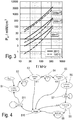
- the FIG. 3 shows dependencies of the specific power loss P V for an exemplary ferrite material of the ferrite core 11 as a function of the operating frequency f in logarithmic plot.
- the dependence is given in several pairs of curves for different magnetizations varying between 50 milli-Tesla (mT) and 200 mT.
- the upper, solid curve indicates the specific power dissipation at 25 ° Celsius, ie approximately room temperature
- the lower dashed curve the specific power dissipation at a temperature of 100 ° Celsius of the ferrite core 11. It can be seen that over the entire frequency range shown for each magnetization used, the losses at lower temperature in the ferrite core 11 are greater than at higher temperature.
- the primary part 1 is "idle", but this would mean an unnecessarily high idle power consumption for the primary part and what is undesirable in view of an unwanted emission of electromagnetic impurities.
- the operation of the primary part 1 may be less harmless if it is subjected to a conductive, e.g. a metallic surface is positioned opposite. The currents induced in the metallic surface can heat these up.
- the primary part should not be operated with a non-matching or defective secondary part.
- FIG. 4 an operating method for a connector for contactless inductive power transmission, which prevents both increased idle power consumption of the primary part 1, as well as an uncontrolled energy transfer to another element as a suitable secondary part 1 '.
- the illustrated operating method for example, with the previously in connection with the Figures 1 and 2 described plug-in device are executed. It is therefore described by way of example with reference to this connector.
- a first step S1 an AC voltage signal with predetermined first parameters is output to the primary coil 10.
- predetermined first parameters for a PWM method are set for this purpose, for example a duty cycle.
- a delay time of, for example, 15 milliseconds may be provided here, which serves for the settling of the system to the settings in step S1.
- Step S2 is optional and may be omitted if the system requires only a negligibly short time to implement changed settings.
- a step S3 the current through the primary coil 1 as an operation amount of the primary coil 10 is measured. Only if the secondary part 1 'is present with respect to the primary part 1, the measured current remains below a predetermined, with the first parameters correlated current limit. Additionally or alternatively, it may be provided, in addition to the current through the primary coil 1 itself, to consider the rate of change of this current.
- a DC link capacitor is usually provided at the rectified voltage, the charging of which, after the setting of an AC voltage signal with the predetermined first parameters, leads to a current change of the current through the primary coil 1 with a characteristic time characteristic. It can thus be determined both via the absolute value of the current and via its rate of change in step S3, whether a secondary part 1 'faces the primary part 1.
- the method branches to a step S10 in which the primary coil 10 is no longer energized, in other words, no energy transfer takes place.
- the method persists in a step S11 for a relatively long delay time, which is 0.5 seconds by way of example here. After this delay time, the method is continued again with step S1, in which again a first amplitude is applied to the primary coil 10.
- step S11 whose duration corresponds approximately to the delay time of step S11, the system thus attempts to establish an energy transfer (polling method).
- a condenser present on the secondary side is discharged via a discharge mechanism in the time of step 11, so that when the method is restarted, it starts with step S1 under the same initial conditions. This is advantageous in particular for the step S3 and the checking of the current or current change values taking place there.
- a current sink can be present on the secondary side, which is switched off after the coupling of primary part 1 and secondary part 1 '(see step S9) in order to reduce the power consumption.
- step S3 If it is determined in step S3 that the measured current is below the limit value and / or shows the expected time dependence, the method is continued after a further short delay time in step S4 with step S5, in which the height of the voltage at the primary coil 10th is determined as a further farm size. If it is determined in step S5 that the voltage does not satisfy certain predefined requirements, the method in turn branches to step S10. On the other hand, if the voltage is in the predetermined range, the process proceeds to a step S6.
- step S6 the primary coil 10 is supplied with an alternating voltage signal having predetermined second parameters.
- second parameters of the PWM method are set analogously to step S1, again using the duty cycle, for example.
- step S7 which serves to stabilize the system on the changed operating conditions (compare step S2)
- step S8 the voltage applied to the coil is again measured in a subsequent step S8. If this voltage does not satisfy second predetermined voltage criteria which are correlated with the second parameters, the system branches again to step S10. Only if it is determined in step S8 that the second criteria are met, the method is continued with step S9, in which the primary coil 10 is operated for energy transmission.
- step S9 the current through the primary coil 1 and / or through switching elements of the inverter is continuously determined. If the absolute value of the current exceeds a certain limit, the operation is stopped and the process branches to step S10. Too high a load on the secondary side is detected on the primary side. Furthermore, the waveform at the output of the inverter is checked on the basis of the currents. Too large deviations of the waveform from a sinusoid indicate an incorrect secondary side. Also, removal of an otherwise matching secondary part 1 'can be detected. In such a case, the process also branches to step S10.
- the illustrated method has the advantage that an incorrect secondary side is detected on the primary side. There is no feedback from the secondary part 1 'to the primary part 1 necessary to ensure safe operation of the primary part 1.
- the system may be exposed to temperatures in a wide temperature range, for example, between -20 ° C and 100 ° C, due to environmental conditions and / or its own power dissipation.
- the parameters and / or limit values used in the method for example in steps S3 and S8, can be predetermined as a function of temperature in order to ensure a correct process sequence with reliable detection of a correctly operating secondary side at every possible operating temperature.
- a safety mechanism based on a feedback of a secondary part to a primary part can alternatively or additionally be used.
- the connector can be provided to constantly determine the size of the air gap in operation and check.
- the air gap can be determined based on a detuning of the resonant circuit via the resonant frequency, possibly in conjunction with the current flowing in the primary coil. It can be provided that the energy transfer when exceeding a predetermined distance d (see. Fig. 1 ) to prevent.
- this is designed for operation in a liquid medium.
- the housing 2 is sealed in connection with the front panel 3 with respect to this liquid medium.
- a heat insulation, z. B. in the form of a thin air gap between the ferrite core 11 and the front panel 3 is provided to achieve the previously described effect of improving the efficiency by heating the ferrite core 11 even within a rather cooling liquid surrounding medium.
- the transmission over the transmission gap d can be optimized for changed magnetic susceptibilities of the liquid medium.
- the seal between the housing 2 and the front panel 3 advantageously also provides protection against dust and dirt.
Landscapes
- Engineering & Computer Science (AREA)
- Power Engineering (AREA)
- Details Of Connecting Devices For Male And Female Coupling (AREA)
- Near-Field Transmission Systems (AREA)
Description
- Die Erfindung betrifft eine Steckvorrichtung zur kontaktlosen Energieübertragung von einem Primärteil auf ein Sekundärteil, die jeweils mindestens eine Spule aufweisen, die induktiv miteinander koppelbar sind. Die Erfindung betrifft weiterhin ein Betriebsverfahren zum sicheren Betreiben einer solchen Steckvorrichtung.
- Gegenüber Steckverbindern, bei denen eine Energieübertragung über mechanisch zu verbindende bzw. zu trennende Kontaktelemente erfolgt, besitzen kontaktlose Steckvorrichtungen Vorteile bezüglich eines Verschleißes durch eine hohe Zahl von Steckzyklen oder starken Vibrationen. Zudem ist ein Kontaktabbrand bei einem Ein- oder Ausstecken unter elektrischer Last verhindert. Auch die Gefahr des Ausbildens von Lichtbögen beim Trennen von Steckverbindern mit einer hohen Strombelastung ist bei kontaktlosen Steckvorrichtungen nicht gegeben. Schließlich liegt bei der kontaktlosen Übertragung von Energie eine galvanische Trennung zwischen dem Primärteil und dem Sekundärteil vor, die beispielsweise beim Einsatz im medizinischen Bereich gefordert sein kann. Das Fehlen der mechanisch aufwendig ineinander greifenden Kontakte ermöglicht zudem eine Gestaltung der Steckvorrichtung mit möglichst glatten Oberflächen, was die kontaktlosen Steckvorrichtungen geeignet für Anwendungszwecke mit einer erhöhten Anforderung an Sauberkeit/Hygiene prädestiniert, beispielsweise im Lebensmittelbereich.
-
US4942352 beschreibt eine Steckvorrichtung zur kontaktlosen Übertragung von elektrischer Energie. Das Gehäuse ist nicht auf thermische Leitfähigkeit ausgelegt, und der Ferrit-Kern wird nicht Temperatur-optimiert betrieben. Die vom Ferrit-Kern weit entfernte Elektronik-Teile, geben erzeugte Wärme an der Bodenplatte ab. InUS2008/0197956 wird von der Spule erzeugte Wärme in einem Wärme dissipierenden Kühlkörper abgeführt. Spule und Ferrit-Kern werden hierdurch abgekühlt. Elektronische Bauteile (Kondensatoren) weiter entfernt auf einer Platine sind hier nicht an Wärme-Erzeugung beteiligt. Die DruckschriftDE 2 75 27 83 beschreibt eine Steckvorrichtung zur Übertragung von elektrischen Messsignalen, insbesondere im Medizinbereich, bei der in den Stecker eine ringförmige Empfangsspule integriert ist, die mit einer ebenfalls ringförmigen Sendespule in dem Gegenstecker im eingesteckten Zustand induktiv über einen Übertragungsspalt gekoppelt ist. Die Sendespule des Gegensteckers wird mit einer Wechselspannung beaufschlagt, die in der Empfangsspule des Steckers eine Spannung induziert, die nach Gleichrichtung eingesetzt wird, um eine im Stecker vorgesehene Auswerteelektronik für die Messsignale zu betreiben. Über die Auswerteelektronik werden die Messsignale auf eine Lichtquelle aufmoduliert, sodass die Messsignale in Form von Lichtsignalen galvanisch getrennt zum Gegenstecker übertragen werden können. Die angegebene induktive Energieübertragung ist dem Einsatzzweck angepasst nur zur Übertragung von kleinen Leistungen zur Versorgung der Messelektronik und der Lichtquelle zur Signalübertagung geeignet. - Insbesondere die hohe Verschleißfestigkeit macht eine kontaktlose induktive Energieübertragung auch im Automatisierungsbereich interessant, beispielsweise zur Übertragung von Energie an ein Wechselwerkzeug eines Roboters. Hierfür würden jedoch Leistungen benötigt, die über eine Vorrichtung, wie sie in der zuvor genannten Druckschrift beschrieben ist, nicht übertragbar sind.
- Es ist daher Aufgabe der vorliegenden Erfindung, eine Steckvorrichtung der Eingangs genannten Art bereitzustellen, über die auch höhere elektrische Leistungen, bevorzugt im Bereich von einigen zehn Watt bis einigen hundert Watt, kontaktlos effizient und sicher übertragen werden können.
- Diese Aufgabe wird durch eine Steckvorrichtung bzw. ein Betriebsverfahren mit den jeweiligen Merkmalen der unabhängigen Ansprüche 1 und 7 gelöst. Vorteilhafte Ausgestaltungen und Weiterbildungen der Steckvorrichtungen sind in den abhängigen Ansprüchen angegeben.
- Ein Aspekt einer Steckvorrichtung zur kontaktlosen induktiven Energieübertragung von einem Primärteil zu einem Sekundärteil, die jeweils mindestens eine Spule aufweisen, die induktiv miteinander koppelbar sind, zeichnet sich dadurch aus, dass die mindestens eine Spule mit jeweils mindestens einem Ferritkern zusammenwirkt. Der Ferritkern erhöht den magnetischen Fluss durch seine Permeabilität derart, dass auch bei kleinen Baugrößen der Steckvorrichtung und kleinen Übertragungsflächen höhere elektrische Leistungen übertragen werden können. Eine Energieübertragung ist durch den hohen magnetischen Fluss auch dann bereits möglich, wenn das Primär- und das Sekundärteil sich (noch) nicht in einer Position befinden, in der der Abstand zwischen ihnen minimal ist, sondern wenn ein Spalt zwischen ihnen besteht. Die Energieübertragung ist dadurch robust und wenig fehleranfällig, auch bei Vibrationen oder dem Vorliegen anderer mechanischer Einflüsse, die zu einer Abstandsvergrößerung zwischen Primär- und Sekundärteil führen. Auch können z.B. sekundärseitig stromversorgte Führungs- oder Sicherheitsmechanismen bereits in einer Annäherungsphase der beiden Teile aktiviert werden.
- In der Steckvorrichtung ist in dem Primärteil zumindest ein Wechselrichter mit elektronischen Komponenten integral mit der Spule und dem Ferritkern in einem Gehäuse angeordnet. Ebenfalls ist in dem Sekundärteil zumindest ein Gleichrichter mit elektronischen Komponenten integral mit der Spule und dem Ferritkern in einem Gehäuse angeordnet. Auf diese Weise entsteht eine Steckvorrichtung, die ähnlich einfach wie eine kontaktbehaftete Steckvorrichtung beispielsweise in einem Kabel zur Energieübertragung angeordnet werden kann.
- In der Ausgestaltung der Steckvorrichtung stehen die jeweiligen elektronischen Komponenten in thermischen Kontakt mit dem jeweiligen Ferritkern. Bevorzugt sind die elektronischen Komponenten im Primär- bzw. Sekundärteil jeweils auf einer Platine angeordnet, die über ein wärmeübertragendes Medium mit dem Ferritkern thermisch gekoppelt ist. Durch die thermische Kopplung wird der jeweilige Ferritkern durch die in den elektronischen Komponenten umgesetzte Verlustleistung erwärmt. Innerhalb eines weiten Bereichs von Betriebsparameteren von Ferritkernen sinken deren Leistungsverluste aufgrund von Ummagnetisierungsprozessen mit steigender Temperatur ab. Der durch die thermische Kopplung erreichte Temperaturanstieg am Ferritkern führt in der Folge zu geringeren Verlusten im Ferritkern, wodurch der Gesamtwirkungsgrad (Übertragungseffizienz) der Steckvorrichtung steigt. In einer weiteren vorteilhaften Ausgestaltung der Steckvorrichtung ist das Innere des Gehäuses gegenüber einem umgebenden Medium, insbesondere gegenüber einer umgebenden Flüssigkeit, abgedichtet. So kann die Steckvorrichtung innerhalb von staubigen, sandigen oder feuchten Umgebungen eingesetzt werden. Auch ist beispielsweise ein Einsatz unter Wasser möglich.
- Eine erfindungsgemäßes Betriebsverfahren für eine Steckvorrichtung zur kontaktlosen induktiven Energieübertragung von einem Primärteil zu einem Sekundärteil zeichnet sich dadurch aus, dass das Primärteil eine Messung von Betriebsgrößen einer zur induktiven Energieübertragung eingesetzten Primärspule vornimmt und abhängig von den gemessenen Betriebsgrößen eine Energieübertragung unterbindet. Auf diese Weise kann von dem Primärteil erkannt werden, wenn entweder gar kein Sekundärteil oder ein nicht passendes oder ein defektes Sekundärteil zur induktiven Kopplung dem Primärteil gegenübersteht. Gerade bei einer Steckvorrichtung mit dem Potential zu Übertragung höherer elektrischer Energie wird so verhindert, dass von dem Primärteil eine Gefährdung ausgeht.
- In einer vorteilhaften Ausgestaltung des Betriebsverfahrens betreffen die Betriebsgrößen eine Spannung an der Primärspule und/oder einen Strom durch die Primärspule, die bzw. der sich ergibt, wenn die Primärspule mit einem Wechselspannungssignal mit vorgegebenen Parametern beaufschlagt wird. Bevorzugt betreffen dabei die vorgegebenen Parameter Größen, insbesondere ein Tastverhältnis, eines PWM-Verfahrens, das zur Erzeugung des Wechselspannungssignals eingesetzt wird.
- Die Erfindung wird nachfolgend anhand von Ausführungsbeispielen mithilfe von vier Figuren näher erläutert. Die Figuren zeigen:
- Fig. 1
- eine erste Schnittansicht einer Steckvorrichtung,
- Fig. 2
- eine weitere Schnittansicht der in
Fig. 1 dargestellten Steckvorrichtung, - Fig. 3
- ein Diagramm zur Darstellung einer spezifischen Verlustleistung in Abhängigkeit der Frequenz bei einem Ferritmaterial unter verschiedenen Betriebsbedingungen und
- Fig. 4
- ein Ablaufdiagramm eines Betriebsverfahrens für eine kontaktlose Steckvorrichtung.
-
Figur 1 zeigt ein schematisches Schnittbild einer anmeldungsgemäßen Steckvorrichtung zur kontaktlosen Energieübertragung von einem Primärteil 1 zu einem Sekundärteil 1'. Elemente, die dem Primärteil 1 zugeordnet sind, im Folgenden auch primärseitige Elemente genannt, tragen in der Figur Bezugszeichen ohne Apostroph. Elemente, die dem Sekundärteil 1' zugeordnet sind, im Folgenden auch sekundärseitige Elemente genannt, tragen Bezugszeichen mit einem entsprechenden Apostroph. Dabei sind primärseitige und sekundärseitige Elemente, die die gleiche oder eine vergleichbare Funktion aufweisen, mit Bezugszeichen mit denselben Zahlen versehen. Wenn im Folgenden nicht explizit auf die Primär- oder Sekundärseite verwiesen wird, werden Bezugszeichen ohne Apostroph verwendet, die sich auf beide Seiten beziehen. - Primärteil 1 und Sekundärteil 1' weisen jeweils ein Gehäuse 2 auf, das aus einem für Steckergehäuse üblichen Material wie Kunststoff, Aluminium oder Edelstahl oder dergleichen gefertigt sein kann. Die Gehäuse 2 sind halbschalenförmig ausgeführt, wobei ihre vordere Seite mit einer Frontplatte 3 verschlossen ist. Im hinteren Bereich, wegweisend von der Frontplatte 3 ist in das Gehäuse 2 eine Kabeldurchführung 4 für ein Anschlusskabel 5 eingebracht.
- Unmittelbar hinter der Frontplatte 3 ist jeweils eine Spule 10 angeordnet, die auf einen Ferritkern 11 gewickelt ist, bzw. auf einen Spulenkörper gewickelt ist, der in den Ferritkern 11 eingelegt ist. Die Spule 10 kann mit einem einzelnen Leiter gewickelt sein. Zur Verringerung des Skin-Effekts ist allerdings eine Verwendung von mehradriger Hochfrequenzlitze bevorzugt.
- Im dargestellten Ausführungsbeispiel ist der Ferritkern 11 primär- und sekundärseitig ein runder Topfkern mit einem äußeren Rand 12 und einem dazu konzentrischen inneren Dom 13. Ein solcher Kern wird auch als (zylindersymmetrischer) E-Kern bezeichnet. Dabei sind die Querschnitte des äußeren Rands 12 und des inneren Doms 13 bevorzugt näherungsweise gleich groß, um eine homogene magnetische Flussdichte unter Berücksichtigung der unterschiedlichen Streufelder im Ferritkern 11 zu erzielen. Die Verwendung von Ferritkernen mit anderer Geometrie ist ebenfalls möglich. Beispielsweise können quadratische oder rechteckige Kerne mit runden oder quadratischen bzw. rechteckigen Ferritkernen eingesetzt werden. Auch Spulen ohne Spulenkörper, z.B. mit miteinander verklebten Leitern können verwendet werden.
- Zur jeweiligen Frontplatte 3 hin sind die Ferritkerne 11 offen, wohingegen auf der gegenüberliegenden Seite der äußere Rand 12 und der innere Dom 13 über einen Topfboden miteinander verbunden sind. Die Spule 10 ist jeweils in den hier ringförmigen Graben zwischen dem äußeren Rand 12 und dem inneren Dom 13 eingelegt. Ein eventuell noch vorhandener Spalt zwischen dem äußeren und inneren Rand der Spule 10 und dem Ferritkern 11 kann mit einem wärmeleitenden Medium ausgefüllt sein.
- Im Betrieb werden zur kontaktlosen induktiven Energieübertragung das Primärteil 1 und das Sekundärteil 1' mit ihren Frontplatten 3, 3' aufeinander zuweisend in geringem Abstand zu einander gebracht. In der
Figur 1 ist dieser Abstand, der einen Übertragungsspalt bildet, als Übertragungsabstand d eingezeichnet. Der Übertragungsabstand d liegt im Bereich von 0 bis einigen Millimetern oder Zentimetern, abhängig von der Größe, insbesondere dem Durchmesser der Spulen 10 bzw. Ferritkerne 11. Im Betrieb wird die primärseitige Spule 10, nachfolgend auch als Primärspule 10 bezeichnet, mit einem Wechselstrom beaufschlagt. Bevorzugt ist dabei aus der Primärspule 10 und einem Resonanzkondensator ein Resonanzkreis gebildet, dessen Frequenz im Bereich von einigen Kilohertz (kHz) bis einigen hundert kHz liegen, wobei eine Frequenz im Bereich von einigen zehn kHz besonders bevorzugt ist. Der Wechselstrom, mit der die Primärspule 10 beaufschlagt wird, wird von einem Wechselrichter bereitgestellt. Im Wechselrichter kann zur Erzeugung der Wechselspannung dabei beispielsweise ein Pulsweitenmodulationsverfahren (PWM) eingesetzt werden. Der Wechselrichter befindet sich zusammen mit Überwachungs- und Steuereinrichtungen auf einer Platine 20 innerhalb des Gehäuses 2 des Primärteils 1. In der Figur sind beispielhaft auf der Platine 20 elektronische Komponenten 21 eingezeichnet. Zum Schutze des Wechselrichters vor einer Resonanzüberhöhung der Amplitude am Resonanzkreis, gebildet aus dem genannten Resonanzkondensator und der Primärspule 10, wird der Resonanzkreis leicht überresonant, also bei Frequenzen oberhalb der Resonanzfrequenz, betrieben. Bei einer Energieübertragung bedingt die magnetische Kopplung zwischen der Primärspule 10 und sekundärseitigen Spule 10', nachfolgend Sekundärspule 10' genannt, die durch die vorhandenen Ferritkerne 11 und 11' besonders effizient ist. In der Sekundärspule 10'wird eine Spannung induziert, die nach Gleichrichtung, Spannungswandlung - und ggf. Spannungsstabilisierung - als Ausgangsspannung am Anschlusskabel 5' zur Abgabe der übertragenen Energie bereitsteht. Die elektronischen Komponenten auf der Sekundärseite sind ebenfalls auf einer Platine 20' angeordnet, wobei hier wiederum beispielhaft einzelne elektronische Komponenten 21' eingezeichnet sind. Vorteilhaft kann die Sekundärspule einen Mittelabgriff aufweisen, so dass ein Synchrongleichrichter verwendet werden kann. - Die Ferritkerne 11, 11' erlauben eine hohe magnetische Flussdichte, durch die eine effiziente Energieübertragung auch bei kleinem Spulenvolumen möglich ist. Die Übertragung ist dabei relativ tolerant gegenüber einer lateralen Verschiebung des Primärteils 1 und des Sekundärteils 1' gegeneinander möglich. Dieses ist beispielsweise im Automatisierungsbereich von hohem Vorteil, da auf eine hohe Positioniergenauigkeit zur Etablierung einer konventionellen kontaktbehafteten Steckverbindung verzichtet werden kann.
- Bei dem dargestellten Ausführungsbeispiel der
Figur 1 sind keine ineinandergreifenden Führungs- oder Positionierungselemente vorgesehen, die das Primärteil 1 und das Sekundärteil 1' beim Ineinanderstecken lateral zueinander ausrichten würden. Durch das Fehlen solcher Elemente können das Primärteil 1 und das Sekundärteil 1' auch durch eine Lateralbewegung, das heißt eine Bewegung in Richtung der Ausdehnung der Frontplatten 3, 3' in die Betriebsposition gebracht werden bzw. von einander getrennt werden. Dieses erweist sich gerade im Automatisierungsbereich als besonders vorteilhaft, da eine zusätzliche axiale Bewegung von Primär- und Sekundärteil 1,1' aufeinander zu zum Etablieren oder Trennen einer Steckverbindung nicht erforderlich ist. Je nach geplantem Anwendungszweck können in alternativen Ausgestaltungen derartige Führungs- oder Positionierungselemente jedoch auch vorgesehen sein. - Sowohl beim Primärteil 1 als auch beim Sekundärteil 1' sind zwischen dem jeweiligen Ferritkern 11 und der Platine 20 Wärmeleitmatten 14 angeordnet. Insbesondere bei der Primärseite, aber auch bei der Sekundärseite stellen die auf der Platine 20 angeordneten elektronischen Bauteile 21 eine große Verlustquelle im Übertragungsweg dar. Die von diesen Bauelementen 21 erzeugte Verlustwärme wird über die Wärmeleitmatten 14 auf den Ferritkern 11 übertragen. Dadurch wärmt sich der Ferritkern 11 im Betrieb auf eine höhere Betriebstemperatur auf, als dieses ohne die thermische Kopplung an die Platine 20 der Fall wäre. Als Folge davon steigt die Effizienz der Energieübertragung, wie anhand der
Figur 3 ersichtlich ist. Anstelle der Wärmeleitmatten 14 kann beispielsweise auch eine Vergussmasse eingesetzt werden, um die Platine 20 und den Ferritkern 11 thermisch zu koppeln. - Die
Figur 3 zeigt Abhängigkeiten der spezifischen Verlustleistung PV für ein beispielhaftes Ferritmaterial des Ferritkerns 11 in Abhängigkeit der Betriebsfrequenz f in doppelt logarithmischer Auftragung. Die Abhängigkeit ist in mehreren Kurvenpaaren für verschiedene Magnetisierungen, die zwischen 50 Milli-Tesla (mT) und 200 mT variieren, angegeben. Bei jedem Kurvenpaar gibt die obere, durchgezogene Kurve die spezifische Verlustleistung bei 25° Celsius, also ungefähr Raumtemperatur, und die untere, gestrichelte Kurve die spezifische Verlustleistung bei einer Temperatur von 100° Celsius des Ferritkerns 11 an. Es ist zu erkennen, dass über dem gesamten dargestellten Frequenzbereich für jede benutzte Magnetisierung die Verluste bei geringerer Temperatur im Ferritkern 11 größer sind als bei höherer Temperatur. Der zuvor beschriebene Eintrag der Verlustleistung der elektronischen Komponenten als Wärme in den Ferritkern 11 erhöht dessen Temperatur und senkt folglich die Verlustleistung im Ferritkern 11 aufgrund der Ummagnetisierung. Dadurch wird der Gesamtwirkungsgrad des Übertragungssystems verbessert. Dieser Effekt kann sowohl auf der Primärseite als auch auf der Sekundärseite genutzt werden. Gleichzeitig wird der vorhandene Ferritkern 11, 11' durch die thermische Kopplung als Kühlkörper für die Elektronikkomponenten 21, 21' eingesetzt, wodurch sich als zusätzlicher Effekt eine Material- und somit Kosteneinsparung ergibt. - Beim Betrieb der Steckvorrichtung besteht aufgrund der hohen übertragbaren Leistung ein Gefahrenpotential, wenn das Primärteil 1 betrieben wird, ohne dass ein passendes komplementäres Sekundärteil 1' diesem gegenüber angeordnet ist. Im harmlosesten Fall wird das Primärteil 1 "leer betrieben", was jedoch einen unnötig hohen Leerlauf-Energieverbrauch für das Primärteil bedeuten würde und was im Hinblick auf eine unerwünschte Abstrahlung von elektromagnetischen Verunreinigungen ungewünscht ist. Weniger harmlos kann dagegen das Betreiben des Primärteils 1 sein, wenn dieses einer leitenden, z.B. einer metallischen Fläche gegenüber positioniert ist. Die in der metallischen Fläche induzierten Ströme können diese aufheizen. Auch sollte das Primärteil nicht mit einem nicht passenden oder defekten Sekundärteil betrieben werden.
- In
Figur 4 ist ein Betriebsverfahren für eine Steckverbindung zur kontaktlosen induktiven Energieübertragung beschrieben, die sowohl einen erhöhten Leerlauf-Energieverbrauch des Primärteils 1, als auch eine unkontrollierte Energieübertragung in ein anderes Element als ein geeignetes Sekundärteil 1' verhindert. Das dargestellte Betriebsverfahren kann beispielsweise mit der zuvor im Zusammenhang mit denFiguren 1 und 2 beschriebenen Steckvorrichtung ausgeführt werden. Es wird daher beispielhaft mit Verweis auf diese Steckverbindung beschrieben. - In einem ersten Schritt S1 wird ein Wechselspannungssignal mit vorgegebenen ersten Parametern an die Primärspule 10 ausgegeben. Im dargestellten Beispiel werden dazu vorgegebene erste Parameter für ein PWM-Verfahren eingestellt, beispielsweise ein Tastverhältnis.
- Danach kann zunächst in einem Schritt S2 eine Verzögerungszeit von hier beispielhaft 15 Millisekunden vorgesehen sein, die dem Einschwingen des Systems auf die Einstellungen im Schritt S1 dient. Der Schritt S2 ist optional und kann entfallen, wenn das System nur eine vernachlässigbar kurze Zeit benötigt, um geänderte Einstellungen umzusetzen.
- Nach dem Schritt S2 wird in einem Schritt S3 der Strom durch die Primärspule 1 als eine Betriebsgröße der Primärspule 10 gemessen. Nur wenn das Sekundärteil 1' gegenüber dem Primärteil 1 vorhanden ist, bleibt der gemessene Strom unterhalb eines vorgegebenen, mit dem ersten Parametern korrelierten Stromgrenzwerts. Zusätzlich oder alternativ kann vorgesehen sein, neben dem Strom durch die Primärspule 1 selbst, die zeitliche Änderungsrate dieses Stroms zu betrachten. Sekundärseitig ist üblicherweise ein Zwischenkreiskondensator an der gleichgerichteten Spannung vorgesehen, dessen Aufladung nach dem Einstellen eines Wechselspannungssignals mit den vorgegebenen ersten Parametern zu einer Stromänderung des Stroms durch die Primärspule 1 mit einem charakteristischen Zeitverlauf führt. Es kann somit sowohl über den Absolutwert des Stroms als auch über dessen Änderungsrate in dem Schritt S3 ermittelt werden, ob ein Sekundärteil 1' dem Primärteil 1 gegenübersteht.
- Wenn kein Sekundärteil 1' vorhanden ist oder auch wenn eine leitende Fläche dem Primärteil 1 gegenübersteht, übersteigt der gemessene Strom den Grenzwert und/oder seine Änderungsrate zeigt nicht den erwarteten charakteristischen Verlauf. In dem Fall verzweigt das Verfahren zu einem Schritt S10, in dem die Primärspule 10 nicht mehr mit Spannung beaufschlagt wird, mit anderen Worten keine Energieübertragung stattfindet. In diesem Zustand verharrt das Verfahren in einem Schritt S11 für eine relativ lange Verzögerungszeit, die hier beispielhaft bei 0,5 Sekunden liegt. Nach Ablauf dieser Verzögerungszeit wird das Verfahren erneut mit dem Schritt S1 fortgesetzt, in dem wiederum eine erste Amplitude an die Primärspule 10 angelegt wird. In einem Takt, dessen Dauer in etwa der Verzögerungszeit des Schritts S11 entspricht, versucht das System somit eine Energieübertragung zu etablieren (Polling-Verfahren). Es kann vorgesehen sein, dass ein ev. sekundärseitig vorhandener Kondensator über einen Entlademechanismus in der Zeit des Schritts 11 entladen wird, so dass bei erneutem Start des Verfahrens mit dem Schritt S1 unter gleichen Anfangsbedingungen startet. Dieses ist insbesondere für den Schritt S3 und die dort erfolgende Überprüfung der Strom- oder Stromänderungswerte vorteilhaft. Zur Entladung kann sekundärseitig eine Stromsenke vorhanden sein, die nach erfolgter Kopplung von Primärteil 1 und Sekundärteil 1' (vgl. Schritt S9) abgeschaltet wird, um den Stromverbrauch zu reduzieren.
- Wenn im Schritt S3 festgestellt wird, dass der gemessene Strom unterhalb des Grenzwertes liegt und/oder die erwartete Zeitabhängigkeit zeigt, wird das Verfahren nach einer weiteren kurzen Verzögerungszeit im Schritt S4 mit einem Schritt S5 fortgesetzt, in dem die Höhe der Spannung an der Primärspule 10 als eine weitere Betriebsgröße bestimmt wird. Wird im Schritt S5 festgestellt, dass die Spannung bestimmte vorgegebene Vorraussetzungen nicht erfüllt, verzweigt das Verfahren wiederum zum Schritt S10. Liegt die Spannung dagegen im vorgegebenen Bereich, wird das Verfahren mit einem Schritt S6 fortgeführt.
- In dem Schritt S6 wird die Primärspule 10 mit einem Wechselspannungssignal mit vorgegebenen zweiten Parametern beaufschlagt. Im dargestellten Beispiel werden dazu analog zum Schritt S1 zweite Parameter des PWM-Verfahrens eingestellt, wiederum beispielsweise über das Tastverhältnis. Nach einer erneuten, optionalen Verzögerungszeit im Schritt S7, die dem Einschwingen des Systems auf die geänderten Betriebsbedingungen dient (vgl. Schritt S2), wird in einem nachfolgenden Schritt S8 wiederum die an der Spule anliegende Spannung gemessen. Erfüllt diese Spannung zweite vorgegebene Spannungskriterien, die mit den zweiten Parametern korreliert sind, nicht, verzweigt das System abermals zum Schritt S10. Nur wenn im Schritt S8 festgestellt wird, dass auch die zweiten Kriterien erfüllt sind, wird das Verfahren mit einem Schritt S9 fortgeführt, in dem die Primärspule 10 zur Energieübertragung betrieben wird.
- Während des Betriebs des Primärteils 1 im Schritt S9 wird fortlaufend der Strom durch die Primärspule 1 und/oder durch Schaltelemente des Wechselrichters ermittelt. Übersteigt der Absolutwert des Stroms einen bestimmten Grenzwert, wird der Betrieb abgebrochen und das Verfahren verzweigt zu Schritt S10. So wird eine zu hohe Last an der Sekundärseite primärseitig erkannt. Weiterhin wird anhand der Ströme die Kurvenform am Ausgang des Wechselrichters überprüft. Zu große Abweichungen der Kurvenform von einer Sinuskurve deuten auf eine nicht korrekte Sekundärseite hin. Auch ein Entfernen eines ansonsten passenden Sekundärteils 1' kann so detektiert werden. In einem solchen Fall verzweigt das Verfahren ebenfalls zum Schritt S10.
- Das dargestellt Verfahren hat den Vorteil, dass eine nicht korrekte Sekundseite primärseitig erkannt wird. Es ist keine Rückmeldung von dem Sekundärteil 1' an das Primärteil 1 notwendig, um ein sicheres Betreiben des Primärteils 1 zu garantieren. In einer Betriebsumgebung kann das System durch die Umgebungsbedingungen und/oder auch durch eigne Verlustleistung Temperaturen in einem weiten Temperaturbereich, beispielsweise zwischen -20°C und 100 °C, ausgesetzt sein. Die in dem Verfahren, beispielsweise in den Schritten S3 und S8, eingesetzten Parametern und/oder Grenzwerte können temperaturabhängig vorgegeben sein, um bei jeder möglichen Betriebstemperatur einen korrekten Verfahrensablauf mit sicherer Erkennung einer korrekt arbeitenden Sekundärseite sicherzustellen.
- In einer alternativen Ausgestaltung des Steckverbinders ist ein auf einer Rückmeldung eines Sekundärteils an ein Primärteil basierender Sicherheitsmechanismus alternativ oder zusätzlich einsetzbar.
- In einer weiteren alternativen Ausgestaltung des Steckverbinders kann vorgesehen sein, die Größe des Luftspaltes im Betrieb ständig zu ermitteln und zu überprüfen. Der Luftspalt kann anhand einer Verstimmung des Resonanzkreises über die Resonanzfrequenz ggf. in Verbindung mit dem in der Primärspule fließenden Strom ermittelt werden. Es kann vorgesehen sein, die Energieübertragung bei Überschreiten eines vorgegebenen Abstands d (vgl.
Fig. 1 ) zu unterbinden. - Weiterhin ist es möglich, sekundärseitig eine Energiepufferung, z.B. durch einen Kondensator mit hoher Kapazität, vorzusehen, um in der Sekundärseite bei temporärem Spannungsausfall, z.B. innerhalb während eines Werkzeugwechsels, einen Betrieb oder Notbetrieb aufrechtzuhalten.
- In einer vorteilhaften Ausgestaltung der Steckvorrichtung ist diese für den Betrieb in einem flüssigen Medium ausgelegt. Dazu ist zum Einen das Gehäuse 2 in Verbindung mit der Frontplatte 3 gegenüber diesem flüssigen Medium abgedichtet. Zum Anderen kann zusätzlich eine Wärmeisolierung, z. B. in Form eines dünnen Luftspalts zwischen dem Ferritkern 11 und der Frontplatte 3 vorgesehen sein, um den zuvor beschriebenen Effekt der Effizienzverbesserung durch Erwärmung des Ferritkerns 11 auch innerhalb eines eher kühlenden flüssigen umgebenden Mediums zu erreichen. Zudem kann die Übertragung über den Übertragungsspalt d auf geänderte magnetische Suszeptibilitäten des flüssigen Mediums optimiert werden. Die Abdichtung zwischen dem Gehäuse 2 und der Frontplatte 3 bietet vorteilhafterweise auch einen Schutz vor Staub und Schmutz.
-
- 1
- Primärteil
- 1'
- Sekundärteil
- 2,2'
- Gehäuse
- 3,3'
- Abdeckplatte
- 4, 4'
- Anschlusskabel
- 5, 5'
- Kabeldurchführung
- 10
- Primärspule
- 10'
- Sekundärspule
- 11, 11'
- Ferritkern
- 12, 12'
- äußerer Rand
- 13, 13'
- innerer Dom
- 14, 14'
- Wärmeleitmatte
- 20, 20'
- Platine
- 21, 21'
- elektronische Bauelemente
Claims (9)
- Steckvorrichtung geeignet zur kontaktlosen induktiven Energieübertragung von einem Primärteil (1) zu einem Sekundärteil (1'), die Steckvorrichtung diese Teile beinhaltend, die jeweils mindestens eine Spule (10, 10') aufweisen, die induktiv miteinander koppelbar sind, wobei die mindestens eine Spule (10, 10') mit jeweils mindestens einem Ferritkern (11, 11') zusammenwirkt, wobei in dem Primärteil (1) zumindest ein Wechselrichter mit elektronischen Komponenten (21) integral mit der Spule (10) und dem Ferritkern (11) in einem Gehäuse (2) angeordnet ist und/oder in dem Sekundärteil (1') zumindest ein Gleichrichter mit elektronischen Komponenten (21') integral mit der Spule (10') und dem Ferritkern (11') in einem Gehäuse (2') angeordnet ist, dadurch gekennzeichnet, dass die jeweiligen elektronischen Komponenten (21, 21') in thermischem Kontakt mit dem jeweiligen Ferritkern (11, 11') stehen, wobei der jeweilige Ferritkern (11, 11') im Betrieb durch die in den elektronischen Komponenten umgesetzte Verlustleistung erwärmbar ist.
- Steckvorrichtung nach Anspruch 1, bei der der Ferritkern (11, 11') ein Topfkern mit äußerem Rand (12, 12') und innerem Dom (13, 13') ist.
- Steckvorrichtung nach Anspruch 1 oder 2, bei der die elektronischen Komponenten (21, 21') im Primär- bzw. Sekundärteil (1, 1') jeweils auf einer Platine (20, 20') angeordnet sind, die über ein wärmeübertragendes Medium mit dem Ferritkern (11, 11') thermisch gekoppelt ist.
- Steckvorrichtung nach Anspruch 3, bei der das wärmeübertragendes Medium eine Wärmeleitmatte (14, 14') ist.
- Steckvorrichtung nach einem der Ansprüche 1 bis 4, bei der ein Wärmeübergang von der jeweiligen Spule (10, 10') auf den zugeordneten Ferritkern (11, 11') durch ein wärmeübertragendes Medium erhöht ist.
- Steckvorrichtung nach einem der Ansprüche 1 bis 5, bei der das Innere des Gehäuses (2, 2') gegenüber einem umgebenden Medium, insbesondere gegenüber einer umgebenden Flüssigkeit, abgedichtet ist.
- Betriebsverfahren für eine Steckvorrichtung zur kontaktlosen induktiven Energieübertragung von einem Primärteil (1) zu einem Sekundärteil (1') gemäß einem der Ansprüche 1 bis 6, bei dem das Primärteil (1) eine Messung von Betriebsgrößen einer zur induktiven Energieübertragung eingesetzten Primärspule (10) vornimmt und abhängig von den gemessenen Betriebsgrößen eine Energieübertragung unterbindet.
- Betriebsverfahren nach Anspruch 7, bei dem die Betriebsgrößen eine Spannung an der Primärspule (10) und/oder einen Strom durch die Primärspule (10) betreffen, die bzw. der sich ergibt, wenn die Primärspule (10) mit einem Wechselspannungssignal mit vorgegebenen Parametern beaufschlagt wird.
- Betriebsverfahren nach Anspruch 8, bei dem die vorgegebenen Parameter Größen, insbesondere ein Tastverhältnis, eines PWM-Verfahrens sind, das zur Erzeugung des Wechselspannungssignals eingesetzt wird.
Applications Claiming Priority (2)
| Application Number | Priority Date | Filing Date | Title |
|---|---|---|---|
| DE102011056265A DE102011056265A1 (de) | 2011-12-12 | 2011-12-12 | Steckvorrichtung zur kontaktlosen induktiven Energieübertragung und Betriebsverfahren für eine solche Steckvorrichtung |
| PCT/EP2012/075189 WO2013087676A2 (de) | 2011-12-12 | 2012-12-12 | Steckvorrichtung zur kontaktlosen induktiven energieübertragung und betriebsverfahren für eine solche steckvorrichtung |
Publications (2)
| Publication Number | Publication Date |
|---|---|
| EP2791950A2 EP2791950A2 (de) | 2014-10-22 |
| EP2791950B1 true EP2791950B1 (de) | 2019-01-23 |
Family
ID=47504874
Family Applications (1)
| Application Number | Title | Priority Date | Filing Date |
|---|---|---|---|
| EP12810162.3A Active EP2791950B1 (de) | 2011-12-12 | 2012-12-12 | Steckvorrichtung zur kontaktlosen induktiven energieübertragung und betriebsverfahren für eine solche steckvorrichtung |
Country Status (6)
| Country | Link |
|---|---|
| US (1) | US9715963B2 (de) |
| EP (1) | EP2791950B1 (de) |
| CN (1) | CN103988269B (de) |
| DE (1) | DE102011056265A1 (de) |
| ES (1) | ES2713575T3 (de) |
| WO (1) | WO2013087676A2 (de) |
Cited By (1)
| Publication number | Priority date | Publication date | Assignee | Title |
|---|---|---|---|---|
| US11214156B2 (en) | 2018-11-05 | 2022-01-04 | Mahle International Gmbh | Inductive charging device |
Families Citing this family (10)
| Publication number | Priority date | Publication date | Assignee | Title |
|---|---|---|---|---|
| DE102014216783B4 (de) | 2014-08-22 | 2017-02-16 | Leoni Kabel Holding Gmbh | Steckverbindung und Steckverbinder für eine solche |
| DE102014019825B3 (de) | 2014-08-22 | 2018-09-06 | Leoni Kabel Holding Gmbh | Steckverbindung und Steckverbinder für eine solche |
| DE102015113723A1 (de) | 2015-04-09 | 2016-10-13 | Weidmüller Interface GmbH & Co. KG | Vorrichtung zur kontaktlosen induktiven Energieübertragung und Betriebsverfahren für eine derartige Vorrichtung |
| DE102015216060A1 (de) * | 2015-08-21 | 2017-02-23 | Mts Maschinentechnik Schrode Ag | Verbindungsanordnung |
| US20170104367A1 (en) * | 2015-10-12 | 2017-04-13 | Micah Laughmiller | Systems and methods for an electrical power connector |
| DE102017101891A1 (de) | 2016-10-10 | 2018-04-12 | Weidmüller Interface GmbH & Co. KG | Vorrichtung zur kontaktlosen induktiven Energieübertragung und Betriebsverfahren für eine derartige Vorrichtung |
| EP3930207B1 (de) * | 2017-01-11 | 2024-03-20 | Canon Kabushiki Kaisha | Drahtloskommunikationssystem, kommunikationsvorrichtung und kommunikationsverfahren |
| DE102017108302A1 (de) | 2017-04-19 | 2018-10-25 | Weidmüller Interface GmbH & Co. KG | Vorrichtung zur kontaktlosen induktiven Energieübertragung und Verfahren zum Betreiben der Vorrichtung |
| DE102018120779B3 (de) | 2018-08-24 | 2019-12-12 | Phoenix Contact Gmbh & Co. Kg | Kontaktloses PoE-Verbindungssystem |
| DE102023124791B3 (de) | 2023-09-14 | 2025-03-20 | Dr. Ing. H.C. F. Porsche Aktiengesellschaft | Leistungselektronische Schaltung und Kraftfahrzeug |
Family Cites Families (15)
| Publication number | Priority date | Publication date | Assignee | Title |
|---|---|---|---|---|
| DE2752783C2 (de) | 1977-11-25 | 1979-08-30 | Siemens Ag, 1000 Berlin Und 8000 Muenchen | Gerät zum Erfassen und Verarbeiten von elektrischen Signalen |
| JPH0747957Y2 (ja) * | 1987-03-31 | 1995-11-01 | トツパン・ム−ア株式会社 | 非接触式電力供給装置 |
| DE4236286A1 (de) * | 1992-10-28 | 1994-05-05 | Daimler Benz Ag | Verfahren und Anordnung zum automatischen berührungslosen Laden |
| JP3363341B2 (ja) * | 1997-03-26 | 2003-01-08 | 松下電工株式会社 | 非接触電力伝達装置 |
| DE19719730C1 (de) * | 1997-05-09 | 1998-10-22 | Bartec Mestechnik Und Sensorik | Steckverbindung |
| IE20000731A1 (en) * | 1999-09-13 | 2001-07-11 | Commergy Technologies Ltd | A printed circuit board assembly |
| JP2003142327A (ja) * | 2001-10-31 | 2003-05-16 | Furukawa Electric Co Ltd:The | 非接触給電装置 |
| DE10220450A1 (de) * | 2002-05-07 | 2003-11-20 | Conducta Endress & Hauser | Kontaktloses Verbindungskabel |
| JP4222115B2 (ja) * | 2003-06-13 | 2009-02-12 | セイコーエプソン株式会社 | 非接触電力伝送装置 |
| CN1674405A (zh) * | 2004-06-11 | 2005-09-28 | 深圳市丕希软件科技有限公司 | 电器的非接触式供电方法及其装置 |
| EP1686597B1 (de) * | 2005-01-04 | 2016-10-05 | ASM Assembly Systems GmbH & Co. KG | Vorrichtung zur induktiven Energieübertragung zwischen einem Bestückautomaten und einer Zuführeinrichtung für Bauelemente, Zuführeinrichtung und Bestückautomat. |
| US7750783B2 (en) * | 2007-02-20 | 2010-07-06 | Seiko Epson Corporation | Electronic instrument including a coil unit |
| JP4281837B2 (ja) * | 2007-02-20 | 2009-06-17 | セイコーエプソン株式会社 | コイルユニットおよびその製造方法ならびに電子機器 |
| DE102009019994B4 (de) * | 2008-05-19 | 2020-08-13 | Airbus Operations Gmbh | Flugzeug mit Hybrid Transmittern zur kontaktlosen Energie-und Datenübertragung |
| CN201947065U (zh) * | 2010-10-18 | 2011-08-24 | 陈庭勋 | 贴近式无线输电装置结构 |
-
2011
- 2011-12-12 DE DE102011056265A patent/DE102011056265A1/de not_active Withdrawn
-
2012
- 2012-12-12 WO PCT/EP2012/075189 patent/WO2013087676A2/de not_active Ceased
- 2012-12-12 CN CN201280061386.6A patent/CN103988269B/zh active Active
- 2012-12-12 EP EP12810162.3A patent/EP2791950B1/de active Active
- 2012-12-12 US US14/360,646 patent/US9715963B2/en active Active
- 2012-12-12 ES ES12810162T patent/ES2713575T3/es active Active
Cited By (1)
| Publication number | Priority date | Publication date | Assignee | Title |
|---|---|---|---|---|
| US11214156B2 (en) | 2018-11-05 | 2022-01-04 | Mahle International Gmbh | Inductive charging device |
Also Published As
| Publication number | Publication date |
|---|---|
| ES2713575T3 (es) | 2019-05-22 |
| CN103988269B (zh) | 2018-03-27 |
| EP2791950A2 (de) | 2014-10-22 |
| WO2013087676A2 (de) | 2013-06-20 |
| US20140327322A1 (en) | 2014-11-06 |
| CN103988269A (zh) | 2014-08-13 |
| US9715963B2 (en) | 2017-07-25 |
| WO2013087676A3 (de) | 2013-08-22 |
| DE102011056265A1 (de) | 2013-06-13 |
Similar Documents
| Publication | Publication Date | Title |
|---|---|---|
| EP2791950A2 (de) | Steckvorrichtung zur kontaktlosen induktiven energieübertragung und betriebsverfahren für eine solche steckvorrichtung | |
| EP1275208B1 (de) | Anordnung zur kontaktlosen übertragung elektrischer signale bzw. energie | |
| DE102015113723A1 (de) | Vorrichtung zur kontaktlosen induktiven Energieübertragung und Betriebsverfahren für eine derartige Vorrichtung | |
| EP3523816B1 (de) | Vorrichtung zur kontaktlosen induktiven energieübertragung und betriebsverfahren für eine derartige vorrichtung | |
| DE102011050655A1 (de) | Verfahren zur Erkennung eines elektrisch leitfähigen Fremdkörpers und Vorrichtung zur induktiven Übertragung elektrischer Energie | |
| WO2013189530A1 (de) | Detektionsspulen-baueinheit, energieübertragungsspulen-baueinheit und detektionssystem zum erkennen von elektrisch leitfähigen fremdkörpern | |
| DE10026175A1 (de) | Induktiver Bus | |
| DE112013006773T5 (de) | Vorrichtung für high-side Transistor-Brückentreiber | |
| EP2067231A1 (de) | System und verfahren zur berührungslosen energieübertragung | |
| DE202011050264U1 (de) | Vorrichtung zur induktiven Übertragung elektrischer Energie | |
| DE112010005440B4 (de) | Ansteuerschaltung für elektromagnetischen Betätigungsmechanismus | |
| WO2013149781A2 (de) | Drahtlose energieübertragung | |
| DE112013004161T5 (de) | Kontaktlose Leistungsempfangsvorrichtung und kontaktloses Leistungsversorgungssystem | |
| DE102017214603A1 (de) | Verfahren und Vorrichtung zur Detektion von elektrisch leitfähigen Fremdkörpern bei der induktiven Energieübertragung | |
| WO2017202569A2 (de) | Primärgetaktetes schaltnetzeil | |
| DE102009011125B4 (de) | System und Verfahren zur berührungslosen Energieübertragung | |
| EP3613126B1 (de) | Vorrichtung zur kontaktlosen induktiven energieübertragung und verfahren zum betreiben der vorrichtung | |
| EP3221180B1 (de) | System zum induktiven übertragen von elektrischer leistung | |
| DE102024107348A1 (de) | Steckverbindersystem für das Verbinden und Trennen von Steckverbindungen unter Last | |
| DE102018214783B4 (de) | Vorrichtung zur induktiven Übertragung elektrischer Energie von einem Primärkreis zu einem Sekundärkreis und Verfahren zum Betreiben einer solchen Vorrichtung | |
| DE102024123091A1 (de) | Vorrichtung und system zur drahtlosen leistungsübertragung | |
| DE102015008983A1 (de) | System zur kontaktlosen und/oder induktiven Energieübertragung an eine Last und Verfahren zur Dimensionierung eines Vierpols bei einem System | |
| DE112024001166T5 (de) | Kontaktlose leistungseinspeisungseinrichtung | |
| DE102015009073B4 (de) | Anordnung zur induktiven Übertragung elektrischer Energie von einem stationär angeordneten Primärleiter an eine relativ dazu bewegbare Vorrichtung und Verfahren zum Betreiben der Anordnung | |
| DE102023100064A1 (de) | Vorrichtung zur kontaktlosen Energie- und Datenübertragung |
Legal Events
| Date | Code | Title | Description |
|---|---|---|---|
| PUAI | Public reference made under article 153(3) epc to a published international application that has entered the european phase |
Free format text: ORIGINAL CODE: 0009012 |
|
| 17P | Request for examination filed |
Effective date: 20140624 |
|
| AK | Designated contracting states |
Kind code of ref document: A2 Designated state(s): AL AT BE BG CH CY CZ DE DK EE ES FI FR GB GR HR HU IE IS IT LI LT LU LV MC MK MT NL NO PL PT RO RS SE SI SK SM TR |
|
| DAX | Request for extension of the european patent (deleted) | ||
| GRAP | Despatch of communication of intention to grant a patent |
Free format text: ORIGINAL CODE: EPIDOSNIGR1 |
|
| STAA | Information on the status of an ep patent application or granted ep patent |
Free format text: STATUS: GRANT OF PATENT IS INTENDED |
|
| INTG | Intention to grant announced |
Effective date: 20180716 |
|
| GRAS | Grant fee paid |
Free format text: ORIGINAL CODE: EPIDOSNIGR3 |
|
| GRAA | (expected) grant |
Free format text: ORIGINAL CODE: 0009210 |
|
| STAA | Information on the status of an ep patent application or granted ep patent |
Free format text: STATUS: THE PATENT HAS BEEN GRANTED |
|
| AK | Designated contracting states |
Kind code of ref document: B1 Designated state(s): AL AT BE BG CH CY CZ DE DK EE ES FI FR GB GR HR HU IE IS IT LI LT LU LV MC MK MT NL NO PL PT RO RS SE SI SK SM TR |
|
| REG | Reference to a national code |
Ref country code: GB Ref legal event code: FG4D Free format text: NOT ENGLISH |
|
| REG | Reference to a national code |
Ref country code: CH Ref legal event code: EP |
|
| REG | Reference to a national code |
Ref country code: AT Ref legal event code: REF Ref document number: 1092111 Country of ref document: AT Kind code of ref document: T Effective date: 20190215 |
|
| REG | Reference to a national code |
Ref country code: IE Ref legal event code: FG4D Free format text: LANGUAGE OF EP DOCUMENT: GERMAN |
|
| REG | Reference to a national code |
Ref country code: DE Ref legal event code: R096 Ref document number: 502012014217 Country of ref document: DE |
|
| REG | Reference to a national code |
Ref country code: ES Ref legal event code: FG2A Ref document number: 2713575 Country of ref document: ES Kind code of ref document: T3 Effective date: 20190522 |
|
| REG | Reference to a national code |
Ref country code: NL Ref legal event code: MP Effective date: 20190123 |
|
| PG25 | Lapsed in a contracting state [announced via postgrant information from national office to epo] |
Ref country code: NL Free format text: LAPSE BECAUSE OF FAILURE TO SUBMIT A TRANSLATION OF THE DESCRIPTION OR TO PAY THE FEE WITHIN THE PRESCRIBED TIME-LIMIT Effective date: 20190123 |
|
| PG25 | Lapsed in a contracting state [announced via postgrant information from national office to epo] |
Ref country code: PT Free format text: LAPSE BECAUSE OF FAILURE TO SUBMIT A TRANSLATION OF THE DESCRIPTION OR TO PAY THE FEE WITHIN THE PRESCRIBED TIME-LIMIT Effective date: 20190523 Ref country code: SE Free format text: LAPSE BECAUSE OF FAILURE TO SUBMIT A TRANSLATION OF THE DESCRIPTION OR TO PAY THE FEE WITHIN THE PRESCRIBED TIME-LIMIT Effective date: 20190123 Ref country code: NO Free format text: LAPSE BECAUSE OF FAILURE TO SUBMIT A TRANSLATION OF THE DESCRIPTION OR TO PAY THE FEE WITHIN THE PRESCRIBED TIME-LIMIT Effective date: 20190423 Ref country code: FI Free format text: LAPSE BECAUSE OF FAILURE TO SUBMIT A TRANSLATION OF THE DESCRIPTION OR TO PAY THE FEE WITHIN THE PRESCRIBED TIME-LIMIT Effective date: 20190123 Ref country code: LT Free format text: LAPSE BECAUSE OF FAILURE TO SUBMIT A TRANSLATION OF THE DESCRIPTION OR TO PAY THE FEE WITHIN THE PRESCRIBED TIME-LIMIT Effective date: 20190123 Ref country code: PL Free format text: LAPSE BECAUSE OF FAILURE TO SUBMIT A TRANSLATION OF THE DESCRIPTION OR TO PAY THE FEE WITHIN THE PRESCRIBED TIME-LIMIT Effective date: 20190123 |
|
| PG25 | Lapsed in a contracting state [announced via postgrant information from national office to epo] |
Ref country code: BG Free format text: LAPSE BECAUSE OF FAILURE TO SUBMIT A TRANSLATION OF THE DESCRIPTION OR TO PAY THE FEE WITHIN THE PRESCRIBED TIME-LIMIT Effective date: 20190423 Ref country code: IS Free format text: LAPSE BECAUSE OF FAILURE TO SUBMIT A TRANSLATION OF THE DESCRIPTION OR TO PAY THE FEE WITHIN THE PRESCRIBED TIME-LIMIT Effective date: 20190523 Ref country code: GR Free format text: LAPSE BECAUSE OF FAILURE TO SUBMIT A TRANSLATION OF THE DESCRIPTION OR TO PAY THE FEE WITHIN THE PRESCRIBED TIME-LIMIT Effective date: 20190424 Ref country code: HR Free format text: LAPSE BECAUSE OF FAILURE TO SUBMIT A TRANSLATION OF THE DESCRIPTION OR TO PAY THE FEE WITHIN THE PRESCRIBED TIME-LIMIT Effective date: 20190123 Ref country code: LV Free format text: LAPSE BECAUSE OF FAILURE TO SUBMIT A TRANSLATION OF THE DESCRIPTION OR TO PAY THE FEE WITHIN THE PRESCRIBED TIME-LIMIT Effective date: 20190123 Ref country code: RS Free format text: LAPSE BECAUSE OF FAILURE TO SUBMIT A TRANSLATION OF THE DESCRIPTION OR TO PAY THE FEE WITHIN THE PRESCRIBED TIME-LIMIT Effective date: 20190123 |
|
| REG | Reference to a national code |
Ref country code: DE Ref legal event code: R097 Ref document number: 502012014217 Country of ref document: DE |
|
| PG25 | Lapsed in a contracting state [announced via postgrant information from national office to epo] |
Ref country code: RO Free format text: LAPSE BECAUSE OF FAILURE TO SUBMIT A TRANSLATION OF THE DESCRIPTION OR TO PAY THE FEE WITHIN THE PRESCRIBED TIME-LIMIT Effective date: 20190123 Ref country code: SK Free format text: LAPSE BECAUSE OF FAILURE TO SUBMIT A TRANSLATION OF THE DESCRIPTION OR TO PAY THE FEE WITHIN THE PRESCRIBED TIME-LIMIT Effective date: 20190123 Ref country code: CZ Free format text: LAPSE BECAUSE OF FAILURE TO SUBMIT A TRANSLATION OF THE DESCRIPTION OR TO PAY THE FEE WITHIN THE PRESCRIBED TIME-LIMIT Effective date: 20190123 Ref country code: DK Free format text: LAPSE BECAUSE OF FAILURE TO SUBMIT A TRANSLATION OF THE DESCRIPTION OR TO PAY THE FEE WITHIN THE PRESCRIBED TIME-LIMIT Effective date: 20190123 Ref country code: EE Free format text: LAPSE BECAUSE OF FAILURE TO SUBMIT A TRANSLATION OF THE DESCRIPTION OR TO PAY THE FEE WITHIN THE PRESCRIBED TIME-LIMIT Effective date: 20190123 Ref country code: AL Free format text: LAPSE BECAUSE OF FAILURE TO SUBMIT A TRANSLATION OF THE DESCRIPTION OR TO PAY THE FEE WITHIN THE PRESCRIBED TIME-LIMIT Effective date: 20190123 |
|
| PG25 | Lapsed in a contracting state [announced via postgrant information from national office to epo] |
Ref country code: SM Free format text: LAPSE BECAUSE OF FAILURE TO SUBMIT A TRANSLATION OF THE DESCRIPTION OR TO PAY THE FEE WITHIN THE PRESCRIBED TIME-LIMIT Effective date: 20190123 |
|
| PLBE | No opposition filed within time limit |
Free format text: ORIGINAL CODE: 0009261 |
|
| STAA | Information on the status of an ep patent application or granted ep patent |
Free format text: STATUS: NO OPPOSITION FILED WITHIN TIME LIMIT |
|
| 26N | No opposition filed |
Effective date: 20191024 |
|
| PG25 | Lapsed in a contracting state [announced via postgrant information from national office to epo] |
Ref country code: SI Free format text: LAPSE BECAUSE OF FAILURE TO SUBMIT A TRANSLATION OF THE DESCRIPTION OR TO PAY THE FEE WITHIN THE PRESCRIBED TIME-LIMIT Effective date: 20190123 |
|
| PG25 | Lapsed in a contracting state [announced via postgrant information from national office to epo] |
Ref country code: TR Free format text: LAPSE BECAUSE OF FAILURE TO SUBMIT A TRANSLATION OF THE DESCRIPTION OR TO PAY THE FEE WITHIN THE PRESCRIBED TIME-LIMIT Effective date: 20190123 |
|
| REG | Reference to a national code |
Ref country code: CH Ref legal event code: PL |
|
| REG | Reference to a national code |
Ref country code: BE Ref legal event code: MM Effective date: 20191231 |
|
| PG25 | Lapsed in a contracting state [announced via postgrant information from national office to epo] |
Ref country code: MC Free format text: LAPSE BECAUSE OF FAILURE TO SUBMIT A TRANSLATION OF THE DESCRIPTION OR TO PAY THE FEE WITHIN THE PRESCRIBED TIME-LIMIT Effective date: 20190123 |
|
| GBPC | Gb: european patent ceased through non-payment of renewal fee |
Effective date: 20191212 |
|
| PG25 | Lapsed in a contracting state [announced via postgrant information from national office to epo] |
Ref country code: LU Free format text: LAPSE BECAUSE OF NON-PAYMENT OF DUE FEES Effective date: 20191212 Ref country code: IE Free format text: LAPSE BECAUSE OF NON-PAYMENT OF DUE FEES Effective date: 20191212 Ref country code: GB Free format text: LAPSE BECAUSE OF NON-PAYMENT OF DUE FEES Effective date: 20191212 |
|
| PG25 | Lapsed in a contracting state [announced via postgrant information from national office to epo] |
Ref country code: CH Free format text: LAPSE BECAUSE OF NON-PAYMENT OF DUE FEES Effective date: 20191231 Ref country code: LI Free format text: LAPSE BECAUSE OF NON-PAYMENT OF DUE FEES Effective date: 20191231 Ref country code: BE Free format text: LAPSE BECAUSE OF NON-PAYMENT OF DUE FEES Effective date: 20191231 |
|
| REG | Reference to a national code |
Ref country code: AT Ref legal event code: MM01 Ref document number: 1092111 Country of ref document: AT Kind code of ref document: T Effective date: 20191212 |
|
| PG25 | Lapsed in a contracting state [announced via postgrant information from national office to epo] |
Ref country code: AT Free format text: LAPSE BECAUSE OF NON-PAYMENT OF DUE FEES Effective date: 20191212 Ref country code: CY Free format text: LAPSE BECAUSE OF FAILURE TO SUBMIT A TRANSLATION OF THE DESCRIPTION OR TO PAY THE FEE WITHIN THE PRESCRIBED TIME-LIMIT Effective date: 20190123 |
|
| PG25 | Lapsed in a contracting state [announced via postgrant information from national office to epo] |
Ref country code: HU Free format text: LAPSE BECAUSE OF FAILURE TO SUBMIT A TRANSLATION OF THE DESCRIPTION OR TO PAY THE FEE WITHIN THE PRESCRIBED TIME-LIMIT; INVALID AB INITIO Effective date: 20121212 Ref country code: MT Free format text: LAPSE BECAUSE OF FAILURE TO SUBMIT A TRANSLATION OF THE DESCRIPTION OR TO PAY THE FEE WITHIN THE PRESCRIBED TIME-LIMIT Effective date: 20190123 |
|
| PG25 | Lapsed in a contracting state [announced via postgrant information from national office to epo] |
Ref country code: MK Free format text: LAPSE BECAUSE OF FAILURE TO SUBMIT A TRANSLATION OF THE DESCRIPTION OR TO PAY THE FEE WITHIN THE PRESCRIBED TIME-LIMIT Effective date: 20190123 |
|
| P01 | Opt-out of the competence of the unified patent court (upc) registered |
Effective date: 20230521 |
|
| PGFP | Annual fee paid to national office [announced via postgrant information from national office to epo] |
Ref country code: DE Payment date: 20251211 Year of fee payment: 14 |
|
| PGFP | Annual fee paid to national office [announced via postgrant information from national office to epo] |
Ref country code: IT Payment date: 20251223 Year of fee payment: 14 |
|
| PGFP | Annual fee paid to national office [announced via postgrant information from national office to epo] |
Ref country code: FR Payment date: 20251223 Year of fee payment: 14 |
|
| PGFP | Annual fee paid to national office [announced via postgrant information from national office to epo] |
Ref country code: ES Payment date: 20260130 Year of fee payment: 14 |