EP2791500B1 - Windturbinenrotorblatt und produktionsverfahren - Google Patents
Windturbinenrotorblatt und produktionsverfahren Download PDFInfo
- Publication number
- EP2791500B1 EP2791500B1 EP12805931.8A EP12805931A EP2791500B1 EP 2791500 B1 EP2791500 B1 EP 2791500B1 EP 12805931 A EP12805931 A EP 12805931A EP 2791500 B1 EP2791500 B1 EP 2791500B1
- Authority
- EP
- European Patent Office
- Prior art keywords
- wind turbine
- turbine blade
- stack
- elongate
- shell
- Prior art date
- Legal status (The legal status is an assumption and is not a legal conclusion. Google has not performed a legal analysis and makes no representation as to the accuracy of the status listed.)
- Revoked
Links
- 238000004519 manufacturing process Methods 0.000 title claims description 19
- 230000003014 reinforcing effect Effects 0.000 claims description 215
- 239000011162 core material Substances 0.000 claims description 32
- 229920005989 resin Polymers 0.000 claims description 23
- 239000011347 resin Substances 0.000 claims description 23
- 239000002131 composite material Substances 0.000 claims description 22
- 239000000835 fiber Substances 0.000 claims description 19
- 238000010276 construction Methods 0.000 claims description 8
- 239000000463 material Substances 0.000 claims description 8
- OKTJSMMVPCPJKN-UHFFFAOYSA-N Carbon Chemical compound [C] OKTJSMMVPCPJKN-UHFFFAOYSA-N 0.000 claims description 4
- 229910052799 carbon Inorganic materials 0.000 claims description 4
- 239000003365 glass fiber Substances 0.000 claims description 4
- 229920002522 Wood fibre Polymers 0.000 claims description 2
- 229920003235 aromatic polyamide Polymers 0.000 claims description 2
- 239000010410 layer Substances 0.000 description 83
- 238000000034 method Methods 0.000 description 21
- 239000004616 structural foam Substances 0.000 description 11
- 239000011152 fibreglass Substances 0.000 description 9
- 230000008569 process Effects 0.000 description 9
- 239000000853 adhesive Substances 0.000 description 8
- 230000001070 adhesive effect Effects 0.000 description 8
- 230000008901 benefit Effects 0.000 description 7
- 238000000465 moulding Methods 0.000 description 7
- 210000003414 extremity Anatomy 0.000 description 4
- 239000004744 fabric Substances 0.000 description 4
- 238000001802 infusion Methods 0.000 description 4
- 239000004020 conductor Substances 0.000 description 3
- 239000011521 glass Substances 0.000 description 3
- 238000000926 separation method Methods 0.000 description 3
- 239000002356 single layer Substances 0.000 description 3
- 230000007704 transition Effects 0.000 description 3
- 240000007182 Ochroma pyramidale Species 0.000 description 2
- 238000005452 bending Methods 0.000 description 2
- 230000009286 beneficial effect Effects 0.000 description 2
- 239000006260 foam Substances 0.000 description 2
- 238000011065 in-situ storage Methods 0.000 description 2
- 239000007788 liquid Substances 0.000 description 2
- 239000011159 matrix material Substances 0.000 description 2
- 230000002787 reinforcement Effects 0.000 description 2
- 239000012858 resilient material Substances 0.000 description 2
- 238000010521 absorption reaction Methods 0.000 description 1
- 230000001154 acute effect Effects 0.000 description 1
- 239000002313 adhesive film Substances 0.000 description 1
- 239000011449 brick Substances 0.000 description 1
- 238000010924 continuous production Methods 0.000 description 1
- 238000005520 cutting process Methods 0.000 description 1
- 239000003822 epoxy resin Substances 0.000 description 1
- 238000001125 extrusion Methods 0.000 description 1
- 239000002657 fibrous material Substances 0.000 description 1
- 238000010438 heat treatment Methods 0.000 description 1
- 238000005304 joining Methods 0.000 description 1
- 210000003141 lower extremity Anatomy 0.000 description 1
- 229920000647 polyepoxide Polymers 0.000 description 1
- 230000009467 reduction Effects 0.000 description 1
- 238000007789 sealing Methods 0.000 description 1
- 239000003351 stiffener Substances 0.000 description 1
- 238000003860 storage Methods 0.000 description 1
- 239000004634 thermosetting polymer Substances 0.000 description 1
- 210000001364 upper extremity Anatomy 0.000 description 1
- 239000002023 wood Substances 0.000 description 1
Images


Classifications
-
- F—MECHANICAL ENGINEERING; LIGHTING; HEATING; WEAPONS; BLASTING
- F03—MACHINES OR ENGINES FOR LIQUIDS; WIND, SPRING, OR WEIGHT MOTORS; PRODUCING MECHANICAL POWER OR A REACTIVE PROPULSIVE THRUST, NOT OTHERWISE PROVIDED FOR
- F03D—WIND MOTORS
- F03D1/00—Wind motors with rotation axis substantially parallel to the air flow entering the rotor
- F03D1/06—Rotors
- F03D1/065—Rotors characterised by their construction elements
- F03D1/0675—Rotors characterised by their construction elements of the blades
-
- B—PERFORMING OPERATIONS; TRANSPORTING
- B29—WORKING OF PLASTICS; WORKING OF SUBSTANCES IN A PLASTIC STATE IN GENERAL
- B29C—SHAPING OR JOINING OF PLASTICS; SHAPING OF MATERIAL IN A PLASTIC STATE, NOT OTHERWISE PROVIDED FOR; AFTER-TREATMENT OF THE SHAPED PRODUCTS, e.g. REPAIRING
- B29C70/00—Shaping composites, i.e. plastics material comprising reinforcements, fillers or preformed parts, e.g. inserts
- B29C70/04—Shaping composites, i.e. plastics material comprising reinforcements, fillers or preformed parts, e.g. inserts comprising reinforcements only, e.g. self-reinforcing plastics
- B29C70/28—Shaping operations therefor
- B29C70/40—Shaping or impregnating by compression not applied
- B29C70/42—Shaping or impregnating by compression not applied for producing articles of definite length, i.e. discrete articles
- B29C70/44—Shaping or impregnating by compression not applied for producing articles of definite length, i.e. discrete articles using isostatic pressure, e.g. pressure difference-moulding, vacuum bag-moulding, autoclave-moulding or expanding rubber-moulding
- B29C70/443—Shaping or impregnating by compression not applied for producing articles of definite length, i.e. discrete articles using isostatic pressure, e.g. pressure difference-moulding, vacuum bag-moulding, autoclave-moulding or expanding rubber-moulding and impregnating by vacuum or injection
-
- B—PERFORMING OPERATIONS; TRANSPORTING
- B29—WORKING OF PLASTICS; WORKING OF SUBSTANCES IN A PLASTIC STATE IN GENERAL
- B29C—SHAPING OR JOINING OF PLASTICS; SHAPING OF MATERIAL IN A PLASTIC STATE, NOT OTHERWISE PROVIDED FOR; AFTER-TREATMENT OF THE SHAPED PRODUCTS, e.g. REPAIRING
- B29C70/00—Shaping composites, i.e. plastics material comprising reinforcements, fillers or preformed parts, e.g. inserts
- B29C70/68—Shaping composites, i.e. plastics material comprising reinforcements, fillers or preformed parts, e.g. inserts by incorporating or moulding on preformed parts, e.g. inserts or layers, e.g. foam blocks
- B29C70/84—Shaping composites, i.e. plastics material comprising reinforcements, fillers or preformed parts, e.g. inserts by incorporating or moulding on preformed parts, e.g. inserts or layers, e.g. foam blocks by moulding material on preformed parts to be joined
-
- B—PERFORMING OPERATIONS; TRANSPORTING
- B29—WORKING OF PLASTICS; WORKING OF SUBSTANCES IN A PLASTIC STATE IN GENERAL
- B29C—SHAPING OR JOINING OF PLASTICS; SHAPING OF MATERIAL IN A PLASTIC STATE, NOT OTHERWISE PROVIDED FOR; AFTER-TREATMENT OF THE SHAPED PRODUCTS, e.g. REPAIRING
- B29C70/00—Shaping composites, i.e. plastics material comprising reinforcements, fillers or preformed parts, e.g. inserts
- B29C70/68—Shaping composites, i.e. plastics material comprising reinforcements, fillers or preformed parts, e.g. inserts by incorporating or moulding on preformed parts, e.g. inserts or layers, e.g. foam blocks
- B29C70/86—Incorporated in coherent impregnated reinforcing layers, e.g. by winding
- B29C70/865—Incorporated in coherent impregnated reinforcing layers, e.g. by winding completely encapsulated
-
- B—PERFORMING OPERATIONS; TRANSPORTING
- B29—WORKING OF PLASTICS; WORKING OF SUBSTANCES IN A PLASTIC STATE IN GENERAL
- B29D—PRODUCING PARTICULAR ARTICLES FROM PLASTICS OR FROM SUBSTANCES IN A PLASTIC STATE
- B29D99/00—Subject matter not provided for in other groups of this subclass
- B29D99/0025—Producing blades or the like, e.g. blades for turbines, propellers, or wings
- B29D99/0028—Producing blades or the like, e.g. blades for turbines, propellers, or wings hollow blades
-
- B—PERFORMING OPERATIONS; TRANSPORTING
- B29—WORKING OF PLASTICS; WORKING OF SUBSTANCES IN A PLASTIC STATE IN GENERAL
- B29L—INDEXING SCHEME ASSOCIATED WITH SUBCLASS B29C, RELATING TO PARTICULAR ARTICLES
- B29L2031/00—Other particular articles
- B29L2031/08—Blades for rotors, stators, fans, turbines or the like, e.g. screw propellers
- B29L2031/082—Blades, e.g. for helicopters
- B29L2031/085—Wind turbine blades
-
- F—MECHANICAL ENGINEERING; LIGHTING; HEATING; WEAPONS; BLASTING
- F05—INDEXING SCHEMES RELATING TO ENGINES OR PUMPS IN VARIOUS SUBCLASSES OF CLASSES F01-F04
- F05B—INDEXING SCHEME RELATING TO WIND, SPRING, WEIGHT, INERTIA OR LIKE MOTORS, TO MACHINES OR ENGINES FOR LIQUIDS COVERED BY SUBCLASSES F03B, F03D AND F03G
- F05B2230/00—Manufacture
- F05B2230/50—Building or constructing in particular ways
-
- F—MECHANICAL ENGINEERING; LIGHTING; HEATING; WEAPONS; BLASTING
- F05—INDEXING SCHEMES RELATING TO ENGINES OR PUMPS IN VARIOUS SUBCLASSES OF CLASSES F01-F04
- F05B—INDEXING SCHEME RELATING TO WIND, SPRING, WEIGHT, INERTIA OR LIKE MOTORS, TO MACHINES OR ENGINES FOR LIQUIDS COVERED BY SUBCLASSES F03B, F03D AND F03G
- F05B2230/00—Manufacture
- F05B2230/60—Assembly methods
-
- F—MECHANICAL ENGINEERING; LIGHTING; HEATING; WEAPONS; BLASTING
- F05—INDEXING SCHEMES RELATING TO ENGINES OR PUMPS IN VARIOUS SUBCLASSES OF CLASSES F01-F04
- F05B—INDEXING SCHEME RELATING TO WIND, SPRING, WEIGHT, INERTIA OR LIKE MOTORS, TO MACHINES OR ENGINES FOR LIQUIDS COVERED BY SUBCLASSES F03B, F03D AND F03G
- F05B2240/00—Components
- F05B2240/20—Rotors
- F05B2240/30—Characteristics of rotor blades, i.e. of any element transforming dynamic fluid energy to or from rotational energy and being attached to a rotor
- F05B2240/301—Cross-section characteristics
-
- F—MECHANICAL ENGINEERING; LIGHTING; HEATING; WEAPONS; BLASTING
- F05—INDEXING SCHEMES RELATING TO ENGINES OR PUMPS IN VARIOUS SUBCLASSES OF CLASSES F01-F04
- F05B—INDEXING SCHEME RELATING TO WIND, SPRING, WEIGHT, INERTIA OR LIKE MOTORS, TO MACHINES OR ENGINES FOR LIQUIDS COVERED BY SUBCLASSES F03B, F03D AND F03G
- F05B2280/00—Materials; Properties thereof
- F05B2280/60—Properties or characteristics given to material by treatment or manufacturing
- F05B2280/6003—Composites; e.g. fibre-reinforced
-
- F—MECHANICAL ENGINEERING; LIGHTING; HEATING; WEAPONS; BLASTING
- F05—INDEXING SCHEMES RELATING TO ENGINES OR PUMPS IN VARIOUS SUBCLASSES OF CLASSES F01-F04
- F05B—INDEXING SCHEME RELATING TO WIND, SPRING, WEIGHT, INERTIA OR LIKE MOTORS, TO MACHINES OR ENGINES FOR LIQUIDS COVERED BY SUBCLASSES F03B, F03D AND F03G
- F05B2280/00—Materials; Properties thereof
- F05B2280/70—Treatments or modification of materials
- F05B2280/702—Reinforcements
-
- Y—GENERAL TAGGING OF NEW TECHNOLOGICAL DEVELOPMENTS; GENERAL TAGGING OF CROSS-SECTIONAL TECHNOLOGIES SPANNING OVER SEVERAL SECTIONS OF THE IPC; TECHNICAL SUBJECTS COVERED BY FORMER USPC CROSS-REFERENCE ART COLLECTIONS [XRACs] AND DIGESTS
- Y02—TECHNOLOGIES OR APPLICATIONS FOR MITIGATION OR ADAPTATION AGAINST CLIMATE CHANGE
- Y02E—REDUCTION OF GREENHOUSE GAS [GHG] EMISSIONS, RELATED TO ENERGY GENERATION, TRANSMISSION OR DISTRIBUTION
- Y02E10/00—Energy generation through renewable energy sources
- Y02E10/70—Wind energy
- Y02E10/72—Wind turbines with rotation axis in wind direction
-
- Y—GENERAL TAGGING OF NEW TECHNOLOGICAL DEVELOPMENTS; GENERAL TAGGING OF CROSS-SECTIONAL TECHNOLOGIES SPANNING OVER SEVERAL SECTIONS OF THE IPC; TECHNICAL SUBJECTS COVERED BY FORMER USPC CROSS-REFERENCE ART COLLECTIONS [XRACs] AND DIGESTS
- Y02—TECHNOLOGIES OR APPLICATIONS FOR MITIGATION OR ADAPTATION AGAINST CLIMATE CHANGE
- Y02P—CLIMATE CHANGE MITIGATION TECHNOLOGIES IN THE PRODUCTION OR PROCESSING OF GOODS
- Y02P70/00—Climate change mitigation technologies in the production process for final industrial or consumer products
- Y02P70/50—Manufacturing or production processes characterised by the final manufactured product
-
- Y—GENERAL TAGGING OF NEW TECHNOLOGICAL DEVELOPMENTS; GENERAL TAGGING OF CROSS-SECTIONAL TECHNOLOGIES SPANNING OVER SEVERAL SECTIONS OF THE IPC; TECHNICAL SUBJECTS COVERED BY FORMER USPC CROSS-REFERENCE ART COLLECTIONS [XRACs] AND DIGESTS
- Y10—TECHNICAL SUBJECTS COVERED BY FORMER USPC
- Y10T—TECHNICAL SUBJECTS COVERED BY FORMER US CLASSIFICATION
- Y10T156/00—Adhesive bonding and miscellaneous chemical manufacture
- Y10T156/10—Methods of surface bonding and/or assembly therefor
Definitions
- the present invention relates to rotor blades for wind turbines and to methods of manufacturing wind turbine blades.
- a typical wind turbine is illustrated in Figure 1 .
- the wind turbine 1 comprises a tower 2, a nacelle 3 mounted at top of the tower 2 and a rotor 4 operatively coupled to a generator 5 within the nacelle 3.
- the wind turbine 1 converts kinetic energy of the wind into electrical energy.
- the nacelle 3 houses the various components required to convert the wind energy into electrical energy and also the various components required to operate and optimize the performance of the wind turbine 1.
- the tower 2 supports the load presented by the nacelle 3, the rotor 4 and other wind turbine components within the nacelle 3.
- the rotor 4 includes a central hub 6 and three elongate rotor blades 7a, 7b, 7c of approximately planar configuration which extend radially outward from the central hub 6.
- the blades 7a, 7b, 7c are configured to interact with the passing air flow to produce lift that causes the central hub 6 to rotate about its longitudinal axis.
- Wind speed in excess of a minimum level will activate the rotor 4 and allow it to rotate within a plane substantially perpendicular to the direction of the wind.
- the rotation is converted to electric power by the generator 5 and is usually supplied to the utility grid.
- a conventional rotor blade is made from an outer shell and an inner hollow elongate spar of generally rectangular cross section.
- the spar serves to transfer loads from the rotating blade to the hub of the wind turbine.
- loads include tensile and compressive loads directed along the length of the blade arising from the circular motion of the blade and loads arising from the wind which are directed along the thickness of the blade, i.e. from the windward side of the blade to the leeward side.
- An alternative type of rotor blade which avoids the need for an inner spar by incorporating within the outer shell one or more fibrous reinforcing structures of high tensile strength which extend along the lengthwise direction of the blade. Examples of such arrangements are described in EP 1 520 983 and WO 2006/082479 . Other arrangements are also described in US 2012/0014804 and WO 2011/088372 .
- Pultrusion is a continuous process similar to extrusion, wherein fibres are pulled through a supply of liquid resin and then heated in an open chamber where the resin is cured.
- the resulting cured fibrous material is of constant cross section but, since the process is continuous, the material once formed may be cut to any arbitrary length.
- Such a process is particularly cheap and therefore an attractive option for the manufacture of reinforcing structures for wind turbine blades.
- cured pultruded strips overcomes problems associated with conventional arrangements in which non-cured fibres are introduced into a mould to form parts of a wind turbine blade, in which there is a risk of the fibres becoming misaligned.
- pultruded strips have the property of absorbing the very high bending moments which arise during rotation of wind turbine blades.
- WO2009/059604 describes a structural mat for reinforcing a wind turbine blade structure and the mat may be formed from pultruded elements.
- WO2011/135306 describes a modular structural composite beam for a wind turbine.
- US 2009/0269392 describes a wind turbine blade comprising elongate structural members formed from laminated fibre cloths infiltrated with resin.
- each stack functions within the wind turbine blade as a spar cap.
- the width of each stack extends within the blade, in use, in a generally chordwise direction within a plane substantially parallel to the surface of the blade.
- each stack in a cross-section oriented transversely to the lengthwise direction of the blade, has the shape of an oblong rectangle, wherein the thickness of the stack is parallel to the shorter sides of the rectangle and the width of the rectangle is parallel to the longer sides of the rectangle.
- the web is elongate in the lengthwise direction of the blade. It extends in a transverse direction between at least one of the reinforcing structures in the first half-shell and at least one of the reinforcing structures in the second half-shell.
- the blade can have two I-shaped or C-shaped webs, each extending between one of the reinforcing structures in the first half-shell and one of the reinforcing structures in the second half-shell.
- the blade has a web with an X-shaped cross-section, extending between two reinforcing structures in the first half-shell and two reinforcing structures in the second half-shell.
- a major technical advantage of providing at least two such reinforcing structures within each half-shell arises from the curvature of the wind turbine blade.
- the inner surfaces of the moulds used to manufacture the half-shells are also curved, and this imparts a corresponding curvature to the inner and outer skins during the moulding process. Since the upper and lower surfaces of the stacks are substantially planar, this gives rise to a gap between the surfaces of the stacks and the curved inner and outer skins, which will be filled with resin during moulding.
- the elongate reinforcing structures and the core material define abutment edges which are preferably substantially perpendicular to the surface of the wind turbine blade.
- Such an arrangement is advantageous in that it permits the reinforcing structures to be manufactured a low cost.
- the perpendicular direction is also the thickness direction of the wind turbine blade.
- the wind turbine blade preferably further comprises, within each half-shell, a pre-cured mesh located between the outer skin and at least one of the elongate reinforcing structures.
- the wind turbine blade preferably further comprises, within each half-shell, a pre-cured mesh located between the inner skin and at least one of the elongate reinforcing structures.
- the mesh may be made from glass weave and pre-cured resin.
- the blade preferably comprises, within at least one of the half-shells, a pre-cured mesh located between the outer skin and a region of abutment of one of the elongate reinforcing structures and the core material.
- the blade preferably comprises, within at least one of the half-shells, a pre-cured mesh located between the inner skin and a region of abutment of one of the elongate reinforcing structures and the core material.
- Such meshes provide additional stiffness at the transition regions between the reinforcing structures and the core material.
- the meshes effectively prevent wrinkling of the inner and outer skins of the turbine blades which could otherwise occur when there are gaps between the underlying reinforcing structures and the core material or when the thickness of the reinforcing structures is different from the thickness of the core material.
- the stack preferably has a substantially rectangular cross section throughout its length and/or preferably a substantially constant width. Furthermore, the pultruded fibrous composite strips are preferably of substantially uniform cross section.
- the reinforcing structure By forming the reinforcing structure from a stack of layers, it is possible to form the entire reinforcing structure as a separate component and then to incorporate the entire reinforcing structure in a single operation.
- An additional advantage of this arrangement is that it becomes possible to adjust the thickness of the stack at any point along its length, so as to conform to the desired thickness profile of the outer shell of the wind turbine blade, simply by selecting the number of layers to be incorporated in the stack at that point. It is therefore possible to form the reinforcing structure with any desired thickness profile, which matches the tapering shape of the turbine blade.
- a particularly desirable thickness profile is one where the central section of the reinforcing structure is of maximum thickness, and where one or both of the end sections are of minimum thickness.
- the layers within the reinforcing structure are of different lengths such that the thickness of the stack is tapered towards at least one end.
- each layer of the stack has ends which are square-cut, this will result in a stack having a stepwise taper, the height of each step being the thickness of each layer.
- the thickness profile at the end of the stack it would be desirable for the thickness profile at the end of the stack to be smoother. It is therefore preferred that at least one of the two ends of each layer be chamfered. In this way, the upper surface of the stack can be made smoother along its full length.
- the stack further comprise a covering layer extending the full length of the stack.
- a covering layer may be have a thickness which is substantially less than the thickness of the other layers within the stack, for example the covering layer may be one quarter of the thickness of the other layers. This enables the covering layer to be sufficiently flexible so as to "bed down" on the upper surface of the stack and thereby smoothen out the changes in the orientation of the underlying surface.
- each layer is approximately 4 mm, i.e. between 3.5 mm and 4.5 mm, whereas the thickness of the covering layer is only approximately 1 mm, i.e. between 0.5 mm and 1.5 mm.
- the advantage of a thickness of 4 mm for each layer is that the pultruded strips can be supplied in a roll.
- each layer is preferably about 150 mm, i.e. between 140 mm and 160 mm, since this provides the necessary degree of edgewise stiffness to prevent substantial edgewise vibration.
- Each layer within the stack, other than the covering layer, when provided, may comprise a single pultruded fibrous composite strip extending across the full width of the layer.
- Such an arrangement has the advantage of simplicity and hence low manufacturing cost, since only one strip is required within each layer.
- all of the pultruded fibrous composite strips, other than the covering layer when provided can be made from the same pultrusion apparatus, or indeed may be cut from the same pultruded strip.
- each layer may comprise a parallel arrangement of a plurality of pultruded fibrous composite strips.
- This may take the form of a first configuration in which the side, or longitudinal, edges of the strips within each layer of the stack the inn are aligned with side (longitudinal) edges of the strips in the other layers, in which case each strip will be of a smaller width than with the above arrangement in which each layer comprises only one strip.
- the strips can still have the same width and therefore be formed from the same pultrusion apparatus or cut from the same pultruded strip.
- the inner side (longitudinal) edges of the strips within each layer of the stack are staggered with respect to the inner side edges of the strips within the or each adjacent layer.
- each layer comprises more than one strip
- the strips within each layer may alternatively, or in addition, be arranged end to end. This could be advantageous, for example, where the reinforcing structure is of a substantially length, in which case the manufacture could be simplified by forming the reinforcing structure from a number of relatively short pultruded strips.
- the pultruded fibrous composite strips are of sufficient tensile strength, but can be formed from fibres selected from: carbon fibres; glass fibres; aramid fibres; and natural fibres, including wood fibres and organic fibres, including combinations of any of these types of fibre.
- the pultruded fibrous composite strips are formed from carbon fibres embedded in a thermoset resin matrix. Carbon fibres are particularly desirable due to their high strength-to-weight ratio in comparison to other fibres such as glass fibres.
- the reinforcing structure includes an elongate support element for supporting the stack of layers. This assists in the process of moving the entire reinforcing structure, when formed, into the desired position within the wind turbine blade.
- the preferred configuration of the support element is a channel having a generally U-shaped cross section, and wherein the stack of layers is supported within the channel. This is particularly convenient since the stack is substantially rectangular in cross section. It is especially preferred that at least the width of the U-shaped cross section correspond to the width of the stack, since in this case the side arms of the U-shape will prevent any undesirable lateral movement of the layers within the stack during transportation.
- the support element may conveniently be made from a glass-reinforced plastics (GRP) material and may also either comprise or contain a lightning conductor.
- GRP glass-reinforced plastics
- the support element is preferably formed from a glass-reinforced plastics (GRP) material and may comprise a lightning conductor.
- GRP glass-reinforced plastics
- the skins are preferably made from GRP.
- each half-shell can be formed separately and then the two halves joined together before the entire shell, with the reinforcing structures in position, is cured by heating.
- the inner and outer skins of the half-shells may be made from a glass fibre epoxy resin composite.
- the wind turbine blade comprises at least two elongate webs located between the reinforcing structures within the opposing half-shells so as to transfer shear forces acting on the wind turbine blade in use.
- a web may therefore be referred to as a "shear web".
- the combination of two such reinforcing structures and the web emulates, and possesses the structural advantages of, an I-beam.
- each shell comprises two reinforcing structures
- the elongate web is X-shaped in cross section.
- each of the two diagonals of the X-shape preferably extends between a respective two of the reinforcing structures.
- the X-shaped web is preferably formed from two V-shaped webs connected together, since V-shaped webs can readily be stacked or nested for ease of storage and transport.
- the web is preferably made from a resilient material so as to conform more readily to the shape of the mould during manufacture of the turbine blades.
- the X-shaped resilient web is preferably made slightly larger than the distance between the two half-shells, so that the web will flex to some extent when the half-shells are brought together. Not only does allow for greater tolerances in the size of the web, but also enables a good adhesive bond to be established between the web and the half-shells. Once the adhesive is cured, the web is locked in the desired position, and the height of the web matches the separation between the two half-shells.
- the web preferably comprises a respective flange at each end of the two diagonals of the X-shaped cross section, so as to direct the shear force from the full width of each reinforcing structure into the web.
- a conventional C-shaped web may be provided, where the two arms of the C-shape may constitute flanges for attaching the web between the outer half-shells of the blade.
- An additional web having a Z-shaped cross section may also be provided. This is particularly desirable when there are six reinforcing structures, since an X-shaped web may be provided for absorption of the shear forces between four opposing reinforcing structures, typically within the leading edge of the blade, and the Z-shaped web may then be provided for absorbing the shear forces between the remaining two opposed reinforcing structures, typically within the trailing edge portion of the blade, i.e. positioned between the X-shaped web and the trailing edge of the blade.
- leading edge and “trailing edge” will be described in greater detail below.
- reinforcing structures extend in generally parallel directions along the length of the blade, whereas the remaining two reinforcing structures are shorter and extend away from the other reinforcing structures at the wider sections of the blade to form "rear stringers".
- the resulting separation of the reinforcing structures at the wide portions of the blade gives rise to improved edgewise stiffness.
- the provision of the rear stringers also reduces the length of the unsupported blade shell between the main structure and the trailing edge, which, in turn, enables the structural foam in the blade to be thinner.
- the upper and lower arms of the Z-shape preferably serve as flanges for connecting the web between the two outer half-shells of the blade, e.g. by applying a layer of adhesive to the exposed outer surfaces of the arms.
- a layer of adhesive to the exposed outer surfaces of the arms.
- the diagonals of the X-shape are preferably bent at the intersection, such that the angle between two adjacent arms is different from the angle between the other two arms.
- the web may be of a Y-shaped cross section.
- the web or webs are preferably formed from a resilient material. This is of particular benefit when upper and lower half-shells are connected together with the webs in position between the half-shells but physically attached to only the lower half-shell, since, on joining the two half-shells together, the free ends of the webs to which a layer of adhesive may be applied will exert a force against the upper half-shell which is sufficient to cause the free ends of the webs to adhere to the upper half-shell.
- the inner and outer skins preferably extend substantially uninterrupted across the core material and the reinforcing structures.
- a method of manufacturing a wind turbine blade of generally hollow construction and formed from first and second opposing half-shells may comprise constructing each half-shell from an inner skin and an outer skin; locating first and second elongate reinforcing structures on the outer skin so as to extend along the lengthwise direction of the blade; each reinforcing structure comprising a stack of layers, each stack having a thickness which extends in a direction substantially perpendicular to a surface of the blade; each layer extending across a width of the respective stack, the width being perpendicular to the lengthwise direction of the blade and perpendicular to the thickness of the stack, and each layer comprising at least one pre-cured pultruded fibrous composite strip; disposing within each half-shell core material on the outer skin so as to extend: (a) between the first and second elongate reinforcing structures; (b) from the first elongate reinforcing structure towards a leading edge of the blade; and (c) from the second elongate reinforcing structure towards a trail
- the method comprises manufacturing a wind turbine blade of the above type, in which the one or more reinforcing structures extend at least part way along the length of the wind turbine blade along a respective predetermined curve defined by the outer profile of the wind turbine blade, the method comprising, for the or each reinforcing structure: providing a substantially rigid elongate support surface within a mould, the support surface extending along the predetermined curve and which is oriented at each position along the predetermined curve at an angle which depends on the degree of curvature at that position, thereby to facilitate accurate positioning of the reinforcing structure; introducing the support element into the mould; and positioning the reinforcing structure along the support surface.
- the step of positioning the reinforcing structure may be achieved by sliding the support element along the support surface towards the predetermined curve.
- the support element By suitably orienting the support surface in this way, analogous to the banking of roads at bends, the support element can be moved into the desired final position within the mould by sliding it along the support surface. In this way, the support surface thus acts as a steering or guiding surface for the reinforcing structure.
- the stack is placed on the support element as a first step, and that the complete reinforcing structure is moved into position in this way, although it would of course be possible to move only the support element into its desired position within the mould as a first step, and then to introduce the stack into the mould, e.g. by sliding the stack along the support element. It would alternatively be possible to introduce the individual layers of the stack into the mould one at a time.
- the support surface may conveniently be one surface of an elongate wedge arranged on the surface of the mould.
- the wedge may be made from structural foam.
- the wind turbine blade comprises at least one elongate reinforcing structure which extends in the lengthwise direction of the wind turbine blade along a respective predetermined curve defined by the outer profile of the wind turbine blade, and each reinforcing structure comprises a reinforcing element supported within a channel of generally U-shaped cross section, and the method comprises positioning each reinforcing structure within a mould.
- the channel may first be positioned within the mould, and then the reinforcing element placed into the channel.
- the reinforcing element may first be positioned within the channel, and then the entire reinforcing structure, i.e. the channel containing the reinforcing element, may then be positioned within the mould.
- a substantially rigid elongate support surface may advantageously be provided within the mould, the support surface extending along the predetermined curve and which is oriented at each position along the predetermined curve at an angle which depends on the degree of curvature at that position, thereby to facilitate accurate positioning of the reinforcing structure; and the method preferably comprises: introducing the reinforcing structure into the mould; and positioning the reinforcing structure along the support surface, e.g. by sliding the support element along the support surface towards the predetermined curve.
- steps of introducing the pre-cured stack and the other structural elements can be performed in any desired sequence.
- the or each reinforcing structure may be built up from the U-shaped channel and the individual pultruded strips in situ within the mould.
- the invention also provides a method of manufacturing a wind turbine blade of generally hollow construction and comprising first and second half-shells; disposing, in each of a first and second elongated half-mould, one or more fibre cloths for respective outer skins; locating, in each of the first and second elongated half-moulds, first and second elongate reinforcing structures on the fibre cloths for the outer skins so as to extend along the lengthwise direction of the respective half-moulds; each reinforcing structure comprising a stack of layers, each stack having a thickness which extends in a direction substantially perpendicular to a surface of the respective half-mould; each layer extending across a width of the respective stack, the width being perpendicular to the lengthwise direction of the respective half-mould and perpendicular to the thickness of the stack, and each layer comprising at least one pre-cured pultruded fibrous composite strip; disposing within each of the respective half-mould core material on the fiber cloths
- the method comprises locating, within at least one of the half-moulds, a pre-cured mesh between the outer skin and a region of abutment of one of the elongate reinforcing structures and the core material.
- the method comprises locating, within at least one of the half-moulds, a pre-cured mesh located between the inner skin and a region of abutment of one of the elongate reinforcing structures and the core material.
- the or each reinforcing structure may be formed and pre-cured in a separate mould and then introduced, together with the other components of the wind turbine blade, into the main mould. With such an arrangement, it is possible to introduce the pre-cured reinforcing structure into the main mould without the use of the U-shaped channels or wedge-shaped supports described above.
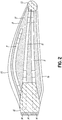
- one half 8 of the outer shell of a wind turbine blade is formed with three elongate reinforcing structures 9, 10, 11, to be described in greater detail below.
- Two of the reinforcing structures 9, 10 extend substantially along the full length of the turbine blade from the root section 12 to the blade tip 13.
- the root section 12 of the blade is formed with threaded metallic inserts 14 for receiving bolts by which the blade is attached to the central hub of the wind turbine, as described above with reference to Figure 1 .
- the third reinforcing structure 11 extends only part-way along the blade from the root section 12 and is also laterally displaced from the other two reinforcing structures 9, 10 towards the trailing edge 15 of the blade and away from the leading edge 16 of the blade.
- the two reinforcing structures 9, 10 form the spar caps of the wind turbine blade and the third reinforcing structure 11 acts as a stiffener for the trailing edge 15.
- the ends of the three reinforcing structures 9, 10, 11 within the root section 12 of the blade are encased in a glass-reinforced plastics (GRP) material for added strength and stability, as are the distal ends of the two reinforcing structures 9, 10 which extend to the blade tip 13.
- GRP glass-reinforced plastics
- the remaining portions of the outer shell are filled with structural foam 17, and the reinforcing structures 9, 10, 11 and the structural foam 17 are all formed within an outer skin and an inner skin to be described in greater detail below.
- the structural foam 17 is a lightweight core material, and it will be appreciated that other core materials can be used, such as wood, particularly balsa wood, and honeycomb.
- the complete turbine blade is formed from the upper half 8 of the outer shell shown in Figure 2 , together with a corresponding lower half and two internal webs.
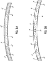
- FIG. 3(a) illustrates a cross-sectional view of a conventional arrangement in which each half-shell 8' comprises an inner skin 18' and an outer skin 19' between which only a single reinforcing structure 9' is provided.
- the regions between the inner skin 18' and the outer skin 19' to each side of the reinforcing structure 9' are filled with structural foam 17'.
- the reinforcing structure 9' is formed with a substantially rectangular cross-section, it follows that that substantial voids 20' are formed between the outer skin 19' and the central region of the reinforcing structure 9', and between the inner skin 18' and the end regions of the reinforcing structure 9'.
- resin is introduced into these voids 20', which is undesirable in a composite structure, since this increases both the weight and the cost of the blade, and could also give rise to structural problems.
- Figure 3(b) is a cross-sectional view of a preferred embodiment of the present invention in which each half-shell 8 is provided with at least two reinforcing structures 9, 10 provided between the inner skin 18 and the outer skin 19.
- the volume of the resulting voids 20 which are formed between the outer skin 19 and the central region of the reinforcing structure 9, and between the inner skin 18 and the end regions of the reinforcing structure 9 is substantially less than that of the voids 20' which occur when only a single reinforcing structure 9' is provided.
- the amount of resin required to fill the voids 20 during the moulding process is substantially less.
- the overall widths of the reinforcing structures are located more closely to the outer skin 19 of the wind turbine blade. This is advantageous for structural reasons, since it provides a higher second moment of inertia such that the wind turbine blade has a greater resistance to bending.
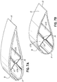
- Figures 4(a) to 4(e) are cross-sectional representations of the complete turbine blade at different positions along the length of the blade.
- Figure 4(a) represents the blade near the blade tip 13, from which it can be seen that only the first two reinforcing structures 9, 10 are present at this position along length of the upper half of the outer shell shown in Figure 2 .
- the lower half 21 of the outer shell is also provided with three reinforcing structures 22, 23, 24, again only two of which 22, 23 are present at this position.
- a resilient elongate web 25 made from a layer of balsa wood or lightweight foam sandwiched between two outer layers of GRP and having a generally X-shaped longitudinal cross section is provided within the outer shall and serves to transfer the shear forces which act on the turbine blade in use.
- One of the two diagonal arms of the X-shape extends between a first pair of the reinforcing structures 9, 23, and the other diagonal arm extends between a second pair of the reinforcing structures 10, 22.
- Figure 4(c) represents the central section of the turbine blade, from which it can be seen that a further resilient elongate web 26 having a generally Z-shaped longitudinal cross section is provided which extends between the two reinforcing structures 11, 24 at the trailing edge 15 of the blade.
- the two outer limbs of the Z-shape act as flanges for connecting the Z-shaped web 26 to the two associated reinforcing structures 11, 24.
- the reinforcing structure 22 is sandwiched between the inner skin 18 and the outer skin 19, and the remaining parts of the outer shell are formed from a layer of structural foam 17, also sandwiched between the inner and outer skins 18, 19.
- the skins are made from GRP.
- the reinforcing structure 22 is in the form of a stack 27 of layers of pultruded fibrous composite strips supported within a U-shaped channel 28, which in turn is supported on an elongate wedge 29 such that the base of the channel 28 is at an acute angle to the outer skin 19 of the shell.
- the channel 28 includes material which acts as a lightning conductor in use.
- the U-shaped channel 28 and the wedge 29 may be omitted.
- the end of the arm of the X-shaped web 25 is provided with a flange 30 for directing the shear force applied across the full width of the reinforcing structure 22 to the X-shaped web 25.
- Figure 4(e) illustrates a cross-sectional view of the blade between the central section represented in Figure 4(c) and the root section 12, and it can be seen that the reinforcing structures 9, 10, 11, 22, 23, 24 within each half-shell are closer together than at the central section of the blade, reflecting the curvature of the reinforcing structures.
- the reinforcing structures 9, 10, 22 and 23 are spar caps which, together with the shear webs 25, form the main structural spar of the wind turbine blade.
- the reinforcing structures 11 and 24 at the trailing edge stiffen the wind turbine blade in the region of the trailing edge to provide stability against buckling and, together with the web 26, form a trailing edge spar.
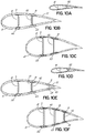
- Each of the stacks 27 of the reinforcing structures 9, 10, 11, 22, 23, 24 is tapered longitudinally at both ends. This is achieved by a reduction in the number of layers of pultruded fibrous strips from five at the central section to only a single layer at each end. This feature is indicated in the drawings, wherein, in Figures 4(a) and 4(e) , the respective stacks 27 of the reinforcing structures 9, 10, 22, 23, 24 have only a single layer, whereas the stacks 27 within the central section illustrated in Figure 4(c) have five layers.
- This feature enables the reinforcing structures 9, 10, 11, 22, 23, 24 to adopt a profile consistent with the thickness profile of the outer shell of the blade.
- each layer 31 is chamfered at both ends so as to remove the square-cut ends which are formed during the cutting of the pultruded strips which form the layers 31.
- the stack 27 is covered with a top layer 33 formed from an additional pultruded fibrous composite strip having a lesser thickness than that of the underlying layers 31. Since the top layer 33 is thinner than the other layers 31, it is also more flexible and therefore able to bend around the angled chamfered ends of the stack 27 within the tapered end regions to form a relatively smooth upper surface.
- Each layer 31 within the stack has a thickness of approximately 4 mm, and the thickness of the top layer is approximately 1 mm.
- Figures 6(a) to 6(c) are longitudinal cross-sectional views showing three different arrangements of pultruded fibrous composite strips, or pultrusion strips 34 within the five layers 31.
- each layer 31 has only a single pultrusion strip 34 within each layer.
- each layer 31 is formed from a parallel arrangement of three pultrusion strips 34 of equal width laid together side by side.
- each layer 31 has either three or four pultrusion strips 34 in a parallel side-by-side arrangement, but containing pultrusion strips 34 of two different widths.
- each of the pultrusion strips 34 within the above three arrangements extends the full length of the respective layer 31, although it may be beneficial in some embodiments for at least some of the layers 31 to include shorter strips 34 which are arranged end to end.
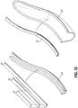
- Figures 7(a) and 7(b) illustrate in greater detail the central section and root section 12 respectively of the wind turbine blade showing the X-shaped resilient web 25.
- the reinforcing structures are not shown in the drawings, for the sake of clarity.
- the web is formed in two generally V-shaped halves 25a, 25b, and the lower ends of each half 25a, 25b as viewed in the drawings is attached to the lower half of the outer shell by means of a layer of adhesive (not shown), and the two halves 25a, 25b of the web 25 are joined together by bolts 36.
- Figure 8 is a longitudinal cross-sectional view illustrating in greater detail the region of the outer shell which includes a reinforcing structure 22 within a lower half-mould 37.
- the outer skin 19 in the form of a dry fibre cloth, or a plurality of superposed and/or overlapping dry fibre cloths, is first placed on the surface of the half-mould 37, and elongate wedges 29 are then positioned on the outer skin 19 along the curvilinear regions where the reinforcing structures 9, 10, 11, 22, 23, 24 are to be positioned.
- the inner skin described further below, is also formed by a dry fibre cloth, or a plurality of superposed and/or overlapping dry fibre cloths.
- the dry cloths are, once positioned in the half-moulds with other components as described below, impregnated with resin supplied into the half-moulds, e.g. in an infusion process, such as the one described below.
- the inner and outer skin could be provided from prepreg (pre-impregnated fibre) cloths, where the resin is supplied into the half-moulds together with the fibre material of the cloths.
- the reinforcing structures are positioned along respective upper surfaces of the wedges 29. This can be achieved by firstly positioning the U-shaped channel 28 of each reinforcing structure along the upper surface of the wedge 29 and then introducing the stack 27 of pultruded layers of fibrous composite strips into the channel 28, or alternatively forming the entire reinforcing structure outside the half-mould 37 and then placing it along the upper surface of the wedge 29. In either case, the reinforcing structure can be lowered into position on the wedge 29 or slid into position along the surface of the wedge 29.
- the orientation of the upper surfaces of the wedges 29 is varied along their length in dependence on the curvature of the linear regions so as to retain the reinforcing structures in the desired positions.
- a layer of structural foam 17 is then introduced into the half-mould 37 to fill the regions between the reinforcing structures 9, 10, 11, 22, 23, 24.
- the inner skin 18, in the form of a dry fibre cloth, or a plurality of superposed and/or overlapping dry fibre cloths, is then placed on the upper surfaces of the reinforcing structures and the structural foam 17 and the components covered with an airtight bag to form an evacuation chamber which is subsequently evacuated and resin introduced, as described in greater detail below.
- the components within the lower half-mould 37 are then heated and the resin thereby cured so as to form the lower outer half-shell of the blade.
- the inner skin 18 and the outer skin 19 are formed in this embodiment from a layer of biax glass cloth, although multiple layers may alternatively be used. As mentioned above, it would also be possible to omit the U-shaped channel 28 and the elongate wedges 29 so that the stack 27 is formed and located directly on the outer skin 19. It would also be possible to position the structural foam 17 on the outer skin 19 and then subsequently to introduce the stack 28 into the mould 37.
- An upper half-mould with an outer shell is then positioned above the lower half-mould 37 mould so as to form the complete outer shell of the blade.
- Figure 9(a) illustrates the overall structure of the components of the lower half of the outer shell when in the lower mould-half 37.
- an air-tight sealing layer i.e. a vacuum bag
- a vacuum pump 39 With the pump 39 still energised, a supply of liquid resin 40 is connected to the chamber so as to infuse both the components and the interstitial spaces therebetween. A corresponding infusion process is applied to the components of the upper half of the outer shell.
- the pump 39 continues to operate during a subsequent moulding operation in which the mould is heated so as to cure the resin, although during the curing process the extent of de-pressurisation may be lowered.
- the X-shaped web 25 and the Z-shaped web 26 are then attached by means of adhesive to the inner skin 18 immediately above the reinforcing structures 22, 23, 24 in the lower half-mould 37, and the upper free ends of the webs 25, 26 are coated with respective layers of adhesive.
- the upper half-mould is then pivoted into position above the lower half-mould 37, and the two half-moulds connected together. This causes the reinforcing structures 9, 10, 11 within the upper half-mould to adhere to the upper free ends of the webs 25, 26.
- the resilient nature of the webs 25, 26 give rise to a biasing force of the webs 25, 26 against the upper reinforcing structures 9, 10, 11 so as to ensure good adhesion.
- the leading edge of the blade is formed along leading edges of the respective half-moulds, and trailing edge of the blade is formed along trailing edges of the respective half-moulds.
- the mould is then opened, and the finished turbine blade lifted from the mould.
- FIGS 10(a) to 10(f) are cross-sectional illustrations of alternative embodiments of wind turbine blades in which each of the webs 41, 42, 43 is of I-shaped cross section, which, in combination with the associated reinforcing structures, results in an I-beam construction. Since each of the webs is provided with a flange 30 at each end, these could alternatively be considered as C-section webs, where the arms of the C-shape constitute the flanges 30.
- Figures 10(a) to 10(c) there are only four reinforcing structures 9, 10, 22, 23.
- Figure 10(a) represents a cross sectional view near the blade tip
- Figure 10(b) a sectional view mid-way along the blade
- Figure 10(c) a sectional view near the root end, where it can be seen that the thickness of the reinforcing structure 9, 10, 22, 23 is tapered.
- the reinforcing structures within each half-shell are closer together near the tip of the blade.
- Figures 10(d) to 10(f) there are six reinforcing structures 9, 10, 11, 22, 23, 24, and a respective I-shaped web 41, 42, 43 linking each pair of opposed structures 9, 19; 10, 23; and 11, 24.
- Figure 10(d) represents a cross sectional view near the blade tip
- Figure 10(e) a sectional view mid-way along the blade
- Figure 10(f) a sectional view near the root end, where again it can be seen that the thickness of the reinforcing structure 9, 10, 22, 23 is tapered.
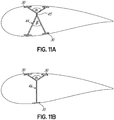
- Figures 11(a) and 11(b) illustrate two further forms of web.
- the web 44 has an X-shaped cross section in which the two diagonals are bent at the intersection 45, so that the upper limbs diverge at an angle ⁇ which is greater than the angle ⁇ between the lower two limbs.
- An advantage of this arrangement is that the upper wide angle gives rise to additional flexibility when the two half-moulds are closed, while the lower limbs serve merely to bridge the gap between the two shells.
- the lower two limbs have been combined into a single limb, resulting in a web 46 of Y-shaped cross section. Such a web can replace the X-shaped and/or Z-shaped webs described above.
- the method described above can be summarised as comprising a step 47 of providing the support surface within the lower half-mould 37, a step 48 of introducing reinforcing structures 9 into the lower half-mould 37 and a step 49 of sliding the reinforcing structures 9 along the surface of the wedge 29 into the respective desired positions.
- Figure 13 illustrates an alternative method, in which the pultruded strips 34 are placed in a separate mould, provided as a U-shaped channel 28, outside of the main half-mould 50, together with a matrix (resin or adhesive) which is pre-cured so that the stack 27 is formed in the separate mould 28.
- the pre-cured cured stack 27 is then placed in the main half-mould 50 for an infusion resin process together with the other structural elements.
- this method can be summarised as comprising the following steps: (a) forming a stack of fibrous layers 51; (b) pre-curing the stack of fibrous layers in a first mould 52; (c) introducing the pre-cured stack into a second mould 53; and (d) integrating the stack and the other structural elements together in the second mould 54.
- the stack can be partially cured in the first mould and then fully cured in the second mould.
- the stack can be fully cured in the first mould and integrated as such with the other structural elements in the second mould wherein some of other structural elements are cured.
- FIGS 15(a) to 15(c) illustrate schematically a further preferred embodiment, which may be combined with any of the embodiments described above.
- the elements are not drawn to scale.
- inner and outer pre-cured meshes 55, 56 formed from glass weave and pre-cured resin, and these are positioned between the respective inner and outer skins 18, 19 and the underlying reinforcing structures 9, 10.
- the meshes 55, 56 extend over the regions where the underlying reinforcing structures 9, 10 abut the core material 17.
- the two reinforcing structures 9, 10 are closely separated, as illustrated in the cross-sectional view of Figure 15(a) taken along the line A - A' of Figure 15(c) .
- each of the inner and outer meshes 55, 56 extends across both of the underlying reinforcing structures 9, 10, so as to cover all of the four transition regions between the reinforcing structure 9, 10 and the core material 17.
- the two reinforcing structures 9, 10 are further apart, as illustrated in the cross-sectional view of Figure 15(b) taken along the line B - B' of Figure 15(c) .
- each of the inner and outer meshes 55, 56 extends across only a respective one of the underlying reinforcing structures 9, 10, so as to cover only the two transition regions between the respective reinforcing structure, e.g. 9 and the adjacent core material 17.
- the function of the inner and outer meshes 55, 56 is to prevent the inner and outer skins 17, 18 from wrinkling due to: (a) gaps between the underlying reinforcing structures 9, 10 and the adjacent core material 17; and (b) any slight differences between the thickness of the underlying reinforcing structures 9, 10 and the thickness of the core material 17.
- Figure 15(c) is a plan view of this arrangement, from which it can be seen that the meshes 55, 56 form an approximate V-shape.
- the outlines of the reinforcing structures 9, 10 sandwiched between the inner and outer meshes 55, 56 are illustrated in the drawing by the dashed line.
- the side edges of the inner and outer meshes 55, 56 extend about 20 mm over the underlying core material. It would also be possible to provide a single pre-cured mesh 55 located under the reinforcing structures 9, 10 and the core material 17.
- fibres which are pre-impregnated with resin may be used for the inner and outer skins, in which case it would not be necessary to infuse resin into the shell construction.
- pre-preg fibres may be used for the inner and outer skins, in which case it would not be necessary to infuse resin into the shell construction.
- adhesive film layers can be provided between the individual layers in the stack so that they adhere together when the structure is cured.
Claims (14)
- Windturbinenblatt, von im Allgemeinen hohler Konstruktion und gebildet von einer ersten und einer zweiten gegenüberliegenden Halbschale;
wobei jede Halbschale (8) eine Innenhaut (18) und eine Außenhaut (19) und eine erste und eine zweite längliche Verstärkungsstruktur (9, 10, 22, 23), die sich zwischen der Innen- und der Außenhaut befinden, umfasst;
wobei sich jede Verstärkungsstruktur (9, 10, 22, 23) entlang der Längsrichtung des Blatts erstreckt und einen Stapel (27) von Schichten (31) umfasst;
wobei jeder Stapel (27) eine Dicke aufweist, die sich in einer Richtung im Wesentlichen senkrecht zu einer Oberfläche des Blatts erstreckt;
wobei sich jede Schicht (31) über eine Breite des jeweiligen Stapels (27) erstreckt, wobei die Breite senkrecht zu der Längsrichtung des Blatts und senkrecht zu der Dicke des Stapels ist und wobei jede Schicht zumindest einen vorausgehärteten gezogenen faserigen Verbundstreifen (34) umfasst;
wobei jede Halbschale (8) weiter Kernmaterial (17) umfasst, das zwischen der Innen- (18) und der Außenhaut (19) angeordnet ist und sich erstreckt: (a) zwischen der ersten (9, 22) und der zweiten (10, 23) länglichen Verstärkungsstruktur; (b) von der ersten länglichen Verstärkungsstruktur in Richtung einer Vorderkante (16) des Blatts; und (c) von der zweiten länglichen Verstärkungsstruktur in Richtung einer Hinterkante (15) des Blatts;
wobei das Windturbinenblatt weiter einen ersten länglichen Steg (41), der sich zwischen der ersten Verstärkungsstruktur (9) in der ersten Halbschale und der ersten Verstärkungsstruktur (22) in der zweiten Halbschale erstreckt, und einen zweiten länglichen Steg (42), der sich zwischen der zweiten Verstärkungsstruktur (10) in der ersten Halbschale und der zweiten Verstärkungsstruktur (23) in der zweiten Halbschale erstreckt, umfasst. - Windturbinenblatt nach Anspruch 1, wobei die länglichen Verstärkungsstrukturen (9, 10, 22, 23) und das Kernmaterial (17) Anlagekanten definieren, die im Wesentlichen senkrecht zu der Oberfläche des Windturbinenblatts sind.
- Windturbinenblatt nach einem vorstehenden Anspruch, weiter umfassend, in jeder Halbschale, ein vorausgehärtetes Gitter (56), das sich zwischen der Außenhaut (19) und zumindest einer von den länglichen Verstärkungsstrukturen (9, 10, 22, 23) befindet.
- Windturbinenblatt nach einem vorstehenden Anspruch, weiter umfassend, in jeder Halbschale, ein vorausgehärtetes Gitter (55), das sich zwischen der Innenhaut (18) und zumindest einer von den länglichen Verstärkungsstrukturen (9, 10, 22, 23) befindet.
- Windturbinenblatt nach einem vorstehenden Anspruch, weiter umfassend, in zumindest einer der Halbschalen, ein vorausgehärtetes Gitter (56), das sich zwischen der Außenhaut (19) und einem Anlagebereich von einer der länglichen Verstärkungsstrukturen (9, 10, 22, 23) und dem Kernmaterial (17) befindet.
- Windturbinenblatt nach einem vorstehenden Anspruch, weiter umfassend, in zumindest einer der Halbschalen, ein vorausgehärtetes Gitter (55), das sich zwischen der Innenhaut (18) und einem Anlagebereich von einer der länglichen Verstärkungsstrukturen (9, 10, 22, 23) und dem Kernmaterial (17) befindet.
- Windturbinenblatt nach einem vorstehenden Anspruch, wobei die Schichten (31) verschiedenen Längen aufweisen, sodass die Dicke des Stapels (27) in Richtung von zumindest einem Ende verjüngt ist.
- Windturbinenblatt nach Anspruch 7, wobei zumindest eines der zwei Enden jeder Schicht (31) abgeschrägt ist.
- Windturbinenblatt nach einem vorstehenden Anspruch, wobei jede Schicht (31) einen einzelnen gezogenen faserigen Verbundstreifen (34) umfasst, der sich über die gesamte Breite der Schicht erstreckt.
- Windturbinenblatt nach einem der Ansprüche 1 bis 8, wobei jede Schicht (31) eine Mehrzahl von gezogenen faserigen Verbundstreifen (34) umfasst.
- Windturbinenblatt nach einem vorstehenden Anspruch, wobei der Stapel (27) weiter eine Deckschicht (33) umfasst, die sich über die gesamte Länge des Stapels erstreckt, wobei die Dicke der Deckschicht im Wesentlichen geringer als die Dicke der anderen Schichten in dem Stapel ist.
- Windturbinenblatt nach einem vorstehenden Anspruch, wobei die gezogenen faserigen Verbundstreifen (34) aus Fasern gebildet sind, die ausgewählt sind, aus: Kohlenstofffasern; Glasfasern; Aramidfasern; und Naturfasern, einschließlich Holzfasern und organischen Fasern.
- Windturbinenblatt nach einem vorstehenden Anspruch, wobei sich die Innen- und die Außenhaut (18, 19) im Wesentlichen ununterbrochen über das Kernmaterial (17) und die Verstärkungsstrukturen (9, 10, 22, 23) erstreckt.
- Verfahren zum Herstellen eines Windturbinenblatts, von im Allgemeinen hohler Konstruktion und eine erste und eine zweite Halbschale umfassend;
Anordnen, in jeder von einer ersten und einer zweiten länglichen Halbform, eines oder mehrerer Fasergewebe für jeweilige Außenhäute (19);
Lokalisieren, in jeder von der ersten und der zweiten länglichen Halbform, einer ersten und einer zweiten länglichen Verstärkungsstruktur (9, 10, 22, 23) auf den Fasergeweben für die Außenhäute, um sich entlang der Längsrichtung der jeweiligen Halbformen zu erstrecken;
wobei jede Verstärkungsstruktur (9, 10, 22, 23) einen Stapel (27) von Schichten (31) umfasst, wobei jeder Stapel eine Dicke aufweist, die sich in einer Richtung im Wesentlichen senkrecht zu einer Oberfläche der jeweiligen Halbform erstreckt;
wobei sich jede Schicht (31) über eine Breite des jeweiligen Stapels (27) erstreckt, wobei die Breite senkrecht zu der Längsrichtung der jeweiligen Halbform und senkrecht zu der Dicke des Stapels ist und wobei jede Schicht zumindest einen vorausgehärteten gezogenen faserigen Verbundstreifen (34) umfasst;
Anordnen in jeder der jeweiligen Halbformen Kernmaterial (17) auf den Fasergeweben für die Außenhaut (19), um sich zu erstrecken: (a) zwischen der ersten (9, 22) und der zweiten (10, 23) länglichen Verstärkungsstruktur; (b) von der ersten länglichen Verstärkungsstruktur in Richtung einer Vorderkante der jeweiligen Halbform; und (c) von der zweiten länglichen Verstärkungsstruktur in Richtung einer Hinterkante der jeweiligen Halbform;
Anordnen, in jeder von einer ersten und einer zweiten länglichen Halbform, auf oberen Oberflächen der ersten und der zweiten länglichen Verstärkungsstruktur und des Kernmaterials, ein oder mehrere Fasergewebe für jeweilige Innenhäute (18);
Zuführen von Harz (40) in die erste und die zweite Halbform; anschließendes Aushärten des Harzes (40), um die erste und die zweite Halbschale zu bilden;
anschließendes Anordnen eines ersten länglichen Stegs (41) und eines zweiten länglichen Stegs (42) in einer der Halbformen; und
Schwenken der ersten Halbform in eine Position über der zweiten Halbform, damit sich der erste längliche Steg (41) zwischen der ersten Verstärkungsstruktur (9) in der ersten Halbschale und der ersten Verstärkungsstruktur (22) in der zweiten Halbschale erstreckt, und damit sich der zweite längliche Steg (42) zwischen der zweiten Verstärkungsstruktur (10) in der ersten Halbschale und der zweiten Verstärkungsstruktur (23) in der zweiten Halbschale erstreckt.
Priority Applications (3)
| Application Number | Priority Date | Filing Date | Title |
|---|---|---|---|
| EP21159223.3A EP3859143A1 (de) | 2011-12-16 | 2012-12-11 | Windturbinenrotorblätter |
| DK19156353.5T DK3505751T3 (da) | 2011-12-16 | 2012-12-11 | Vindmøllevinger |
| EP19156353.5A EP3505751B1 (de) | 2011-12-16 | 2012-12-11 | Windturbinenrotorblätter |
Applications Claiming Priority (3)
| Application Number | Priority Date | Filing Date | Title |
|---|---|---|---|
| GB1121649.6A GB2497578B (en) | 2011-12-16 | 2011-12-16 | Wind turbine blades |
| US201261588247P | 2012-01-19 | 2012-01-19 | |
| PCT/DK2012/050458 WO2013087078A1 (en) | 2011-12-16 | 2012-12-11 | Wind turbine blades |
Related Child Applications (2)
| Application Number | Title | Priority Date | Filing Date |
|---|---|---|---|
| EP21159223.3A Division EP3859143A1 (de) | 2011-12-16 | 2012-12-11 | Windturbinenrotorblätter |
| EP19156353.5A Division EP3505751B1 (de) | 2011-12-16 | 2012-12-11 | Windturbinenrotorblätter |
Publications (2)
| Publication Number | Publication Date |
|---|---|
| EP2791500A1 EP2791500A1 (de) | 2014-10-22 |
| EP2791500B1 true EP2791500B1 (de) | 2019-03-06 |
Family
ID=45560559
Family Applications (3)
| Application Number | Title | Priority Date | Filing Date |
|---|---|---|---|
| EP19156353.5A Active EP3505751B1 (de) | 2011-12-16 | 2012-12-11 | Windturbinenrotorblätter |
| EP21159223.3A Pending EP3859143A1 (de) | 2011-12-16 | 2012-12-11 | Windturbinenrotorblätter |
| EP12805931.8A Revoked EP2791500B1 (de) | 2011-12-16 | 2012-12-11 | Windturbinenrotorblatt und produktionsverfahren |
Family Applications Before (2)
| Application Number | Title | Priority Date | Filing Date |
|---|---|---|---|
| EP19156353.5A Active EP3505751B1 (de) | 2011-12-16 | 2012-12-11 | Windturbinenrotorblätter |
| EP21159223.3A Pending EP3859143A1 (de) | 2011-12-16 | 2012-12-11 | Windturbinenrotorblätter |
Country Status (11)
| Country | Link |
|---|---|
| US (3) | US10487797B2 (de) |
| EP (3) | EP3505751B1 (de) |
| JP (1) | JP6105619B2 (de) |
| KR (1) | KR101642066B1 (de) |
| CN (1) | CN104114856B (de) |
| BR (1) | BR112014014708B1 (de) |
| CA (1) | CA2858397C (de) |
| DK (2) | DK2791500T3 (de) |
| ES (2) | ES2869238T3 (de) |
| GB (1) | GB2497578B (de) |
| WO (1) | WO2013087078A1 (de) |
Cited By (7)
| Publication number | Priority date | Publication date | Assignee | Title |
|---|---|---|---|---|
| EP3792049A1 (de) | 2019-09-13 | 2021-03-17 | Siemens Gamesa Renewable Energy Innovation & Technology, S.L. | Windturbinenschaufel |
| EP3792481A1 (de) | 2019-09-13 | 2021-03-17 | Siemens Gamesa Renewable Energy Innovation & Technology, S.L. | Windturbinenschaufel |
| EP3792480A1 (de) | 2019-09-13 | 2021-03-17 | Siemens Gamesa Renewable Energy Innovation & Technology, S.L. | Windturbinenschaufel |
| WO2021048403A1 (en) | 2019-09-13 | 2021-03-18 | Siemens Gamesa Renewable Energy Innovation & Technology S.L. | Wind turbine blade |
| EP3825544A1 (de) | 2019-11-25 | 2021-05-26 | Siemens Gamesa Renewable Energy Innovation & Technology, S.L. | Windturbinenschaufel |
| US11371482B2 (en) | 2011-12-16 | 2022-06-28 | Vestas Wind Systems A/S | Wind turbine blades |
| EP3884157B1 (de) * | 2018-11-20 | 2022-09-28 | Vestas Wind Systems A/S | Äquipotenzialbonden einer windturbinenrotorschaufel |
Families Citing this family (109)
| Publication number | Priority date | Publication date | Assignee | Title |
|---|---|---|---|---|
| US10875287B2 (en) | 2012-09-18 | 2020-12-29 | Vestas Wind Systems A/S | Wind turbine blades |
| DE102012219224B3 (de) * | 2012-10-22 | 2014-03-27 | Repower Systems Se | System und Verfahren zum Herstellen eines Rotorblattgurtes |
| US8973871B2 (en) * | 2013-01-26 | 2015-03-10 | The Boeing Company | Box structures for carrying loads and methods of making the same |
| US20140322025A1 (en) * | 2013-04-25 | 2014-10-30 | Wetzel Engineering, Inc. | Structural Member with X-Web |
| GB2521809A (en) * | 2013-10-17 | 2015-07-08 | Vestas Wind Sys As | Improvements relating to lightning protection systems for wind turbine blades |
| GB2519566A (en) * | 2013-10-25 | 2015-04-29 | Vestas Wind Sys As | Wind turbine blades |
| GB2520007A (en) * | 2013-11-05 | 2015-05-13 | Vestas Wind Sys As | Improvements relating to wind turbine rotor blades |
| GB2520079A (en) * | 2013-11-11 | 2015-05-13 | Vestas Wind Sys As | Wind turbine blades |
| GB2520082A (en) * | 2013-11-11 | 2015-05-13 | Vestas Wind Sys As | Wind turbine blades |
| GB201320166D0 (en) | 2013-11-15 | 2014-01-01 | Vestas Wind Sys As | Wind turbine components |
| DK3077661T3 (da) * | 2013-12-04 | 2022-10-17 | Vestas Wind Sys As | Forbøjet vindmøllevinge |
| EP3086924A1 (de) | 2013-12-23 | 2016-11-02 | Vestas Wind Systems A/S | Windturbinenschaufeln |
| US20150252780A1 (en) * | 2014-03-07 | 2015-09-10 | Siemens Aktiengesellschaft | Wind turbine blade spar web having enhanced buckling strength |
| EP2918399B1 (de) * | 2014-03-10 | 2021-04-28 | Siemens Gamesa Renewable Energy A/S | Verfahren zur Herstellung eines Windturbinenrotorblatts |
| ES2610980T3 (es) * | 2014-04-10 | 2017-05-04 | Nordex Energy Gmbh | Módulo de correa para una pala de rotor de la instalación de energía eólica |
| US10066600B2 (en) | 2014-05-01 | 2018-09-04 | Tpi Composites, Inc. | Wind turbine rotor blade and method of construction |
| GB2528852A (en) * | 2014-07-31 | 2016-02-10 | Vestas Wind Sys As | Composite component having a safety edge |
| GB2528850A (en) | 2014-07-31 | 2016-02-10 | Vestas Wind Sys As | Improvements relating to reinforcing structures for wind turbine blades |
| US20160040651A1 (en) * | 2014-08-07 | 2016-02-11 | General Electric Company | Methods of manufacturing rotor blades of a wind turbine |
| GB2529186A (en) * | 2014-08-12 | 2016-02-17 | Vestas Wind Sys As | Improvements relating to wind turbine blade manufacture |
| US9822761B2 (en) | 2014-08-13 | 2017-11-21 | General Electric Company | Structural components and methods of manufacturing |
| CN105508142B (zh) * | 2014-10-15 | 2018-06-05 | 株洲时代新材料科技股份有限公司 | 一种多梁结构大尺寸风电叶片及其的制作方法 |
| US20160146185A1 (en) * | 2014-11-25 | 2016-05-26 | General Electric Company | Methods for manufacturing a spar cap for a wind turbine rotor blade |
| US20160160837A1 (en) * | 2014-12-04 | 2016-06-09 | General Electric Company | Pultruded rotor blade components having interlocking edges |
| DE102014018498A1 (de) * | 2014-12-16 | 2016-06-16 | Senvion Gmbh | Anordnung pultrudierter Stäbe |
| WO2016189051A1 (en) * | 2015-05-28 | 2016-12-01 | Lm Wp Patent Holding A/S | Wind turbine blade with a trailing edge spacing section |
| US20160377052A1 (en) * | 2015-06-29 | 2016-12-29 | General Electric Company | Blade root section for a modular rotor blade and method of manufacturing same |
| US9897065B2 (en) | 2015-06-29 | 2018-02-20 | General Electric Company | Modular wind turbine rotor blades and methods of assembling same |
| US10337490B2 (en) | 2015-06-29 | 2019-07-02 | General Electric Company | Structural component for a modular rotor blade |
| US10072632B2 (en) * | 2015-06-30 | 2018-09-11 | General Electric Company | Spar cap for a wind turbine rotor blade formed from pre-cured laminate plates of varying thicknesses |
| US10077758B2 (en) * | 2015-06-30 | 2018-09-18 | General Electric Company | Corrugated pre-cured laminate plates for use within wind turbine rotor blades |
| US20180245566A1 (en) * | 2015-08-24 | 2018-08-30 | Hitachi, Ltd. | Wind Power Generation Device |
| US10533534B2 (en) * | 2015-09-09 | 2020-01-14 | General Electric Company | Composite layers for bonding components of a wind turbine rotor blade |
| EP3380313B1 (de) * | 2015-11-26 | 2019-08-07 | Vestas Wind Systems A/S | Verbesserung im zusammenhang mit der herstellung von windturbinenschaufeln |
| US11125206B2 (en) | 2015-11-30 | 2021-09-21 | Vestas Wind Systems A/S | Method of manufacturing a wind turbine blade and wind turbine blade |
| CA3011493C (en) | 2016-01-29 | 2020-07-21 | Wobben Properties Gmbh | Spar cap and production method |
| US10399285B2 (en) | 2016-02-08 | 2019-09-03 | Bell Helicopter Textron Inc. | Composite wing structure and methods of manufacture |
| MA45494A (fr) * | 2016-06-22 | 2019-05-01 | Lm Wind Power Int Tech Ii Aps | Pale d'éolienne à joints de colle améliorés et procédé associé |
| DE102016007675A1 (de) * | 2016-06-24 | 2017-12-28 | Senvion Gmbh | Hinterkantengurt mit Rechteckquerschnitt |
| US10648456B2 (en) * | 2016-10-21 | 2020-05-12 | General Electric Company | Organic conductive elements for deicing and lightning protection of a wind turbine rotor blade |
| DE102016013064A1 (de) * | 2016-11-03 | 2018-05-03 | Senvion Gmbh | Rotorblatt mit gekrümmten Pultrudaten |
| WO2018091054A1 (en) | 2016-11-17 | 2018-05-24 | Vestas Wind Systems A/S | A reinforcing structure for a wind turbine blade |
| ES2826554T3 (es) * | 2016-12-05 | 2021-05-18 | Nordex Energy Se & Co Kg | Módulo de correa para una pala de rotor de una instalación de energía eólica |
| EP3330528B1 (de) * | 2016-12-05 | 2020-07-22 | Nordex Energy GmbH | Gurtbaugruppe für ein windenergieanlagenrotorblatt |
| CN106671316B (zh) * | 2016-12-27 | 2019-02-19 | 锡林浩特晨飞风电设备有限公司 | 一种风力发电机叶片的粘接角模具制作方法 |
| CN116968339A (zh) * | 2016-12-31 | 2023-10-31 | 郑州泽正技术服务有限公司 | 一种纤维织物复合材料结构件及其制备方法 |
| CN108262983A (zh) * | 2016-12-31 | 2018-07-10 | 郑州吉田专利运营有限公司 | 碳纤维织物复合材料整车骨架及其制备方法 |
| US10527023B2 (en) | 2017-02-09 | 2020-01-07 | General Electric Company | Methods for manufacturing spar caps for wind turbine rotor blades |
| US10738759B2 (en) | 2017-02-09 | 2020-08-11 | General Electric Company | Methods for manufacturing spar caps for wind turbine rotor blades |
| US10828843B2 (en) | 2017-03-16 | 2020-11-10 | General Electric Company | Shear webs for wind turbine rotor blades and methods for manufacturing same |
| DE102017108902A1 (de) | 2017-04-26 | 2018-10-31 | Wobben Properties Gmbh | Verfahren zur zeitgleichen Herstellung von zwei oder mehr Faserverbundbauteilen sowie Faserverbundbauteil |
| CN106945306A (zh) * | 2017-05-11 | 2017-07-14 | 常州市宏发纵横新材料科技股份有限公司 | 采用拉挤成型的板材制作风电叶片的工艺 |
| US10465653B2 (en) | 2017-06-21 | 2019-11-05 | General Electric Company | Wind turbine blade with hybrid spar cap and associated method for making |
| US10619622B2 (en) | 2017-06-21 | 2020-04-14 | General Electric Company | Wind turbine blade with hybrid spar cap and associated method for making |
| US10844724B2 (en) * | 2017-06-26 | 2020-11-24 | General Electric Company | Additively manufactured hollow body component with interior curved supports |
| EP3427931B1 (de) * | 2017-07-13 | 2020-03-11 | LM Wind Power International Technology II ApS | Windturbinenschaufel und verfahren zur herstellung der windturbinenschaufel |
| WO2019020152A1 (en) | 2017-07-27 | 2019-01-31 | Vestas Wind Systems A/S | FOOT OF SOUL FOR A SOUEL OF SHEAR |
| US11519382B2 (en) | 2017-10-02 | 2022-12-06 | Vestas Wind Systems A/S | Relating to structural components for wind turbine blades |
| US10677216B2 (en) * | 2017-10-24 | 2020-06-09 | General Electric Company | Wind turbine rotor blade components formed using pultruded rods |
| CN108481628B (zh) * | 2018-02-08 | 2020-12-01 | 株洲时代新材料科技股份有限公司 | 一种风电叶片腹板、风电叶片及制备风电叶片腹板的模具 |
| US11738530B2 (en) * | 2018-03-22 | 2023-08-29 | General Electric Company | Methods for manufacturing wind turbine rotor blade components |
| DK3787887T3 (da) * | 2018-05-01 | 2024-01-08 | Lm Wind Power As | Fremgangsmåder til fremstilling af bjælkekappe til vindmøllerotorvinge |
| CN112313068B (zh) * | 2018-05-01 | 2023-05-09 | 通用电气公司 | 用于制造用于风力涡轮转子叶片的翼梁帽的方法 |
| EP3787872A4 (de) * | 2018-05-03 | 2021-11-24 | General Electric Company | Holmsteg für windturbinenrotorblätter und verfahren zur herstellung davon |
| CN112512784B (zh) * | 2018-06-11 | 2022-05-24 | 维斯塔斯风力系统有限公司 | 风力涡轮机叶片翼梁结构及其制造方法 |
| CN110657061B (zh) * | 2018-06-29 | 2023-11-17 | 中材科技风电叶片股份有限公司 | 风电叶片板材、风电叶片及其制造方法 |
| US10895244B2 (en) * | 2018-09-25 | 2021-01-19 | General Electric Company | Joint interface for wind turbine rotor blade components |
| CN109228375B (zh) * | 2018-11-01 | 2023-08-18 | 成都纵横大鹏无人机科技有限公司 | 一种蒙皮成型方法 |
| DK3884152T3 (da) | 2018-11-20 | 2022-10-03 | Vestas Wind Sys As | Ækvipotentialforbindelse af vindmøllerotorvinge |
| DE102018009332A1 (de) | 2018-11-28 | 2020-05-28 | Senvion Gmbh | Rotorblatt mit Gurten mit verformbaren Pultrudaten |
| ES2959648T3 (es) * | 2018-12-10 | 2024-02-27 | Vestas Wind Sys As | Alma de cizallamiento de pala de turbina eólica, método de fabricación y pala de turbina eólica |
| EP3899245B1 (de) * | 2018-12-19 | 2024-03-13 | LM Wind Power A/S | Windturbinenlaufschaufelschale mit variierenden fasertypen |
| US10815795B2 (en) * | 2018-12-20 | 2020-10-27 | General Electric Company | Pre-tension and retention structure for composite fan blade |
| PT3719312T (pt) * | 2019-04-03 | 2022-06-28 | Siemens Gamesa Renewable Energy As | Pá de turbina eólica e turbina eólica |
| PT3719296T (pt) | 2019-04-03 | 2022-06-27 | Siemens Gamesa Renewable Energy As | Coroa de longarina para uma pá de turbina eólica de uma turbina eólica, pá de turbina eólica, turbina eólica e método para fabricar uma coroa de longarina para uma pá de turbina eólica de uma turbina eólica |
| US11572162B2 (en) * | 2019-05-29 | 2023-02-07 | Lockheed Martin Corporation | Securing assembly for a rotor blade |
| DE102019125779B4 (de) * | 2019-09-25 | 2024-03-21 | Man Energy Solutions Se | Schaufel einer Strömungsmaschine |
| CN114786929A (zh) * | 2019-10-15 | 2022-07-22 | 通用电气公司 | 用于制造具有硬化的网格结构的壳的方法 |
| FR3102392B1 (fr) * | 2019-10-29 | 2021-10-08 | Safran | Préforme fibreuse tissée pour réaliser une aube de soufflante en matériau composite |
| CN110836164B (zh) * | 2019-11-22 | 2023-11-24 | 中材科技风电叶片股份有限公司 | 条状件、梁及其制作方法、叶片和风电机组 |
| EP4069968B1 (de) | 2019-12-04 | 2024-01-31 | Vestas Wind Systems A/S | Äquipotenzialbonden einer windturbinenrotorschaufel |
| GB2606483A (en) | 2019-12-12 | 2022-11-09 | Vestas Wind Sys As | Blade portion mounting structure |
| EP3838576A1 (de) * | 2019-12-19 | 2021-06-23 | Siemens Gamesa Renewable Energy A/S | Verfahren zur handhabung einer windturbinenschaufel |
| CN113048007B (zh) * | 2019-12-26 | 2022-10-04 | 江苏金风科技有限公司 | 叶片、风力发电机组以及降低叶片呼吸效应的方法 |
| KR102250536B1 (ko) * | 2020-01-20 | 2021-05-11 | 두산중공업 주식회사 | 풍력 발전기의 블레이드 및 풍력 발전기의 블레이드 제조 방법 |
| KR102250535B1 (ko) * | 2020-01-20 | 2021-05-11 | 두산중공업 주식회사 | 풍력 발전기의 블레이드 및 이를 포함하는 풍력 발전기 |
| GB202002431D0 (en) * | 2020-02-21 | 2020-04-08 | Lm Wind Power As | Lightning protection system for a main laminate |
| US20230016436A1 (en) * | 2020-04-15 | 2023-01-19 | Lm Wind Power A/S | Reinforcing structure for a wind turbine blade |
| EP3904670A1 (de) | 2020-04-27 | 2021-11-03 | Siemens Gamesa Renewable Energy A/S | Windturbinenschaufel |
| CN111605256A (zh) * | 2020-04-29 | 2020-09-01 | 中材科技风电叶片股份有限公司 | 复合结构体及制造方法、叶片 |
| WO2021223887A1 (en) * | 2020-05-08 | 2021-11-11 | Blade Dynamics Limited | Wind turbine blade |
| WO2021239209A1 (en) * | 2020-05-25 | 2021-12-02 | Lm Wind Power A/S | Method for manufacturing a wind turbine blade and wind turbine blade obtained thereby |
| CN114286891B (zh) * | 2020-07-28 | 2023-10-20 | 远景能源有限公司 | 用于风机叶片的主梁及其制造方法 |
| WO2022057988A1 (en) * | 2020-09-15 | 2022-03-24 | Vestas Wind Systems A/S | Wind turbine blade |
| US11623723B2 (en) * | 2020-09-16 | 2023-04-11 | Aerostar International, Llc | Propeller blade assembly |
| CN112392651B (zh) * | 2020-10-13 | 2024-01-09 | 华能昭觉风力发电有限公司 | 一种基于风力环境变化的叶片预防性增强方法 |
| GB202016561D0 (en) * | 2020-10-19 | 2020-12-02 | Blade Dynamics Ltd | Wind turbine blade with reinforcing structure |
| CN112848404B (zh) * | 2021-02-07 | 2023-03-17 | 江阴市科诚技术有限公司 | 一种风电叶片主梁用拉挤板材后处理生产线脱膜布方法 |
| CN117062980A (zh) | 2021-03-09 | 2023-11-14 | 维斯塔斯风力系统有限公司 | 具有等电位结合的风力涡轮机转子叶片翼梁帽 |
| CN113183493B (zh) * | 2021-04-13 | 2022-10-21 | 中国航空制造技术研究院 | 用于尾缘带泡沫结构的蜂窝夹层壁板成型工装及成型方法 |
| KR102433672B1 (ko) * | 2021-05-04 | 2022-08-18 | 두산에너빌리티 주식회사 | 풍력 발전기 블레이드의 제작 방법 |
| KR102513583B1 (ko) | 2021-05-04 | 2023-03-22 | 두산에너빌리티 주식회사 | 풍력 발전기의 블레이드 및 이를 포함하는 풍력 발전기 |
| CN113454334A (zh) * | 2021-05-12 | 2021-09-28 | 远景能源有限公司 | 一种具有加强条的风机叶片及其制造方法 |
| WO2023274482A1 (en) * | 2021-06-30 | 2023-01-05 | Vestas Wind Systems A/S | A wind turbine blade |
| WO2023274481A1 (en) * | 2021-06-30 | 2023-01-05 | Vestas Wind Systems A/S | A blade for a wind turbine |
| WO2023117012A1 (en) * | 2021-12-21 | 2023-06-29 | Vestas Wind Systems A/S | Wind turbine blade |
| CN114571749B (zh) * | 2022-01-24 | 2023-04-25 | 国电联合动力技术有限公司 | 一种风电叶片的三维增强预制件及其制备方法 |
| CN114571714A (zh) * | 2022-02-07 | 2022-06-03 | 常州市新创智能科技有限公司 | 一种芯材组合式复合材料风电叶片及其制造方法 |
| WO2023222172A1 (en) | 2022-05-17 | 2023-11-23 | Vestas Wind Systems A/S | Equipotential bonding of wind turbine rotor blade |
Citations (19)
| Publication number | Priority date | Publication date | Assignee | Title |
|---|---|---|---|---|
| WO2003008800A1 (en) | 2001-07-19 | 2003-01-30 | Neg Micon A/S | Wind turbine blade |
| WO2006082479A1 (en) | 2005-02-03 | 2006-08-10 | Vestas Wind Systems A/S | Method of manufacturing a wind turbine blade shell member |
| EP1754589A1 (de) | 2005-08-17 | 2007-02-21 | General Electric Company | Verfahren zur Herstellung eines kontinuierlichen Laminats, insbesondere geeignet als Umschlag eines Holmes oder als anderer Teil eines Windturbinenflügels |
| US20080277053A1 (en) * | 2007-05-07 | 2008-11-13 | Siemens Aktiengesellschaft | Method for producing fibre reinforced laminated structures |
| WO2009059604A1 (en) | 2007-11-09 | 2009-05-14 | Vestas Wind Systems A/S | A structural mat for reinforcing a wind turbine blade structure, a wind turbine blade and a method for manufacturing a wind turbine blade |
| US20090169392A1 (en) * | 2006-03-24 | 2009-07-02 | Mitsubishi Heavy Industries Ltd. | Wind turbine blade with sufficiently high strength and light weight |
| US20090220747A1 (en) | 2008-03-03 | 2009-09-03 | Abe Karem | Wing and blade structure using pultruded composites |
| US20100143142A1 (en) | 2008-12-11 | 2010-06-10 | Afroz Akhtar | Sparcap system for wind turbine rotor blade and method of fabricating wind turbine rotor blade |
| US7841835B2 (en) | 2009-02-20 | 2010-11-30 | General Electric Company | Spar cap for wind turbine blades |
| DE102009024324A1 (de) | 2009-05-29 | 2010-12-02 | Nordex Energy Gmbh | Verfahren und Vorrichtung zur Montage eines Rotorblatts für eine Windenergieanlage |
| WO2011004540A1 (ja) | 2009-07-10 | 2011-01-13 | 三菱重工業株式会社 | 原子炉容器の管台作業システム |
| US20110135485A1 (en) | 2009-12-30 | 2011-06-09 | Jing Wang | Spar for a wind turbine rotor blade and method for fabricating the same |
| WO2011088372A1 (en) | 2010-01-14 | 2011-07-21 | Neptco, Inc. | Wind turbine rotor blade components and methods of making same |
| WO2011135306A1 (en) | 2010-04-30 | 2011-11-03 | Blade Dynamics Limited | A modular structural composite beam |
| US20120027609A1 (en) | 2011-05-17 | 2012-02-02 | Prasad Ogde | Wind turbine rotor blade with precured fiber rods and method for producing the same |
| US20120093656A1 (en) | 2009-07-09 | 2012-04-19 | Mitsubishi Heavy Industries, Ltd. | Wind turbine blade and method of manufacturing wind turbine blade |
| EP2497945A1 (de) | 2011-03-11 | 2012-09-12 | Epsilon Composite | Mechanische Verstärkung eines Verbundmaterialbauteils, insbesondere für Flügel einer Windkraftanlage großer Abmessungen |
| EP2567807A1 (de) | 2011-09-07 | 2013-03-13 | Nordex Energy GmbH | Verfahren zur Herstellung eines Windenergieanlagenrotorblattbauteils mit einem vorgefertigten Hauptgurt |
| GB2497578A (en) | 2011-12-16 | 2013-06-19 | Vestas Wind Sys As | Wind turbine blade structure |
Family Cites Families (14)
| Publication number | Priority date | Publication date | Assignee | Title |
|---|---|---|---|---|
| JP2001165033A (ja) * | 1999-12-10 | 2001-06-19 | Tenryu Ind Co Ltd | 風力発電機用のプロペラブレードとその製造方法、及びプロペラブレード用の主桁とその製造方法 |
| DE10336461A1 (de) * | 2003-08-05 | 2005-03-03 | Aloys Wobben | Verfahren zur Herstellung eines Rotorblattes einer Windenergieanlage |
| DK200401225A (da) * | 2004-08-13 | 2006-02-14 | Lm Glasfiber As | Metode til afskæring af laminatlag, eksempelvis et glasfiber- eller kulfiber-laminatlag i en vindmöllevinge |
| US7153090B2 (en) * | 2004-12-17 | 2006-12-26 | General Electric Company | System and method for passive load attenuation in a wind turbine |
| US8291916B2 (en) | 2004-12-30 | 2012-10-23 | Philip Morris Usa Inc. | Parallel cigarette filter combining techniques with particle filling of cavities |
| CN201165932Y (zh) | 2008-03-20 | 2008-12-17 | 中航惠腾风电设备股份有限公司 | 大型风轮叶片双梁式结构 |
| US8361492B2 (en) | 2008-04-29 | 2013-01-29 | Ocugenics, LLC | Drug delivery system and methods of use |
| JP5078757B2 (ja) | 2008-05-30 | 2012-11-21 | 三菱重工業株式会社 | 風車翼及び風車翼の製造方法 |
| JP5138774B2 (ja) * | 2008-06-05 | 2013-02-06 | 三菱重工業株式会社 | 風車翼およびこれを用いる風力発電装置 |
| ATE546642T1 (de) * | 2008-06-24 | 2012-03-15 | Univ Danmarks Tekniske | Verstärkte windturbinenschaufel |
| AU2009322104B2 (en) * | 2008-12-05 | 2014-07-10 | Vestas Wind Systems A/S | Efficient wind turbine blades, wind turbine blade structures, and associated systems and methods of manufacture, assembly and use |
| US8043065B2 (en) * | 2009-05-01 | 2011-10-25 | General Electric Company | Wind turbine blade with prefabricated leading edge segments |
| JP2011137386A (ja) * | 2009-12-25 | 2011-07-14 | Mitsubishi Heavy Ind Ltd | 風車回転翼および風車回転翼の製造方法 |
| CN102230448A (zh) * | 2011-05-25 | 2011-11-02 | 北京世纪威能风电设备有限公司 | 一种竹纤维增强复合材料的风力发电机叶片及制造方法 |
-
2011
- 2011-12-16 GB GB1121649.6A patent/GB2497578B/en active Active
-
2012
- 2012-12-11 EP EP19156353.5A patent/EP3505751B1/de active Active
- 2012-12-11 WO PCT/DK2012/050458 patent/WO2013087078A1/en active Application Filing
- 2012-12-11 BR BR112014014708-6A patent/BR112014014708B1/pt active IP Right Grant
- 2012-12-11 DK DK12805931.8T patent/DK2791500T3/en active
- 2012-12-11 KR KR1020147019720A patent/KR101642066B1/ko active IP Right Grant
- 2012-12-11 US US14/365,467 patent/US10487797B2/en active Active
- 2012-12-11 JP JP2014546321A patent/JP6105619B2/ja active Active
- 2012-12-11 CN CN201280069867.1A patent/CN104114856B/zh active Active
- 2012-12-11 ES ES19156353T patent/ES2869238T3/es active Active
- 2012-12-11 EP EP21159223.3A patent/EP3859143A1/de active Pending
- 2012-12-11 EP EP12805931.8A patent/EP2791500B1/de not_active Revoked
- 2012-12-11 ES ES12805931T patent/ES2719302T3/es active Active
- 2012-12-11 DK DK19156353.5T patent/DK3505751T3/da active
- 2012-12-11 CA CA2858397A patent/CA2858397C/en active Active
-
2019
- 2019-10-21 US US16/658,250 patent/US11371482B2/en active Active
-
2022
- 2022-05-31 US US17/828,110 patent/US11629690B2/en active Active
Patent Citations (25)
| Publication number | Priority date | Publication date | Assignee | Title |
|---|---|---|---|---|
| WO2003008800A1 (en) | 2001-07-19 | 2003-01-30 | Neg Micon A/S | Wind turbine blade |
| EP1520983A1 (de) | 2001-07-19 | 2005-04-06 | NEG Micon A/S | Windturbinenflügel |
| WO2006082479A1 (en) | 2005-02-03 | 2006-08-10 | Vestas Wind Systems A/S | Method of manufacturing a wind turbine blade shell member |
| EP1754589A1 (de) | 2005-08-17 | 2007-02-21 | General Electric Company | Verfahren zur Herstellung eines kontinuierlichen Laminats, insbesondere geeignet als Umschlag eines Holmes oder als anderer Teil eines Windturbinenflügels |
| US20090169392A1 (en) * | 2006-03-24 | 2009-07-02 | Mitsubishi Heavy Industries Ltd. | Wind turbine blade with sufficiently high strength and light weight |
| US20080277053A1 (en) * | 2007-05-07 | 2008-11-13 | Siemens Aktiengesellschaft | Method for producing fibre reinforced laminated structures |
| EP1990178B1 (de) | 2007-05-07 | 2010-07-21 | Siemens Aktiengesellschaft | Verfahren zur Herstellung eine Windturbinenschaufel |
| WO2009059604A1 (en) | 2007-11-09 | 2009-05-14 | Vestas Wind Systems A/S | A structural mat for reinforcing a wind turbine blade structure, a wind turbine blade and a method for manufacturing a wind turbine blade |
| US20090220747A1 (en) | 2008-03-03 | 2009-09-03 | Abe Karem | Wing and blade structure using pultruded composites |
| US20100143142A1 (en) | 2008-12-11 | 2010-06-10 | Afroz Akhtar | Sparcap system for wind turbine rotor blade and method of fabricating wind turbine rotor blade |
| US7841835B2 (en) | 2009-02-20 | 2010-11-30 | General Electric Company | Spar cap for wind turbine blades |
| DE102009024324A1 (de) | 2009-05-29 | 2010-12-02 | Nordex Energy Gmbh | Verfahren und Vorrichtung zur Montage eines Rotorblatts für eine Windenergieanlage |
| US20120093656A1 (en) | 2009-07-09 | 2012-04-19 | Mitsubishi Heavy Industries, Ltd. | Wind turbine blade and method of manufacturing wind turbine blade |
| EP2444660A1 (de) | 2009-07-09 | 2012-04-25 | Mitsubishi Heavy Industries, Ltd. | Windturbinenschaufel und verfahren zur herstellung einer windturbinenschaufel |
| WO2011004540A1 (ja) | 2009-07-10 | 2011-01-13 | 三菱重工業株式会社 | 原子炉容器の管台作業システム |
| US20110135485A1 (en) | 2009-12-30 | 2011-06-09 | Jing Wang | Spar for a wind turbine rotor blade and method for fabricating the same |
| EP2341239A2 (de) | 2009-12-30 | 2011-07-06 | General Electric Company | Holm für eine Windturbinenrotorschaufel |
| WO2011088372A1 (en) | 2010-01-14 | 2011-07-21 | Neptco, Inc. | Wind turbine rotor blade components and methods of making same |
| WO2011135306A1 (en) | 2010-04-30 | 2011-11-03 | Blade Dynamics Limited | A modular structural composite beam |
| EP2497945A1 (de) | 2011-03-11 | 2012-09-12 | Epsilon Composite | Mechanische Verstärkung eines Verbundmaterialbauteils, insbesondere für Flügel einer Windkraftanlage großer Abmessungen |
| US20120027609A1 (en) | 2011-05-17 | 2012-02-02 | Prasad Ogde | Wind turbine rotor blade with precured fiber rods and method for producing the same |
| DE102012104238A1 (de) | 2011-05-17 | 2012-11-22 | General Electric Company | Rotorflügel für Windkraftanlage mit vorgehärteten Faserstäben und Verfahren zur Herstellung derselben |
| EP2567807A1 (de) | 2011-09-07 | 2013-03-13 | Nordex Energy GmbH | Verfahren zur Herstellung eines Windenergieanlagenrotorblattbauteils mit einem vorgefertigten Hauptgurt |
| GB2497578A (en) | 2011-12-16 | 2013-06-19 | Vestas Wind Sys As | Wind turbine blade structure |
| WO2013087078A1 (en) | 2011-12-16 | 2013-06-20 | Vestas Wind Systems A/S | Wind turbine blades |
Non-Patent Citations (14)
| Title |
|---|
| "Advances in Wind Turbine Blade Composites", 2010 WIND TURBINE BLADE WORKSHOP, 21 July 2010 (2010-07-21), XP055659621 |
| C. VAN HOORNWEDER ET AL., REINFORCING WIND ENERGY, 2009 |
| C. VAN HOORNWEDER, ERIC DALLIES: "Reinforcing Wind Energy", WPA, 1 January 2009 (2009-01-01), pages 1 - 15, XP055909671 |
| CYRIL A DOSTAR; ET AL: "ENGINEERED MATERIALS HANDBOOK Volume 1 Composites", 1987, ASM INTERNATIONAL, article JEFFREY D. MARTIN ET AL.,: "Pultrusion", pages: 3pp, 543 - 543, XP055345761 |
| DAVID HARTMAN: "2006 WIND TURBINE BLADE WORKSHOP. Materials and Manufacturing Research", ADVANCES IN MATERIAL TECHNOLOGY, 19 April 2006 (2006-04-19), pages 1 - 24, XP055659616 |
| DAVID HARTMAN: "Advances in Material Technology", 2006 WIND TURBINE BLADE WORKSHOP, 19 April 2006 (2006-04-19), XP055659616 |
| DOUGLAS CAIRNS: "Evaluation of hand lay-up and resin transfer molding in composite wind turbine blade structures", 20TH 2001 ASME WIND ENERGY SYMPOSIUM,, 2001, XP055346086 |
| EVA BITTMANN: "Viel Wind um GFK", KUNSTSTOFFE, vol. 93, no. 11, 2002, pages 119 - 124, XP055134712 |
| MALA NAGARAJAN: "Advances in Wind Turbine Blade Composites", OWENS CORNING INNOVATIONS FOR LIVING, 21 July 2010 (2010-07-21), pages 1 - 18, XP055659621 |
| PAUL VEERS: "Wind Energy Fundamentals and Wind Turbine Blades", DESIGN & MANUFACTURING 2009. SANDIA NATIONAL LABORATORIES, 23 September 2009 (2009-09-23), pages 1 - 52, XP055659607 |
| STEPHEN NOLET: "Composite Wind Blade Engineering and Manufacturing", INDEPENDENT ACTIVITIES PERIOD MINI-COURSE. MASSACHUSETTS INSTITUTE OF TECHNOLOGY, 20 January 2011 (2011-01-20), pages 1 - 72, XP055659589 |
| STEVEN C. NOLET: "Composite Wind Blade Engineering and Manufacturing", INDEPENDENT ACTIVITIES PERIOD MINI-COURSE, 20 January 2011 (2011-01-20), XP055659589 |
| TREVOR F STARR: "Pultrusion for Engineers", 2000, CRC PRESS, article DAVID EVANS: "Profile design, specification, properties and related matters", pages: 66-97, 174 - 197, XP055346108 |
| VEERS, P.: "Wind Energy Fundamentals and Wind Turbine Blades", DESIGN & MANUFACTURING 2009, 23 September 2009 (2009-09-23), XP055659607 |
Cited By (11)
| Publication number | Priority date | Publication date | Assignee | Title |
|---|---|---|---|---|
| US11371482B2 (en) | 2011-12-16 | 2022-06-28 | Vestas Wind Systems A/S | Wind turbine blades |
| US11629690B2 (en) | 2011-12-16 | 2023-04-18 | Vestas Wind Systems A/S | Wind turbine blades |
| EP3884157B1 (de) * | 2018-11-20 | 2022-09-28 | Vestas Wind Systems A/S | Äquipotenzialbonden einer windturbinenrotorschaufel |
| EP3792049A1 (de) | 2019-09-13 | 2021-03-17 | Siemens Gamesa Renewable Energy Innovation & Technology, S.L. | Windturbinenschaufel |
| EP3792481A1 (de) | 2019-09-13 | 2021-03-17 | Siemens Gamesa Renewable Energy Innovation & Technology, S.L. | Windturbinenschaufel |
| EP3792480A1 (de) | 2019-09-13 | 2021-03-17 | Siemens Gamesa Renewable Energy Innovation & Technology, S.L. | Windturbinenschaufel |
| WO2021048398A1 (en) | 2019-09-13 | 2021-03-18 | Siemens Gamesa Renewable Energy Innovation & Technology S.L. | Wind turbine blade |
| WO2021048407A1 (en) | 2019-09-13 | 2021-03-18 | Siemens Gamesa Renewable Energy Innovation & Technology S.L. | Wind turbine blade |
| WO2021048383A1 (en) | 2019-09-13 | 2021-03-18 | Siemens Gamesa Renewable Energy Innovation & Technology S.L. | Wind turbine blade |
| WO2021048403A1 (en) | 2019-09-13 | 2021-03-18 | Siemens Gamesa Renewable Energy Innovation & Technology S.L. | Wind turbine blade |
| EP3825544A1 (de) | 2019-11-25 | 2021-05-26 | Siemens Gamesa Renewable Energy Innovation & Technology, S.L. | Windturbinenschaufel |
Also Published As
| Publication number | Publication date |
|---|---|
| CA2858397C (en) | 2016-09-20 |
| US20220290648A1 (en) | 2022-09-15 |
| JP2015500942A (ja) | 2015-01-08 |
| DK3505751T3 (da) | 2021-04-19 |
| JP6105619B2 (ja) | 2017-03-29 |
| US20200049128A1 (en) | 2020-02-13 |
| WO2013087078A1 (en) | 2013-06-20 |
| CA2858397A1 (en) | 2013-06-20 |
| GB201121649D0 (en) | 2012-01-25 |
| GB2497578A (en) | 2013-06-19 |
| BR112014014708A2 (pt) | 2021-04-20 |
| CN104114856A (zh) | 2014-10-22 |
| EP3505751B1 (de) | 2021-03-24 |
| US10487797B2 (en) | 2019-11-26 |
| ES2719302T3 (es) | 2019-07-09 |
| BR112014014708B1 (pt) | 2021-08-17 |
| US11629690B2 (en) | 2023-04-18 |
| KR20140110951A (ko) | 2014-09-17 |
| US11371482B2 (en) | 2022-06-28 |
| EP2791500A1 (de) | 2014-10-22 |
| EP3859143A1 (de) | 2021-08-04 |
| CN104114856B (zh) | 2016-12-07 |
| DK2791500T3 (en) | 2019-04-23 |
| GB2497578B (en) | 2015-01-14 |
| EP3505751A1 (de) | 2019-07-03 |
| ES2869238T3 (es) | 2021-10-25 |
| US20140301859A1 (en) | 2014-10-09 |
| KR101642066B1 (ko) | 2016-07-29 |
Similar Documents
| Publication | Publication Date | Title |
|---|---|---|
| US11629690B2 (en) | Wind turbine blades | |
| EP2109713B1 (de) | Windturbinenschaufel | |
| EP1417409B2 (de) | Windturbinenblatt | |
| US10723089B2 (en) | Method of manufacturing a composite laminate structure of a wind turbine blade part and related wind turbine blade part | |
| WO2018091054A1 (en) | A reinforcing structure for a wind turbine blade | |
| AU2002354986A1 (en) | Wind turbine blade | |
| CN108700028B (zh) | 风力涡轮机叶片及相关制造方法 | |
| CN112840120A (zh) | 具有多个梁帽的风力涡轮机叶片 | |
| EP4234192A1 (de) | Verfahren zur herstellung von turbinenschaufelvorformen mit komplexen geometrien | |
| US20240001632A1 (en) | Method of manufacturing a spar cap for a wind turbine blade | |
| CN114630957A (zh) | 风力涡轮机叶片 |
Legal Events
| Date | Code | Title | Description |
|---|---|---|---|
| PUAI | Public reference made under article 153(3) epc to a published international application that has entered the european phase |
Free format text: ORIGINAL CODE: 0009012 |
|
| 17P | Request for examination filed |
Effective date: 20140620 |
|
| AK | Designated contracting states |
Kind code of ref document: A1 Designated state(s): AL AT BE BG CH CY CZ DE DK EE ES FI FR GB GR HR HU IE IS IT LI LT LU LV MC MK MT NL NO PL PT RO RS SE SI SK SM TR |
|
| DAX | Request for extension of the european patent (deleted) | ||
| RAP1 | Party data changed (applicant data changed or rights of an application transferred) |
Owner name: VESTAS WIND SYSTEMS A/S |
|
| STAA | Information on the status of an ep patent application or granted ep patent |
Free format text: STATUS: EXAMINATION IS IN PROGRESS |
|
| 17Q | First examination report despatched |
Effective date: 20170201 |
|
| GRAP | Despatch of communication of intention to grant a patent |
Free format text: ORIGINAL CODE: EPIDOSNIGR1 |
|
| STAA | Information on the status of an ep patent application or granted ep patent |
Free format text: STATUS: GRANT OF PATENT IS INTENDED |
|
| RIC1 | Information provided on ipc code assigned before grant |
Ipc: B29D 99/00 20100101ALI20180830BHEP Ipc: B29C 70/84 20060101ALI20180830BHEP Ipc: B29C 70/44 20060101ALI20180830BHEP Ipc: B29L 31/08 20060101ALI20180830BHEP Ipc: F03D 1/06 20060101AFI20180830BHEP Ipc: B29C 70/86 20060101ALI20180830BHEP |
|
| INTG | Intention to grant announced |
Effective date: 20180926 |
|
| GRAS | Grant fee paid |
Free format text: ORIGINAL CODE: EPIDOSNIGR3 |
|
| GRAA | (expected) grant |
Free format text: ORIGINAL CODE: 0009210 |
|
| STAA | Information on the status of an ep patent application or granted ep patent |
Free format text: STATUS: THE PATENT HAS BEEN GRANTED |
|
| AK | Designated contracting states |
Kind code of ref document: B1 Designated state(s): AL AT BE BG CH CY CZ DE DK EE ES FI FR GB GR HR HU IE IS IT LI LT LU LV MC MK MT NL NO PL PT RO RS SE SI SK SM TR |
|
| REG | Reference to a national code |
Ref country code: GB Ref legal event code: FG4D |
|
| REG | Reference to a national code |
Ref country code: CH Ref legal event code: EP Ref country code: AT Ref legal event code: REF Ref document number: 1104885 Country of ref document: AT Kind code of ref document: T Effective date: 20190315 |
|
| REG | Reference to a national code |
Ref country code: DE Ref legal event code: R096 Ref document number: 602012057523 Country of ref document: DE |
|
| REG | Reference to a national code |
Ref country code: IE Ref legal event code: FG4D |
|
| REG | Reference to a national code |
Ref country code: DK Ref legal event code: T3 Effective date: 20190415 |
|
| REG | Reference to a national code |
Ref country code: ES Ref legal event code: FG2A Ref document number: 2719302 Country of ref document: ES Kind code of ref document: T3 Effective date: 20190709 |
|
| REG | Reference to a national code |
Ref country code: NL Ref legal event code: MP Effective date: 20190306 |
|
| REG | Reference to a national code |
Ref country code: LT Ref legal event code: MG4D |
|
| PG25 | Lapsed in a contracting state [announced via postgrant information from national office to epo] |
Ref country code: LT Free format text: LAPSE BECAUSE OF FAILURE TO SUBMIT A TRANSLATION OF THE DESCRIPTION OR TO PAY THE FEE WITHIN THE PRESCRIBED TIME-LIMIT Effective date: 20190306 Ref country code: FI Free format text: LAPSE BECAUSE OF FAILURE TO SUBMIT A TRANSLATION OF THE DESCRIPTION OR TO PAY THE FEE WITHIN THE PRESCRIBED TIME-LIMIT Effective date: 20190306 Ref country code: SE Free format text: LAPSE BECAUSE OF FAILURE TO SUBMIT A TRANSLATION OF THE DESCRIPTION OR TO PAY THE FEE WITHIN THE PRESCRIBED TIME-LIMIT Effective date: 20190306 Ref country code: NO Free format text: LAPSE BECAUSE OF FAILURE TO SUBMIT A TRANSLATION OF THE DESCRIPTION OR TO PAY THE FEE WITHIN THE PRESCRIBED TIME-LIMIT Effective date: 20190606 |
|
| PG25 | Lapsed in a contracting state [announced via postgrant information from national office to epo] |
Ref country code: HR Free format text: LAPSE BECAUSE OF FAILURE TO SUBMIT A TRANSLATION OF THE DESCRIPTION OR TO PAY THE FEE WITHIN THE PRESCRIBED TIME-LIMIT Effective date: 20190306 Ref country code: RS Free format text: LAPSE BECAUSE OF FAILURE TO SUBMIT A TRANSLATION OF THE DESCRIPTION OR TO PAY THE FEE WITHIN THE PRESCRIBED TIME-LIMIT Effective date: 20190306 Ref country code: BG Free format text: LAPSE BECAUSE OF FAILURE TO SUBMIT A TRANSLATION OF THE DESCRIPTION OR TO PAY THE FEE WITHIN THE PRESCRIBED TIME-LIMIT Effective date: 20190606 Ref country code: GR Free format text: LAPSE BECAUSE OF FAILURE TO SUBMIT A TRANSLATION OF THE DESCRIPTION OR TO PAY THE FEE WITHIN THE PRESCRIBED TIME-LIMIT Effective date: 20190607 Ref country code: LV Free format text: LAPSE BECAUSE OF FAILURE TO SUBMIT A TRANSLATION OF THE DESCRIPTION OR TO PAY THE FEE WITHIN THE PRESCRIBED TIME-LIMIT Effective date: 20190306 Ref country code: NL Free format text: LAPSE BECAUSE OF FAILURE TO SUBMIT A TRANSLATION OF THE DESCRIPTION OR TO PAY THE FEE WITHIN THE PRESCRIBED TIME-LIMIT Effective date: 20190306 |
|
| REG | Reference to a national code |
Ref country code: AT Ref legal event code: MK05 Ref document number: 1104885 Country of ref document: AT Kind code of ref document: T Effective date: 20190306 |
|
| PG25 | Lapsed in a contracting state [announced via postgrant information from national office to epo] |
Ref country code: RO Free format text: LAPSE BECAUSE OF FAILURE TO SUBMIT A TRANSLATION OF THE DESCRIPTION OR TO PAY THE FEE WITHIN THE PRESCRIBED TIME-LIMIT Effective date: 20190306 Ref country code: SK Free format text: LAPSE BECAUSE OF FAILURE TO SUBMIT A TRANSLATION OF THE DESCRIPTION OR TO PAY THE FEE WITHIN THE PRESCRIBED TIME-LIMIT Effective date: 20190306 Ref country code: CZ Free format text: LAPSE BECAUSE OF FAILURE TO SUBMIT A TRANSLATION OF THE DESCRIPTION OR TO PAY THE FEE WITHIN THE PRESCRIBED TIME-LIMIT Effective date: 20190306 Ref country code: PT Free format text: LAPSE BECAUSE OF FAILURE TO SUBMIT A TRANSLATION OF THE DESCRIPTION OR TO PAY THE FEE WITHIN THE PRESCRIBED TIME-LIMIT Effective date: 20190706 Ref country code: AL Free format text: LAPSE BECAUSE OF FAILURE TO SUBMIT A TRANSLATION OF THE DESCRIPTION OR TO PAY THE FEE WITHIN THE PRESCRIBED TIME-LIMIT Effective date: 20190306 Ref country code: EE Free format text: LAPSE BECAUSE OF FAILURE TO SUBMIT A TRANSLATION OF THE DESCRIPTION OR TO PAY THE FEE WITHIN THE PRESCRIBED TIME-LIMIT Effective date: 20190306 Ref country code: IT Free format text: LAPSE BECAUSE OF FAILURE TO SUBMIT A TRANSLATION OF THE DESCRIPTION OR TO PAY THE FEE WITHIN THE PRESCRIBED TIME-LIMIT Effective date: 20190306 |
|
| PG25 | Lapsed in a contracting state [announced via postgrant information from national office to epo] |
Ref country code: PL Free format text: LAPSE BECAUSE OF FAILURE TO SUBMIT A TRANSLATION OF THE DESCRIPTION OR TO PAY THE FEE WITHIN THE PRESCRIBED TIME-LIMIT Effective date: 20190306 Ref country code: SM Free format text: LAPSE BECAUSE OF FAILURE TO SUBMIT A TRANSLATION OF THE DESCRIPTION OR TO PAY THE FEE WITHIN THE PRESCRIBED TIME-LIMIT Effective date: 20190306 |
|
| REG | Reference to a national code |
Ref country code: DE Ref legal event code: R026 Ref document number: 602012057523 Country of ref document: DE |
|
| PLBI | Opposition filed |
Free format text: ORIGINAL CODE: 0009260 |
|
| PG25 | Lapsed in a contracting state [announced via postgrant information from national office to epo] |
Ref country code: AT Free format text: LAPSE BECAUSE OF FAILURE TO SUBMIT A TRANSLATION OF THE DESCRIPTION OR TO PAY THE FEE WITHIN THE PRESCRIBED TIME-LIMIT Effective date: 20190306 Ref country code: IS Free format text: LAPSE BECAUSE OF FAILURE TO SUBMIT A TRANSLATION OF THE DESCRIPTION OR TO PAY THE FEE WITHIN THE PRESCRIBED TIME-LIMIT Effective date: 20190706 |
|
| 26 | Opposition filed |
Opponent name: NORDEX ENERGY GMBH Effective date: 20191206 Opponent name: SIEMENS GAMESA RENEWABLE ENERGY GMBH & CO. KG Effective date: 20191205 Opponent name: ENERCON GMBH Effective date: 20191206 |
|
| PLAX | Notice of opposition and request to file observation + time limit sent |
Free format text: ORIGINAL CODE: EPIDOSNOBS2 |
|
| PG25 | Lapsed in a contracting state [announced via postgrant information from national office to epo] |
Ref country code: SI Free format text: LAPSE BECAUSE OF FAILURE TO SUBMIT A TRANSLATION OF THE DESCRIPTION OR TO PAY THE FEE WITHIN THE PRESCRIBED TIME-LIMIT Effective date: 20190306 |
|
| PG25 | Lapsed in a contracting state [announced via postgrant information from national office to epo] |
Ref country code: TR Free format text: LAPSE BECAUSE OF FAILURE TO SUBMIT A TRANSLATION OF THE DESCRIPTION OR TO PAY THE FEE WITHIN THE PRESCRIBED TIME-LIMIT Effective date: 20190306 |
|
| PLAF | Information modified related to communication of a notice of opposition and request to file observations + time limit |
Free format text: ORIGINAL CODE: EPIDOSCOBS2 |
|
| PLBB | Reply of patent proprietor to notice(s) of opposition received |
Free format text: ORIGINAL CODE: EPIDOSNOBS3 |
|
| REG | Reference to a national code |
Ref country code: CH Ref legal event code: PL |
|
| REG | Reference to a national code |
Ref country code: BE Ref legal event code: MM Effective date: 20191231 |
|
| PG25 | Lapsed in a contracting state [announced via postgrant information from national office to epo] |
Ref country code: MC Free format text: LAPSE BECAUSE OF FAILURE TO SUBMIT A TRANSLATION OF THE DESCRIPTION OR TO PAY THE FEE WITHIN THE PRESCRIBED TIME-LIMIT Effective date: 20190306 |
|
| PG25 | Lapsed in a contracting state [announced via postgrant information from national office to epo] |
Ref country code: IE Free format text: LAPSE BECAUSE OF NON-PAYMENT OF DUE FEES Effective date: 20191211 Ref country code: LU Free format text: LAPSE BECAUSE OF NON-PAYMENT OF DUE FEES Effective date: 20191211 |
|
| PG25 | Lapsed in a contracting state [announced via postgrant information from national office to epo] |
Ref country code: BE Free format text: LAPSE BECAUSE OF NON-PAYMENT OF DUE FEES Effective date: 20191231 Ref country code: CH Free format text: LAPSE BECAUSE OF NON-PAYMENT OF DUE FEES Effective date: 20191231 Ref country code: LI Free format text: LAPSE BECAUSE OF NON-PAYMENT OF DUE FEES Effective date: 20191231 |
|
| PG25 | Lapsed in a contracting state [announced via postgrant information from national office to epo] |
Ref country code: CY Free format text: LAPSE BECAUSE OF FAILURE TO SUBMIT A TRANSLATION OF THE DESCRIPTION OR TO PAY THE FEE WITHIN THE PRESCRIBED TIME-LIMIT Effective date: 20190306 |
|
| PG25 | Lapsed in a contracting state [announced via postgrant information from national office to epo] |
Ref country code: HU Free format text: LAPSE BECAUSE OF FAILURE TO SUBMIT A TRANSLATION OF THE DESCRIPTION OR TO PAY THE FEE WITHIN THE PRESCRIBED TIME-LIMIT; INVALID AB INITIO Effective date: 20121211 Ref country code: MT Free format text: LAPSE BECAUSE OF FAILURE TO SUBMIT A TRANSLATION OF THE DESCRIPTION OR TO PAY THE FEE WITHIN THE PRESCRIBED TIME-LIMIT Effective date: 20190306 |
|
| PLAB | Opposition data, opponent's data or that of the opponent's representative modified |
Free format text: ORIGINAL CODE: 0009299OPPO |
|
| R26 | Opposition filed (corrected) |
Opponent name: NORDEX ENERGY SE & CO. KG Effective date: 20191206 |
|
| APAH | Appeal reference modified |
Free format text: ORIGINAL CODE: EPIDOSCREFNO |
|
| APBM | Appeal reference recorded |
Free format text: ORIGINAL CODE: EPIDOSNREFNO |
|
| APBP | Date of receipt of notice of appeal recorded |
Free format text: ORIGINAL CODE: EPIDOSNNOA2O |
|
| APBM | Appeal reference recorded |
Free format text: ORIGINAL CODE: EPIDOSNREFNO |
|
| APBP | Date of receipt of notice of appeal recorded |
Free format text: ORIGINAL CODE: EPIDOSNNOA2O |
|
| APBM | Appeal reference recorded |
Free format text: ORIGINAL CODE: EPIDOSNREFNO |
|
| APBP | Date of receipt of notice of appeal recorded |
Free format text: ORIGINAL CODE: EPIDOSNNOA2O |
|
| APBQ | Date of receipt of statement of grounds of appeal recorded |
Free format text: ORIGINAL CODE: EPIDOSNNOA3O |
|
| APBQ | Date of receipt of statement of grounds of appeal recorded |
Free format text: ORIGINAL CODE: EPIDOSNNOA3O |
|
| APBQ | Date of receipt of statement of grounds of appeal recorded |
Free format text: ORIGINAL CODE: EPIDOSNNOA3O |
|
| PG25 | Lapsed in a contracting state [announced via postgrant information from national office to epo] |
Ref country code: MK Free format text: LAPSE BECAUSE OF FAILURE TO SUBMIT A TRANSLATION OF THE DESCRIPTION OR TO PAY THE FEE WITHIN THE PRESCRIBED TIME-LIMIT Effective date: 20190306 |
|
| PLAB | Opposition data, opponent's data or that of the opponent's representative modified |
Free format text: ORIGINAL CODE: 0009299OPPO |
|
| R26 | Opposition filed (corrected) |
Opponent name: SIEMENS GAMESA RENEWABLE ENERGY GMBH & CO. KG Effective date: 20191205 |
|
| PGFP | Annual fee paid to national office [announced via postgrant information from national office to epo] |
Ref country code: ES Payment date: 20230118 Year of fee payment: 11 |
|
| PGFP | Annual fee paid to national office [announced via postgrant information from national office to epo] |
Ref country code: DE Payment date: 20221227 Year of fee payment: 11 |
|
| P01 | Opt-out of the competence of the unified patent court (upc) registered |
Effective date: 20230521 |
|
| REG | Reference to a national code |
Ref country code: DE Ref legal event code: R103 Ref document number: 602012057523 Country of ref document: DE Ref country code: DE Ref legal event code: R064 Ref document number: 602012057523 Country of ref document: DE |
|
| APBU | Appeal procedure closed |
Free format text: ORIGINAL CODE: EPIDOSNNOA9O |
|
| RDAF | Communication despatched that patent is revoked |
Free format text: ORIGINAL CODE: EPIDOSNREV1 |
|
| RDAG | Patent revoked |
Free format text: ORIGINAL CODE: 0009271 |
|
| STAA | Information on the status of an ep patent application or granted ep patent |
Free format text: STATUS: PATENT REVOKED |
|
| REG | Reference to a national code |
Ref country code: CH Ref legal event code: PL |
|
| PGFP | Annual fee paid to national office [announced via postgrant information from national office to epo] |
Ref country code: GB Payment date: 20231219 Year of fee payment: 12 |
|
| 27W | Patent revoked |
Effective date: 20231107 |
|
| GBPR | Gb: patent revoked under art. 102 of the ep convention designating the uk as contracting state |
Effective date: 20231107 |
|
| PGFP | Annual fee paid to national office [announced via postgrant information from national office to epo] |
Ref country code: FR Payment date: 20231226 Year of fee payment: 12 Ref country code: DK Payment date: 20231222 Year of fee payment: 12 |