EP2790477A1 - A cooling channel with a fixing device for a capacitor and a cooking oven including a cooling channel - Google Patents
A cooling channel with a fixing device for a capacitor and a cooking oven including a cooling channel Download PDFInfo
- Publication number
- EP2790477A1 EP2790477A1 EP13162655.8A EP13162655A EP2790477A1 EP 2790477 A1 EP2790477 A1 EP 2790477A1 EP 13162655 A EP13162655 A EP 13162655A EP 2790477 A1 EP2790477 A1 EP 2790477A1
- Authority
- EP
- European Patent Office
- Prior art keywords
- cooling channel
- capacitor
- loop
- fixing device
- cooking oven
- Prior art date
- Legal status (The legal status is an assumption and is not a legal conclusion. Google has not performed a legal analysis and makes no representation as to the accuracy of the status listed.)
- Granted
Links
Images
Classifications
-
- F—MECHANICAL ENGINEERING; LIGHTING; HEATING; WEAPONS; BLASTING
- F24—HEATING; RANGES; VENTILATING
- F24C—DOMESTIC STOVES OR RANGES ; DETAILS OF DOMESTIC STOVES OR RANGES, OF GENERAL APPLICATION
- F24C15/00—Details
- F24C15/006—Arrangements for circulation of cooling air
-
- H—ELECTRICITY
- H05—ELECTRIC TECHNIQUES NOT OTHERWISE PROVIDED FOR
- H05K—PRINTED CIRCUITS; CASINGS OR CONSTRUCTIONAL DETAILS OF ELECTRIC APPARATUS; MANUFACTURE OF ASSEMBLAGES OF ELECTRICAL COMPONENTS
- H05K7/00—Constructional details common to different types of electric apparatus
- H05K7/02—Arrangements of circuit components or wiring on supporting structure
- H05K7/12—Resilient or clamping means for holding component to structure
Definitions
- the present invention relates to a cooling channel with a fixing device for a capacitor.
- the cooling channel is provided for a cooking oven.
- the present invention relates to a cooking oven including a cooling channel.
- the cooling channel in a cooking oven is usually arranged above the oven cavity. Inside said cooling channel electric and/or electronic components are arranged. For example, a capacitor is fixed in the cooling channel by a bracket. For the production line there is not given any clear position of said capacitor in the cooling channel. If the capacitor is placed in an inappropriate position, then the cables or other part do not fit. Another problem may be a small gap between a top wall of the cooking oven and the capacitor below. Further, other electronic components like a diode may be damaged. Moreover, the wrong position of the capacitor may cause noises.
- US 5,999,412 discloses a printed circuit board and a method for the precise assembly of electronic components on a surface of the printed circuit board.
- the electronic components are conductively attached at the printed circuit board by a reflow soldering technique.
- the printed circuit board comprises sections for receiving the electronic components on its surface.
- the sections are slotted contours or grooves. Said sections are shaped to secure that the electronic components are held in their desired positions after the application of solder paste.
- the printed circuit board requires the sections for receiving the electronic components, wherein the sizes and contours of said sections must be adapted to the electronic components.
- the object of the present invention is achieved by the cooling channel according to claim 1.
- the present invention relates to a cooling channel with at least one fixing device for a capacitor, said cooling channel is provided for an appliance, in particular for a cooking oven, wherein
- the main idea of the present invention is the fixing device as integrated part of the cooling channel, so that the capacitor is always placed in the predetermined position.
- the components of the fixing device i.e. the bedstop loop, the retaining loop and the front clip element are integrated parts of the cooling channel.
- the bedstop loop and the retaining loop enclose the capacitor.
- the front clip element allows a fixation of the capacitor without any tools.
- the bedstop loop is provided for enclosing the capacitor beside the rear face side of the capacitor.
- the retaining loop is provided for enclosing a central portion of the capacitor.
- the bedstop loop and/or the retaining loop may be provided for enclosing a curved surface area of the capacitor.
- the front clip element is directly arranged at the cooling channel.
- the bedstop loop may include a rear clip element provided for bearing against the curved surface area of the capacitor. Said rear clip element prevents vibrations of the capacitor.
- the retaining loop includes at least one spacer element extending in an opposite direction to the cooling channel.
- the spacer element ensures that a top wall or side wall has a minimum distance to the capacitor.
- the capacitor is fastened or fixable by the fixing device by a partial penetrating through the retaining loop, an inserting into the bedstop loop and a snapping-in with the front clip element.
- the capacitor can be mounted by one movement of the hand.
- the cooling channel may comprise a diode retainer provided for receiving at least one diode, wherein the at least one diode and the diode retainer form a snap-in mechanism.
- the diode retainer may be an integrated part of the cooling channel.
- the diode retainer is arranged beside the fixing device.
- the present invention relates to a cooking oven including at least one cooling channel mentioned above.
- the cooling channel is arranged or arrangeable between an oven cavity and a top wall of the cooking oven.
- the cooling channel is arranged or arrangeable between an oven cavity and a side wall of the cooking oven.
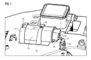
- FIG 1 illustrates a partial perspective view of a capacitor 10 arranged in a cooling channel 12 of a cooking oven according to a preferred embodiment of the present invention.
- the cooling channel 12 is arranged above an oven cavity of the cooking oven.
- the cooling channel 12 is made of plastics.
- the capacitor 10 is fastened in the cooling channel 12 by a fixing device.
- the fixing device includes a bedstop loop 14, a retaining loop 16, a front clip element 18 and a rear clip element 20.
- the bedstop loop 14, the retaining loop 16 and the front clip element 18 are integrated parts of the cooling channel 12.
- the rear clip element 20 is an integrated part of the bedstop loop 14.
- the rear clip element 20 is arranged in an upper part of the bedstop loop 14.
- the bedstop loop 14 and the retaining loop 16 enclose the capacitor 10.
- the capacitor 10 comprises two terminals 28.
- the terminals 28 are arranged at a front face side of the capacitor 10.
- a rear face side of the capacitor 10 is supported by the bedstop loop 14.
- the bedstop loop 14 encloses the capacitor 10 besides the rear face side of said capacitor 10.
- the retaining loop 16 encloses the capacitor 10 in a central portion of said capacitor 10.
- the front clip element 18 is directly arranged at the cooling channel 12.
- the front clip element 18 and the lower border of the front face side of the capacitor 10 form a snap-in mechanism.
- the rear clip element 20 at the bedstop loop 14 holds the capacitor 10.
- the rear clip element 20 prevents a vibration of the capacitor 10.
- the capacitor 10 is mounted by penetrating through the retaining loop 16 and inserting into the bedstop loop 14 along a direction from the right hand side to the left hand side in FIG 1 .
- the front clip element 18 prevents a removal of the capacitor 10 from the left hand side to the right hand side in FIG 1 .
- a spacer element 22 is arranged on the top side of the retaining loop 16.
- the spacer element 22 is an integrated part of the retaining loop 16 and extends upwards.
- the spacer element 22 prevents that a top wall of the cooking oven does get too close to or touches the capacitor 10.
- the spacer element 22 ensures that the top wall of the cooking oven has a minimum distance to the capacitor 10.
- a diode 24 is arranged besides the capacitor 10.
- the diode 24 is electrically connected to the capacitor 10 via one of the terminals 28.
- the diode 24 is mounted at a diode retainer 26, which is also an integrated part of the cooling channel 12.
- the diode retainer 26 includes a clip element. Said clip element and the diode 24 form a snap-in mechanism.
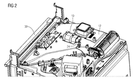
- FIG 2 illustrates a perspective view of the cooling channel 12 of the cooking oven according to the preferred embodiment of the present invention.
- FIG 2 clarifies the positions of the cooling channel 12, the capacitor 10 and the diode 24 inside the cooking oven.
- the cooling channel 12 is arranged above an oven cavity and behind a front panel 30 of the cooking oven.
- the fixing device ensures a predetermined position of the capacitor 10 in the cooling channel 12.
- the diode retainer 26 ensures a predetermined position of the diode 24.
- the fixing device improves the assembling of the cooling channel 12 and the cooking oven.
- the fixing device prevents damaging of the capacitor 10, the diode 24 and other parts.
- the diode retainer 26 prevents a damage of the diode 24 and other parts.
- the fixing device and/or the diode retainer 26 avoid noises.
Landscapes
- Engineering & Computer Science (AREA)
- Microelectronics & Electronic Packaging (AREA)
- Chemical & Material Sciences (AREA)
- Combustion & Propulsion (AREA)
- Mechanical Engineering (AREA)
- General Engineering & Computer Science (AREA)
- Cooling Or The Like Of Electrical Apparatus (AREA)
- Electric Ovens (AREA)
Abstract
Description
- The present invention relates to a cooling channel with a fixing device for a capacitor. In particular, the cooling channel is provided for a cooking oven. Further, the present invention relates to a cooking oven including a cooling channel.
- The cooling channel in a cooking oven is usually arranged above the oven cavity. Inside said cooling channel electric and/or electronic components are arranged. For example, a capacitor is fixed in the cooling channel by a bracket. For the production line there is not given any clear position of said capacitor in the cooling channel. If the capacitor is placed in an inappropriate position, then the cables or other part do not fit. Another problem may be a small gap between a top wall of the cooking oven and the capacitor below. Further, other electronic components like a diode may be damaged. Moreover, the wrong position of the capacitor may cause noises.
-
US 5,999,412 discloses a printed circuit board and a method for the precise assembly of electronic components on a surface of the printed circuit board. The electronic components are conductively attached at the printed circuit board by a reflow soldering technique. The printed circuit board comprises sections for receiving the electronic components on its surface. The sections are slotted contours or grooves. Said sections are shaped to secure that the electronic components are held in their desired positions after the application of solder paste. However, the printed circuit board requires the sections for receiving the electronic components, wherein the sizes and contours of said sections must be adapted to the electronic components. - It is an object of the present invention to provide a fixing device for a capacitor in the cooling channel of a cooking oven, which overcomes the problems mentioned above.
- The object of the present invention is achieved by the cooling channel according to claim 1.
- The present invention relates to a cooling channel with at least one fixing device for a capacitor, said cooling channel is provided for an appliance, in particular for a cooking oven, wherein
- the cooling channel is made of plastics and arranged or arrangeable in the appliance,
- the fixing device is an integrated part of the cooling channel,
- the fixing device includes a bedstop loop, a retaining loop and a front clip element,
- the bedstop loop is provided for supporting a rear face side of the capacitor and for enclosing said capacitor,
- the retaining loop is provided for enclosing the capacitor, and
- the front clip element is provided for forming a snap-in mechanism together with a border of a front face side of the capacitor.
- The main idea of the present invention is the fixing device as integrated part of the cooling channel, so that the capacitor is always placed in the predetermined position. The components of the fixing device, i.e. the bedstop loop, the retaining loop and the front clip element are integrated parts of the cooling channel. The bedstop loop and the retaining loop enclose the capacitor. The front clip element allows a fixation of the capacitor without any tools.
- In particular, the bedstop loop is provided for enclosing the capacitor beside the rear face side of the capacitor.
- In a similar way, the retaining loop is provided for enclosing a central portion of the capacitor.
- Further, the bedstop loop and/or the retaining loop may be provided for enclosing a curved surface area of the capacitor.
- Preferably, the front clip element is directly arranged at the cooling channel.
- Moreover, the bedstop loop may include a rear clip element provided for bearing against the curved surface area of the capacitor. Said rear clip element prevents vibrations of the capacitor.
- According to another aspect, the retaining loop includes at least one spacer element extending in an opposite direction to the cooling channel. The spacer element ensures that a top wall or side wall has a minimum distance to the capacitor.
- In particular, the capacitor is fastened or fixable by the fixing device by a partial penetrating through the retaining loop, an inserting into the bedstop loop and a snapping-in with the front clip element. The capacitor can be mounted by one movement of the hand.
- Further, the cooling channel may comprise a diode retainer provided for receiving at least one diode, wherein the at least one diode and the diode retainer form a snap-in mechanism.
- Also the diode retainer may be an integrated part of the cooling channel.
- Preferably, the diode retainer is arranged beside the fixing device.
- Furthermore, the present invention relates to a cooking oven including at least one cooling channel mentioned above.
- For example, the cooling channel is arranged or arrangeable between an oven cavity and a top wall of the cooking oven.
- Alternatively or additionally, the cooling channel is arranged or arrangeable between an oven cavity and a side wall of the cooking oven.
- The present invention will be described in further detail with reference to the drawing, in which
- FIG 1
- illustrates a partial perspective view of a capacitor arranged in a cooling channel of a cooking oven according to a preferred embodiment of the present invention, and
- FIG 2
- illustrates a perspective view of the cooling channel of the cooking oven according to the preferred embodiment of the present invention.
-
FIG 1 illustrates a partial perspective view of acapacitor 10 arranged in acooling channel 12 of a cooking oven according to a preferred embodiment of the present invention. - The
cooling channel 12 is arranged above an oven cavity of the cooking oven. Thecooling channel 12 is made of plastics. Thecapacitor 10 is fastened in thecooling channel 12 by a fixing device. The fixing device includes abedstop loop 14, aretaining loop 16, afront clip element 18 and arear clip element 20. Thebedstop loop 14, theretaining loop 16 and thefront clip element 18 are integrated parts of thecooling channel 12. Therear clip element 20 is an integrated part of thebedstop loop 14. Therear clip element 20 is arranged in an upper part of thebedstop loop 14. Thebedstop loop 14 and theretaining loop 16 enclose thecapacitor 10. - The
capacitor 10 comprises twoterminals 28. Theterminals 28 are arranged at a front face side of thecapacitor 10. A rear face side of thecapacitor 10 is supported by thebedstop loop 14. Further, thebedstop loop 14 encloses thecapacitor 10 besides the rear face side of saidcapacitor 10. Theretaining loop 16 encloses thecapacitor 10 in a central portion of saidcapacitor 10. Thefront clip element 18 is directly arranged at the coolingchannel 12. Thefront clip element 18 and the lower border of the front face side of thecapacitor 10 form a snap-in mechanism. Therear clip element 20 at thebedstop loop 14 holds thecapacitor 10. Therear clip element 20 prevents a vibration of thecapacitor 10. - The
capacitor 10 is mounted by penetrating through the retainingloop 16 and inserting into thebedstop loop 14 along a direction from the right hand side to the left hand side inFIG 1 . Thefront clip element 18 prevents a removal of thecapacitor 10 from the left hand side to the right hand side inFIG 1 . - A
spacer element 22 is arranged on the top side of the retainingloop 16. Thespacer element 22 is an integrated part of the retainingloop 16 and extends upwards. Thespacer element 22 prevents that a top wall of the cooking oven does get too close to or touches thecapacitor 10. Thespacer element 22 ensures that the top wall of the cooking oven has a minimum distance to thecapacitor 10. - A
diode 24 is arranged besides thecapacitor 10. Thediode 24 is electrically connected to thecapacitor 10 via one of theterminals 28. Thediode 24 is mounted at adiode retainer 26, which is also an integrated part of the coolingchannel 12. Thediode retainer 26 includes a clip element. Said clip element and thediode 24 form a snap-in mechanism. -
FIG 2 illustrates a perspective view of the coolingchannel 12 of the cooking oven according to the preferred embodiment of the present invention.FIG 2 clarifies the positions of the coolingchannel 12, thecapacitor 10 and thediode 24 inside the cooking oven. The coolingchannel 12 is arranged above an oven cavity and behind afront panel 30 of the cooking oven. - The fixing device according to the present invention ensures a predetermined position of the
capacitor 10 in the coolingchannel 12. In a similar way, thediode retainer 26 ensures a predetermined position of thediode 24. The fixing device improves the assembling of the coolingchannel 12 and the cooking oven. The fixing device prevents damaging of thecapacitor 10, thediode 24 and other parts. Also thediode retainer 26 prevents a damage of thediode 24 and other parts. The fixing device and/or thediode retainer 26 avoid noises. - Although an illustrative embodiment of the present invention has been described herein with reference to the accompanying drawings, it is to be understood that the present invention is not limited to that precise embodiment, and that various other changes and modifications may be affected therein by one skilled in the art without departing from the scope or spirit of the invention. All such changes and modifications are intended to be included within the scope of the invention as defined by the appended claims.
List of reference numerals 10 capacitor 12 cooling channel 14 bedstop loop 16 retaining loop 18 front clip element 20 rear clip element 22 spacer element 24 diode 26 diode retainer 28 terminal of the capacitor 30 front panel
Claims (14)
- A cooling channel (12) with at least one fixing device (14, 16, 18) for a capacitor (10), said cooling channel (12) is provided for an appliance, in particular for a cooking oven, wherein- the cooling channel (12) is made of plastics and arranged or arrangeable in the appliance,- the fixing device (14, 16, 18) is an integrated part of the cooling channel (12),- the fixing device includes a bedstop loop (14), a retaining loop (16) and a front clip element (18),- the bedstop loop (14) is provided for supporting a rear face side of the capacitor (10) and for enclosing said capacitor (10),- the retaining loop (16) is provided for enclosing the capacitor (10), and- the front clip element (18) is provided for forming a snap-in mechanism together with a border of a front face side of the capacitor (10).
- The cooling channel according to claim 1,
characterized in that
the bedstop loop (14) is provided for enclosing the capacitor (10) beside the rear face side of the capacitor (10). - The cooling channel according to claim 1 or 2,
characterized in that
the retaining loop (16) is provided for enclosing a central portion of the capacitor (10). - The cooling channel according to any one of the preceding claims,
characterized in that
the bedstop loop (14) and/or the retaining loop (16) are provided for enclosing a curved surface area of the capacitor (10). - The cooling channel according to any one of the preceding claims,
characterized in that
the front clip element (18) is directly arranged at the cooling channel (12). - The cooling channel according to any one of the preceding claims,
characterized in that
the bedstop loop (14) includes a rear clip element (20) provided for bearing against the curved surface area of the capacitor (10). - The cooling channel according to any one of the preceding claims,
characterized in that
the retaining loop (16) includes at least one spacer element (16) extending in an opposite direction to the cooling channel (12). - The cooling channel according to any one of the preceding claims,
characterized in that
the capacitor (10) is fastened or fixable by the fixing device by a partial penetrating through the retaining loop (16), an inserting into the bedstop loop (14) and a snapping-in with the front clip element (18). - The cooling channel according to any one of the preceding claims,
characterized in that
the cooling channel (12) comprises a diode retainer (26) provided for receiving at least one diode (24), wherein the at least one diode (24) and the diode retainer (26) form a snap-in mechanism. - The cooling channel according to claim 9,
characterized in that
the diode retainer (26) is an integrated part of the cooling channel (12). - The cooling channel according to claim 9 or 10,
characterized in that
the diode retainer (26) is arranged beside the fixing device (14, 16, 18). - A cooking oven including at least one cooling channel (12),
characterized in that
the cooking oven including at least one cooling channel (12) according to any one of the claims 1 to 11. - The cooking oven according to claim 12,
characterized in that
the cooling channel (12) is arranged or arrangeable between an oven cavity and a top wall of the cooking oven. - The cooking oven according to claim 12 or 13,
characterized in that
the cooling channel (12) is arranged or arrangeable between an oven cavity and a side wall of the cooking oven.
Priority Applications (1)
| Application Number | Priority Date | Filing Date | Title |
|---|---|---|---|
| EP13162655.8A EP2790477B1 (en) | 2013-04-08 | 2013-04-08 | A fixing device for a capacitor and a cooking oven including a cooling channel with the fixing device |
Applications Claiming Priority (1)
| Application Number | Priority Date | Filing Date | Title |
|---|---|---|---|
| EP13162655.8A EP2790477B1 (en) | 2013-04-08 | 2013-04-08 | A fixing device for a capacitor and a cooking oven including a cooling channel with the fixing device |
Publications (2)
| Publication Number | Publication Date |
|---|---|
| EP2790477A1 true EP2790477A1 (en) | 2014-10-15 |
| EP2790477B1 EP2790477B1 (en) | 2018-06-13 |
Family
ID=48045332
Family Applications (1)
| Application Number | Title | Priority Date | Filing Date |
|---|---|---|---|
| EP13162655.8A Not-in-force EP2790477B1 (en) | 2013-04-08 | 2013-04-08 | A fixing device for a capacitor and a cooking oven including a cooling channel with the fixing device |
Country Status (1)
| Country | Link |
|---|---|
| EP (1) | EP2790477B1 (en) |
Cited By (1)
| Publication number | Priority date | Publication date | Assignee | Title |
|---|---|---|---|---|
| EP4163940A1 (en) * | 2021-10-11 | 2023-04-12 | Veoneer Sweden AB | Mounting structure for a cylindrical capacitor |
Citations (2)
| Publication number | Priority date | Publication date | Assignee | Title |
|---|---|---|---|---|
| US5999412A (en) | 1996-03-18 | 1999-12-07 | Krone Aktiengesellschaft | Printed-circuit board and method for the precise assembly and soldering of electronic components on the surface of the printed-circuit board |
| US20110244712A1 (en) * | 2008-12-09 | 2011-10-06 | Kostal Kontakt Systeme Gmbh | Electrical appliance |
-
2013
- 2013-04-08 EP EP13162655.8A patent/EP2790477B1/en not_active Not-in-force
Patent Citations (2)
| Publication number | Priority date | Publication date | Assignee | Title |
|---|---|---|---|---|
| US5999412A (en) | 1996-03-18 | 1999-12-07 | Krone Aktiengesellschaft | Printed-circuit board and method for the precise assembly and soldering of electronic components on the surface of the printed-circuit board |
| US20110244712A1 (en) * | 2008-12-09 | 2011-10-06 | Kostal Kontakt Systeme Gmbh | Electrical appliance |
Cited By (1)
| Publication number | Priority date | Publication date | Assignee | Title |
|---|---|---|---|---|
| EP4163940A1 (en) * | 2021-10-11 | 2023-04-12 | Veoneer Sweden AB | Mounting structure for a cylindrical capacitor |
Also Published As
| Publication number | Publication date |
|---|---|
| EP2790477B1 (en) | 2018-06-13 |
Similar Documents
| Publication | Publication Date | Title |
|---|---|---|
| EP2629586A1 (en) | An induction cooking hob | |
| MY194142A (en) | Mounting structure for module in electronic device | |
| EP2750493A3 (en) | Cooling heat-generating electronics | |
| WO2003079743A3 (en) | Method for fitting out and soldering a circuit board, reflow oven and circuit board for said method | |
| US20130250540A1 (en) | Shielding shell | |
| US9113566B2 (en) | Electronic device and printed circuit board connection method | |
| EP2802196A2 (en) | Radiation shield standoff | |
| AU2014210119A1 (en) | An induction module for an induction cooking hob | |
| JP5728865B2 (en) | Heat dissipation mechanism and heat sink support bracket | |
| EP2285200A1 (en) | One-piece shielding hood with one or more pins | |
| EP2790477B1 (en) | A fixing device for a capacitor and a cooking oven including a cooling channel with the fixing device | |
| US8937813B2 (en) | Sub-rack mounting bracket and assembly | |
| CN102195191A (en) | Electric connector | |
| KR102425986B1 (en) | Electrical system with shielding | |
| CN101841093A (en) | shrapnel | |
| JP5550528B2 (en) | Circuit board assembly, connector, soldering method | |
| WO2017157527A1 (en) | Electrical device, having a housing part and a cover part | |
| WO2010123312A3 (en) | Fixing member for fixing shield case to printed circuit board | |
| JP2016134400A (en) | Electronics | |
| KR20160080668A (en) | Board connecting terminal button switch modules | |
| CN111954451B (en) | Board-level shielding cover | |
| JP2013211294A (en) | Shield case assembly | |
| CN103394788A (en) | Reflow oven guiding device | |
| WO2020022889A1 (en) | Grounding method for circuit board | |
| EP2733428A1 (en) | Cooking oven with a cooling channel |
Legal Events
| Date | Code | Title | Description |
|---|---|---|---|
| PUAI | Public reference made under article 153(3) epc to a published international application that has entered the european phase |
Free format text: ORIGINAL CODE: 0009012 |
|
| 17P | Request for examination filed |
Effective date: 20130408 |
|
| AK | Designated contracting states |
Kind code of ref document: A1 Designated state(s): AL AT BE BG CH CY CZ DE DK EE ES FI FR GB GR HR HU IE IS IT LI LT LU LV MC MK MT NL NO PL PT RO RS SE SI SK SM TR |
|
| AX | Request for extension of the european patent |
Extension state: BA ME |
|
| R17P | Request for examination filed (corrected) |
Effective date: 20150331 |
|
| RBV | Designated contracting states (corrected) |
Designated state(s): AL AT BE BG CH CY CZ DE DK EE ES FI FR GB GR HR HU IE IS IT LI LT LU LV MC MK MT NL NO PL PT RO RS SE SI SK SM TR |
|
| GRAP | Despatch of communication of intention to grant a patent |
Free format text: ORIGINAL CODE: EPIDOSNIGR1 |
|
| STAA | Information on the status of an ep patent application or granted ep patent |
Free format text: STATUS: GRANT OF PATENT IS INTENDED |
|
| INTG | Intention to grant announced |
Effective date: 20180104 |
|
| RAP1 | Party data changed (applicant data changed or rights of an application transferred) |
Owner name: ELECTROLUX APPLIANCES AKTIEBOLAG |
|
| GRAS | Grant fee paid |
Free format text: ORIGINAL CODE: EPIDOSNIGR3 |
|
| GRAA | (expected) grant |
Free format text: ORIGINAL CODE: 0009210 |
|
| STAA | Information on the status of an ep patent application or granted ep patent |
Free format text: STATUS: THE PATENT HAS BEEN GRANTED |
|
| AK | Designated contracting states |
Kind code of ref document: B1 Designated state(s): AL AT BE BG CH CY CZ DE DK EE ES FI FR GB GR HR HU IE IS IT LI LT LU LV MC MK MT NL NO PL PT RO RS SE SI SK SM TR |
|
| REG | Reference to a national code |
Ref country code: GB Ref legal event code: FG4D |
|
| REG | Reference to a national code |
Ref country code: CH Ref legal event code: EP Ref country code: AT Ref legal event code: REF Ref document number: 1009886 Country of ref document: AT Kind code of ref document: T Effective date: 20180615 |
|
| REG | Reference to a national code |
Ref country code: IE Ref legal event code: FG4D |
|
| REG | Reference to a national code |
Ref country code: DE Ref legal event code: R096 Ref document number: 602013038786 Country of ref document: DE |
|
| REG | Reference to a national code |
Ref country code: NL Ref legal event code: MP Effective date: 20180613 |
|
| REG | Reference to a national code |
Ref country code: LT Ref legal event code: MG4D |
|
| PG25 | Lapsed in a contracting state [announced via postgrant information from national office to epo] |
Ref country code: SE Free format text: LAPSE BECAUSE OF FAILURE TO SUBMIT A TRANSLATION OF THE DESCRIPTION OR TO PAY THE FEE WITHIN THE PRESCRIBED TIME-LIMIT Effective date: 20180613 Ref country code: ES Free format text: LAPSE BECAUSE OF FAILURE TO SUBMIT A TRANSLATION OF THE DESCRIPTION OR TO PAY THE FEE WITHIN THE PRESCRIBED TIME-LIMIT Effective date: 20180613 Ref country code: LT Free format text: LAPSE BECAUSE OF FAILURE TO SUBMIT A TRANSLATION OF THE DESCRIPTION OR TO PAY THE FEE WITHIN THE PRESCRIBED TIME-LIMIT Effective date: 20180613 Ref country code: NO Free format text: LAPSE BECAUSE OF FAILURE TO SUBMIT A TRANSLATION OF THE DESCRIPTION OR TO PAY THE FEE WITHIN THE PRESCRIBED TIME-LIMIT Effective date: 20180913 Ref country code: BG Free format text: LAPSE BECAUSE OF FAILURE TO SUBMIT A TRANSLATION OF THE DESCRIPTION OR TO PAY THE FEE WITHIN THE PRESCRIBED TIME-LIMIT Effective date: 20180913 Ref country code: FI Free format text: LAPSE BECAUSE OF FAILURE TO SUBMIT A TRANSLATION OF THE DESCRIPTION OR TO PAY THE FEE WITHIN THE PRESCRIBED TIME-LIMIT Effective date: 20180613 Ref country code: CY Free format text: LAPSE BECAUSE OF FAILURE TO SUBMIT A TRANSLATION OF THE DESCRIPTION OR TO PAY THE FEE WITHIN THE PRESCRIBED TIME-LIMIT Effective date: 20180613 |
|
| PG25 | Lapsed in a contracting state [announced via postgrant information from national office to epo] |
Ref country code: HR Free format text: LAPSE BECAUSE OF FAILURE TO SUBMIT A TRANSLATION OF THE DESCRIPTION OR TO PAY THE FEE WITHIN THE PRESCRIBED TIME-LIMIT Effective date: 20180613 Ref country code: RS Free format text: LAPSE BECAUSE OF FAILURE TO SUBMIT A TRANSLATION OF THE DESCRIPTION OR TO PAY THE FEE WITHIN THE PRESCRIBED TIME-LIMIT Effective date: 20180613 Ref country code: GR Free format text: LAPSE BECAUSE OF FAILURE TO SUBMIT A TRANSLATION OF THE DESCRIPTION OR TO PAY THE FEE WITHIN THE PRESCRIBED TIME-LIMIT Effective date: 20180914 Ref country code: LV Free format text: LAPSE BECAUSE OF FAILURE TO SUBMIT A TRANSLATION OF THE DESCRIPTION OR TO PAY THE FEE WITHIN THE PRESCRIBED TIME-LIMIT Effective date: 20180613 |
|
| REG | Reference to a national code |
Ref country code: AT Ref legal event code: MK05 Ref document number: 1009886 Country of ref document: AT Kind code of ref document: T Effective date: 20180613 |
|
| PG25 | Lapsed in a contracting state [announced via postgrant information from national office to epo] |
Ref country code: NL Free format text: LAPSE BECAUSE OF FAILURE TO SUBMIT A TRANSLATION OF THE DESCRIPTION OR TO PAY THE FEE WITHIN THE PRESCRIBED TIME-LIMIT Effective date: 20180613 |
|
| PG25 | Lapsed in a contracting state [announced via postgrant information from national office to epo] |
Ref country code: AT Free format text: LAPSE BECAUSE OF FAILURE TO SUBMIT A TRANSLATION OF THE DESCRIPTION OR TO PAY THE FEE WITHIN THE PRESCRIBED TIME-LIMIT Effective date: 20180613 Ref country code: IS Free format text: LAPSE BECAUSE OF FAILURE TO SUBMIT A TRANSLATION OF THE DESCRIPTION OR TO PAY THE FEE WITHIN THE PRESCRIBED TIME-LIMIT Effective date: 20181013 Ref country code: EE Free format text: LAPSE BECAUSE OF FAILURE TO SUBMIT A TRANSLATION OF THE DESCRIPTION OR TO PAY THE FEE WITHIN THE PRESCRIBED TIME-LIMIT Effective date: 20180613 Ref country code: SK Free format text: LAPSE BECAUSE OF FAILURE TO SUBMIT A TRANSLATION OF THE DESCRIPTION OR TO PAY THE FEE WITHIN THE PRESCRIBED TIME-LIMIT Effective date: 20180613 Ref country code: RO Free format text: LAPSE BECAUSE OF FAILURE TO SUBMIT A TRANSLATION OF THE DESCRIPTION OR TO PAY THE FEE WITHIN THE PRESCRIBED TIME-LIMIT Effective date: 20180613 Ref country code: CZ Free format text: LAPSE BECAUSE OF FAILURE TO SUBMIT A TRANSLATION OF THE DESCRIPTION OR TO PAY THE FEE WITHIN THE PRESCRIBED TIME-LIMIT Effective date: 20180613 Ref country code: PL Free format text: LAPSE BECAUSE OF FAILURE TO SUBMIT A TRANSLATION OF THE DESCRIPTION OR TO PAY THE FEE WITHIN THE PRESCRIBED TIME-LIMIT Effective date: 20180613 |
|
| PG25 | Lapsed in a contracting state [announced via postgrant information from national office to epo] |
Ref country code: SM Free format text: LAPSE BECAUSE OF FAILURE TO SUBMIT A TRANSLATION OF THE DESCRIPTION OR TO PAY THE FEE WITHIN THE PRESCRIBED TIME-LIMIT Effective date: 20180613 |
|
| REG | Reference to a national code |
Ref country code: DE Ref legal event code: R097 Ref document number: 602013038786 Country of ref document: DE |
|
| PLBE | No opposition filed within time limit |
Free format text: ORIGINAL CODE: 0009261 |
|
| STAA | Information on the status of an ep patent application or granted ep patent |
Free format text: STATUS: NO OPPOSITION FILED WITHIN TIME LIMIT |
|
| 26N | No opposition filed |
Effective date: 20190314 |
|
| PG25 | Lapsed in a contracting state [announced via postgrant information from national office to epo] |
Ref country code: DK Free format text: LAPSE BECAUSE OF FAILURE TO SUBMIT A TRANSLATION OF THE DESCRIPTION OR TO PAY THE FEE WITHIN THE PRESCRIBED TIME-LIMIT Effective date: 20180613 Ref country code: SI Free format text: LAPSE BECAUSE OF FAILURE TO SUBMIT A TRANSLATION OF THE DESCRIPTION OR TO PAY THE FEE WITHIN THE PRESCRIBED TIME-LIMIT Effective date: 20180613 |
|
| PG25 | Lapsed in a contracting state [announced via postgrant information from national office to epo] |
Ref country code: AL Free format text: LAPSE BECAUSE OF FAILURE TO SUBMIT A TRANSLATION OF THE DESCRIPTION OR TO PAY THE FEE WITHIN THE PRESCRIBED TIME-LIMIT Effective date: 20180613 |
|
| REG | Reference to a national code |
Ref country code: CH Ref legal event code: PL |
|
| REG | Reference to a national code |
Ref country code: BE Ref legal event code: MM Effective date: 20190430 |
|
| GBPC | Gb: european patent ceased through non-payment of renewal fee |
Effective date: 20190408 |
|
| PG25 | Lapsed in a contracting state [announced via postgrant information from national office to epo] |
Ref country code: LU Free format text: LAPSE BECAUSE OF NON-PAYMENT OF DUE FEES Effective date: 20190408 Ref country code: MC Free format text: LAPSE BECAUSE OF FAILURE TO SUBMIT A TRANSLATION OF THE DESCRIPTION OR TO PAY THE FEE WITHIN THE PRESCRIBED TIME-LIMIT Effective date: 20180613 |
|
| PG25 | Lapsed in a contracting state [announced via postgrant information from national office to epo] |
Ref country code: LI Free format text: LAPSE BECAUSE OF NON-PAYMENT OF DUE FEES Effective date: 20190430 Ref country code: GB Free format text: LAPSE BECAUSE OF NON-PAYMENT OF DUE FEES Effective date: 20190408 Ref country code: CH Free format text: LAPSE BECAUSE OF NON-PAYMENT OF DUE FEES Effective date: 20190430 |
|
| PG25 | Lapsed in a contracting state [announced via postgrant information from national office to epo] |
Ref country code: BE Free format text: LAPSE BECAUSE OF NON-PAYMENT OF DUE FEES Effective date: 20190430 Ref country code: FR Free format text: LAPSE BECAUSE OF NON-PAYMENT OF DUE FEES Effective date: 20190430 |
|
| PG25 | Lapsed in a contracting state [announced via postgrant information from national office to epo] |
Ref country code: TR Free format text: LAPSE BECAUSE OF FAILURE TO SUBMIT A TRANSLATION OF THE DESCRIPTION OR TO PAY THE FEE WITHIN THE PRESCRIBED TIME-LIMIT Effective date: 20180613 |
|
| PG25 | Lapsed in a contracting state [announced via postgrant information from national office to epo] |
Ref country code: IE Free format text: LAPSE BECAUSE OF NON-PAYMENT OF DUE FEES Effective date: 20190408 |
|
| PG25 | Lapsed in a contracting state [announced via postgrant information from national office to epo] |
Ref country code: PT Free format text: LAPSE BECAUSE OF FAILURE TO SUBMIT A TRANSLATION OF THE DESCRIPTION OR TO PAY THE FEE WITHIN THE PRESCRIBED TIME-LIMIT Effective date: 20181015 |
|
| PGFP | Annual fee paid to national office [announced via postgrant information from national office to epo] |
Ref country code: DE Payment date: 20200420 Year of fee payment: 8 |
|
| PGFP | Annual fee paid to national office [announced via postgrant information from national office to epo] |
Ref country code: IT Payment date: 20200428 Year of fee payment: 8 |
|
| PG25 | Lapsed in a contracting state [announced via postgrant information from national office to epo] |
Ref country code: HU Free format text: LAPSE BECAUSE OF FAILURE TO SUBMIT A TRANSLATION OF THE DESCRIPTION OR TO PAY THE FEE WITHIN THE PRESCRIBED TIME-LIMIT; INVALID AB INITIO Effective date: 20130408 Ref country code: MT Free format text: LAPSE BECAUSE OF FAILURE TO SUBMIT A TRANSLATION OF THE DESCRIPTION OR TO PAY THE FEE WITHIN THE PRESCRIBED TIME-LIMIT Effective date: 20180613 |
|
| REG | Reference to a national code |
Ref country code: DE Ref legal event code: R119 Ref document number: 602013038786 Country of ref document: DE |
|
| PG25 | Lapsed in a contracting state [announced via postgrant information from national office to epo] |
Ref country code: DE Free format text: LAPSE BECAUSE OF NON-PAYMENT OF DUE FEES Effective date: 20211103 |
|
| PG25 | Lapsed in a contracting state [announced via postgrant information from national office to epo] |
Ref country code: MK Free format text: LAPSE BECAUSE OF FAILURE TO SUBMIT A TRANSLATION OF THE DESCRIPTION OR TO PAY THE FEE WITHIN THE PRESCRIBED TIME-LIMIT Effective date: 20180613 |
|
| PG25 | Lapsed in a contracting state [announced via postgrant information from national office to epo] |
Ref country code: IT Free format text: LAPSE BECAUSE OF NON-PAYMENT OF DUE FEES Effective date: 20200408 |
|
| PG25 | Lapsed in a contracting state [announced via postgrant information from national office to epo] |
Ref country code: IT Free format text: LAPSE BECAUSE OF NON-PAYMENT OF DUE FEES Effective date: 20210408 |