EP2790476B1 - Multilayer printed circuit board and manufacturing method thereof - Google Patents
Multilayer printed circuit board and manufacturing method thereof Download PDFInfo
- Publication number
- EP2790476B1 EP2790476B1 EP12871458.1A EP12871458A EP2790476B1 EP 2790476 B1 EP2790476 B1 EP 2790476B1 EP 12871458 A EP12871458 A EP 12871458A EP 2790476 B1 EP2790476 B1 EP 2790476B1
- Authority
- EP
- European Patent Office
- Prior art keywords
- metal column
- layer
- core plate
- mechanical part
- disposed
- Prior art date
- Legal status (The legal status is an assumption and is not a legal conclusion. Google has not performed a legal analysis and makes no representation as to the accuracy of the status listed.)
- Active
Links
Images


Classifications
-
- H—ELECTRICITY
- H05—ELECTRIC TECHNIQUES NOT OTHERWISE PROVIDED FOR
- H05K—PRINTED CIRCUITS; CASINGS OR CONSTRUCTIONAL DETAILS OF ELECTRIC APPARATUS; MANUFACTURE OF ASSEMBLAGES OF ELECTRICAL COMPONENTS
- H05K1/00—Printed circuits
- H05K1/02—Details
- H05K1/11—Printed elements for providing electric connections to or between printed circuits
- H05K1/115—Via connections; Lands around holes or via connections
-
- H—ELECTRICITY
- H05—ELECTRIC TECHNIQUES NOT OTHERWISE PROVIDED FOR
- H05K—PRINTED CIRCUITS; CASINGS OR CONSTRUCTIONAL DETAILS OF ELECTRIC APPARATUS; MANUFACTURE OF ASSEMBLAGES OF ELECTRICAL COMPONENTS
- H05K1/00—Printed circuits
- H05K1/02—Details
- H05K1/14—Structural association of two or more printed circuits
- H05K1/144—Stacked arrangements of planar printed circuit boards
-
- H—ELECTRICITY
- H05—ELECTRIC TECHNIQUES NOT OTHERWISE PROVIDED FOR
- H05K—PRINTED CIRCUITS; CASINGS OR CONSTRUCTIONAL DETAILS OF ELECTRIC APPARATUS; MANUFACTURE OF ASSEMBLAGES OF ELECTRICAL COMPONENTS
- H05K3/00—Apparatus or processes for manufacturing printed circuits
- H05K3/40—Forming printed elements for providing electric connections to or between printed circuits
- H05K3/4038—Through-connections; Vertical interconnect access [VIA] connections
- H05K3/4046—Through-connections; Vertical interconnect access [VIA] connections using auxiliary conductive elements, e.g. metallic spheres, eyelets, pieces of wire
-
- H—ELECTRICITY
- H05—ELECTRIC TECHNIQUES NOT OTHERWISE PROVIDED FOR
- H05K—PRINTED CIRCUITS; CASINGS OR CONSTRUCTIONAL DETAILS OF ELECTRIC APPARATUS; MANUFACTURE OF ASSEMBLAGES OF ELECTRICAL COMPONENTS
- H05K3/00—Apparatus or processes for manufacturing printed circuits
- H05K3/46—Manufacturing multilayer circuits
- H05K3/4611—Manufacturing multilayer circuits by laminating two or more circuit boards
- H05K3/4623—Manufacturing multilayer circuits by laminating two or more circuit boards the circuit boards having internal via connections between two or more circuit layers before lamination, e.g. double-sided circuit boards
-
- H—ELECTRICITY
- H05—ELECTRIC TECHNIQUES NOT OTHERWISE PROVIDED FOR
- H05K—PRINTED CIRCUITS; CASINGS OR CONSTRUCTIONAL DETAILS OF ELECTRIC APPARATUS; MANUFACTURE OF ASSEMBLAGES OF ELECTRICAL COMPONENTS
- H05K1/00—Printed circuits
- H05K1/02—Details
- H05K1/0213—Electrical arrangements not otherwise provided for
- H05K1/0237—High frequency adaptations
- H05K1/025—Impedance arrangements, e.g. impedance matching, reduction of parasitic impedance
- H05K1/0251—Impedance arrangements, e.g. impedance matching, reduction of parasitic impedance related to vias or transitions between vias and transmission lines
-
- H—ELECTRICITY
- H05—ELECTRIC TECHNIQUES NOT OTHERWISE PROVIDED FOR
- H05K—PRINTED CIRCUITS; CASINGS OR CONSTRUCTIONAL DETAILS OF ELECTRIC APPARATUS; MANUFACTURE OF ASSEMBLAGES OF ELECTRICAL COMPONENTS
- H05K2201/00—Indexing scheme relating to printed circuits covered by H05K1/00
- H05K2201/10—Details of components or other objects attached to or integrated in a printed circuit board
- H05K2201/10227—Other objects, e.g. metallic pieces
- H05K2201/10242—Metallic cylinders
-
- H—ELECTRICITY
- H05—ELECTRIC TECHNIQUES NOT OTHERWISE PROVIDED FOR
- H05K—PRINTED CIRCUITS; CASINGS OR CONSTRUCTIONAL DETAILS OF ELECTRIC APPARATUS; MANUFACTURE OF ASSEMBLAGES OF ELECTRICAL COMPONENTS
- H05K3/00—Apparatus or processes for manufacturing printed circuits
- H05K3/46—Manufacturing multilayer circuits
- H05K3/4611—Manufacturing multilayer circuits by laminating two or more circuit boards
- H05K3/4614—Manufacturing multilayer circuits by laminating two or more circuit boards the electrical connections between the circuit boards being made during lamination
- H05K3/4617—Manufacturing multilayer circuits by laminating two or more circuit boards the electrical connections between the circuit boards being made during lamination characterized by laminating only or mainly similar single-sided circuit boards
-
- H—ELECTRICITY
- H05—ELECTRIC TECHNIQUES NOT OTHERWISE PROVIDED FOR
- H05K—PRINTED CIRCUITS; CASINGS OR CONSTRUCTIONAL DETAILS OF ELECTRIC APPARATUS; MANUFACTURE OF ASSEMBLAGES OF ELECTRICAL COMPONENTS
- H05K3/00—Apparatus or processes for manufacturing printed circuits
- H05K3/46—Manufacturing multilayer circuits
- H05K3/4644—Manufacturing multilayer circuits by building the multilayer layer by layer, i.e. build-up multilayer circuits
- H05K3/4647—Manufacturing multilayer circuits by building the multilayer layer by layer, i.e. build-up multilayer circuits by applying an insulating layer around previously made via studs
Landscapes
- Engineering & Computer Science (AREA)
- Microelectronics & Electronic Packaging (AREA)
- Manufacturing & Machinery (AREA)
- Production Of Multi-Layered Print Wiring Board (AREA)
Description
- The present invention relates to the field of electronics, and in particular, to a multi-layer printed circuit board and a method for fabricating a multi-layer printed circuit board.
- Currently, a conventional printed circuit board fabrication technique is commonly used to fabricate an antenna feeder PCB (Printed Circuit Board, printed circuit board), and in particular, a conventional polytetrafluorethylene (polytetrafluorethylene, PTFE for short) printed circuit board is used.
- Conductor roughness of a transmission path in an antenna feeder circuit is one of major factors affecting passive inter-modulation (Passive Inter-Modulation, PIM for short) of an antenna; therefore, transmission lines at internal and external layers both use copper foil of low roughness to improve PIM. A transmission line at an internal layer of a conventional multi-layer PTFE board is connected to a surface layer through a plated hole, and a current is transmitted in a direction along an interior wall of the plated hole; however, roughness of the wall of the plated hole affects PIM performance of the antenna feeder circuit.
- On the one hand, a plated hole fabrication technique inevitably brings about a problem such as a rough hole and copper infiltration, which greatly affects PIM performance; and on the other hand, a surplus wall of the plated hole also affects signal matching. To solve the foregoing problems, the prior art provides a method for connecting a line at an internal layer and a line at an external layer by means of welding. However, in this method, solder is used and occupies large space. In addition, this method is not suitable for mass production because of low welding efficiency.
-
EP0564019 discloses a multilayer microelectronics module formed by laminating together individual thermoplastic polymer sheets formed by injection, compression or other suitable molding techniques. -
US2006/0272850 discloses an interlayer connection conductor is formed of a substantially spherical interlayer connector that is formed by forced in through holes, in a thickness direction, on a flexible printed circuit board having wiring layers on at least one surface of an insulating layer. -
US5,876,789 discloses that, in a first step, a conductive layer is formed on a three-dimensionally curved upper surface of a main mold, in a second step, a peripheral surface mold is attached to the outer peripheral surface of the main mold, and a liquid dielectric of an age hardening type is cast onto the conductor layer, and hardened, in a third step, the peripheral surface mold is detached from the main mold, and an unnecessary portion of the hardened dielectric is cut to thereby form a dielectric layer, in a fourth step, another conductor layer is formed on the dielectric layer. -
US2009/0175022 discloses a method for allowing an easier electric connection between layers of a multi-layer package structure using a metal pin fabricated based on semiconductor device processes. - Various aspects and embodiments of the present invention are set out in the appended claims.
- To describe the technical solutions in the embodiments of the present invention or in the prior art more clearly, the following briefly introduces the accompanying drawings required for describing the embodiments or the prior art. Apparently, the accompanying drawings in the following description show merely some embodiments of the present invention, and a person of ordinary skill in the art may still derive other drawings from these accompanying drawings without creative efforts.
-
FIG. 1 is a schematic structural diagram of an antenna feeder printed circuit board according to an embodiment of the present invention; -
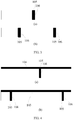
FIG. 2 to FIG. 4 are schematic structural diagrams of a process of a method for fabricating an antenna feeder printed circuit board according to an embodiment of the present invention; and -
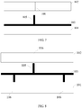
FIG. 5 to FIG. 8 are schematic structural diagrams of a process of another method for fabricating an antenna feeder printed circuit board according to an embodiment of the present invention. - The following clearly and completely describes the technical solutions in the embodiments of the present invention with reference to the accompanying drawings in the embodiments of the present invention. Apparently, the described embodiments are merely a part rather than all of the embodiments of the present invention. Other embodiments obtained by a person of ordinary skill in the art based on the embodiments of the present invention may fall within the protection scope of the present invention which is defined by the claims. An embodiment of the present invention provides a multi-layer printed
circuit board 10. As shown inFIG. 1 , the multi-layer printed circuit board includes at least two layers of core plates that are adhered, which are acore plate 101 and acore plate 102 in this embodiment, where a first circuitmechanical part 103 is disposed on thecore plate 101; a second circuitmechanical part 104 is disposed on thecore plate 102; and avia 106 is provided on thecore plate 101 and thecore plate 102. The multi-layer printedcircuit board 10 further includes: - a
metal column 105 embedded in thevia 106, where one end of themetal column 105 is connected to a corresponding position on the first circuitmechanical part 103 disposed on thecore plate 101 at a current layer, and the other end of themetal column 105 is connected to a corresponding position on the second circuitmechanical part 104 disposed on thecore plate 102 at an adjacent layer. In this way, a transmission line at an internal layer of a multi-layer board is connected by using a metal column. In comparison with the prior art in which a connection is performed through a plated hole, a problem that signal transmission performance is affected by a rough wall of a plated hole is avoided, and a problem that signal matching is affected by a surplus wall of a plated hole is also avoided. - Specifically, a material of the
metal column 105 may be copper, aluminum, or another metal material. - Preferably, a surface of the
metal column 105 is disposed with a non-magnetic metal layer, and specifically, the so-called non-magnetic metal refers to non-magnetic metal other than steel, nickel metal, and a part of stainless steel (a martensite or ferrite type, such as 404B, 430, 420, or 410). Exemplarily, the surface of themetal column 105 may be processed with a material such as gold, silver, or tin. In this way, conductive contact impedance can be effectively improved, and signal transmission is enhanced, thereby ensuring reliability of signal transmission. A surface side of themetal column 105 that is in contact with thevia 106 is disposed with a medium protection layer, where the medium protection layer is plastic, paint, or the like, so as to protect the metal column more effectively against oxidization or corrosion in long-term use and further ensure reliability of signal transmission. - In the multi-layer printed circuit board provided by the embodiment of the present invention, a metal column is used to connect circuit mechanical parts of adjacent core plates, In comparison with the prior art in which circuit mechanical parts of adjacent core plates are connected through a plated hole, a problem that signal transmission performance is affected by a rough wall of a plated hole or the like is avoided.
- An embodiment of the present invention provides a method for fabricating a multi-layer printed circuit board. As shown in
FIG. 2 to FIG. 4 , the method includes: - S201: Provide a via on a fabricated core plate.
- Specifically, in the embodiment of the present invention, a
via 106 is provided at a position where a first circuitmechanical part 103 of acore plate 101 at a current layer is connected to a second circuitmechanical part 104 of acore plate 102 at an adjacent layer. As shown inFIG. 2 , (a) shows the core plate at the current layer, where one via 106 is provided on the core plate at the layer, and (b) shows the core plate at the adjacent layer, where twovias 106 are provided on the core plate at the adjacent layer. Exemplarily, the core plate may be a thermoplastic resin core plate, and thevia 106 may be made by means of hole drilling or hole milling. - S202: Press a fabricated metal column into the via.
- Specifically, as shown in
FIG. 3 , a material of themetal column 105 may be copper, aluminum, or another metal material. Moreover, themetal column 105 may be formed by means of a die-casting or machining technique, where the die-casting technique is a method for casting and liquid die forging. A die-casting and die forging technique is a technique that is completed on a dedicated die-casting and die forging machine, and a basic technique process of the die-casting and die forging technique is: Metal liquid is first cast and mold-filled into a cavity of a mold at a low or high speed, where the mold has a movable cavity surface, and the cavity surface is pressurized and forged in a cooling process of the metal liquid, so that defects of shrinkage cavity and shrinkage porosity of a blank are eliminated, and an internal structure of the blank obtains fragmented grains in a forging state. Comprehensive mechanical performance of the blank can be significantly improved. The machining is short for mechanical processing, and refers to a processing technique for precisely removing a material by using a processing machine. - Preferably, a surface of the
metal column 105 is disposed with a non-magnetic metal layer, and specifically, the so-called non-magnetic metal refers to non-magnetic metal other than steel, nickel metal, and a part of stainless steel (a martensite or ferrite type: such as 404B, 430, 420, or 410) metal. Exemplarily, the surface of themetal column 105 may be processed with a material such as gold, silver, or tin. In this way, conductive contact impedance can be effectively improved, and signal transmission is enhanced, thereby ensuring reliability of signal transmission. The prior art may be used for disposing the non-magnetic metal layer on the surface of themetal column 105, which is not repeatedly described herein. A surface of themetal column 105 that is in contact with thevia 106 is disposed with a medium protection layer, where the medium protection layer may be specifically plastic, paint, or the like. Exemplarily, a structure of the metal column is similar to that of a coaxial line. It should be noted that themetal column 105 may be pressed into thevia 106 manually or by using an automatic chip mounter. After themetal column 105 is pressed into thevia 106, a certain holding force is required between themetal column 105 and thevia 106, so as to prevent themetal column 105 from dropping off. - S203: Laminate core plates at various layers that are configured with a circuit mechanical part, so that one end of the metal column is connected to a corresponding position on a first circuit mechanical part disposed on a core plate at a current layer, and the other end of the metal column is connected to a corresponding position on a second circuit mechanical part disposed on a core plate at an adjacent layer.
- Specifically, in this embodiment, as shown in
FIG. 4 , theadjacent core plates FIG. 1 . The first circuitmechanical part 103 on thecore plate 101 at the current layer is connected to the second circuitmechanical part 104 on thecore plate 102 at the adjacent layer by using themetal column 105. Further, the circuit mechanical parts that are formed on the core plates by means of etching may be formed before the metal column is pressed into the via106, or may also be formed after the metal column is pressed into thevia 106. - Exemplarily, the circuit mechanical parts may be antenna feeder circuit mechanical parts, and are connected to adjacent antenna feeder circuit mechanical parts by using a metal column embedded in a core plate. In this way, a current between the adjacent antenna feeder circuit mechanical parts is transmitted in a direction along the metal column. In comparison with the prior art in which a current is transmitted in a direction along a plated hole, a problem that signal matching is affected by a rough wall of a plated hole is avoided, and PIM performance of an antenna feeder circuit is also improved.
- Preferably, after fabrication according to the method provided by this embodiment, multiple layers of core plates need to be laminated. The multiple core plates may be first disposed, aligned in a manner such as by using dowels, and then laminated. In this way, a phenomenon of dislocation occurring at a position where a metal column is connected to a circuit mechanical part as a result of multi-layer lamination is prevented. Specifically, the multiple core plates that are disposed may be laminated by using a high-temperature press. The metal column is directly connected to circuits at another layer; and an external layer of a copper column can be directly welded, or connected to another circuit by means of electroplating.
- In the method for fabricating a multi-layer printed circuit board provided by the embodiment of the present invention, a metal column is used to connect circuit mechanical parts of adjacent core plates. In comparison with the prior art in which circuit mechanical parts of adjacent core plates are connected through a plated hole, a problem that signal transmission performance is affected by a rough wall of a plated hole or the like is avoided. In addition, the fabrication method is simple, and is very suitable for mass production.
- An embodiment of the present invention provides a method for fabricating a multi-layer printed circuit board. As shown in
FIG. 5 to FIG. 8 , the method includes: - S501: Form, on a first circuit mechanical part of a core plate at a current layer, a metal column that is used to connect to a second circuit mechanical part of a core plate at an adjacent layer and is perpendicular to the first circuit mechanical part.
- Specifically, a circuit mechanical part with a metal column may be fabricated in a manner, such as die stamping or laser cutting. A material of the circuit mechanical part and a material of the metal column are copper, aluminum, or other metal. Exemplarily, as shown in
FIG. 5 , a structural top view of a first circuitmechanical part 103 on acore plate 101 at a current layer is shown inFIG. 5(a) , and a side view is shown inFIG. 5(b) , where a metal column is marked with 105. - Preferably, a surface of the
metal column 105 is disposed with a non-magnetic metal layer, and specifically, the so-called non-magnetic metal refers to non-magnetic metal other than steel, nickel metal, and a part of stainless steel (martensite or ferrite type: such as 404B, 430, 420, and 410) metal. Exemplarily, the surface of themetal column 105 may be processed with a material such as gold, silver, or tin. In this way, conductive contact impedance can be effectively improved, and signal transmission is enhanced, thereby ensuring reliability of signal transmission. The prior art may be used for disposing the non-magnetic metal layer on the surface of themetal column 105, which is not repeatedly described herein. A surface of the metal column that is in contact with a via 106 is disposed with a medium protection layer, where the medium protection layer may be specifically plastic, paint, or the like. Exemplarily, a structure of the metal column is similar to that of a coaxial line.
S502: If the metal column points to the core plate at the current layer, provide a via at a corresponding position on the core plate at the current layer; and/or, if the metal column points to the core plate at the adjacent layer, provide a via at a corresponding position on the core plate at the adjacent layer. - Specifically, if the
metal column 105 on the first circuitmechanical part 103 points to thecore plate 101 at the current layer, a via 106 is provided at a corresponding position on the core plate at the current layer, as shown inFIG. 6 .
If themetal column 105 on the first circuitmechanical part 103 points to the core plate at the adjacent layer, a via 106 is provided at a corresponding position on the core plate at the adjacent layer, as shown inFIG. 7 . - If a
metal column 105 on the first circuitmechanical part 103 points to thecore plate 102 at the adjacent layer, and anothermetal column 105 points to thecore plate 101 at the current layer, a via 106 is provided at each of corresponding positions on the core plate at the adjacent layer and the core plate at the current layer, as shown inFIG. 8 . - Exemplarily, the core plate may be a thermoplastic resin core plate, and the via may be made by means of hole drilling or hole milling.
- S503: Laminate core plates at various layers that are configured with a circuit mechanical part, so that one end of the metal column is connected to a corresponding position on the first circuit mechanical part disposed on the core plate at the current layer, and the other end of the metal column is connected to a corresponding position on the second circuit mechanical part disposed on the core plate at the adjacent layer.
- Specifically, after the fabricated circuit mechanical parts are disposed on the core plates, the core plates at various layers are laminated, so as to form the multi-layer printed circuit board shown in
FIG. 1 , where the metal column is correspondingly pressed into the via, so that one end of the metal column is connected to the corresponding position on the first circuit mechanical part disposed on the core plate at the current layer, and the other end of the metal column is connected to the corresponding position on the second circuit mechanical part disposed on the core plate at the adjacent layer. - Exemplarily, the circuit mechanical parts may be antenna feeder circuit mechanical parts, and are connected to adjacent antenna feeder circuit mechanical parts by using a metal column embedded in a core plate. In this way, a current between the adjacent antenna feeder circuit mechanical parts is transmitted in a direction along the metal column. In comparison with the prior art in which a current is transmitted in a direction along a plated hole, a problem that signal matching is affected by a rough wall of a plated hole is avoided, and PIM performance of an antenna feeder circuit is also improved.
- Preferably, after fabrication according to the method provided by this embodiment, multiple layers of core plates need to be laminated. The multiple core plates may be first disposed, aligned in a manner such as by using dowels, and then laminated. In this way, a phenomenon of dislocation occurring at a position where a metal column is connected to a circuit mechanical part as a result of multi-layer lamination is prevented. Specifically, the multiple core plates that are disposed may be laminated by using a high-temperature press. The metal column is directly connected to a circuit at another layer; and an external layer of a copper column can be directly welded, or connected to another circuit by means of electroplating.
- It should be noted that in a disposal process, a thin core plate or a prepreg may be used to fill a height of a circuit mechanical part, so that a metal column is connected to a corresponding position on the circuit mechanical part. In addition, resin may also be used to fill a gap between the metal column and a via, thereby avoiding a phenomenon of dislocation occurring at a position where the metal column is connected to the circuit mechanical part in a subsequent fabrication process.
- In the method for fabricating a multi-layer printed circuit board provided by the embodiment of the present invention, a metal column is used to connect circuit mechanical parts of adjacent core plates. In comparison with the prior art in which circuit mechanical parts of adjacent core plates are connected through a plated hole, a problem that signal transmission performance is affected by a rough wall of a plated hole or the like is avoided. In addition, the fabrication method is simple, and is very suitable for mass production.
- A person of ordinary skill in the art may understand that all or a part of the processes of the methods in the embodiments may be implemented by a computer program instructing relevant hardware. The program may be stored in a computer readable storage medium. When the program runs, the processes of the methods in the embodiments may be included. The storage medium may be: a magnetic disk, an optical disc, a read-only memory (Read-Only Memory, ROM), a random access memory (Random Access Memory, RAM), or the like.
- The foregoing descriptions are merely specific implementation manners of the present invention, but are not intended to limit the protection scope of the present invention. Therefore, the protection scope of the present invention is defined by the claims.
Claims (8)
- A multi-layer printed circuit board (10), comprising at least two layers of core plates that are adhered, wherein a circuit mechanical part is disposed on the core plates, and a via (106) is also provided on the core plates, and
a metal column (105) is embedded in the via of the core plates, wherein:one end of the metal column is connected to a corresponding position on a first circuit mechanical part (103) disposed on a core plate (101) at a current layer, and the other end of the metal column is connected to a corresponding position on a second circuit mechanical part (104) disposed on a core plate (102) at an adjacent layer;characterised in that a surface side of the metal column that is in contact with the via is disposed with a medium protection layer so as to protect the metal column against oxidation or corrosion. - The multi-layer printed circuit board according to claim 1, wherein a surface of the metal column has a non-magnetic metal layer.
- A method for fabricating a multi-layer printed circuit board (10), comprising:providing a via (106) on a fabricated core plate;pressing a fabricated metal column (105) into the via; andlaminating core plates at various layers that are configured with a circuit mechanical part, so that one end of the metal column is connected to a corresponding position on a first circuit mechanical part (103) disposed on a core plate (101) at a current layer, and the other end of the metal column is connected to a corresponding position on a second circuit mechanical part (104) disposed on a core plate (102) at an adjacent layer;characterised in that a surface side on which the metal column is in contact with the via is disposed with a medium protection layer so as to protect the metal column against oxidation or corrosion.
- The method according to claim 3, wherein a surface of the metal column has a non-magnetic metal layer.
- The method according to either one of claims 3 or 4, wherein a material of the metal column is copper or aluminum.
- A method for fabricating a multi-layer printed circuit board (10), comprising:forming, on a first circuit mechanical part (103) of a core plate (101) at a current layer, a metal column (105) that is used to connect to a second circuit mechanical part (104) of a core plate (102) at an adjacent layer and is perpendicular to the first circuit mechanical part;if the metal column points to the core plate at the current layer, providing a via (106) at a corresponding position on the core plate at the current layer; and/or, if the metal column points to the core plate at the adjacent layer, providing a via at a corresponding position on the core plate at the adjacent layer; andlaminating core plates at various layers that are configured with a circuit mechanical part, so that one end of the metal column is connected to a corresponding position on the first circuit mechanical part disposed on the core plate at the current layer, and the other end of the metal column is connected to a corresponding position on the second circuit mechanical part disposed on the core plate at the adjacent layer;characterised in that a surface side of the metal column that is in contact with the via is disposed with a medium protection layer so as to protect the metal column against oxidation or corrosion.
- The method according to claim 6, wherein a surface of the metal column has a non-magnetic metal layer.
- The method according to either one of claims 6 or 7, wherein a material of the metal column is copper or aluminum.
Applications Claiming Priority (2)
| Application Number | Priority Date | Filing Date | Title |
|---|---|---|---|
| CN201210064742.1A CN102595778B (en) | 2012-03-13 | 2012-03-13 | A kind of multilayer printed circuit board and manufacture method thereof |
| PCT/CN2012/086516 WO2013135082A1 (en) | 2012-03-13 | 2012-12-13 | Multilayer printed circuit board and manufacturing method thereof |
Publications (3)
| Publication Number | Publication Date |
|---|---|
| EP2790476A1 EP2790476A1 (en) | 2014-10-15 |
| EP2790476A4 EP2790476A4 (en) | 2014-10-29 |
| EP2790476B1 true EP2790476B1 (en) | 2018-04-25 |
Family
ID=46483826
Family Applications (1)
| Application Number | Title | Priority Date | Filing Date |
|---|---|---|---|
| EP12871458.1A Active EP2790476B1 (en) | 2012-03-13 | 2012-12-13 | Multilayer printed circuit board and manufacturing method thereof |
Country Status (4)
| Country | Link |
|---|---|
| US (1) | US9510449B2 (en) |
| EP (1) | EP2790476B1 (en) |
| CN (1) | CN102595778B (en) |
| WO (1) | WO2013135082A1 (en) |
Families Citing this family (8)
| Publication number | Priority date | Publication date | Assignee | Title |
|---|---|---|---|---|
| CN102595778B (en) | 2012-03-13 | 2015-12-16 | 华为技术有限公司 | A kind of multilayer printed circuit board and manufacture method thereof |
| JP2014236470A (en) * | 2013-06-05 | 2014-12-15 | 太陽誘電株式会社 | Communication device |
| DE102013224765A1 (en) * | 2013-12-03 | 2015-06-03 | Robert Bosch Gmbh | Method for via pen filling |
| CN105263303B (en) * | 2014-07-17 | 2019-06-28 | 上海诺基亚贝尔股份有限公司 | An apparatus and method for shielding a substrate from electromagnetic radiation |
| CN104684277A (en) * | 2015-02-14 | 2015-06-03 | 深圳市五株科技股份有限公司 | Method for manufacturing gold fingers of printed circuit board |
| CN106604541A (en) * | 2016-12-30 | 2017-04-26 | 郑州云海信息技术有限公司 | Printed circuit board and manufacturing method thereof |
| US20190150296A1 (en) * | 2017-11-10 | 2019-05-16 | Raytheon Company | Additive manufacturing technology microwave vertical launch |
| KR20210151967A (en) * | 2019-05-14 | 2021-12-14 | 레이던 컴퍼니 | Flat-Wire Copper Vertical Launch Microwave Interconnection Method |
Family Cites Families (18)
| Publication number | Priority date | Publication date | Assignee | Title |
|---|---|---|---|---|
| GB1149512A (en) * | 1966-09-27 | 1969-04-23 | Welwyn Electric Ltd | Improvements in or relating to electrical resistors |
| US5259110A (en) * | 1992-04-03 | 1993-11-09 | International Business Machines Corporation | Method for forming a multilayer microelectronic wiring module |
| US5290970A (en) * | 1992-09-18 | 1994-03-01 | Unisys Corporation | Multilayer printed circuit board rework method and rework pin |
| US5600103A (en) * | 1993-04-16 | 1997-02-04 | Kabushiki Kaisha Toshiba | Circuit devices and fabrication method of the same |
| JPH09139619A (en) * | 1995-11-16 | 1997-05-27 | Toshiba Corp | Curved substrate manufacturing method and manufacturing apparatus thereof |
| US6304232B1 (en) * | 2000-02-24 | 2001-10-16 | The Goodyear Tire & Rubber Company | Circuit module |
| US6449167B1 (en) * | 2000-10-13 | 2002-09-10 | Arthur F. Seymour | Method and apparatus for building and testing electronic circuits |
| JP2003318545A (en) * | 2002-04-22 | 2003-11-07 | Sony Corp | Multilayer printed wiring board and method of manufacturing multilayer printed wiring board |
| CN100482047C (en) * | 2003-04-18 | 2009-04-22 | 联能科技(深圳)有限公司 | Manufacturing method for multilayer printed circuit board with convex column conducting |
| US7319599B2 (en) * | 2003-10-01 | 2008-01-15 | Matsushita Electric Industrial Co., Ltd. | Module incorporating a capacitor, method for manufacturing the same, and capacitor used therefor |
| US20060272850A1 (en) * | 2005-06-06 | 2006-12-07 | Matsushita Electric Industrial Co., Ltd. | Interlayer connection conductor and manufacturing method thereof |
| KR100735825B1 (en) * | 2006-03-03 | 2007-07-06 | 한국과학기술원 | Multilayer package structure and manufacturing method thereof |
| CN1946267B (en) * | 2006-08-26 | 2010-09-08 | 华为技术有限公司 | Embedding method of printed circuit board and printed circuit board |
| CN101211932B (en) * | 2006-12-27 | 2010-05-12 | 日月光半导体制造股份有限公司 | Manufacturing method of wafer level package structure of image sensing assembly |
| CN101567356B (en) * | 2008-04-23 | 2010-12-08 | 全懋精密科技股份有限公司 | Circuit board structure and manufacturing method thereof |
| US7946863B2 (en) * | 2008-04-25 | 2011-05-24 | Adc Telecommunications, Inc. | Circuit protection block |
| CN102006733B (en) * | 2009-09-02 | 2013-03-06 | 富葵精密组件(深圳)有限公司 | Manufacturing method for circuit board |
| CN102595778B (en) * | 2012-03-13 | 2015-12-16 | 华为技术有限公司 | A kind of multilayer printed circuit board and manufacture method thereof |
-
2012
- 2012-03-13 CN CN201210064742.1A patent/CN102595778B/en active Active
- 2012-12-13 EP EP12871458.1A patent/EP2790476B1/en active Active
- 2012-12-13 WO PCT/CN2012/086516 patent/WO2013135082A1/en not_active Ceased
-
2014
- 2014-08-12 US US14/457,433 patent/US9510449B2/en active Active
Non-Patent Citations (1)
| Title |
|---|
| None * |
Also Published As
| Publication number | Publication date |
|---|---|
| CN102595778A (en) | 2012-07-18 |
| WO2013135082A1 (en) | 2013-09-19 |
| CN102595778B (en) | 2015-12-16 |
| US20140345932A1 (en) | 2014-11-27 |
| EP2790476A4 (en) | 2014-10-29 |
| EP2790476A1 (en) | 2014-10-15 |
| US9510449B2 (en) | 2016-11-29 |
Similar Documents
| Publication | Publication Date | Title |
|---|---|---|
| US9510449B2 (en) | Multi-layer printed circuit board and method for fabricating multi-layer printed circuit board | |
| US11324126B2 (en) | Mechanically robust component carrier with rigid and flexible portions | |
| TWI517770B (en) | Printed circuit board and method for manufacturing the same | |
| KR101018109B1 (en) | Multilayer wiring board and its manufacturing method | |
| US9504169B2 (en) | Printed circuit board having embedded electronic device and method of manufacturing the same | |
| JP2017011185A (en) | Coil component manufacturing method and coil component | |
| JP6337775B2 (en) | Wiring board and method of manufacturing wiring board | |
| KR101136396B1 (en) | PCB within cavity and Fabricaring method of the same | |
| JPWO2016208305A1 (en) | Coil parts manufacturing method | |
| JP2012209553A (en) | Printed wiring board | |
| JP2015185735A (en) | Multilayer wiring board and manufacturing method therefor | |
| US20150026972A1 (en) | Method of producing electronic components and method of producing substrate-type terminals | |
| US7338892B2 (en) | Circuit carrier and manufacturing process thereof | |
| US11963294B2 (en) | Multilayer resin substrate, and method of manufacturing multilayer resin substrate | |
| CN102045936B (en) | Circuit board structure | |
| US7685707B2 (en) | Method for manufacturing circuit forming substrate | |
| JP4033157B2 (en) | Conducting path forming method | |
| EP2405726B1 (en) | Method for manufacturing a printed circuit board | |
| CN105764238A (en) | A kind of manufacturing method of stepped groove PCB and PCB | |
| US9854681B2 (en) | Component-embedded substrate | |
| CN115708400A (en) | Circuit board and method for manufacturing the same | |
| KR20110093407A (en) | Printed circuit board and manufacturing method thereof | |
| JP2012114385A (en) | Circuit board manufacturing device and circuit board manufacturing method using the same | |
| CN110300498A (en) | Laminated structure of multilayer circuit board | |
| CN215871951U (en) | circuit board assembly |
Legal Events
| Date | Code | Title | Description |
|---|---|---|---|
| PUAI | Public reference made under article 153(3) epc to a published international application that has entered the european phase |
Free format text: ORIGINAL CODE: 0009012 |
|
| 17P | Request for examination filed |
Effective date: 20140709 |
|
| AK | Designated contracting states |
Kind code of ref document: A1 Designated state(s): AL AT BE BG CH CY CZ DE DK EE ES FI FR GB GR HR HU IE IS IT LI LT LU LV MC MK MT NL NO PL PT RO RS SE SI SK SM TR |
|
| A4 | Supplementary search report drawn up and despatched |
Effective date: 20141001 |
|
| RIC1 | Information provided on ipc code assigned before grant |
Ipc: H05K 3/40 20060101ALI20140926BHEP Ipc: H05K 1/02 20060101ALN20140926BHEP Ipc: H05K 3/46 20060101AFI20140926BHEP |
|
| DAX | Request for extension of the european patent (deleted) | ||
| REG | Reference to a national code |
Ref country code: DE Ref legal event code: R079 Ref document number: 602012045770 Country of ref document: DE Free format text: PREVIOUS MAIN CLASS: H05K0003460000 Ipc: H05K0003400000 |
|
| RIC1 | Information provided on ipc code assigned before grant |
Ipc: H05K 3/46 20060101ALI20170918BHEP Ipc: H05K 1/02 20060101ALN20170918BHEP Ipc: H05K 3/40 20060101AFI20170918BHEP |
|
| GRAP | Despatch of communication of intention to grant a patent |
Free format text: ORIGINAL CODE: EPIDOSNIGR1 |
|
| INTG | Intention to grant announced |
Effective date: 20171117 |
|
| GRAA | (expected) grant |
Free format text: ORIGINAL CODE: 0009210 |
|
| GRAS | Grant fee paid |
Free format text: ORIGINAL CODE: EPIDOSNIGR3 |
|
| AK | Designated contracting states |
Kind code of ref document: B1 Designated state(s): AL AT BE BG CH CY CZ DE DK EE ES FI FR GB GR HR HU IE IS IT LI LT LU LV MC MK MT NL NO PL PT RO RS SE SI SK SM TR |
|
| REG | Reference to a national code |
Ref country code: GB Ref legal event code: FG4D |
|
| REG | Reference to a national code |
Ref country code: CH Ref legal event code: EP |
|
| REG | Reference to a national code |
Ref country code: AT Ref legal event code: REF Ref document number: 994213 Country of ref document: AT Kind code of ref document: T Effective date: 20180515 |
|
| REG | Reference to a national code |
Ref country code: IE Ref legal event code: FG4D |
|
| REG | Reference to a national code |
Ref country code: DE Ref legal event code: R096 Ref document number: 602012045770 Country of ref document: DE |
|
| REG | Reference to a national code |
Ref country code: NL Ref legal event code: MP Effective date: 20180425 |
|
| REG | Reference to a national code |
Ref country code: LT Ref legal event code: MG4D |
|
| PG25 | Lapsed in a contracting state [announced via postgrant information from national office to epo] |
Ref country code: NL Free format text: LAPSE BECAUSE OF FAILURE TO SUBMIT A TRANSLATION OF THE DESCRIPTION OR TO PAY THE FEE WITHIN THE PRESCRIBED TIME-LIMIT Effective date: 20180425 |
|
| PG25 | Lapsed in a contracting state [announced via postgrant information from national office to epo] |
Ref country code: ES Free format text: LAPSE BECAUSE OF FAILURE TO SUBMIT A TRANSLATION OF THE DESCRIPTION OR TO PAY THE FEE WITHIN THE PRESCRIBED TIME-LIMIT Effective date: 20180425 Ref country code: LT Free format text: LAPSE BECAUSE OF FAILURE TO SUBMIT A TRANSLATION OF THE DESCRIPTION OR TO PAY THE FEE WITHIN THE PRESCRIBED TIME-LIMIT Effective date: 20180425 Ref country code: BG Free format text: LAPSE BECAUSE OF FAILURE TO SUBMIT A TRANSLATION OF THE DESCRIPTION OR TO PAY THE FEE WITHIN THE PRESCRIBED TIME-LIMIT Effective date: 20180725 Ref country code: FI Free format text: LAPSE BECAUSE OF FAILURE TO SUBMIT A TRANSLATION OF THE DESCRIPTION OR TO PAY THE FEE WITHIN THE PRESCRIBED TIME-LIMIT Effective date: 20180425 Ref country code: PL Free format text: LAPSE BECAUSE OF FAILURE TO SUBMIT A TRANSLATION OF THE DESCRIPTION OR TO PAY THE FEE WITHIN THE PRESCRIBED TIME-LIMIT Effective date: 20180425 Ref country code: SE Free format text: LAPSE BECAUSE OF FAILURE TO SUBMIT A TRANSLATION OF THE DESCRIPTION OR TO PAY THE FEE WITHIN THE PRESCRIBED TIME-LIMIT Effective date: 20180425 Ref country code: NO Free format text: LAPSE BECAUSE OF FAILURE TO SUBMIT A TRANSLATION OF THE DESCRIPTION OR TO PAY THE FEE WITHIN THE PRESCRIBED TIME-LIMIT Effective date: 20180725 |
|
| PG25 | Lapsed in a contracting state [announced via postgrant information from national office to epo] |
Ref country code: GR Free format text: LAPSE BECAUSE OF FAILURE TO SUBMIT A TRANSLATION OF THE DESCRIPTION OR TO PAY THE FEE WITHIN THE PRESCRIBED TIME-LIMIT Effective date: 20180726 Ref country code: LV Free format text: LAPSE BECAUSE OF FAILURE TO SUBMIT A TRANSLATION OF THE DESCRIPTION OR TO PAY THE FEE WITHIN THE PRESCRIBED TIME-LIMIT Effective date: 20180425 Ref country code: RS Free format text: LAPSE BECAUSE OF FAILURE TO SUBMIT A TRANSLATION OF THE DESCRIPTION OR TO PAY THE FEE WITHIN THE PRESCRIBED TIME-LIMIT Effective date: 20180425 Ref country code: HR Free format text: LAPSE BECAUSE OF FAILURE TO SUBMIT A TRANSLATION OF THE DESCRIPTION OR TO PAY THE FEE WITHIN THE PRESCRIBED TIME-LIMIT Effective date: 20180425 |
|
| REG | Reference to a national code |
Ref country code: AT Ref legal event code: MK05 Ref document number: 994213 Country of ref document: AT Kind code of ref document: T Effective date: 20180425 |
|
| PG25 | Lapsed in a contracting state [announced via postgrant information from national office to epo] |
Ref country code: PT Free format text: LAPSE BECAUSE OF FAILURE TO SUBMIT A TRANSLATION OF THE DESCRIPTION OR TO PAY THE FEE WITHIN THE PRESCRIBED TIME-LIMIT Effective date: 20180827 |
|
| REG | Reference to a national code |
Ref country code: DE Ref legal event code: R097 Ref document number: 602012045770 Country of ref document: DE |
|
| PG25 | Lapsed in a contracting state [announced via postgrant information from national office to epo] |
Ref country code: CZ Free format text: LAPSE BECAUSE OF FAILURE TO SUBMIT A TRANSLATION OF THE DESCRIPTION OR TO PAY THE FEE WITHIN THE PRESCRIBED TIME-LIMIT Effective date: 20180425 Ref country code: RO Free format text: LAPSE BECAUSE OF FAILURE TO SUBMIT A TRANSLATION OF THE DESCRIPTION OR TO PAY THE FEE WITHIN THE PRESCRIBED TIME-LIMIT Effective date: 20180425 Ref country code: SK Free format text: LAPSE BECAUSE OF FAILURE TO SUBMIT A TRANSLATION OF THE DESCRIPTION OR TO PAY THE FEE WITHIN THE PRESCRIBED TIME-LIMIT Effective date: 20180425 Ref country code: EE Free format text: LAPSE BECAUSE OF FAILURE TO SUBMIT A TRANSLATION OF THE DESCRIPTION OR TO PAY THE FEE WITHIN THE PRESCRIBED TIME-LIMIT Effective date: 20180425 Ref country code: AT Free format text: LAPSE BECAUSE OF FAILURE TO SUBMIT A TRANSLATION OF THE DESCRIPTION OR TO PAY THE FEE WITHIN THE PRESCRIBED TIME-LIMIT Effective date: 20180425 Ref country code: DK Free format text: LAPSE BECAUSE OF FAILURE TO SUBMIT A TRANSLATION OF THE DESCRIPTION OR TO PAY THE FEE WITHIN THE PRESCRIBED TIME-LIMIT Effective date: 20180425 |
|
| PG25 | Lapsed in a contracting state [announced via postgrant information from national office to epo] |
Ref country code: IT Free format text: LAPSE BECAUSE OF FAILURE TO SUBMIT A TRANSLATION OF THE DESCRIPTION OR TO PAY THE FEE WITHIN THE PRESCRIBED TIME-LIMIT Effective date: 20180425 Ref country code: SM Free format text: LAPSE BECAUSE OF FAILURE TO SUBMIT A TRANSLATION OF THE DESCRIPTION OR TO PAY THE FEE WITHIN THE PRESCRIBED TIME-LIMIT Effective date: 20180425 |
|
| PLBE | No opposition filed within time limit |
Free format text: ORIGINAL CODE: 0009261 |
|
| STAA | Information on the status of an ep patent application or granted ep patent |
Free format text: STATUS: NO OPPOSITION FILED WITHIN TIME LIMIT |
|
| 26N | No opposition filed |
Effective date: 20190128 |
|
| PG25 | Lapsed in a contracting state [announced via postgrant information from national office to epo] |
Ref country code: SI Free format text: LAPSE BECAUSE OF FAILURE TO SUBMIT A TRANSLATION OF THE DESCRIPTION OR TO PAY THE FEE WITHIN THE PRESCRIBED TIME-LIMIT Effective date: 20180425 |
|
| REG | Reference to a national code |
Ref country code: CH Ref legal event code: PL |
|
| PG25 | Lapsed in a contracting state [announced via postgrant information from national office to epo] |
Ref country code: LU Free format text: LAPSE BECAUSE OF NON-PAYMENT OF DUE FEES Effective date: 20181213 Ref country code: MC Free format text: LAPSE BECAUSE OF FAILURE TO SUBMIT A TRANSLATION OF THE DESCRIPTION OR TO PAY THE FEE WITHIN THE PRESCRIBED TIME-LIMIT Effective date: 20180425 |
|
| REG | Reference to a national code |
Ref country code: IE Ref legal event code: MM4A |
|
| REG | Reference to a national code |
Ref country code: BE Ref legal event code: MM Effective date: 20181231 |
|
| PG25 | Lapsed in a contracting state [announced via postgrant information from national office to epo] |
Ref country code: IE Free format text: LAPSE BECAUSE OF NON-PAYMENT OF DUE FEES Effective date: 20181213 |
|
| PG25 | Lapsed in a contracting state [announced via postgrant information from national office to epo] |
Ref country code: BE Free format text: LAPSE BECAUSE OF NON-PAYMENT OF DUE FEES Effective date: 20181231 Ref country code: AL Free format text: LAPSE BECAUSE OF FAILURE TO SUBMIT A TRANSLATION OF THE DESCRIPTION OR TO PAY THE FEE WITHIN THE PRESCRIBED TIME-LIMIT Effective date: 20180425 |
|
| PG25 | Lapsed in a contracting state [announced via postgrant information from national office to epo] |
Ref country code: CH Free format text: LAPSE BECAUSE OF NON-PAYMENT OF DUE FEES Effective date: 20181231 Ref country code: LI Free format text: LAPSE BECAUSE OF NON-PAYMENT OF DUE FEES Effective date: 20181231 |
|
| PG25 | Lapsed in a contracting state [announced via postgrant information from national office to epo] |
Ref country code: MT Free format text: LAPSE BECAUSE OF NON-PAYMENT OF DUE FEES Effective date: 20181213 |
|
| PG25 | Lapsed in a contracting state [announced via postgrant information from national office to epo] |
Ref country code: TR Free format text: LAPSE BECAUSE OF FAILURE TO SUBMIT A TRANSLATION OF THE DESCRIPTION OR TO PAY THE FEE WITHIN THE PRESCRIBED TIME-LIMIT Effective date: 20180425 |
|
| PG25 | Lapsed in a contracting state [announced via postgrant information from national office to epo] |
Ref country code: MK Free format text: LAPSE BECAUSE OF NON-PAYMENT OF DUE FEES Effective date: 20180425 Ref country code: HU Free format text: LAPSE BECAUSE OF FAILURE TO SUBMIT A TRANSLATION OF THE DESCRIPTION OR TO PAY THE FEE WITHIN THE PRESCRIBED TIME-LIMIT; INVALID AB INITIO Effective date: 20121213 Ref country code: CY Free format text: LAPSE BECAUSE OF FAILURE TO SUBMIT A TRANSLATION OF THE DESCRIPTION OR TO PAY THE FEE WITHIN THE PRESCRIBED TIME-LIMIT Effective date: 20180425 |
|
| PG25 | Lapsed in a contracting state [announced via postgrant information from national office to epo] |
Ref country code: IS Free format text: LAPSE BECAUSE OF FAILURE TO SUBMIT A TRANSLATION OF THE DESCRIPTION OR TO PAY THE FEE WITHIN THE PRESCRIBED TIME-LIMIT Effective date: 20180825 |
|
| PGFP | Annual fee paid to national office [announced via postgrant information from national office to epo] |
Ref country code: DE Payment date: 20251104 Year of fee payment: 14 |
|
| PGFP | Annual fee paid to national office [announced via postgrant information from national office to epo] |
Ref country code: GB Payment date: 20251030 Year of fee payment: 14 |
|
| PGFP | Annual fee paid to national office [announced via postgrant information from national office to epo] |
Ref country code: FR Payment date: 20251110 Year of fee payment: 14 |