EP2790406A1 - Video quality evaluation device, method and program - Google Patents
Video quality evaluation device, method and program Download PDFInfo
- Publication number
- EP2790406A1 EP2790406A1 EP12854733.8A EP12854733A EP2790406A1 EP 2790406 A1 EP2790406 A1 EP 2790406A1 EP 12854733 A EP12854733 A EP 12854733A EP 2790406 A1 EP2790406 A1 EP 2790406A1
- Authority
- EP
- European Patent Office
- Prior art keywords
- video quality
- video
- quality
- right eye
- left eye
- Prior art date
- Legal status (The legal status is an assumption and is not a legal conclusion. Google has not performed a legal analysis and makes no representation as to the accuracy of the status listed.)
- Granted
Links
Images




Classifications
-
- H—ELECTRICITY
- H04—ELECTRIC COMMUNICATION TECHNIQUE
- H04N—PICTORIAL COMMUNICATION, e.g. TELEVISION
- H04N17/00—Diagnosis, testing or measuring for television systems or their details
- H04N17/004—Diagnosis, testing or measuring for television systems or their details for digital television systems
-
- H—ELECTRICITY
- H04—ELECTRIC COMMUNICATION TECHNIQUE
- H04N—PICTORIAL COMMUNICATION, e.g. TELEVISION
- H04N13/00—Stereoscopic video systems; Multi-view video systems; Details thereof
- H04N13/10—Processing, recording or transmission of stereoscopic or multi-view image signals
- H04N13/106—Processing image signals
- H04N13/128—Adjusting depth or disparity
-
- H—ELECTRICITY
- H04—ELECTRIC COMMUNICATION TECHNIQUE
- H04N—PICTORIAL COMMUNICATION, e.g. TELEVISION
- H04N13/00—Stereoscopic video systems; Multi-view video systems; Details thereof
- H04N2013/0074—Stereoscopic image analysis
Definitions
- the present invention relates to a video quality evaluation apparatus, a method and a program. More particularly, the present invention relates to a video quality evaluation apparatus, a method and a program for quantifying stereoscopic (3D) video quality that a user experiences with respect to a service that uses 3D videos.
- 3D stereoscopic
- information amount compression of video content using video coding is performed in order to improve use efficiency of the network and the storage and to reduce service cost.
- deterioration such as mosaic-like distortion (block noise), blurring, bleeding, jerky feeling and the like occurs in the 2D video and the 3D video so that quality that the user experiences (QoE (Quality of Experience) deteriorates.
- QoE Quality of Experience
- the techniques described in the non-patent documents 1-4 are video quality evaluation techniques for 2D video, the techniques cannot directly support quality evaluation of 3D video.
- a method for supporting quality evaluation of the 3D video an approach can be considered in which a left eye video and a right eye video included in the 3D video data are regarded as two 2D videos, and quality of each 2D video is calculated by using a 2D video quality evaluation algorithm (techniques described in the non-patent documents 1-4, for example) so as to calculate an average value of the qualities of the two 2D videos as a quality of the 3D video.
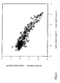
- Fig. 1 shows a relationship between the average value of the 2D video quality of the left eye video and the 2D video quality of the right eye video, and 3D video quality.
- Types of plotted points are classified into videos in which a difference of 2D video quality between the left eye video and the right eye video is large and videos in which the difference is small.
- Fig. 1 it can be understood that, as to videos in which the difference of 2D video quality between the left eye video and the right eye video is large, 3D video quality cannot be calculated accurately by the method using average values.
- the present invention is contrived in view of the above matter, and an object of the present invention is to provide a 3D video evaluation apparatus, a method and a program for calculating a 3D video quality accurately from 2D video qualities of the left eye video and the right eye video.
- the present invention is a video quality evaluation apparatus for evaluating a video quality that a user experiences for a service in which a 3D video is used, the video quality evaluation apparatus including:
- a 3D video quality can be calculated with high accuracy by using a model equation defined based on experiment results on influences that are exerted, on the 3D video, by 2D video qualities of the left eye video and the right eye video of the 3D video, which leads to proper quality design for a service in which the 3D video is used, and to realization of quality monitoring in service providing, so that the present invention can contribute to improvement of service value in quality.
- a 2D video quality (left eye video quality) of a left eye video included in a 3D video and a 2D video quality (right eye video quality) of a right eye video are calculated by using an existing 2D video quality evaluation algorithm.
- a 3D video quality is calculated from the left eye video quality and the right eye video quality by using a relationship model, which is obtained by experiment, among the left eye video quality, the right eye video quality and the 3D video quality.
- the relationship among the left eye video quality, the right eye video quality and the 3D video quality is described below.
- Fig. 2 shows the relationship among the left eye video quality, the right eye video quality and the 3D video quality, in which only points where the left eye video quality is higher than the right eye video quality are plotted. Difference of types of plotted points indicates difference of the left eye video quality, and the lateral axis indicates the right eye video quality and the vertical axis indicates the 3D video quality. A line segment in the figure indicates a regression line of the right eye video quality and the 3D video quality for each type of the plotted points. In a case where the left eye video quality is the same, there is a relationship that, the lower the right eye video quality is, the lower the 3D video quality is. But, the degree of the relationship is gradual, and, it can be understood that the left eye video quality of high quality has a larger effect on the 3D video quality than the right eye video quality (quality characteristic 1).
- Fig. 2 quality characteristics are derived by limiting to the condition where the left eye video is higher than the right eye video, and Fig. 2 shows that the 3D video quality has a high correlation with the left eye video quality, and in addition to that, Fig. 2 shows a relationship (quality characteristic 1) in which the 3D video quality gradually falls as the right eye video quality falls. At this time point, the case where quality of the left and right videos is reversed is not considered.
- quality characteristic 2 based on the characteristic that the 3D video quality does not change even though the quality of the right eye video and the left eye video is reversed (quality characteristic 2), it can be derived that there is a characteristic (quality characteristic 3) similar to the quality characteristic 1 also in a condition where the right eye video is higher than the left eye video.
- the 3D video quality can be calculated by classifying the left eye video and the right eye video into a video of high quality (base video) and a video of low quality (sub-video) and by performing correction based on the quality of the base video (base video quality) using the quality of the sub-video (sub-video quality).
- Fig. 3 indicates a relationship of a difference value between the 3D video quality and the base video quality and a difference value between the base video quality and the sub-video quality
- Fig. 3 indicates that the 3D video quality is influenced by the difference value between the base video quality and the sub-video quality.
- a correction is performed such that the difference value between the base video quality and the sub-video quality is subtracted from the base video quality (a correction such that the 3D video quality is decreased than the base video quality as the difference value becomes large). Details of the correction are described in equations (1)-(6).
- the present invention is an apparatus and a method for calculating a quality of a 3D video. More specifically, a left eye video quality of the 3D video and a right eye video quality of the 3D video are calculated separately, so that a 3D video quality is calculated from these qualities.
- the present invention is characterized in that the 3D video quality is calculated based on model equations defined based on experiment results on influences that are exerted by the left eye video quality and the right eye video quality on the quality of the 3D video.
- Fig. 4 shows a configuration of a video quality evaluation apparatus in an embodiment of the present invention.
- the video quality evaluation apparatus shown in the figure includes a 2D video data extraction unit 1, a 2D video quality derivation unit 2, and a 3D video quality derivation unit 3, and the video quality evaluation apparatus receives 3D video data as an input and outputs a 3D video quality.
- the 3D video data indicates a 3D video signal, a 3D video signal before information processing (coding process, transmission process and the like), or a packet including a 3D video signal or a combination of them.
- the 2D video data extraction unit 1 includes a left eye video data extraction unit 11 and a right eye video data extraction unit 12.
- the 2D video quality derivation unit 2 includes a left eye video quality calculation unit 21, a right eye video quality calculation unit 22 and a storage unit 23 for storing a 2D video quality evaluation algorithm (program), and each of the left eye video quality calculation unit 21 and the right eye video quality calculation unit 22 includes calculation process units 211 and 221 respectively.
- the 3D video quality derivation unit 3 includes a base video quality determination unit 31 and a 3D video quality calculation unit 32, and, as shown in Fig. 6 , the 3D video quality calculation unit 32 includes a calculation process unit 321 and a storage unit 322.
- the 3D video data supplied to the video quality evaluation apparatus is supplied to the left eye video data extraction unit 11 and the right eye video data extraction unit 12 in the 2D video data extraction unit 1.
- the 2D video data extraction unit 1 receives the 3D video data as an input.
- the left eye video data extraction unit 11 extracts left eye video data based on the input 3D video data and outputs the left eye video data as an input to the left eye video quality calculation unit 21, and the right eye video data extraction unit 12 extracts right eye video data based on the input 3D video data and outputs the right eye video data as an input to the right eye video quality calculation unit 22.
- the left eye video data extraction unit 11 extracts left eye video data included in the input 3D video data.
- the data structure of the 3D video data depends on a container format (AVI, MPEG and the like) of the input 3D video data.
- the 3D video data is not necessarily formed as a single piece of data, and there may be a case where data is separated beforehand between the left eye video and the right eye video.
- the format of the extracted left eye video data depends on the video quality evaluation algorithm used in the 2D video quality derivation unit 2, and the left eye video data may be a video signal of the left eye video, packet header information, packet bit stream information or the like.
- the left eye video data extraction unit 11 has a decoding function. But, as an embodiment, it is desirable that the apparatus is implemented assuming that the video signal is decoded before input.
- the right eye video data extraction unit 12 extracts right eye video data included in the input 3D video data.
- the data structure of the 3D video data depends on a container format (AVI, MPEG and the like) of the input 3D video data.
- the 3D video data is not necessarily formed as a single piece of data, and there may be a case where data is separated beforehand between the left eye video and the right eye video.
- the format of the extracted right eye video data depends on the video quality evaluation algorithm used in the 2D video quality derivation unit 2, and the right eye video data may be a video signal of the right eye video, packet header information, packet bit stream information or the like.
- the right eye video data extraction unit 12 has a decoding function. But, as an embodiment, it is desirable that the apparatus is implemented assuming that the video signal is decoded before input.
- the 2D video quality derivation unit 2 receives the left eye video data and the right eye video data as inputs, and the left eye video quality calculation unit 21 calculates left eye video quality based on the input left eye video data, and outputs the left eye video quality as an input to the base video quality determination unit 31.
- the right eye video quality calculation unit 22 calculates right eye video quality based on the input right eye video data, and outputs the right eye video quality as an input to the base video quality determination unit 31.
- the left eye video quality calculation unit 21 calculates a left eye video quality from the input left eye video data by using an existing 2D video quality evaluation algorithm described in the non-patent documents 1-4, for example.
- the video quality evaluation algorithm is stored in the storage unit 23 as a program, and is referred to by the calculation process unit 211 of the left eye video quality calculation unit 21.
- the format of the input 3D video data and units of evaluation (such as units of packets, frames, any time units (every 10 seconds, for example), whole video, and the like) depend on the video quality evaluation algorithm to be used.
- the right eye video quality calculation unit 22 calculates a right eye video quality from the input right eye video data by using an existing 2D video quality evaluation algorithm described in the non-patent documents 1-4, for example. As shown in Fig. 5 , the video quality evaluation algorithm is stored in the storage unit 23 as a program, and is referred to by the calculation process unit 221.
- the format of the input 3D video data and units of evaluation (such as units of packets, frames, any time units (every 10 seconds, for example), whole video, and the like) depend on the video quality evaluation algorithm to be used.
- the 3D video quality derivation unit 3 receives the left eye video quality and the right eye video quality as inputs, and the base video quality determination unit 31 calculates a base video quality and a sub-video quality based on the input left eye video quality and the input right eye video quality, and outputs the base video quality and the sub-video quality as an input to the 3D video quality calculation unit 32. Then, based on the input base video quality and the sub-video quality, the 3D video quality calculation unit 32 calculates a 3D video quality by using a model equation that is defined based on experimental results on effects that are exerted on the 3D video by the 2D video qualities of the left eye video and the right eye video of the 3D video.
- the base video quality determination unit 31 determines higher one of the input left eye video quality and the right eye video quality to be the base video quality, and determines lower one of them as the sub-video quality.
- the left eye video quality and the right eye video quality are the same, although either one of the left eye video quality and the right eye video quality may be referred to as the base video quality or the sub-video quality, the left eye video quality is determined to be the base video quality and the right eye video quality is determined to be the sub-video quality in the present embodiment.
- the determination process may be omitted, and the quality of one video may be uniquely set to be the base video quality, and another one may be set to be the sub-video quality.
- the 3D video quality calculation unit 32 calculates a 3D video quality VQ from the base video quality BQ and the sub-video quality SQ by using the following model equation (1).
- VQ v 1 ⁇ BQ - v 2 ⁇ BQ - SQ + v 3
- v 1 , v 2 and v 3 are coefficients, and it is necessary to optimize the model equation (1) based on the least-square method and the like by using a 3D video quality, a base video quality and a sub-video quality that are obtained by subjective quality evaluation experiment and the like beforehand.
- This model equation (1) calculates the 3D video quality based on the base video quality, and the model equation (1) models a relationship in which the 3D video quality gradually falls as the difference value between the base video quality and the sub-video quality becomes large.
- VQ v 4 ⁇ BQ ⁇ exp BQ - SQ / v 5
- VQ v 6 ⁇ BQ ⁇ exp SQ / BQ / v 7
- VQ v 8 ⁇ BQ - v 9 ⁇ SQ / BQ + v 10
- N 1 and N 2 are any positive numbers
- v 12 [j] and v 15 [j] are arrays having N 1 , N 2 elements respectively.
- model equations (2)-(6) calculate the 3D video quality based on the base video quality, and the model equations model a relationship in which the 3D video quality gradually falls as the difference value between the base video quality and the sub-video quality becomes large or as a ratio between the base video quality and the sub-video quality becomes small. Also, the model equations (5) and (6) consider a relationship in which a difference value between the 3D video quality and the base video quality becomes large nonlinearly toward a minus direction as the difference value between the base video quality and the sub-video quality becomes small or a ratio between the base video quality and the sub-video quality becomes small.
- the model equations (5) and (6) can estimate the 3D video quality with higher accuracy than the model equations (1)-(4).
- the model equations and the model coefficients are stored in the storage unit 322 as shown in Fig. 6 as a program and data to be used by the program, and are referred to by the calculation process unit 321.
- the left eye video data extraction unit 11 extracts left eye video data (video signal, packet header information, packet stream information of the left eye) from the input 3D video data and supplies the left eye video data to the left eye video quality calculation unit 21 (step 1).
- the right eye video data extraction unit 12 extracts right eye video data (video signal, packet header information, packet stream information of the right eye) from the input 3D video data and supplies the right eye video data to the right eye video quality calculation unit 22 (step 2).
- the left eye video quality calculation unit 21 calculates the left eye video quality from the input left eye video data by using a 2D video evaluation algorithm, and supplies the left eye video quality to the base video quality determination unit 31 (step 3).
- the right eye video quality calculation unit 22 calculates the right eye video quality from the input right eye video data by using a 2D video evaluation algorithm, and supplies the right eye video quality to the base video quality determination unit 31 (step 4).
- the base video quality determination unit 31 determines higher one of the input left eye video quality and the right eye video quality to be the base video quality, and determines lower one of them as the sub-video quality, and supplies them to the 3D video quality calculation unit 32 (step 5).
- the 3D video quality calculation unit 32 calculates the 3D video quality from the input base video quality and the sub-video quality by using a predetermined model equation (step 6).
- the video quality evaluation apparatus shown in Fig. 4 can be realized by causing one or a plurality of computers to execute a program describing processing content described in the present embodiment, for example. More specifically, functions of each unit of the video quality evaluation apparatus can be realized by executing a program corresponding to processes performed by each unit, by using hardware resources such as a CPU, a memory and a hard disk included in the computer that forms the video quality evaluation apparatus.
- a program for causing a computer to function as a video quality evaluation apparatus for evaluating a video quality that a user experiences for a service in which a 3D video is used, wherein the program causes the computer to function as: the 2D video quality derivation unit 2 configured to derive, from input 3D video data that is 3D video data which is input, a left eye video quality that is a quality of a left eye video that is included in the 3D video data and a right eye video quality that is a quality of a right eye video that is included in the 3D video data; and the 3D video quality derivation unit 3 configured to derive a 3D video quality from the left eye video quality and the right eye video quality.
- the 2D video quality derivation unit 2 configured to derive, from input 3D video data that is 3D video data which is input, a left eye video quality that is a quality of a left eye video that is included in the 3D video data and a right eye video quality that is a quality of a right eye video that is included
- a program may be provided for causing a computer to function as the 3D video quality derivation unit 3 configured to derive a 3D video quality from the left eye video quality and the right eye video quality.
- RAM Random Access Memory
- flash memory ROM (Read Only Memory)
- EPROM Erasable Programmable ROM
- EEPROM Electrically Erasable and Programmable ROM
- register hard disk, SD card, removable disk, CD-ROM and the like, for example.
Landscapes
- Engineering & Computer Science (AREA)
- Multimedia (AREA)
- Signal Processing (AREA)
- Health & Medical Sciences (AREA)
- Biomedical Technology (AREA)
- General Health & Medical Sciences (AREA)
- Testing, Inspecting, Measuring Of Stereoscopic Televisions And Televisions (AREA)
- Image Analysis (AREA)
Abstract
Description
- The present invention relates to a video quality evaluation apparatus, a method and a program. More particularly, the present invention relates to a video quality evaluation apparatus, a method and a program for quantifying stereoscopic (3D) video quality that a user experiences with respect to a service that uses 3D videos.
- Owing to development of Blue-
ray 3D and HDMI 1.4 standard, and standardization of H. 264/MVC and the like, an environment where 3D content can be viewed even in a standard home has been prepared. With that, also in video distribution services and package media, 3D video content is started to be provided in addition to 2D video content. - In the video distribution services and the package media, information amount compression of video content using video coding is performed in order to improve use efficiency of the network and the storage and to reduce service cost. By performing the information amount compression using video coding, deterioration such as mosaic-like distortion (block noise), blurring, bleeding, jerky feeling and the like occurs in the 2D video and the 3D video so that quality that the user experiences (QoE (Quality of Experience) deteriorates.
- Also, in a video distribution service via a network, when defect or corruption occurs in a part of data of the 2D video and the 3D video due to congestion of the network and the like, deterioration occurs in the 2D video and the 3D video, so that QoE deteriorates.
- For providing the service with good quality, and for detecting quality deterioration quickly, it is important to provide quality design in advance of service providing and to provide quality management while providing the service. For this purpose, an easy and efficient video quality evaluation technique is necessary for properly quantifying quality that the user experiences.
- In the past, a technique has been proposed for quantifying quality of 2D video based on pixel information of the 2D video or header information of packets including the 2D video (refer to non-patent documents 1-4, for example).
-
- [Non-patent document 1] ITU-T Recommendation J. 144
- [Non-patent document 2] ITU-T Recommendation J. 247
- [Non-patent document 3] Taichi Kawano, Keishiro Watanabe, and Jun Okamoto, "Study on no-reference type hybrid video quality assessment model," IEICE Tech. Rep., CQ2010-66, Nov. 2010.
- [Non-patent document 4] K. Yamagishi and T. Hayashi, "Parametric Packet-Layer Model for Monitoring Video Quality of IPTV Services," IEEE ICC 2008, CQ04-3, May 2008.
- [Non-patent document 5] Yuukou Horita, Yoshinao Kawai, Yohko Minami, Tadakuni Murai, Yoshio Nakashima,"Quality Evaluation Model of Coded Stereoscopic Color Image," IPSJ SIG Technical Reports, 2000(24), 31-36, Mar. 2000
- However, since the techniques described in the non-patent documents 1-4 are video quality evaluation techniques for 2D video, the techniques cannot directly support quality evaluation of 3D video. As a method for supporting quality evaluation of the 3D video, an approach can be considered in which a left eye video and a right eye video included in the 3D video data are regarded as two 2D videos, and quality of each 2D video is calculated by using a 2D video quality evaluation algorithm (techniques described in the non-patent documents 1-4, for example) so as to calculate an average value of the qualities of the two 2D videos as a quality of the 3D video.
Fig. 1 shows a relationship between the average value of the 2D video quality of the left eye video and the 2D video quality of the right eye video, and 3D video quality. Types of plotted points are classified into videos in which a difference of 2D video quality between the left eye video and the right eye video is large and videos in which the difference is small. As shown inFig. 1 , it can be understood that, as to videos in which the difference of 2D video quality between the left eye video and the right eye video is large, 3D video quality cannot be calculated accurately by the method using average values. - The present invention is contrived in view of the above matter, and an object of the present invention is to provide a 3D video evaluation apparatus, a method and a program for calculating a 3D video quality accurately from 2D video qualities of the left eye video and the right eye video.
- For solving the above-mentioned problem, the present invention is a video quality evaluation apparatus for evaluating a video quality that a user experiences for a service in which a 3D video is used, the video quality evaluation apparatus including:
- a 2D video quality derivation unit configured to derive, from
input 3D video data, a left eye video quality that is a quality of a left eye video that is included in the 3D video data and a right eye video quality that is a quality of a right eye video that is included in the 3D video data; and - a 3D video quality derivation unit configured to derive a quality of the 3D video from the left eye video quality and the right eye video quality.
- According to the present invention, a 3D video quality can be calculated with high accuracy by using a model equation defined based on experiment results on influences that are exerted, on the 3D video, by 2D video qualities of the left eye video and the right eye video of the 3D video, which leads to proper quality design for a service in which the 3D video is used, and to realization of quality monitoring in service providing, so that the present invention can contribute to improvement of service value in quality.
-
-
Fig. 1 is a diagram showing a relationship between an average value of a left eye video quality and a right eye video quality, and a 3D video quality; -
Fig. 2 is a diagram showing a relationship among the left eye video quality, the right eye video quality and the 3D video quality; -
Fig. 3 is a diagram showing a relationship of a difference value between the 3D video quality and a base video quality and a difference value between the base video quality and a sub-video quality; -
Fig. 4 is a block diagram of a video quality evaluation apparatus in an embodiment of the present invention; -
Fig. 5 is a block diagram of a 2D video quality derivation unit in an embodiment of the present invention; -
Fig. 6 is a block diagram of a 3D-video quality derivation unit in an embodiment of the present invention; and -
Fig. 7 is a flowchart of video quality evaluation in an embodiment of the present invention. - In the following, an embodiment of the present invention is described with reference to figures.
- In the embodiment of the present invention, first, a 2D video quality (left eye video quality) of a left eye video included in a 3D video and a 2D video quality (right eye video quality) of a right eye video are calculated by using an existing 2D video quality evaluation algorithm. Then, a 3D video quality is calculated from the left eye video quality and the right eye video quality by using a relationship model, which is obtained by experiment, among the left eye video quality, the right eye video quality and the 3D video quality.
- The relationship among the left eye video quality, the right eye video quality and the 3D video quality is described below.
- First, a relationship is described when the left eye video quality is higher than the right eye video quality.
Fig. 2 shows the relationship among the left eye video quality, the right eye video quality and the 3D video quality, in which only points where the left eye video quality is higher than the right eye video quality are plotted. Difference of types of plotted points indicates difference of the left eye video quality, and the lateral axis indicates the right eye video quality and the vertical axis indicates the 3D video quality. A line segment in the figure indicates a regression line of the right eye video quality and the 3D video quality for each type of the plotted points. In a case where the left eye video quality is the same, there is a relationship that, the lower the right eye video quality is, the lower the 3D video quality is. But, the degree of the relationship is gradual, and, it can be understood that the left eye video quality of high quality has a larger effect on the 3D video quality than the right eye video quality (quality characteristic 1). - Next, a relationship when the right eye video quality is higher than the left eye video quality is described. According to the non-patent document 5: Yuukou Horita, Yoshinao Kawai, Yohko Minami, Tadakuni Murai, Yoshio Nakashima,"Quality Evaluation Model of Coded Stereoscopic Color Image," IPSJ SIG Technical Reports, 2000(24), 31-36, Mar. 2000, even though the left eye video quality and the right eye video quality are reversed, how the quality exerts influences on the 3D video quality does not change, and it can be said that, when the right eye video quality is higher than the left eye video quality, the right eye video quality has a larger effect on the 3D video quality than the left eye video quality (quality characteristic 2).
- In
Fig. 2 , quality characteristics are derived by limiting to the condition where the left eye video is higher than the right eye video, andFig. 2 shows that the 3D video quality has a high correlation with the left eye video quality, and in addition to that,Fig. 2 shows a relationship (quality characteristic 1) in which the 3D video quality gradually falls as the right eye video quality falls. At this time point, the case where quality of the left and right videos is reversed is not considered. Next, based on the characteristic that the 3D video quality does not change even though the quality of the right eye video and the left eye video is reversed (quality characteristic 2), it can be derived that there is a characteristic (quality characteristic 3) similar to thequality characteristic 1 also in a condition where the right eye video is higher than the left eye video. Based on thequality characteristic 1 and thequality characteristic 3, it can be understood that there is a relationship that the 3D video quality is largely influenced by a video of higher quality in the left eye video and the right eye video, and that the 3D video quality is slightly influenced by a video of lower quality. Therefore, the 3D video quality can be calculated by classifying the left eye video and the right eye video into a video of high quality (base video) and a video of low quality (sub-video) and by performing correction based on the quality of the base video (base video quality) using the quality of the sub-video (sub-video quality). - More specifically,
Quality characteristics 1: "3D video quality = A(left eye video quality, right eye video quality) if left eye video quality ≥ right eye video quality", wherein A(M, N) indicates a function for calculating a 3D video quality by performing correction using a quality value N based on a quality value M, and
Quality characteristics 2: "3D video quality = B(left eye video quality, right eye video quality) = B(right eye video quality, left eye video quality)" are obtained, wherein B(M,N) indicates a function for calculating a 3D video quality from the quality value M and the quality value N, and A(M, N) is a form of B(M, N). - From the
quality characteristics quality characteristics -
Fig. 3 indicates a relationship of a difference value between the 3D video quality and the base video quality and a difference value between the base video quality and the sub-video quality, andFig. 3 indicates that the 3D video quality is influenced by the difference value between the base video quality and the sub-video quality. For deriving the 3D video quality, a correction is performed such that the difference value between the base video quality and the sub-video quality is subtracted from the base video quality (a correction such that the 3D video quality is decreased than the base video quality as the difference value becomes large). Details of the correction are described in equations (1)-(6). Also, as shown in the figure, since there is a non-linear relationship in the difference value between the 3D video quality and the base video quality and the difference value between the base video quality and the sub-video quality, it becomes possible to improve estimation accuracy of the 3D video quality by introducing model equations for which nonlinearity is considered. Details of the correction is described later in equations (5) and (6). - The present invention is an apparatus and a method for calculating a quality of a 3D video. More specifically, a left eye video quality of the 3D video and a right eye video quality of the 3D video are calculated separately, so that a 3D video quality is calculated from these qualities.
- The present invention is characterized in that the 3D video quality is calculated based on model equations defined based on experiment results on influences that are exerted by the left eye video quality and the right eye video quality on the quality of the 3D video.
-
Fig. 4 shows a configuration of a video quality evaluation apparatus in an embodiment of the present invention. - The video quality evaluation apparatus shown in the figure includes a 2D video
data extraction unit 1, a 2D videoquality derivation unit 2, and a 3D videoquality derivation unit 3, and the video quality evaluation apparatus receives 3D video data as an input and outputs a 3D video quality. In this embodiment, the 3D video data indicates a 3D video signal, a 3D video signal before information processing (coding process, transmission process and the like), or a packet including a 3D video signal or a combination of them. - The 2D video
data extraction unit 1 includes a left eye videodata extraction unit 11 and a right eye videodata extraction unit 12. - As shown in
Fig. 5 , the 2D videoquality derivation unit 2 includes a left eye videoquality calculation unit 21, a right eye videoquality calculation unit 22 and astorage unit 23 for storing a 2D video quality evaluation algorithm (program), and each of the left eye videoquality calculation unit 21 and the right eye videoquality calculation unit 22 includescalculation process units - The 3D video
quality derivation unit 3 includes a base videoquality determination unit 31 and a 3D videoquality calculation unit 32, and, as shown inFig. 6 , the 3D videoquality calculation unit 32 includes acalculation process unit 321 and astorage unit 322. - The 3D video data supplied to the video quality evaluation apparatus is supplied to the left eye video
data extraction unit 11 and the right eye videodata extraction unit 12 in the 2D videodata extraction unit 1. - The 2D video
data extraction unit 1 receives the 3D video data as an input. The left eye videodata extraction unit 11 extracts left eye video data based on theinput 3D video data and outputs the left eye video data as an input to the left eye videoquality calculation unit 21, and the right eye videodata extraction unit 12 extracts right eye video data based on theinput 3D video data and outputs the right eye video data as an input to the right eye videoquality calculation unit 22. - The left eye video
data extraction unit 11 extracts left eye video data included in theinput 3D video data. The data structure of the 3D video data depends on a container format (AVI, MPEG and the like) of theinput 3D video data. The 3D video data is not necessarily formed as a single piece of data, and there may be a case where data is separated beforehand between the left eye video and the right eye video. Also, the format of the extracted left eye video data depends on the video quality evaluation algorithm used in the 2D videoquality derivation unit 2, and the left eye video data may be a video signal of the left eye video, packet header information, packet bit stream information or the like. In a case where the video signal included in theinput 3D video data is encoded and the video signal is used as the left eye video data, it is necessary that the left eye videodata extraction unit 11 has a decoding function. But, as an embodiment, it is desirable that the apparatus is implemented assuming that the video signal is decoded before input. - The right eye video
data extraction unit 12 extracts right eye video data included in theinput 3D video data. The data structure of the 3D video data depends on a container format (AVI, MPEG and the like) of theinput 3D video data. The 3D video data is not necessarily formed as a single piece of data, and there may be a case where data is separated beforehand between the left eye video and the right eye video. Also, the format of the extracted right eye video data depends on the video quality evaluation algorithm used in the 2D videoquality derivation unit 2, and the right eye video data may be a video signal of the right eye video, packet header information, packet bit stream information or the like. In a case where the video signal included in theinput 3D video data is encoded and the video signal is used as the right eye video data, it is necessary that the right eye videodata extraction unit 12 has a decoding function. But, as an embodiment, it is desirable that the apparatus is implemented assuming that the video signal is decoded before input. - The 2D video
quality derivation unit 2 receives the left eye video data and the right eye video data as inputs, and the left eye videoquality calculation unit 21 calculates left eye video quality based on the input left eye video data, and outputs the left eye video quality as an input to the base videoquality determination unit 31. The right eye videoquality calculation unit 22 calculates right eye video quality based on the input right eye video data, and outputs the right eye video quality as an input to the base videoquality determination unit 31. - The left eye video
quality calculation unit 21 calculates a left eye video quality from the input left eye video data by using an existing 2D video quality evaluation algorithm described in the non-patent documents 1-4, for example. As shown inFig. 5 , the video quality evaluation algorithm is stored in thestorage unit 23 as a program, and is referred to by thecalculation process unit 211 of the left eye videoquality calculation unit 21. The format of theinput 3D video data and units of evaluation (such as units of packets, frames, any time units (every 10 seconds, for example), whole video, and the like) depend on the video quality evaluation algorithm to be used. - The right eye video
quality calculation unit 22 calculates a right eye video quality from the input right eye video data by using an existing 2D video quality evaluation algorithm described in the non-patent documents 1-4, for example. As shown inFig. 5 , the video quality evaluation algorithm is stored in thestorage unit 23 as a program, and is referred to by thecalculation process unit 221. The format of theinput 3D video data and units of evaluation (such as units of packets, frames, any time units (every 10 seconds, for example), whole video, and the like) depend on the video quality evaluation algorithm to be used. - The 3D video
quality derivation unit 3 receives the left eye video quality and the right eye video quality as inputs, and the base videoquality determination unit 31 calculates a base video quality and a sub-video quality based on the input left eye video quality and the input right eye video quality, and outputs the base video quality and the sub-video quality as an input to the 3D videoquality calculation unit 32. Then, based on the input base video quality and the sub-video quality, the 3D videoquality calculation unit 32 calculates a 3D video quality by using a model equation that is defined based on experimental results on effects that are exerted on the 3D video by the 2D video qualities of the left eye video and the right eye video of the 3D video. - The base video
quality determination unit 31 determines higher one of the input left eye video quality and the right eye video quality to be the base video quality, and determines lower one of them as the sub-video quality. When the values of the left eye video quality and the right eye video quality are the same, although either one of the left eye video quality and the right eye video quality may be referred to as the base video quality or the sub-video quality, the left eye video quality is determined to be the base video quality and the right eye video quality is determined to be the sub-video quality in the present embodiment. Also, depending on 3D video services, it can be considered that there is a case in which the left eye video quality or the right eye video quality is assumed to be always higher than the other one. In such a case, the determination process may be omitted, and the quality of one video may be uniquely set to be the base video quality, and another one may be set to be the sub-video quality. - The 3D video
quality calculation unit 32 calculates a 3D video quality VQ from the base video quality BQ and the sub-video quality SQ by using the following model equation (1).
In the equation, v1, v2 and v3 are coefficients, and it is necessary to optimize the model equation (1) based on the least-square method and the like by using a 3D video quality, a base video quality and a sub-video quality that are obtained by subjective quality evaluation experiment and the like beforehand. This model equation (1) calculates the 3D video quality based on the base video quality, and the model equation (1) models a relationship in which the 3D video quality gradually falls as the difference value between the base video quality and the sub-video quality becomes large. - In addition, any one of the following model equations may be used instead of (1).


In the equations, N1 and N2 are any positive numbers, v12[j] and v15[j] are arrays having N1, N2 elements respectively. As to the degree of the equation indicated by the value of N1 and N2, it is confirmed by experiments that apositive number 2 provides high estimation accuracy as expected. Each of v4, v5, v6, v7, v8, v9, v10, v11, v13, v14, v16, each element of v12 [j] and each element of v5[j] is a coefficient, and it is necessary to optimize the model equations based on the least-square method and the like by using a 3D video quality, a base video quality and a sub-video quality that are obtained by subjective quality evaluation experiment and the like beforehand. These model equations (2)-(6) calculate the 3D video quality based on the base video quality, and the model equations model a relationship in which the 3D video quality gradually falls as the difference value between the base video quality and the sub-video quality becomes large or as a ratio between the base video quality and the sub-video quality becomes small. Also, the model equations (5) and (6) consider a relationship in which a difference value between the 3D video quality and the base video quality becomes large nonlinearly toward a minus direction as the difference value between the base video quality and the sub-video quality becomes small or a ratio between the base video quality and the sub-video quality becomes small. The model equations (5) and (6) can estimate the 3D video quality with higher accuracy than the model equations (1)-(4). The model equations and the model coefficients are stored in thestorage unit 322 as shown inFig. 6 as a program and data to be used by the program, and are referred to by thecalculation process unit 321. - Next, a process flow of the present embodiment is described with reference to a flowchart of
Fig. 7 . - The left eye video
data extraction unit 11 extracts left eye video data (video signal, packet header information, packet stream information of the left eye) from theinput 3D video data and supplies the left eye video data to the left eye video quality calculation unit 21 (step 1). - The right eye video
data extraction unit 12 extracts right eye video data (video signal, packet header information, packet stream information of the right eye) from theinput 3D video data and supplies the right eye video data to the right eye video quality calculation unit 22 (step 2). - The left eye video
quality calculation unit 21 calculates the left eye video quality from the input left eye video data by using a 2D video evaluation algorithm, and supplies the left eye video quality to the base video quality determination unit 31 (step 3). - Next, the right eye video
quality calculation unit 22 calculates the right eye video quality from the input right eye video data by using a 2D video evaluation algorithm, and supplies the right eye video quality to the base video quality determination unit 31 (step 4). - Then, the base video
quality determination unit 31 determines higher one of the input left eye video quality and the right eye video quality to be the base video quality, and determines lower one of them as the sub-video quality, and supplies them to the 3D video quality calculation unit 32 (step 5). - Finally, the 3D video
quality calculation unit 32 calculates the 3D video quality from the input base video quality and the sub-video quality by using a predetermined model equation (step 6). - It is possible to construct each operation of the constituent elements of the video quality evaluation apparatus shown in
Fig. 4 as a program, and to install and run the program in a computer used as a video processing apparatus, or to circulate the program via a network. - That is, the video quality evaluation apparatus shown in
Fig. 4 can be realized by causing one or a plurality of computers to execute a program describing processing content described in the present embodiment, for example. More specifically, functions of each unit of the video quality evaluation apparatus can be realized by executing a program corresponding to processes performed by each unit, by using hardware resources such as a CPU, a memory and a hard disk included in the computer that forms the video quality evaluation apparatus. - That is, as an embodiment of the present invention, a program is provided for causing a computer to function as a video quality evaluation apparatus for evaluating a video quality that a user experiences for a service in which a 3D video is used, wherein the program causes the computer to function as: the 2D video
quality derivation unit 2 configured to derive, frominput 3D video data that is 3D video data which is input, a left eye video quality that is a quality of a left eye video that is included in the 3D video data and a right eye video quality that is a quality of a right eye video that is included in the 3D video data; and the 3D videoquality derivation unit 3 configured to derive a 3D video quality from the left eye video quality and the right eye video quality. Also, in a case where a 2D videoquality derivation unit 2 is realized by using an existing technique, as an embodiment of the present invention, a program, may be provided for causing a computer to function as the 3D videoquality derivation unit 3 configured to derive a 3D video quality from the left eye video quality and the right eye video quality. - It is possible to preserve and distribute the program by recording the program in a computer readable recording medium. Also, it is possible to provide the program via a network such as the Internet and an email. As the recording medium, there are RAM (Random Access Memory), flash memory, ROM (Read Only Memory), EPROM (Erasable Programmable ROM), EEPROM (Electronically Erasable and Programmable ROM), register, hard disk, SD card, removable disk, CD-ROM and the like, for example.
- The present invention is not limited to the specifically disclosed embodiments, and variations and modifications may be made without departing from the scope of the claims.
- The present international application claims priority based on Japanese patent application No.
2011-265991 filed on December 5, 2011 2012-147276 filed on June 29, 2012 2011-265991 2012-147276 -
- 1
- 2D video data extraction unit
- 2
- 2D video quality derivation unit
- 3
- 3D video quality derivation unit
- 11
- left eye video data extraction unit
- 12
- right eye video data extraction unit
- 21
- left eye video quality calculation unit
- 22
- right eye video quality calculation unit
- 23
- storage unit
- 31
- base video quality determination unit
- 32
- 3D video quality calculation unit
- 211, 221
- calculation process unit
- 321
- calculation process unit
- 322
- storage unit
Claims (8)
- A video quality evaluation apparatus for evaluating a video quality that a user experiences for a service in which a 3D video is used, the video quality evaluation apparatus comprising:a 2D video quality derivation unit configured to derive, from input 3D video data, a left eye video quality that is a quality of a left eye video that is included in the 3D video data and a right eye video quality that is a quality of a right eye video that is included in the 3D video data; anda 3D video quality derivation unit configured to derive a quality of the 3D video from the left eye video quality and the right eye video quality.
- The video quality evaluation apparatus as claimed in claim 1, the 2D video quality derivation unit including:a left eye video quality calculation unit configured to calculate the left eye video quality from left eye video data included in the input 3D video data by using a 2D video quality evaluation algorithm; anda right eye video quality calculation unit configured to calculate the right eye video quality from right eye video data included in the input 3D image data by using a 2D video quality evaluation algorithm.
- The video quality evaluation apparatus as claimed in claim 1 or 2, the 3D video quality derivation unit including:a base video quality determination unit configured to determine higher one of the left eye video quality and the right eye video quality to be a base video quality, and to determine lower one of them to be a sub-video quality.
- The video quality evaluation apparatus as claimed in any one of claims 1-3, the 3D video quality derivation unit including:a 3D video calculation unit configured to set a model equation representing a relationship among the base video quality, the sub-video quality and the 3D video quality, and to calculate a value of the 3D video quality from the base video quality and the sub-video quality based on the model equation.
- A video quality evaluation method in an apparatus for evaluating a video quality that a user experiences for a service in which a 3D video is used, the video quality evaluation method comprising:a 2D video quality derivation step in which a 2D video quality derivation unit derives, from input 3D video data, a left eye video quality that is a quality of a left eye video that is included in the 3D video data and a right eye video quality that is a quality of a right eye video that is included in the 3D video data; anda 3D video quality derivation step in which a 3D video quality derivation unit derives a quality of the 3D video from the left eye video quality and the right eye video quality.
- The video quality evaluation method as claimed in claim 5, the 2D video quality derivation step including:a left eye video quality calculation step of calculating the left eye video quality from left eye video data included in the input 3D video data by using a 2D video quality evaluation algorithm; anda right eye video quality calculation step of calculating the right eye video quality from right eye video data included in the input 3D video data by using a 2D video quality evaluation algorithm.
- The video quality evaluation method as claimed in claim 5, the 3D video quality derivation step including:a base video quality determination step of determining higher one of the left eye video quality and the right eye video quality to be a base video quality, and to determine lower one of them to be a sub-video quality; anda 3D video calculation step of setting a model equation representing a relationship among the base video quality, the sub-video quality and the 3D video quality, and calculating a value of the 3D video quality from the base video quality and the sub-video quality based on the model equation.
- A video quality evaluation program for causing a computer to function as each unit of the video quality evaluation apparatus as claimed in any one of claims 1-4.
Applications Claiming Priority (3)
| Application Number | Priority Date | Filing Date | Title |
|---|---|---|---|
| JP2011265991 | 2011-12-05 | ||
| JP2012147276 | 2012-06-29 | ||
| PCT/JP2012/081573 WO2013084965A1 (en) | 2011-12-05 | 2012-12-05 | Video quality evaluation device, method and program |
Publications (3)
| Publication Number | Publication Date |
|---|---|
| EP2790406A1 true EP2790406A1 (en) | 2014-10-15 |
| EP2790406A4 EP2790406A4 (en) | 2015-07-22 |
| EP2790406B1 EP2790406B1 (en) | 2017-09-27 |
Family
ID=48574323
Family Applications (1)
| Application Number | Title | Priority Date | Filing Date |
|---|---|---|---|
| EP12854733.8A Active EP2790406B1 (en) | 2011-12-05 | 2012-12-05 | Video quality evaluation device, method and program |
Country Status (5)
| Country | Link |
|---|---|
| US (1) | US9924149B2 (en) |
| EP (1) | EP2790406B1 (en) |
| JP (1) | JP5938049B2 (en) |
| CN (1) | CN103959772B (en) |
| WO (1) | WO2013084965A1 (en) |
Cited By (1)
| Publication number | Priority date | Publication date | Assignee | Title |
|---|---|---|---|---|
| CN106888374A (en) * | 2015-12-16 | 2017-06-23 | 联芯科技有限公司 | A kind of 3 d video encoding method, device and video processing equipment |
Families Citing this family (3)
| Publication number | Priority date | Publication date | Assignee | Title |
|---|---|---|---|---|
| CN103533343B (en) * | 2013-09-29 | 2015-05-20 | 宁波大学 | Stereo image quality objective evaluation method based on digital watermarking |
| CN108648207B (en) * | 2018-05-10 | 2021-07-09 | 天津大学 | Stereoscopic image quality evaluation method based on segmented stack autoencoder |
| WO2022251284A1 (en) | 2021-05-26 | 2022-12-01 | Magna International Inc. | Skateboard chassis assembly for an electric vehicle |
Family Cites Families (9)
| Publication number | Priority date | Publication date | Assignee | Title |
|---|---|---|---|---|
| JP3969688B2 (en) | 1999-03-24 | 2007-09-05 | 株式会社リコー | Binocular stereoscopic image evaluation apparatus, binocular stereoscopic image evaluation method, and recording medium |
| JP2000276595A (en) | 1999-03-25 | 2000-10-06 | Ricoh Co Ltd | Binocular stereoscopic image evaluation apparatus, binocular stereoscopic image evaluation method, and recording medium |
| JP2001292449A (en) | 2000-04-10 | 2001-10-19 | Nihon Visual Science Inc | Image processing unit, image processing method, and recording medium |
| DE102004007049A1 (en) | 2004-02-13 | 2005-09-01 | Robert Bosch Gmbh | Method for classifying an object with a stereo camera |
| US8594180B2 (en) * | 2007-02-21 | 2013-11-26 | Qualcomm Incorporated | 3D video encoding |
| JP5305094B2 (en) * | 2009-03-19 | 2013-10-02 | ソニー株式会社 | Video signal processing apparatus, stereoscopic video display apparatus, stereoscopic video transmission display system, and video signal processing method |
| CN101872479B (en) * | 2010-06-09 | 2012-05-09 | 宁波大学 | Three-dimensional image objective quality evaluation method |
| US8963998B2 (en) * | 2011-04-15 | 2015-02-24 | Tektronix, Inc. | Full reference system for predicting subjective quality of three-dimensional video |
| CN102209257B (en) * | 2011-06-17 | 2013-11-20 | 宁波大学 | Stereo image quality objective evaluation method |
-
2012
- 2012-12-05 EP EP12854733.8A patent/EP2790406B1/en active Active
- 2012-12-05 US US14/359,490 patent/US9924149B2/en active Active
- 2012-12-05 CN CN201280058954.7A patent/CN103959772B/en active Active
- 2012-12-05 WO PCT/JP2012/081573 patent/WO2013084965A1/en not_active Ceased
- 2012-12-05 JP JP2013548283A patent/JP5938049B2/en active Active
Cited By (2)
| Publication number | Priority date | Publication date | Assignee | Title |
|---|---|---|---|---|
| CN106888374A (en) * | 2015-12-16 | 2017-06-23 | 联芯科技有限公司 | A kind of 3 d video encoding method, device and video processing equipment |
| CN106888374B (en) * | 2015-12-16 | 2018-11-20 | 联芯科技有限公司 | A kind of 3 d video encoding method, apparatus and video processing equipment |
Also Published As
| Publication number | Publication date |
|---|---|
| EP2790406A4 (en) | 2015-07-22 |
| WO2013084965A1 (en) | 2013-06-13 |
| CN103959772A (en) | 2014-07-30 |
| CN103959772B (en) | 2016-10-12 |
| US9924149B2 (en) | 2018-03-20 |
| JP5938049B2 (en) | 2016-06-22 |
| JPWO2013084965A1 (en) | 2015-07-30 |
| US20140320598A1 (en) | 2014-10-30 |
| EP2790406B1 (en) | 2017-09-27 |
Similar Documents
| Publication | Publication Date | Title |
|---|---|---|
| EP2701397B1 (en) | Content-dependent video quality model for video streaming services | |
| WO2020194092A1 (en) | Unified end-to-end quality and latency measurement, optimization and management in multimedia communications | |
| EP2482558B1 (en) | Method, apparatus and system for evaluation of video transmission quality | |
| EP3125550A1 (en) | Method and apparatus for obtaining video quality parameter, and electronic device | |
| CN110546953A (en) | Complexity adaptive one-way transcoding and two-way transcoding | |
| EP2790406B1 (en) | Video quality evaluation device, method and program | |
| EP4111697B1 (en) | Real-time latency measurement of video streams | |
| EP3393125A1 (en) | Audio/visual quality estimation device, method for estimating audio/visual quality, and program | |
| JP7380832B2 (en) | Mathematical model derivation device, mathematical model derivation method and program | |
| EP3420698B1 (en) | Predicting multimedia session mos | |
| JP4787210B2 (en) | Video quality estimation method, apparatus, and program | |
| US9609361B2 (en) | Method for fast 3D video coding for HEVC | |
| EP2786584B1 (en) | Distortion/quality measurement | |
| EP3631752B1 (en) | Mutual noise estimation for videos | |
| EP2525586A1 (en) | Method and arrangement for supporting quality estimation of streamed video | |
| JP6228906B2 (en) | Video quality estimation apparatus, method and program | |
| Cheon et al. | Quality assessment of mobile videos | |
| Lee et al. | Hybrid no-reference video quality models for H. 264 with encrypted payload | |
| CN104488265B (en) | For the video quality model that the content of video streaming services is relevant | |
| JP6431449B2 (en) | Video matching apparatus, video matching method, and program | |
| Thakur et al. | A hybrid video quality metric for analyzing quality degradation due to frame drop | |
| López Velasco et al. | Blind quality algorithm to analyze streaming video contents in 5g networks | |
| Skarseth et al. | OPVQ and OpenVQ |
Legal Events
| Date | Code | Title | Description |
|---|---|---|---|
| PUAI | Public reference made under article 153(3) epc to a published international application that has entered the european phase |
Free format text: ORIGINAL CODE: 0009012 |
|
| 17P | Request for examination filed |
Effective date: 20140522 |
|
| AK | Designated contracting states |
Kind code of ref document: A1 Designated state(s): AL AT BE BG CH CY CZ DE DK EE ES FI FR GB GR HR HU IE IS IT LI LT LU LV MC MK MT NL NO PL PT RO RS SE SI SK SM TR |
|
| DAX | Request for extension of the european patent (deleted) | ||
| RA4 | Supplementary search report drawn up and despatched (corrected) |
Effective date: 20150622 |
|
| RIC1 | Information provided on ipc code assigned before grant |
Ipc: H04N 13/00 20060101ALI20150616BHEP Ipc: H04N 17/00 20060101AFI20150616BHEP |
|
| GRAP | Despatch of communication of intention to grant a patent |
Free format text: ORIGINAL CODE: EPIDOSNIGR1 |
|
| INTG | Intention to grant announced |
Effective date: 20170410 |
|
| GRAS | Grant fee paid |
Free format text: ORIGINAL CODE: EPIDOSNIGR3 |
|
| GRAA | (expected) grant |
Free format text: ORIGINAL CODE: 0009210 |
|
| AK | Designated contracting states |
Kind code of ref document: B1 Designated state(s): AL AT BE BG CH CY CZ DE DK EE ES FI FR GB GR HR HU IE IS IT LI LT LU LV MC MK MT NL NO PL PT RO RS SE SI SK SM TR |
|
| REG | Reference to a national code |
Ref country code: GB Ref legal event code: FG4D |
|
| REG | Reference to a national code |
Ref country code: CH Ref legal event code: EP |
|
| REG | Reference to a national code |
Ref country code: AT Ref legal event code: REF Ref document number: 933008 Country of ref document: AT Kind code of ref document: T Effective date: 20171015 |
|
| REG | Reference to a national code |
Ref country code: IE Ref legal event code: FG4D |
|
| REG | Reference to a national code |
Ref country code: DE Ref legal event code: R096 Ref document number: 602012037972 Country of ref document: DE |
|
| PG25 | Lapsed in a contracting state [announced via postgrant information from national office to epo] |
Ref country code: HR Free format text: LAPSE BECAUSE OF FAILURE TO SUBMIT A TRANSLATION OF THE DESCRIPTION OR TO PAY THE FEE WITHIN THE PRESCRIBED TIME-LIMIT Effective date: 20170927 Ref country code: NO Free format text: LAPSE BECAUSE OF FAILURE TO SUBMIT A TRANSLATION OF THE DESCRIPTION OR TO PAY THE FEE WITHIN THE PRESCRIBED TIME-LIMIT Effective date: 20171227 Ref country code: SE Free format text: LAPSE BECAUSE OF FAILURE TO SUBMIT A TRANSLATION OF THE DESCRIPTION OR TO PAY THE FEE WITHIN THE PRESCRIBED TIME-LIMIT Effective date: 20170927 Ref country code: FI Free format text: LAPSE BECAUSE OF FAILURE TO SUBMIT A TRANSLATION OF THE DESCRIPTION OR TO PAY THE FEE WITHIN THE PRESCRIBED TIME-LIMIT Effective date: 20170927 Ref country code: LT Free format text: LAPSE BECAUSE OF FAILURE TO SUBMIT A TRANSLATION OF THE DESCRIPTION OR TO PAY THE FEE WITHIN THE PRESCRIBED TIME-LIMIT Effective date: 20170927 |
|
| REG | Reference to a national code |
Ref country code: NL Ref legal event code: MP Effective date: 20170927 |
|
| REG | Reference to a national code |
Ref country code: LT Ref legal event code: MG4D |
|
| REG | Reference to a national code |
Ref country code: AT Ref legal event code: MK05 Ref document number: 933008 Country of ref document: AT Kind code of ref document: T Effective date: 20170927 |
|
| PG25 | Lapsed in a contracting state [announced via postgrant information from national office to epo] |
Ref country code: BG Free format text: LAPSE BECAUSE OF FAILURE TO SUBMIT A TRANSLATION OF THE DESCRIPTION OR TO PAY THE FEE WITHIN THE PRESCRIBED TIME-LIMIT Effective date: 20171227 Ref country code: LV Free format text: LAPSE BECAUSE OF FAILURE TO SUBMIT A TRANSLATION OF THE DESCRIPTION OR TO PAY THE FEE WITHIN THE PRESCRIBED TIME-LIMIT Effective date: 20170927 Ref country code: RS Free format text: LAPSE BECAUSE OF FAILURE TO SUBMIT A TRANSLATION OF THE DESCRIPTION OR TO PAY THE FEE WITHIN THE PRESCRIBED TIME-LIMIT Effective date: 20170927 Ref country code: GR Free format text: LAPSE BECAUSE OF FAILURE TO SUBMIT A TRANSLATION OF THE DESCRIPTION OR TO PAY THE FEE WITHIN THE PRESCRIBED TIME-LIMIT Effective date: 20171228 |
|
| PG25 | Lapsed in a contracting state [announced via postgrant information from national office to epo] |
Ref country code: NL Free format text: LAPSE BECAUSE OF FAILURE TO SUBMIT A TRANSLATION OF THE DESCRIPTION OR TO PAY THE FEE WITHIN THE PRESCRIBED TIME-LIMIT Effective date: 20170927 |
|
| PG25 | Lapsed in a contracting state [announced via postgrant information from national office to epo] |
Ref country code: RO Free format text: LAPSE BECAUSE OF FAILURE TO SUBMIT A TRANSLATION OF THE DESCRIPTION OR TO PAY THE FEE WITHIN THE PRESCRIBED TIME-LIMIT Effective date: 20170927 Ref country code: ES Free format text: LAPSE BECAUSE OF FAILURE TO SUBMIT A TRANSLATION OF THE DESCRIPTION OR TO PAY THE FEE WITHIN THE PRESCRIBED TIME-LIMIT Effective date: 20170927 Ref country code: CZ Free format text: LAPSE BECAUSE OF FAILURE TO SUBMIT A TRANSLATION OF THE DESCRIPTION OR TO PAY THE FEE WITHIN THE PRESCRIBED TIME-LIMIT Effective date: 20170927 |
|
| PG25 | Lapsed in a contracting state [announced via postgrant information from national office to epo] |
Ref country code: IT Free format text: LAPSE BECAUSE OF FAILURE TO SUBMIT A TRANSLATION OF THE DESCRIPTION OR TO PAY THE FEE WITHIN THE PRESCRIBED TIME-LIMIT Effective date: 20170927 Ref country code: SK Free format text: LAPSE BECAUSE OF FAILURE TO SUBMIT A TRANSLATION OF THE DESCRIPTION OR TO PAY THE FEE WITHIN THE PRESCRIBED TIME-LIMIT Effective date: 20170927 Ref country code: EE Free format text: LAPSE BECAUSE OF FAILURE TO SUBMIT A TRANSLATION OF THE DESCRIPTION OR TO PAY THE FEE WITHIN THE PRESCRIBED TIME-LIMIT Effective date: 20170927 Ref country code: SM Free format text: LAPSE BECAUSE OF FAILURE TO SUBMIT A TRANSLATION OF THE DESCRIPTION OR TO PAY THE FEE WITHIN THE PRESCRIBED TIME-LIMIT Effective date: 20170927 Ref country code: AT Free format text: LAPSE BECAUSE OF FAILURE TO SUBMIT A TRANSLATION OF THE DESCRIPTION OR TO PAY THE FEE WITHIN THE PRESCRIBED TIME-LIMIT Effective date: 20170927 Ref country code: IS Free format text: LAPSE BECAUSE OF FAILURE TO SUBMIT A TRANSLATION OF THE DESCRIPTION OR TO PAY THE FEE WITHIN THE PRESCRIBED TIME-LIMIT Effective date: 20180127 |
|
| REG | Reference to a national code |
Ref country code: DE Ref legal event code: R097 Ref document number: 602012037972 Country of ref document: DE |
|
| PG25 | Lapsed in a contracting state [announced via postgrant information from national office to epo] |
Ref country code: DK Free format text: LAPSE BECAUSE OF FAILURE TO SUBMIT A TRANSLATION OF THE DESCRIPTION OR TO PAY THE FEE WITHIN THE PRESCRIBED TIME-LIMIT Effective date: 20170927 |
|
| REG | Reference to a national code |
Ref country code: CH Ref legal event code: PL |
|
| PLBE | No opposition filed within time limit |
Free format text: ORIGINAL CODE: 0009261 |
|
| STAA | Information on the status of an ep patent application or granted ep patent |
Free format text: STATUS: NO OPPOSITION FILED WITHIN TIME LIMIT |
|
| GBPC | Gb: european patent ceased through non-payment of renewal fee |
Effective date: 20171227 |
|
| PG25 | Lapsed in a contracting state [announced via postgrant information from national office to epo] |
Ref country code: PL Free format text: LAPSE BECAUSE OF FAILURE TO SUBMIT A TRANSLATION OF THE DESCRIPTION OR TO PAY THE FEE WITHIN THE PRESCRIBED TIME-LIMIT Effective date: 20170927 |
|
| 26N | No opposition filed |
Effective date: 20180628 |
|
| REG | Reference to a national code |
Ref country code: IE Ref legal event code: MM4A |
|
| PG25 | Lapsed in a contracting state [announced via postgrant information from national office to epo] |
Ref country code: MT Free format text: LAPSE BECAUSE OF NON-PAYMENT OF DUE FEES Effective date: 20171205 Ref country code: LU Free format text: LAPSE BECAUSE OF NON-PAYMENT OF DUE FEES Effective date: 20171205 |
|
| REG | Reference to a national code |
Ref country code: FR Ref legal event code: ST Effective date: 20180831 |
|
| REG | Reference to a national code |
Ref country code: BE Ref legal event code: MM Effective date: 20171231 |
|
| PG25 | Lapsed in a contracting state [announced via postgrant information from national office to epo] |
Ref country code: IE Free format text: LAPSE BECAUSE OF NON-PAYMENT OF DUE FEES Effective date: 20171205 Ref country code: FR Free format text: LAPSE BECAUSE OF NON-PAYMENT OF DUE FEES Effective date: 20180102 |
|
| PG25 | Lapsed in a contracting state [announced via postgrant information from national office to epo] |
Ref country code: GB Free format text: LAPSE BECAUSE OF NON-PAYMENT OF DUE FEES Effective date: 20171227 Ref country code: CH Free format text: LAPSE BECAUSE OF NON-PAYMENT OF DUE FEES Effective date: 20171231 Ref country code: LI Free format text: LAPSE BECAUSE OF NON-PAYMENT OF DUE FEES Effective date: 20171231 Ref country code: SI Free format text: LAPSE BECAUSE OF FAILURE TO SUBMIT A TRANSLATION OF THE DESCRIPTION OR TO PAY THE FEE WITHIN THE PRESCRIBED TIME-LIMIT Effective date: 20170927 Ref country code: BE Free format text: LAPSE BECAUSE OF NON-PAYMENT OF DUE FEES Effective date: 20171231 |
|
| PG25 | Lapsed in a contracting state [announced via postgrant information from national office to epo] |
Ref country code: HU Free format text: LAPSE BECAUSE OF FAILURE TO SUBMIT A TRANSLATION OF THE DESCRIPTION OR TO PAY THE FEE WITHIN THE PRESCRIBED TIME-LIMIT; INVALID AB INITIO Effective date: 20121205 Ref country code: MC Free format text: LAPSE BECAUSE OF FAILURE TO SUBMIT A TRANSLATION OF THE DESCRIPTION OR TO PAY THE FEE WITHIN THE PRESCRIBED TIME-LIMIT Effective date: 20170927 |
|
| PG25 | Lapsed in a contracting state [announced via postgrant information from national office to epo] |
Ref country code: CY Free format text: LAPSE BECAUSE OF FAILURE TO SUBMIT A TRANSLATION OF THE DESCRIPTION OR TO PAY THE FEE WITHIN THE PRESCRIBED TIME-LIMIT Effective date: 20170927 |
|
| PG25 | Lapsed in a contracting state [announced via postgrant information from national office to epo] |
Ref country code: MK Free format text: LAPSE BECAUSE OF FAILURE TO SUBMIT A TRANSLATION OF THE DESCRIPTION OR TO PAY THE FEE WITHIN THE PRESCRIBED TIME-LIMIT Effective date: 20170927 |
|
| PG25 | Lapsed in a contracting state [announced via postgrant information from national office to epo] |
Ref country code: TR Free format text: LAPSE BECAUSE OF FAILURE TO SUBMIT A TRANSLATION OF THE DESCRIPTION OR TO PAY THE FEE WITHIN THE PRESCRIBED TIME-LIMIT Effective date: 20170927 |
|
| PG25 | Lapsed in a contracting state [announced via postgrant information from national office to epo] |
Ref country code: PT Free format text: LAPSE BECAUSE OF FAILURE TO SUBMIT A TRANSLATION OF THE DESCRIPTION OR TO PAY THE FEE WITHIN THE PRESCRIBED TIME-LIMIT Effective date: 20170927 |
|
| PG25 | Lapsed in a contracting state [announced via postgrant information from national office to epo] |
Ref country code: AL Free format text: LAPSE BECAUSE OF FAILURE TO SUBMIT A TRANSLATION OF THE DESCRIPTION OR TO PAY THE FEE WITHIN THE PRESCRIBED TIME-LIMIT Effective date: 20170927 |
|
| PGFP | Annual fee paid to national office [announced via postgrant information from national office to epo] |
Ref country code: DE Payment date: 20251211 Year of fee payment: 14 |
|
| REG | Reference to a national code |
Ref country code: DE Ref legal event code: R081 Ref document number: 602012037972 Country of ref document: DE Owner name: NTT, INC., JP Free format text: FORMER OWNER: NIPPON TELEGRAPH AND TELEPHONE CORPORATION, TOKYO, JP Ref country code: DE Ref legal event code: R082 Ref document number: 602012037972 Country of ref document: DE Representative=s name: DENNEMEYER & ASSOCIATES RECHTSANWALTSGESELLSCH, DE |